EP3486541B1 - Method of manufacturing an eight sided forged ferrule staking crimped fitting - Google Patents
Method of manufacturing an eight sided forged ferrule staking crimped fitting Download PDFInfo
- Publication number
- EP3486541B1 EP3486541B1 EP18206909.6A EP18206909A EP3486541B1 EP 3486541 B1 EP3486541 B1 EP 3486541B1 EP 18206909 A EP18206909 A EP 18206909A EP 3486541 B1 EP3486541 B1 EP 3486541B1
- Authority
- EP
- European Patent Office
- Prior art keywords
- stem
- ferrule
- hose
- crimp
- wrench surface
- Prior art date
- Legal status (The legal status is an assumption and is not a legal conclusion. Google has not performed a legal analysis and makes no representation as to the accuracy of the status listed.)
- Active
Links
Images

Classifications
-
- B—PERFORMING OPERATIONS; TRANSPORTING
- B21—MECHANICAL METAL-WORKING WITHOUT ESSENTIALLY REMOVING MATERIAL; PUNCHING METAL
- B21D—WORKING OR PROCESSING OF SHEET METAL OR METAL TUBES, RODS OR PROFILES WITHOUT ESSENTIALLY REMOVING MATERIAL; PUNCHING METAL
- B21D39/00—Application of procedures in order to connect objects or parts, e.g. coating with sheet metal otherwise than by plating; Tube expanders
- B21D39/04—Application of procedures in order to connect objects or parts, e.g. coating with sheet metal otherwise than by plating; Tube expanders of tubes with tubes; of tubes with rods
- B21D39/048—Application of procedures in order to connect objects or parts, e.g. coating with sheet metal otherwise than by plating; Tube expanders of tubes with tubes; of tubes with rods using presses for radially crimping tubular elements
-
- F—MECHANICAL ENGINEERING; LIGHTING; HEATING; WEAPONS; BLASTING
- F16—ENGINEERING ELEMENTS AND UNITS; GENERAL MEASURES FOR PRODUCING AND MAINTAINING EFFECTIVE FUNCTIONING OF MACHINES OR INSTALLATIONS; THERMAL INSULATION IN GENERAL
- F16L—PIPES; JOINTS OR FITTINGS FOR PIPES; SUPPORTS FOR PIPES, CABLES OR PROTECTIVE TUBING; MEANS FOR THERMAL INSULATION IN GENERAL
- F16L19/00—Joints in which sealing surfaces are pressed together by means of a member, e.g. a swivel nut, screwed on, or into, one of the joint parts
- F16L19/02—Pipe ends provided with collars or flanges, integral with the pipe or not, pressed together by a screwed member
- F16L19/025—Pipe ends provided with collars or flanges, integral with the pipe or not, pressed together by a screwed member the pipe ends having integral collars or flanges
-
- F—MECHANICAL ENGINEERING; LIGHTING; HEATING; WEAPONS; BLASTING
- F16—ENGINEERING ELEMENTS AND UNITS; GENERAL MEASURES FOR PRODUCING AND MAINTAINING EFFECTIVE FUNCTIONING OF MACHINES OR INSTALLATIONS; THERMAL INSULATION IN GENERAL
- F16L—PIPES; JOINTS OR FITTINGS FOR PIPES; SUPPORTS FOR PIPES, CABLES OR PROTECTIVE TUBING; MEANS FOR THERMAL INSULATION IN GENERAL
- F16L33/00—Arrangements for connecting hoses to rigid members; Rigid hose-connectors, i.e. single members engaging both hoses
- F16L33/20—Undivided rings, sleeves, or like members contracted on the hose or expanded inside the hose by means of tools; Arrangements using such members
- F16L33/207—Undivided rings, sleeves, or like members contracted on the hose or expanded inside the hose by means of tools; Arrangements using such members only a sleeve being contracted on the hose
- F16L33/2071—Undivided rings, sleeves, or like members contracted on the hose or expanded inside the hose by means of tools; Arrangements using such members only a sleeve being contracted on the hose the sleeve being a separate connecting member
- F16L33/2073—Undivided rings, sleeves, or like members contracted on the hose or expanded inside the hose by means of tools; Arrangements using such members only a sleeve being contracted on the hose the sleeve being a separate connecting member directly connected to the rigid member
- F16L33/2076—Undivided rings, sleeves, or like members contracted on the hose or expanded inside the hose by means of tools; Arrangements using such members only a sleeve being contracted on the hose the sleeve being a separate connecting member directly connected to the rigid member by plastic deformation
-
- F—MECHANICAL ENGINEERING; LIGHTING; HEATING; WEAPONS; BLASTING
- F16—ENGINEERING ELEMENTS AND UNITS; GENERAL MEASURES FOR PRODUCING AND MAINTAINING EFFECTIVE FUNCTIONING OF MACHINES OR INSTALLATIONS; THERMAL INSULATION IN GENERAL
- F16L—PIPES; JOINTS OR FITTINGS FOR PIPES; SUPPORTS FOR PIPES, CABLES OR PROTECTIVE TUBING; MEANS FOR THERMAL INSULATION IN GENERAL
- F16L33/00—Arrangements for connecting hoses to rigid members; Rigid hose-connectors, i.e. single members engaging both hoses
- F16L33/22—Arrangements for connecting hoses to rigid members; Rigid hose-connectors, i.e. single members engaging both hoses with means not mentioned in the preceding groups for gripping the hose between inner and outer parts
-
- F—MECHANICAL ENGINEERING; LIGHTING; HEATING; WEAPONS; BLASTING
- F16—ENGINEERING ELEMENTS AND UNITS; GENERAL MEASURES FOR PRODUCING AND MAINTAINING EFFECTIVE FUNCTIONING OF MACHINES OR INSTALLATIONS; THERMAL INSULATION IN GENERAL
- F16L—PIPES; JOINTS OR FITTINGS FOR PIPES; SUPPORTS FOR PIPES, CABLES OR PROTECTIVE TUBING; MEANS FOR THERMAL INSULATION IN GENERAL
- F16L33/00—Arrangements for connecting hoses to rigid members; Rigid hose-connectors, i.e. single members engaging both hoses
- F16L33/30—Arrangements for connecting hoses to rigid members; Rigid hose-connectors, i.e. single members engaging both hoses comprising parts inside the hoses only
Definitions
- the present disclosure relates generally to hydraulic hose fittings, and methods making such, and more particularly to an octagonal shape on an outer portion of a ferrule of a fitting.
- Hose fittings are used to connect a fluid line or hose to various types of industrial equipment and machinery via the equipment connection ports or manifolds.
- a hose fitting typically has two ends: one end generally defines the hose connection end and the other end generally defines the equipment connection end.
- a stem is provided having a first end, the equipment connection end, and a second end, the hose connection end, wherein the second end includes a shell placed over the stem.
- the first end of the stem may be threaded or may include a nut placed thereon for engaging the equipment.
- the external surface of the second end of the stem typically engages the internal surface of a hose, while the internal surface of the shell engages the external surface of the hose.
- a wrenching surface such as a hexagonal surface
- a wrench, or other suitable tool may be used to engage the wrenching surface while securing the equipment connection end of the fluid coupling to the equipment. This maintains stability of the hose connection end and prevents damage to the hose and/or its connection to the coupling by a resulting tendency to twist during the securing procedure.
- the hexagonal surface is generally provided at a different horizontal location of the fluid coupling than the horizontal location of a joined portion of the stem and the shell. Common methods of joining the coupling pieces include crimping, staking, swaging, etc.
- Some hydraulic hose fittings require two hexes on the fitting.
- One hexagonal is on a swivel nut and the second hexagonal is solid and formed the stem.
- one wrench rotates the swivel nut and a second wrench prevents the stem from rotating.
- the inner diameter of the swivel nut is smaller than the hexagonal size on the stem.
- the stationary hexagonal on the stem is created by machining hexagonal bar stock or forging the hexagonal into the stem.
- the connection end of the fitting is left as an open tube.
- a tube nut slides over the open end of the tube and a larger outer diameter part is brazed onto the end of the tube to retain the swivel nut.
- the stem is machined out of hexagonal bar stock or forged with a hexagonal on the stem.
- the shoulder that retains the swivel nut is machined solid onto the stem so no brazing is required.
- the swivel nut is then crimped over the shoulder on the stem so it is retained by the shoulder.
- hexagonal wrench flats have limited flats for engaging a wrench.
- Brazing two stem sections together requires an additional process step which increases cost and creates a potential leak at the brazed connection.
- Crimping the swivel nut onto the stem requires an additional process step which increases cost and the crimped nut has lower max torque values compared to tube nut designs.
- US 3,512,810 A relates to a hose fitting and a fitting of the type having a nipple for insertion within the end of a hose and a socket for squeezing the hose wall against the nipple.
- methods of making hose fittings include providing a stem having a fluid conduit, a first end, a second end with a raised shoulder, and a crimp region disposed between the first end and the second end.
- the crimp region includes knurls and/or raised grooves for mating with a ferrule.
- the stem may include barbs for sealingly engaging an inner diameter of a hose.
- a swivel tube nut is then placed over the stem, and the swivel tube nut is retained on the stem the by the raised shoulder.
- a ferrule is thereafter placed over the first end of the stem, and the ferrule comprises a partially or fully formed octagonal wrench surface, formed prior to. The ferrule is then crimped, at the octagonal wrench surface, onto the crimp region of the stem.
- the crimping is conducted using a crimp die tool.
- the crimp die tool may include at least two die pieces engaging the octagonal wrench surface of the ferrule, or at least four die pieces engaging the octagonal wrench surface of the ferrule, or even at least eight die pieces engaging the octagonal wrench surface of the ferrule.
- the hose fitting consists of the swivel tube nut, the ferrule and the stem, and the swivel tube nut may be securely connected to the stem, without using a braising process.
- the method may further include sealingly securing a hose to the ferrule and the stem, and then sealingly securing a separate apparatus to the swivel tube nut.
- a hose fitting in another aspect of the disclosure, includes a stem having a fluid conduit there through, a first end, a second end with a raised shoulder, and a crimp region disposed between the first end and the second end.
- a swivel tube nut is disposed over the stem, and the swivel tube nut is retained on the stem the by the raised shoulder.
- a ferrule is disposed over the first end of the stem, and the ferrule has a partially or fully formed octagonal wrench surface. The ferrule is crimped at the octagonal wrench surface onto the crimp region of the stem.
- the crimp region has one or more of knurls and raised grooves for mating with the ferrule.
- the swivel tube nut may be securely connected to the stem in a process which is devoid of braising.
- the stem may be formed from one solid piece of metallic material.
- the stem includes barbs for sealingly engaging an inner diameter of a hose.
- a range of from 1 to 10 is to be read as indicating each and every possible number along the continuum between about 1 and about 10.
- any references to "one embodiment” or “an embodiment” means that a particular element, feature, structure, or characteristic described in connection with the embodiment is included in at least one embodiment.
- the appearances of the phrase “in one embodiment” in various places in the specification are not necessarily referring to the same embodiment.
- a hose fitting includes a swivel tube nut which is incorporated onto the stem of the fitting without additional brazing or crimping operations.
- the stem is one solid piece of metallic material, which better avoids potential leaks, which can occur at a brazed or crimped connection.
- an octagonal wrench surface is forged into the ferrule portion of the fitting, and thereafter, the ferrule is pre-crimped onto the stem of the fitting. This is achieved by forging the octagonal wrench surface shape into the ferrule when it is first made, and thereafter, aligning crimp dies with the eight wrench surface flats on the ferrule to crimp the final amount thus fully staking the ferrule to the stem. Forging the octagonal wrench surface into the ferrule in a first process, substantially or completely forms the octagonal shape and requires only a small amount of crimping is required to attach ferrule to the stem.
- knurling or grooving the stem in the latch area where the ferrule engages the stem may further improve the connection of the ferrule and the stem, which in turn, may prevent the ferrule from rotating around the stem when torque is applied to the flats on the ferrule.
- an eight sided octagonal shape has more axial locations for the wrench to engage making it easier to install on a hose or a manifold.
- Some aspects of the disclosure also involve the use of smaller, than typical, swivel tube nuts, as well as stems which may be machined from smaller round bar stock to reduce the amount of steel removed during machining.
- Fitting 100 includes at least three basic components, which are stem 102, swivel tube nut 104, and ferrule 106.
- Swivel tube nut 104 may move freely around the outside of stem 102 thus allowing a threaded inner surface of swivel tube nut 104 to engage a threaded surface of a manifold (not shown), or other apparatus, and be sealingly secured thereto.
- Stem 102 includes features which enable the swivel tube nut 104 to be retained on the stem 102, as well as forming a sealing connection, as described in greater detail below.
- Ferrule 106 includes octagonal wrench surface 108 which is forged into ferrule 106 prior to being mated with stem 102. After mounting swivel tube nut 104 onto stem 102, an end of stem 102 is disposed through ferrule 106, and extends through opening 110 of ferrule 106. Thereafter, octagonal wrench surface 108 is crimped on a surface of stem 102 to sealing secure stem 102 with ferrule 106. Stem 102 may include features on the outer surface, in the connection region, to further enable a high torque resistant sealed connection with ferrule 106, as described in greater detail below. Opening 110 of ferrule 106 is used to accept a hose end (not shown), which is sealingly connected over stem 102 and within ferrule 106.
- FIGS. 2A and 2B depict one embodiment of a stem, functioning as stem 102 in FIG. 1 , which useful in some fitting embodiments, in a partial cross-sectional view FIG. 2A , and a side cross-sectional view FIG. 2B .
- Stem 202 defines a center axis 204 and fluid conduit 206 there through, for transfer of fluid under pressure.
- First end 208 of stem 202 sealingly engages an inner diameter of a hose (not shown), and may include features such as barbs 210 (three shown) for retaining the hose there.
- Stem 202 also includes second end 212 with raised shoulder 214 for receiving and retaining a swivel tube nut, such as swivel tube nut 104 described above.
- Stem 202 further includes crimp region 216 disposed between first end 208 and second end 212 for sealing mating stem 202 with an octagonal wrench end of a ferrule (such as ferrule 106 described above), upon crimping the ferrule onto stem 202.
- crimp region 216 includes knurls and/or raised grooves 218 for further securing the connection between stem 202 and the ferrule.
- first, second, third, etc. may be used herein to describe various elements, components, regions, layers and/or sections, these elements, components, regions, layers and/or sections should not be limited by these terms. These terms may be only used to distinguish one element, component, region, layer or section from another region, layer or section. Terms such as “first,” “second,” and other numerical terms when used herein do not imply a sequence or order unless clearly indicated by the context. Thus, a first element, component, region, layer or section discussed below could be termed a second element, component, region, layer or section without departing from the teachings of the example embodiments.
- spatially relative terms such as “inner,” “outer,” “beneath,” “below,” “lower,” “above,” “upper,” and the like, may be used herein for ease of description to describe one element or feature's relationship to another element(s) or feature(s) as illustrated in the figures.
- Spatially relative terms may be intended to encompass different orientations of the device in use or operation in addition to the orientation depicted in the figures. For example, if the device in the figures is turned over, elements described as “below” or “beneath” other elements or features would then be oriented “above” the other elements or features.
- the example term “below” can encompass both an orientation of above and below.
- the device may be otherwise oriented (rotated 90 degrees or at other orientations) and the spatially relative descriptors used herein interpreted accordingly.
Landscapes
- Engineering & Computer Science (AREA)
- General Engineering & Computer Science (AREA)
- Mechanical Engineering (AREA)
- Joints That Cut Off Fluids, And Hose Joints (AREA)
- Joints Allowing Movement (AREA)
- Automatic Assembly (AREA)
Description
- The present disclosure relates generally to hydraulic hose fittings, and methods making such, and more particularly to an octagonal shape on an outer portion of a ferrule of a fitting.
- This section provides background information to facilitate a better understanding of the various aspects of the disclosure. It should be understood that the statements in this section of this document are to be read in this light, and not as admissions of prior art.
- Hose fittings are used to connect a fluid line or hose to various types of industrial equipment and machinery via the equipment connection ports or manifolds. A hose fitting typically has two ends: one end generally defines the hose connection end and the other end generally defines the equipment connection end. In one type of hose fitting, a stem is provided having a first end, the equipment connection end, and a second end, the hose connection end, wherein the second end includes a shell placed over the stem. The first end of the stem may be threaded or may include a nut placed thereon for engaging the equipment. The external surface of the second end of the stem typically engages the internal surface of a hose, while the internal surface of the shell engages the external surface of the hose.
- During the manufacture of such hose fittings, a wrenching surface, such as a hexagonal surface, is generally provided on the outer portion of the shell. A wrench, or other suitable tool, may be used to engage the wrenching surface while securing the equipment connection end of the fluid coupling to the equipment. This maintains stability of the hose connection end and prevents damage to the hose and/or its connection to the coupling by a resulting tendency to twist during the securing procedure. The hexagonal surface is generally provided at a different horizontal location of the fluid coupling than the horizontal location of a joined portion of the stem and the shell. Common methods of joining the coupling pieces include crimping, staking, swaging, etc.
- Some hydraulic hose fittings require two hexes on the fitting. One hexagonal is on a swivel nut and the second hexagonal is solid and formed the stem. When the fitting is attached to a manifold, one wrench rotates the swivel nut and a second wrench prevents the stem from rotating. The inner diameter of the swivel nut is smaller than the hexagonal size on the stem. There are two common designs for this type of fitting. In the first design, the stationary hexagonal on the stem is created by machining hexagonal bar stock or forging the hexagonal into the stem. The connection end of the fitting is left as an open tube. A tube nut slides over the open end of the tube and a larger outer diameter part is brazed onto the end of the tube to retain the swivel nut. In the second design, the stem is machined out of hexagonal bar stock or forged with a hexagonal on the stem. The shoulder that retains the swivel nut is machined solid onto the stem so no brazing is required. The swivel nut is then crimped over the shoulder on the stem so it is retained by the shoulder. Furthermore, hexagonal wrench flats have limited flats for engaging a wrench.
- Brazing two stem sections together requires an additional process step which increases cost and creates a potential leak at the brazed connection. Crimping the swivel nut onto the stem requires an additional process step which increases cost and the crimped nut has lower max torque values compared to tube nut designs.
- Thus, there is an ongoing need for improved hose fittings, and methods of manufacturing such, with fewer process steps, and increased torque ratings for such fittings, such needs met at least in part with embodiments according to the following disclosure.
-
US 3,512,810 A relates to a hose fitting and a fitting of the type having a nipple for insertion within the end of a hose and a socket for squeezing the hose wall against the nipple. - According to the present invention there is provided a method of making a hose fitting according to claim 1. This section provides a general summary of the disclosure, and is not a necessarily a comprehensive disclosure of its full scope or all of its features.
- In some aspects of the disclosure, methods of making hose fittings include providing a stem having a fluid conduit, a first end, a second end with a raised shoulder, and a crimp region disposed between the first end and the second end. In some cases, the crimp region includes knurls and/or raised grooves for mating with a ferrule. Further, the stem may include barbs for sealingly engaging an inner diameter of a hose.
- A swivel tube nut is then placed over the stem, and the swivel tube nut is retained on the stem the by the raised shoulder. A ferrule is thereafter placed over the first end of the stem, and the ferrule comprises a partially or fully formed octagonal wrench surface, formed prior to. The ferrule is then crimped, at the octagonal wrench surface, onto the crimp region of the stem.
- In some cases, the crimping is conducted using a crimp die tool. The crimp die tool may include at least two die pieces engaging the octagonal wrench surface of the ferrule, or at least four die pieces engaging the octagonal wrench surface of the ferrule, or even at least eight die pieces engaging the octagonal wrench surface of the ferrule.
- In some embodiments, the hose fitting consists of the swivel tube nut, the ferrule and the stem, and the swivel tube nut may be securely connected to the stem, without using a braising process.
- The method may further include sealingly securing a hose to the ferrule and the stem, and then sealingly securing a separate apparatus to the swivel tube nut.
- In another aspect of the disclosure, a hose fitting includes a stem having a fluid conduit there through, a first end, a second end with a raised shoulder, and a crimp region disposed between the first end and the second end. A swivel tube nut is disposed over the stem, and the swivel tube nut is retained on the stem the by the raised shoulder. A ferrule is disposed over the first end of the stem, and the ferrule has a partially or fully formed octagonal wrench surface. The ferrule is crimped at the octagonal wrench surface onto the crimp region of the stem. In some cases, the crimp region has one or more of knurls and raised grooves for mating with the ferrule. The swivel tube nut may be securely connected to the stem in a process which is devoid of braising. Also, the stem may be formed from one solid piece of metallic material. In some cases, the stem includes barbs for sealingly engaging an inner diameter of a hose.
- Certain embodiments of the disclosure will hereafter be described with reference to the accompanying drawings, wherein like reference numerals denote like elements. It should be understood, however, that the accompanying figures illustrate the various implementations described herein and are not meant to limit the scope of various technologies described herein, and:
-
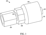
FIG. 1 illustrates an embodiment of a hose fitting in a perspective view, in accordance with the disclosure; and, -
FIGS. 2A and 2B depict a stem useful in some fitting embodiments, in a partial cross-sectional view (FIG. 2A ), and a side cross-sectional view (FIG. 2B ), in accordance with the disclosure. - The following description of the variations is merely illustrative in nature and is in no way intended to limit the scope of the disclosure, its application, or uses. The description is presented herein solely for the purpose of illustrating the various embodiments of the disclosure and should not be construed as a limitation to the scope and applicability of the disclosure. In the summary of the disclosure and this detailed description, each numerical value should be read once as modified by the term "about" (unless already expressly so modified), and then read again as not so modified unless otherwise indicated in context. Also, in the summary of the disclosure and this detailed description, it should be understood that a value range listed or described as being useful, suitable, or the like, is intended that any and every value within the range, including the end points, is to be considered as having been stated. For example, "a range of from 1 to 10" is to be read as indicating each and every possible number along the continuum between about 1 and about 10. Thus, even if specific data points within the range, or even no data points within the range, are explicitly identified or refer to only a few specific, it is to be understood that inventors appreciate and understand that any and all data points within the range are to be considered to have been specified, and that inventors had possession of the entire range and all points within the range.
- Unless expressly stated to the contrary, "or" refers to an inclusive or and not to an exclusive or. For example, a condition A or B is satisfied by anyone of the following: A is true (or present) and B is false (or not present), A is false (or not present) and B is true (or present), and both A and B are true (or present).
- In addition, use of the "a" or "an" are employed to describe elements and components of the embodiments herein. This is done merely for convenience and to give a general sense of concepts according to the disclosure. This description should be read to include one or at least one and the singular also includes the plural unless otherwise stated.
- The terminology and phraseology used herein is for descriptive purposes and should not be construed as limiting in scope. Language such as "including," "comprising," "having," "containing," or "involving," and variations thereof, is intended to be broad and encompass the subject matter listed thereafter, equivalents, and additional subject matter not recited.
- Also, as used herein any references to "one embodiment" or "an embodiment" means that a particular element, feature, structure, or characteristic described in connection with the embodiment is included in at least one embodiment. The appearances of the phrase "in one embodiment" in various places in the specification are not necessarily referring to the same embodiment.
- According to some aspects of the disclosure, a hose fitting includes a swivel tube nut which is incorporated onto the stem of the fitting without additional brazing or crimping operations. Also, the stem is one solid piece of metallic material, which better avoids potential leaks, which can occur at a brazed or crimped connection. Using a swivel tube nut in place of a crimp-on nut, also increases the maximum rated torque value of the swivel tube nut.
- Furthermore, an octagonal wrench surface is forged into the ferrule portion of the fitting, and thereafter, the ferrule is pre-crimped onto the stem of the fitting. This is achieved by forging the octagonal wrench surface shape into the ferrule when it is first made, and thereafter, aligning crimp dies with the eight wrench surface flats on the ferrule to crimp the final amount thus fully staking the ferrule to the stem. Forging the octagonal wrench surface into the ferrule in a first process, substantially or completely forms the octagonal shape and requires only a small amount of crimping is required to attach ferrule to the stem. In some cases, knurling or grooving the stem in the latch area where the ferrule engages the stem, may further improve the connection of the ferrule and the stem, which in turn, may prevent the ferrule from rotating around the stem when torque is applied to the flats on the ferrule.
- Furthermore, as six sided hexagonal has less wrench flats than an eight sided design, an eight sided octagonal shape has more axial locations for the wrench to engage making it easier to install on a hose or a manifold.
- Some aspects of the disclosure also involve the use of smaller, than typical, swivel tube nuts, as well as stems which may be machined from smaller round bar stock to reduce the amount of steel removed during machining.
- Now referencing
FIG. 1 , which illustrates an embodiment of a hose fitting in a perspective view, in accordance with the disclosure. Fitting 100 includes at least three basic components, which arestem 102,swivel tube nut 104, andferrule 106.Swivel tube nut 104 may move freely around the outside ofstem 102 thus allowing a threaded inner surface ofswivel tube nut 104 to engage a threaded surface of a manifold (not shown), or other apparatus, and be sealingly secured thereto.Stem 102 includes features which enable theswivel tube nut 104 to be retained on thestem 102, as well as forming a sealing connection, as described in greater detail below. -
Ferrule 106 includesoctagonal wrench surface 108 which is forged intoferrule 106 prior to being mated withstem 102. After mountingswivel tube nut 104 ontostem 102, an end ofstem 102 is disposed throughferrule 106, and extends through opening 110 offerrule 106. Thereafter,octagonal wrench surface 108 is crimped on a surface ofstem 102 to sealingsecure stem 102 withferrule 106.Stem 102 may include features on the outer surface, in the connection region, to further enable a high torque resistant sealed connection withferrule 106, as described in greater detail below. Opening 110 offerrule 106 is used to accept a hose end (not shown), which is sealingly connected overstem 102 and withinferrule 106. -
FIGS. 2A and 2B depict one embodiment of a stem, functioning asstem 102 inFIG. 1 , which useful in some fitting embodiments, in a partial cross-sectional viewFIG. 2A , and a side cross-sectional viewFIG. 2B .Stem 202 defines acenter axis 204 andfluid conduit 206 there through, for transfer of fluid under pressure.First end 208 ofstem 202 sealingly engages an inner diameter of a hose (not shown), and may include features such as barbs 210 (three shown) for retaining the hose there.Stem 202 also includessecond end 212 with raisedshoulder 214 for receiving and retaining a swivel tube nut, such asswivel tube nut 104 described above.Stem 202 further includescrimp region 216 disposed betweenfirst end 208 andsecond end 212 for sealingmating stem 202 with an octagonal wrench end of a ferrule (such asferrule 106 described above), upon crimping the ferrule ontostem 202. In some aspects, crimpregion 216 includes knurls and/or raisedgrooves 218 for further securing the connection betweenstem 202 and the ferrule. - The foregoing description of the embodiments has been provided for purposes of illustration and description. Example embodiments are provided so that this disclosure will be sufficiently thorough. Numerous specific details are set forth such as examples of specific components, devices, and methods, to provide a thorough understanding of embodiments of the disclosure, but are not intended to be exhaustive or to limit the disclosure. Variations departure from the disclosure, as long as they fall within the scope of the appended claims.
- Also, in some example embodiments, well-known processes, well-known device structures, and well-known technologies are not described in detail. Further, it will be readily apparent to those of skill in the art that in the design, manufacture, and operation of apparatus to achieve that described in the disclosure, variations in apparatus design, construction, condition, erosion of components, and gaps between components may present, for example.
- Although the terms first, second, third, etc. may be used herein to describe various elements, components, regions, layers and/or sections, these elements, components, regions, layers and/or sections should not be limited by these terms. These terms may be only used to distinguish one element, component, region, layer or section from another region, layer or section. Terms such as "first," "second," and other numerical terms when used herein do not imply a sequence or order unless clearly indicated by the context. Thus, a first element, component, region, layer or section discussed below could be termed a second element, component, region, layer or section without departing from the teachings of the example embodiments.
- Spatially relative terms, such as "inner," "outer," "beneath," "below," "lower," "above," "upper," and the like, may be used herein for ease of description to describe one element or feature's relationship to another element(s) or feature(s) as illustrated in the figures. Spatially relative terms may be intended to encompass different orientations of the device in use or operation in addition to the orientation depicted in the figures. For example, if the device in the figures is turned over, elements described as "below" or "beneath" other elements or features would then be oriented "above" the other elements or features. Thus, the example term "below" can encompass both an orientation of above and below. The device may be otherwise oriented (rotated 90 degrees or at other orientations) and the spatially relative descriptors used herein interpreted accordingly.
- Although a few embodiments of the disclosure have been described in detail above, those of ordinary skill in the art will readily appreciate that many modifications as long as they fall within the scope of the appended claims.
Claims (11)
- A method of making a hose fitting (100), comprising:- providing a stem (102, 202) comprising a fluid conduit (206) there through, a first end (208), a second end (212) with a raised shoulder (214), and a crimp region (216) disposed between the first end (208) and the second end (212);- providing and placing a swivel tube nut (104) over the stem (102, 202), wherein the swivel tube nut (104) is retained on the stem (102, 202)-the by the raised shoulder (214);- placing a ferrule (106) over the first end (208) of the stem (102, 201), wherein the ferrule (106) comprises a partially or fully formed octagonal wrench surface (108) and wherein the ferrule (106) has an opening (110), which is used to accept a hose end; and,- pre-crimping the ferrule (106) at the octagonal wrench surface (108) onto the crimp region (216) of the stem (102, 202), wherein the octagonal wrench surface (108) is forged into the ferrule (106) before the ferrule (108) at the octagonal wrench surface (108) is pre-crimped onto the crimp region (216) of the stem (102, 202).
- The method according to claim 1, wherein the pre-crimping is conducted using a crimp die tool.
- The method according to claim 2, wherein the crimp die tool includes at least two die pieces engaging the octagonal wrench surface (108) of the ferrule (106).
- The method according to claim 3, wherein the crimp die tool includes at least four die pieces engaging the octagonal wrench surface (108) of the ferrule (106).
- The method according to claim 4, wherein the crimp die tool includes at least eight die pieces engaging the octagonal wrench surface (108) of the ferrule (106).
- The method according to claim 1, wherein the crimp region (216) comprises one or more of knurls and raised grooves (218) for mating with the ferrule (106).
- The method according to claim 1, wherein the hose fitting (100) consists of the swivel tube nut (104), the ferrule (106) and the stem (102, 202).
- The method according to claim 1, wherein the swivel tube nut (104) is securely connected to the stem (102, 202) in a process which is devoid of brazing.
- The method according to claim 1, wherein the stem (102, 202) is formed from one solid piece of metallic material.
- The method according to claim 1, wherein the stem (102, 202) comprises barbs (210) for sealingly engaging an inner diameter of a hose.
- The method according to claim 1 further comprising sealingly securing a hose to the ferrule (106) and the stem (102, 202).
Applications Claiming Priority (1)
| Application Number | Priority Date | Filing Date | Title |
|---|---|---|---|
| US15/817,328 US10576525B2 (en) | 2017-11-20 | 2017-11-20 | Eight sided forged ferrule staking crimped fitting and method of manufacture thereof |
Publications (2)
| Publication Number | Publication Date |
|---|---|
| EP3486541A1 EP3486541A1 (en) | 2019-05-22 |
| EP3486541B1 true EP3486541B1 (en) | 2023-08-02 |
Family
ID=64362374
Family Applications (1)
| Application Number | Title | Priority Date | Filing Date |
|---|---|---|---|
| EP18206909.6A Active EP3486541B1 (en) | 2017-11-20 | 2018-11-19 | Method of manufacturing an eight sided forged ferrule staking crimped fitting |
Country Status (3)
| Country | Link |
|---|---|
| US (1) | US10576525B2 (en) |
| EP (1) | EP3486541B1 (en) |
| CN (1) | CN109812636B (en) |
Families Citing this family (2)
| Publication number | Priority date | Publication date | Assignee | Title |
|---|---|---|---|---|
| US20200271259A1 (en) * | 2019-02-21 | 2020-08-27 | Andrew Charles Abrams | Safety System for High Pressure Conduits |
| US11333281B1 (en) * | 2019-12-13 | 2022-05-17 | Brunswick Corporation | Hose fitting and hose assembly for marine vehicles |
Family Cites Families (22)
| Publication number | Priority date | Publication date | Assignee | Title |
|---|---|---|---|---|
| US2177095A (en) * | 1936-02-15 | 1939-10-24 | Cowles Irving | Flexible conduit and coupling therefor and method of making same |
| US2211622A (en) * | 1937-02-23 | 1940-08-13 | Weatherhead Corp | Forming machine |
| US2479499A (en) * | 1945-01-01 | 1949-08-16 | Tecalemit Ltd | Coupling for rubber fabric, and like hoses |
| US2496037A (en) * | 1947-05-10 | 1950-01-31 | Weatherhead Co | Composite hose end |
| US2570477A (en) * | 1948-03-31 | 1951-10-09 | Weatherhead Co | Hose coupling |
| US2848254A (en) * | 1950-05-01 | 1958-08-19 | Millar John Humphrey | End fittings for flexible metallic hose |
| US3512810A (en) * | 1969-05-22 | 1970-05-19 | Resistoflex Corp | Hose fitting having a deformable socket |
| US4804212A (en) * | 1986-11-06 | 1989-02-14 | Stratoflex, Inc. | Crimped hose fitting |
| TW375230U (en) * | 1999-01-13 | 1999-11-21 | Hong-Yue Huang | Hydraulic adapters which help to prevent the broken of the inner wall of the oil tube from being scratched during installation |
| CN2396255Y (en) * | 1999-11-02 | 2000-09-13 | 黄宏岳 | Oil pressure connector |
| US20040104572A1 (en) | 2002-11-26 | 2004-06-03 | Gilbreath Donald R. | Hydraulic hose fitting and method |
| US6764106B1 (en) * | 2003-01-23 | 2004-07-20 | Parker-Hannifin Corporation | Cold form hex shell |
| JP4000482B2 (en) * | 2004-09-21 | 2007-10-31 | ニッタ・ムアー株式会社 | Attaching ring or socket to nipple in hose joint |
| USD577795S1 (en) | 2005-07-19 | 2008-09-30 | Parker-Hannifin Corporation | Hose fitting having a non-crimped hex shell mounted on a formed tube |
| US20080185840A1 (en) | 2007-02-07 | 2008-08-07 | Eric Menor | Hex swaged fluid coupling and method of making same |
| US8360479B2 (en) | 2008-11-20 | 2013-01-29 | The Gates Corporation | Crimpable or swageable fluid power ferrules, couplings, systems and methods |
| US9857008B2 (en) | 2008-11-20 | 2018-01-02 | Gates Corporation | Crimpable or swageable fluid power ferrules, couplings, systems and methods employing torque communication |
| US8282138B2 (en) | 2008-12-18 | 2012-10-09 | Rostra Tool Company | Crimp ring |
| US9909699B2 (en) | 2011-03-17 | 2018-03-06 | Jay G. Bernhardt | Garden hose with spiral guard |
| USD737127S1 (en) | 2014-02-12 | 2015-08-25 | David Hong Yeh | Coupling |
| USD777565S1 (en) | 2014-02-12 | 2017-01-31 | David Hong Yeh | Connector |
| US11143445B2 (en) | 2015-04-01 | 2021-10-12 | Uniweld Products, Inc. | Refrigeration hose with multiple access points and method of evacuating an air conditioning or refrigeration unit using the same |
-
2017
- 2017-11-20 US US15/817,328 patent/US10576525B2/en active Active
-
2018
- 2018-11-19 EP EP18206909.6A patent/EP3486541B1/en active Active
- 2018-11-20 CN CN201811382326.XA patent/CN109812636B/en active Active
Also Published As
| Publication number | Publication date |
|---|---|
| CN109812636A (en) | 2019-05-28 |
| EP3486541A1 (en) | 2019-05-22 |
| US20190151927A1 (en) | 2019-05-23 |
| US10576525B2 (en) | 2020-03-03 |
| CN109812636B (en) | 2021-05-18 |
Similar Documents
| Publication | Publication Date | Title |
|---|---|---|
| US10415731B2 (en) | Six sided forged ferrule staking crimped fitting and method of manufacture thereof | |
| US8943668B2 (en) | Hex swaged fluid coupling and method of making same | |
| AU2012362443B2 (en) | Refrigeration line set fitting and method of using the same to join refrigeration lines to each other | |
| US20110204624A1 (en) | Universal connection socket | |
| WO2018190994A1 (en) | Hose fitting with threaded forged ferrule and stem | |
| WO2016033068A1 (en) | Heat exchanger and method of assembling the same | |
| EP3115655B1 (en) | Integrated metal c-seal with threaded adapter | |
| EP3486541A1 (en) | Eight sided forged ferrule staking crimped fitting and method of manufacture thereof | |
| EP1567799B1 (en) | Hydraulic hose fitting | |
| CN100554748C (en) | Fitting for pipes and tubes and method of assembling the fitting | |
| US20060022454A1 (en) | Ring for visually determining the crimped status of a coupling for tubes | |
| US20090145503A1 (en) | Quick connect feature for a fluid connection | |
| US6453539B1 (en) | Metal tube coupling arrangement and method of manufacture | |
| CN113039384B (en) | Mechanical locking end screw arrangement | |
| CA2800360C (en) | Refrigeration line set fitting and method of using the same to join refrigeration lines to each other | |
| WO2024057587A1 (en) | Crimping connector, method for manufacturing hose assembly, and hose assembly | |
| JP2008115889A (en) | Hose coupling and manufacturing method thereof |
Legal Events
| Date | Code | Title | Description |
|---|---|---|---|
| PUAI | Public reference made under article 153(3) epc to a published international application that has entered the european phase |
Free format text: ORIGINAL CODE: 0009012 |
|
| STAA | Information on the status of an ep patent application or granted ep patent |
Free format text: STATUS: THE APPLICATION HAS BEEN PUBLISHED |
|
| AK | Designated contracting states |
Kind code of ref document: A1 Designated state(s): AL AT BE BG CH CY CZ DE DK EE ES FI FR GB GR HR HU IE IS IT LI LT LU LV MC MK MT NL NO PL PT RO RS SE SI SK SM TR |
|
| AX | Request for extension of the european patent |
Extension state: BA ME |
|
| STAA | Information on the status of an ep patent application or granted ep patent |
Free format text: STATUS: REQUEST FOR EXAMINATION WAS MADE |
|
| 17P | Request for examination filed |
Effective date: 20191122 |
|
| RBV | Designated contracting states (corrected) |
Designated state(s): AL AT BE BG CH CY CZ DE DK EE ES FI FR GB GR HR HU IE IS IT LI LT LU LV MC MK MT NL NO PL PT RO RS SE SI SK SM TR |
|
| RAP1 | Party data changed (applicant data changed or rights of an application transferred) |
Owner name: CONTITECH USA, INC. |
|
| STAA | Information on the status of an ep patent application or granted ep patent |
Free format text: STATUS: EXAMINATION IS IN PROGRESS |
|
| 17Q | First examination report despatched |
Effective date: 20210610 |
|
| GRAP | Despatch of communication of intention to grant a patent |
Free format text: ORIGINAL CODE: EPIDOSNIGR1 |
|
| STAA | Information on the status of an ep patent application or granted ep patent |
Free format text: STATUS: GRANT OF PATENT IS INTENDED |
|
| INTG | Intention to grant announced |
Effective date: 20230330 |
|
| GRAS | Grant fee paid |
Free format text: ORIGINAL CODE: EPIDOSNIGR3 |
|
| GRAA | (expected) grant |
Free format text: ORIGINAL CODE: 0009210 |
|
| STAA | Information on the status of an ep patent application or granted ep patent |
Free format text: STATUS: THE PATENT HAS BEEN GRANTED |
|
| AK | Designated contracting states |
Kind code of ref document: B1 Designated state(s): AL AT BE BG CH CY CZ DE DK EE ES FI FR GB GR HR HU IE IS IT LI LT LU LV MC MK MT NL NO PL PT RO RS SE SI SK SM TR |
|
| P01 | Opt-out of the competence of the unified patent court (upc) registered |
Effective date: 20230623 |
|
| REG | Reference to a national code |
Ref country code: GB Ref legal event code: FG4D |
|
| REG | Reference to a national code |
Ref country code: CH Ref legal event code: EP |
|
| REG | Reference to a national code |
Ref country code: DE Ref legal event code: R096 Ref document number: 602018054431 Country of ref document: DE |
|
| REG | Reference to a national code |
Ref country code: IE Ref legal event code: FG4D |
|
| REG | Reference to a national code |
Ref country code: LT Ref legal event code: MG9D |
|
| REG | Reference to a national code |
Ref country code: NL Ref legal event code: MP Effective date: 20230802 |
|
| REG | Reference to a national code |
Ref country code: AT Ref legal event code: MK05 Ref document number: 1595120 Country of ref document: AT Kind code of ref document: T Effective date: 20230802 |
|
| PG25 | Lapsed in a contracting state [announced via postgrant information from national office to epo] |
Ref country code: GR Free format text: LAPSE BECAUSE OF FAILURE TO SUBMIT A TRANSLATION OF THE DESCRIPTION OR TO PAY THE FEE WITHIN THE PRESCRIBED TIME-LIMIT Effective date: 20231103 |
|
| PG25 | Lapsed in a contracting state [announced via postgrant information from national office to epo] |
Ref country code: IS Free format text: LAPSE BECAUSE OF FAILURE TO SUBMIT A TRANSLATION OF THE DESCRIPTION OR TO PAY THE FEE WITHIN THE PRESCRIBED TIME-LIMIT Effective date: 20231202 |
|
| PG25 | Lapsed in a contracting state [announced via postgrant information from national office to epo] |
Ref country code: SE Free format text: LAPSE BECAUSE OF FAILURE TO SUBMIT A TRANSLATION OF THE DESCRIPTION OR TO PAY THE FEE WITHIN THE PRESCRIBED TIME-LIMIT Effective date: 20230802 Ref country code: RS Free format text: LAPSE BECAUSE OF FAILURE TO SUBMIT A TRANSLATION OF THE DESCRIPTION OR TO PAY THE FEE WITHIN THE PRESCRIBED TIME-LIMIT Effective date: 20230802 Ref country code: PT Free format text: LAPSE BECAUSE OF FAILURE TO SUBMIT A TRANSLATION OF THE DESCRIPTION OR TO PAY THE FEE WITHIN THE PRESCRIBED TIME-LIMIT Effective date: 20231204 Ref country code: NO Free format text: LAPSE BECAUSE OF FAILURE TO SUBMIT A TRANSLATION OF THE DESCRIPTION OR TO PAY THE FEE WITHIN THE PRESCRIBED TIME-LIMIT Effective date: 20231102 Ref country code: NL Free format text: LAPSE BECAUSE OF FAILURE TO SUBMIT A TRANSLATION OF THE DESCRIPTION OR TO PAY THE FEE WITHIN THE PRESCRIBED TIME-LIMIT Effective date: 20230802 Ref country code: LV Free format text: LAPSE BECAUSE OF FAILURE TO SUBMIT A TRANSLATION OF THE DESCRIPTION OR TO PAY THE FEE WITHIN THE PRESCRIBED TIME-LIMIT Effective date: 20230802 Ref country code: LT Free format text: LAPSE BECAUSE OF FAILURE TO SUBMIT A TRANSLATION OF THE DESCRIPTION OR TO PAY THE FEE WITHIN THE PRESCRIBED TIME-LIMIT Effective date: 20230802 Ref country code: IS Free format text: LAPSE BECAUSE OF FAILURE TO SUBMIT A TRANSLATION OF THE DESCRIPTION OR TO PAY THE FEE WITHIN THE PRESCRIBED TIME-LIMIT Effective date: 20231202 Ref country code: HR Free format text: LAPSE BECAUSE OF FAILURE TO SUBMIT A TRANSLATION OF THE DESCRIPTION OR TO PAY THE FEE WITHIN THE PRESCRIBED TIME-LIMIT Effective date: 20230802 Ref country code: GR Free format text: LAPSE BECAUSE OF FAILURE TO SUBMIT A TRANSLATION OF THE DESCRIPTION OR TO PAY THE FEE WITHIN THE PRESCRIBED TIME-LIMIT Effective date: 20231103 Ref country code: FI Free format text: LAPSE BECAUSE OF FAILURE TO SUBMIT A TRANSLATION OF THE DESCRIPTION OR TO PAY THE FEE WITHIN THE PRESCRIBED TIME-LIMIT Effective date: 20230802 Ref country code: AT Free format text: LAPSE BECAUSE OF FAILURE TO SUBMIT A TRANSLATION OF THE DESCRIPTION OR TO PAY THE FEE WITHIN THE PRESCRIBED TIME-LIMIT Effective date: 20230802 |
|
| PG25 | Lapsed in a contracting state [announced via postgrant information from national office to epo] |
Ref country code: PL Free format text: LAPSE BECAUSE OF FAILURE TO SUBMIT A TRANSLATION OF THE DESCRIPTION OR TO PAY THE FEE WITHIN THE PRESCRIBED TIME-LIMIT Effective date: 20230802 |
|
| PG25 | Lapsed in a contracting state [announced via postgrant information from national office to epo] |
Ref country code: ES Free format text: LAPSE BECAUSE OF FAILURE TO SUBMIT A TRANSLATION OF THE DESCRIPTION OR TO PAY THE FEE WITHIN THE PRESCRIBED TIME-LIMIT Effective date: 20230802 |
|
| PG25 | Lapsed in a contracting state [announced via postgrant information from national office to epo] |
Ref country code: SM Free format text: LAPSE BECAUSE OF FAILURE TO SUBMIT A TRANSLATION OF THE DESCRIPTION OR TO PAY THE FEE WITHIN THE PRESCRIBED TIME-LIMIT Effective date: 20230802 Ref country code: RO Free format text: LAPSE BECAUSE OF FAILURE TO SUBMIT A TRANSLATION OF THE DESCRIPTION OR TO PAY THE FEE WITHIN THE PRESCRIBED TIME-LIMIT Effective date: 20230802 Ref country code: ES Free format text: LAPSE BECAUSE OF FAILURE TO SUBMIT A TRANSLATION OF THE DESCRIPTION OR TO PAY THE FEE WITHIN THE PRESCRIBED TIME-LIMIT Effective date: 20230802 Ref country code: EE Free format text: LAPSE BECAUSE OF FAILURE TO SUBMIT A TRANSLATION OF THE DESCRIPTION OR TO PAY THE FEE WITHIN THE PRESCRIBED TIME-LIMIT Effective date: 20230802 Ref country code: DK Free format text: LAPSE BECAUSE OF FAILURE TO SUBMIT A TRANSLATION OF THE DESCRIPTION OR TO PAY THE FEE WITHIN THE PRESCRIBED TIME-LIMIT Effective date: 20230802 Ref country code: CZ Free format text: LAPSE BECAUSE OF FAILURE TO SUBMIT A TRANSLATION OF THE DESCRIPTION OR TO PAY THE FEE WITHIN THE PRESCRIBED TIME-LIMIT Effective date: 20230802 Ref country code: SK Free format text: LAPSE BECAUSE OF FAILURE TO SUBMIT A TRANSLATION OF THE DESCRIPTION OR TO PAY THE FEE WITHIN THE PRESCRIBED TIME-LIMIT Effective date: 20230802 |
|
| REG | Reference to a national code |
Ref country code: DE Ref legal event code: R097 Ref document number: 602018054431 Country of ref document: DE |
|
| PG25 | Lapsed in a contracting state [announced via postgrant information from national office to epo] |
Ref country code: IT Free format text: LAPSE BECAUSE OF FAILURE TO SUBMIT A TRANSLATION OF THE DESCRIPTION OR TO PAY THE FEE WITHIN THE PRESCRIBED TIME-LIMIT Effective date: 20230802 |
|
| PLBE | No opposition filed within time limit |
Free format text: ORIGINAL CODE: 0009261 |
|
| STAA | Information on the status of an ep patent application or granted ep patent |
Free format text: STATUS: NO OPPOSITION FILED WITHIN TIME LIMIT |
|
| REG | Reference to a national code |
Ref country code: CH Ref legal event code: PL |
|
| PG25 | Lapsed in a contracting state [announced via postgrant information from national office to epo] |
Ref country code: MC Free format text: LAPSE BECAUSE OF FAILURE TO SUBMIT A TRANSLATION OF THE DESCRIPTION OR TO PAY THE FEE WITHIN THE PRESCRIBED TIME-LIMIT Effective date: 20230802 |
|
| 26N | No opposition filed |
Effective date: 20240503 |
|
| PG25 | Lapsed in a contracting state [announced via postgrant information from national office to epo] |
Ref country code: LU Free format text: LAPSE BECAUSE OF NON-PAYMENT OF DUE FEES Effective date: 20231119 |
|
| PG25 | Lapsed in a contracting state [announced via postgrant information from national office to epo] |
Ref country code: CH Free format text: LAPSE BECAUSE OF NON-PAYMENT OF DUE FEES Effective date: 20231130 |
|
| PG25 | Lapsed in a contracting state [announced via postgrant information from national office to epo] |
Ref country code: MC Free format text: LAPSE BECAUSE OF FAILURE TO SUBMIT A TRANSLATION OF THE DESCRIPTION OR TO PAY THE FEE WITHIN THE PRESCRIBED TIME-LIMIT Effective date: 20230802 Ref country code: LU Free format text: LAPSE BECAUSE OF NON-PAYMENT OF DUE FEES Effective date: 20231119 Ref country code: CH Free format text: LAPSE BECAUSE OF NON-PAYMENT OF DUE FEES Effective date: 20231130 Ref country code: SI Free format text: LAPSE BECAUSE OF FAILURE TO SUBMIT A TRANSLATION OF THE DESCRIPTION OR TO PAY THE FEE WITHIN THE PRESCRIBED TIME-LIMIT Effective date: 20230802 |
|
| REG | Reference to a national code |
Ref country code: BE Ref legal event code: MM Effective date: 20231130 |
|
| REG | Reference to a national code |
Ref country code: IE Ref legal event code: MM4A |
|
| PG25 | Lapsed in a contracting state [announced via postgrant information from national office to epo] |
Ref country code: IE Free format text: LAPSE BECAUSE OF NON-PAYMENT OF DUE FEES Effective date: 20231119 |
|
| PG25 | Lapsed in a contracting state [announced via postgrant information from national office to epo] |
Ref country code: BE Free format text: LAPSE BECAUSE OF NON-PAYMENT OF DUE FEES Effective date: 20231130 |
|
| PG25 | Lapsed in a contracting state [announced via postgrant information from national office to epo] |
Ref country code: IE Free format text: LAPSE BECAUSE OF NON-PAYMENT OF DUE FEES Effective date: 20231119 Ref country code: BE Free format text: LAPSE BECAUSE OF NON-PAYMENT OF DUE FEES Effective date: 20231130 |
|
| PG25 | Lapsed in a contracting state [announced via postgrant information from national office to epo] |
Ref country code: BG Free format text: LAPSE BECAUSE OF FAILURE TO SUBMIT A TRANSLATION OF THE DESCRIPTION OR TO PAY THE FEE WITHIN THE PRESCRIBED TIME-LIMIT Effective date: 20230802 |
|
| PG25 | Lapsed in a contracting state [announced via postgrant information from national office to epo] |
Ref country code: BG Free format text: LAPSE BECAUSE OF FAILURE TO SUBMIT A TRANSLATION OF THE DESCRIPTION OR TO PAY THE FEE WITHIN THE PRESCRIBED TIME-LIMIT Effective date: 20230802 |
|
| PG25 | Lapsed in a contracting state [announced via postgrant information from national office to epo] |
Ref country code: CY Free format text: LAPSE BECAUSE OF FAILURE TO SUBMIT A TRANSLATION OF THE DESCRIPTION OR TO PAY THE FEE WITHIN THE PRESCRIBED TIME-LIMIT; INVALID AB INITIO Effective date: 20181119 |
|
| PG25 | Lapsed in a contracting state [announced via postgrant information from national office to epo] |
Ref country code: HU Free format text: LAPSE BECAUSE OF FAILURE TO SUBMIT A TRANSLATION OF THE DESCRIPTION OR TO PAY THE FEE WITHIN THE PRESCRIBED TIME-LIMIT; INVALID AB INITIO Effective date: 20181119 |
|
| PG25 | Lapsed in a contracting state [announced via postgrant information from national office to epo] |
Ref country code: TR Free format text: LAPSE BECAUSE OF FAILURE TO SUBMIT A TRANSLATION OF THE DESCRIPTION OR TO PAY THE FEE WITHIN THE PRESCRIBED TIME-LIMIT Effective date: 20230802 |
|
| PGFP | Annual fee paid to national office [announced via postgrant information from national office to epo] |
Ref country code: DE Payment date: 20251130 Year of fee payment: 8 |
|
| PGFP | Annual fee paid to national office [announced via postgrant information from national office to epo] |
Ref country code: GB Payment date: 20251121 Year of fee payment: 8 |
|
| PGFP | Annual fee paid to national office [announced via postgrant information from national office to epo] |
Ref country code: FR Payment date: 20251126 Year of fee payment: 8 |