EP1567799B1 - Hydraulic hose fitting - Google Patents
Hydraulic hose fitting Download PDFInfo
- Publication number
- EP1567799B1 EP1567799B1 EP03790109A EP03790109A EP1567799B1 EP 1567799 B1 EP1567799 B1 EP 1567799B1 EP 03790109 A EP03790109 A EP 03790109A EP 03790109 A EP03790109 A EP 03790109A EP 1567799 B1 EP1567799 B1 EP 1567799B1
- Authority
- EP
- European Patent Office
- Prior art keywords
- collar
- fitting
- support portion
- ferrule
- hose
- Prior art date
- Legal status (The legal status is an assumption and is not a legal conclusion. Google has not performed a legal analysis and makes no representation as to the accuracy of the status listed.)
- Expired - Lifetime
Links
- 230000013011 mating Effects 0.000 claims abstract description 16
- 238000004891 communication Methods 0.000 claims abstract description 14
- 230000008878 coupling Effects 0.000 claims description 7
- 238000010168 coupling process Methods 0.000 claims description 7
- 238000005859 coupling reaction Methods 0.000 claims description 7
- 238000013461 design Methods 0.000 description 8
- 238000000034 method Methods 0.000 description 5
- 238000004519 manufacturing process Methods 0.000 description 4
- 230000008569 process Effects 0.000 description 4
- 238000005219 brazing Methods 0.000 description 3
- 210000002445 nipple Anatomy 0.000 description 3
- 238000006073 displacement reaction Methods 0.000 description 2
- 239000012530 fluid Substances 0.000 description 2
- 230000014759 maintenance of location Effects 0.000 description 2
- 230000000087 stabilizing effect Effects 0.000 description 2
- 230000008901 benefit Effects 0.000 description 1
- 238000002788 crimping Methods 0.000 description 1
- 230000006872 improvement Effects 0.000 description 1
- 238000012986 modification Methods 0.000 description 1
- 230000004048 modification Effects 0.000 description 1
- 238000012546 transfer Methods 0.000 description 1
Images


Classifications
-
- F—MECHANICAL ENGINEERING; LIGHTING; HEATING; WEAPONS; BLASTING
- F16—ENGINEERING ELEMENTS AND UNITS; GENERAL MEASURES FOR PRODUCING AND MAINTAINING EFFECTIVE FUNCTIONING OF MACHINES OR INSTALLATIONS; THERMAL INSULATION IN GENERAL
- F16L—PIPES; JOINTS OR FITTINGS FOR PIPES; SUPPORTS FOR PIPES, CABLES OR PROTECTIVE TUBING; MEANS FOR THERMAL INSULATION IN GENERAL
- F16L33/00—Arrangements for connecting hoses to rigid members; Rigid hose-connectors, i.e. single members engaging both hoses
- F16L33/20—Undivided rings, sleeves, or like members contracted on the hose or expanded inside the hose by means of tools; Arrangements using such members
- F16L33/207—Undivided rings, sleeves, or like members contracted on the hose or expanded inside the hose by means of tools; Arrangements using such members only a sleeve being contracted on the hose
- F16L33/2071—Undivided rings, sleeves, or like members contracted on the hose or expanded inside the hose by means of tools; Arrangements using such members only a sleeve being contracted on the hose the sleeve being a separate connecting member
- F16L33/2073—Undivided rings, sleeves, or like members contracted on the hose or expanded inside the hose by means of tools; Arrangements using such members only a sleeve being contracted on the hose the sleeve being a separate connecting member directly connected to the rigid member
- F16L33/2076—Undivided rings, sleeves, or like members contracted on the hose or expanded inside the hose by means of tools; Arrangements using such members only a sleeve being contracted on the hose the sleeve being a separate connecting member directly connected to the rigid member by plastic deformation
-
- F—MECHANICAL ENGINEERING; LIGHTING; HEATING; WEAPONS; BLASTING
- F16—ENGINEERING ELEMENTS AND UNITS; GENERAL MEASURES FOR PRODUCING AND MAINTAINING EFFECTIVE FUNCTIONING OF MACHINES OR INSTALLATIONS; THERMAL INSULATION IN GENERAL
- F16L—PIPES; JOINTS OR FITTINGS FOR PIPES; SUPPORTS FOR PIPES, CABLES OR PROTECTIVE TUBING; MEANS FOR THERMAL INSULATION IN GENERAL
- F16L33/00—Arrangements for connecting hoses to rigid members; Rigid hose-connectors, i.e. single members engaging both hoses
- F16L33/20—Undivided rings, sleeves, or like members contracted on the hose or expanded inside the hose by means of tools; Arrangements using such members
- F16L33/207—Undivided rings, sleeves, or like members contracted on the hose or expanded inside the hose by means of tools; Arrangements using such members only a sleeve being contracted on the hose
- F16L33/2071—Undivided rings, sleeves, or like members contracted on the hose or expanded inside the hose by means of tools; Arrangements using such members only a sleeve being contracted on the hose the sleeve being a separate connecting member
- F16L33/2078—Undivided rings, sleeves, or like members contracted on the hose or expanded inside the hose by means of tools; Arrangements using such members only a sleeve being contracted on the hose the sleeve being a separate connecting member connected to the rigid member via an intermediate element
-
- F—MECHANICAL ENGINEERING; LIGHTING; HEATING; WEAPONS; BLASTING
- F16—ENGINEERING ELEMENTS AND UNITS; GENERAL MEASURES FOR PRODUCING AND MAINTAINING EFFECTIVE FUNCTIONING OF MACHINES OR INSTALLATIONS; THERMAL INSULATION IN GENERAL
- F16L—PIPES; JOINTS OR FITTINGS FOR PIPES; SUPPORTS FOR PIPES, CABLES OR PROTECTIVE TUBING; MEANS FOR THERMAL INSULATION IN GENERAL
- F16L33/00—Arrangements for connecting hoses to rigid members; Rigid hose-connectors, i.e. single members engaging both hoses
- F16L33/22—Arrangements for connecting hoses to rigid members; Rigid hose-connectors, i.e. single members engaging both hoses with means not mentioned in the preceding groups for gripping the hose between inner and outer parts
- F16L33/223—Arrangements for connecting hoses to rigid members; Rigid hose-connectors, i.e. single members engaging both hoses with means not mentioned in the preceding groups for gripping the hose between inner and outer parts the sealing surfaces being pressed together by means of a member, e.g. a swivel nut, screwed on or into one of the joint parts
- F16L33/224—Arrangements for connecting hoses to rigid members; Rigid hose-connectors, i.e. single members engaging both hoses with means not mentioned in the preceding groups for gripping the hose between inner and outer parts the sealing surfaces being pressed together by means of a member, e.g. a swivel nut, screwed on or into one of the joint parts a clamping ring being arranged between the threaded member and the connecting member
-
- F—MECHANICAL ENGINEERING; LIGHTING; HEATING; WEAPONS; BLASTING
- F16—ENGINEERING ELEMENTS AND UNITS; GENERAL MEASURES FOR PRODUCING AND MAINTAINING EFFECTIVE FUNCTIONING OF MACHINES OR INSTALLATIONS; THERMAL INSULATION IN GENERAL
- F16L—PIPES; JOINTS OR FITTINGS FOR PIPES; SUPPORTS FOR PIPES, CABLES OR PROTECTIVE TUBING; MEANS FOR THERMAL INSULATION IN GENERAL
- F16L33/00—Arrangements for connecting hoses to rigid members; Rigid hose-connectors, i.e. single members engaging both hoses
- F16L33/24—Arrangements for connecting hoses to rigid members; Rigid hose-connectors, i.e. single members engaging both hoses with parts screwed directly on or into the hose
Definitions
- This invention relates generally to hydraulic tube and hose couplings. More particularly, it relates to hose end fittings of such couplings. Specifically, it relates to collar and collar support portions of hose end fittings for tube and hose couplings.
- the hose connection portion or fitting can include a tube or stem portion, a collar and optionally a ferrule.
- the collar fits about a middle region of the tube portion and is compressed or staked to affix it in place.
- the ferrule if present, can also be staked about a portion of the collar to affix it in place.
- the tube portion has a hose insert portion, which is inserted into the open end of the hose.
- the ferrule is then compressed or crimped about the hose end containing the insert trapping the hose between the ferrule and the hose insert portion. This causes all portions to be permanently sealed and affixed to prevent axial or rotational movement of the hose end.
- the hose connection fitting further may have a mating connection portion of many styles, including threaded, press-on, male, and female. Certain mating connection portion designs require the use of collars to make the manufacture of the associated fittings possible. Mating this mating connection portion with the cooperating portion of the fitting connected to the subject fixture, machinery or equipment completes the particular hydraulic assembly that allows a fluid-tight transfer of fluid.
- the collar will commonly include wrench flats to stabilize the fitting from rotating as the mating connection portion is tightened to complete the mating with the cooperating portion of the fixture fitting.
- Ferrules are included in designs where the fitting and hose operate under severe axial loads that can be the result of high operating pressures or tensile loads imparted to the hose.
- EP0151017 discusses a multi-piece hose stem with a nipple and external sleeve that defines a ferrule locking collar, the sleeve attached to the nipple by a preferred method of radially expanding a portion of the nipple to contact and hold the sleeve.
- the present invention has as an object the provision of a hydraulic fitting with the combination of characteristics including resistance of the collar to twisting relative to the stem when torque is applied to the wrenching portion of the collar and to axial displacement relative to the stem when loaded by the hose.
- the present invention is a hydraulic fitting of the type having a stem including a hose insert portion, and a collar support portion.
- the fitting further has a mating connection portion, and a collar having, a torque communication portion, a ferrule support portion, and an inner periphery extending through the ferrule support portion and the torque communication portion.
- the fitting is improved by the collar support portion including knurling and an axial stop ring.
- the torque communication portion of the collar is staked such that the inner periphery extending through the torque communication portion communicates with the knurling of the collar support portion of the stem in a relatively non-rotational manner.
- the ferrule support portion of the collar is staked such that the inner periphery extending through the ferrule support portion communicates with the axial stop ring of the stem in an axial movement limiting manner.
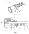
- this hydraulic hose fitting 10 includes stem 12 having barbs 14, over which is placed collar 16 having wrench flats 18. Also placed over stem 12 is nut 20 having nut abutment 44. The process of staking collar 16 upon stem 12 leaves stake marks 22. Greater detail of stem 12 can be viewed in Figures 3 and 4 . Specifically, knurling 24, axial stop ring 26, assembly stop ring 28, ramp 30, and stem abutment 32 are apparent. Greater detail of collar 16 can be viewed in figures 5 and 6 . Specifically, ferrule depression 34, axial retention ridge 36, assembly ridge 38, knurling mating surface 40, and free surface 42 are apparent. Collar 16 can be viewed as having torque communication portion D and ferrule support portion E.
- Assembly of this preferred embodiment includes placing nut 20 over stem 12 until nut abutment 32 becomes near or proximate to stem abutment 44, as depicted. Then, collar 16 is placed over stem 12 until assembly ridge 38 abuts assembly stop ring 28. Assembly stop ring 28 is optional. In some instances, the difference in diameters of barbs 14 and the portion of stem 12 having knurling 24 are to similar to allow assembly stop ring 28 to be distinct. Where assembly stop ring 28 is available and distinct, assembly stop ring 28 and assembly ridge 38, aided by ramp 30, provide easy reference to locate collar 16 upon stem 12.
- the three pieces once assembled in this manner are placed in a swaging tool, of common design (not depicted), having multiple staking dies 46.
- the staking dies commonly number eight.
- the swaging tool presses staking dies 46 against collar 16 on both sides of wrench flats 18 with adequate force to, at once, compress collar 16 to the point where axial retention ridge 36 takes on a diameter smaller than axial stop ring 26 and knurling mating surface 40 is forcefully compressed against knurling 24, as depicted in Figure 2 . This operation is evidenced by the staking marks 22 left behind.
- the fitting can be viewed as having hose insert portion A, collar support portion B, and mating connection portion C.
- hose insert portion A of fitting 10 is inserted into an open end of a hydraulic hose (not depicted).
- the hose is sealingly clamped in place.
- a ferrule 48 is used for this clamping function.
- Ferrule 48 can first be staked upon collar 16 at ferrule depression 34 of ferrule support portion E.
- Ferrule 48 would then be crimped about the connection end of the hose.
- Ferrule 48 can also be crimped upon collar 16 before, after, or during crimping upon the hose.
- the completion of the fluid tight connection involves attachment to a machine or other apparatus (not depicted).
- Such machine or apparatus will have a machine or apparatus fitting (not depicted) adapted to mate with fitting 10.
- Nut 20 of mating connection portion C will be tightly threaded upon the apparatus fitting.
- the tightening will entail applying a wrench to nut 20 to apply tightening torque and applying a wrench to wrench flats 18 to apply stabilizing torque to stem 12 to avoid twisting the hose or fitting 10 within the hose.
- the instant invention allows very substantial stabilizing torque to be applied that heretofore was unavailable on fittings having collars 16 separate from stems 12 that could also support substantial axial loads.
- This preferred embodiment includes free surface 42 on collar 16. This allows simplicity in the staking process by eliminating the need for non-standard six-finger stake dies and eliminating the need for indexing in relation to wrench flats 18. In some cases, this also allows greater space for nut 20 to be retracted while unthreaded from the male threads of an apparatus or machine fitting (not depicted). However, it allows stake marks 22 be visible at torque communication portion D, which may be regarded as unsightly.
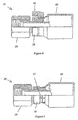
- FIG. 8 depicts another preferred embodiment.
- collar 18 does not include free surface 42. Accordingly, the space available for movement of nut 20 when unthreaded is limited for any given overall length of fitting 10. It has the advantage that the staking process can be applied to wrench flats 18 allowing enough surface area to be involved to preclude leaving the unsightly staking marks 22. However, non-standard six-finger staking dies are required.
- Figure 8 depicts fitting 10 just prior to the staking process and includes ferrule 48 positioned for staking.
- Figure 9 depicts fitting 10 after completion of staking. As with the prior embodiment, this embodiment can be produced with or without ferrule 48.
Landscapes
- Engineering & Computer Science (AREA)
- General Engineering & Computer Science (AREA)
- Mechanical Engineering (AREA)
- Joints That Cut Off Fluids, And Hose Joints (AREA)
- Joints Allowing Movement (AREA)
- Shafts, Cranks, Connecting Bars, And Related Bearings (AREA)
- Rigid Pipes And Flexible Pipes (AREA)
- Fluid-Pressure Circuits (AREA)
- Lining Or Joining Of Plastics Or The Like (AREA)
Abstract
Description
- This invention relates generally to hydraulic tube and hose couplings. More particularly, it relates to hose end fittings of such couplings. Specifically, it relates to collar and collar support portions of hose end fittings for tube and hose couplings.
- Hydraulic couplings are known. The hose connection portion or fitting can include a tube or stem portion, a collar and optionally a ferrule. The collar fits about a middle region of the tube portion and is compressed or staked to affix it in place. The ferrule, if present, can also be staked about a portion of the collar to affix it in place. The tube portion has a hose insert portion, which is inserted into the open end of the hose. The ferrule is then compressed or crimped about the hose end containing the insert trapping the hose between the ferrule and the hose insert portion. This causes all portions to be permanently sealed and affixed to prevent axial or rotational movement of the hose end. The hose connection fitting further may have a mating connection portion of many styles, including threaded, press-on, male, and female. Certain mating connection portion designs require the use of collars to make the manufacture of the associated fittings possible. Mating this mating connection portion with the cooperating portion of the fitting connected to the subject fixture, machinery or equipment completes the particular hydraulic assembly that allows a fluid-tight transfer of fluid.
- For those fittings having threaded mating connection portions, the collar will commonly include wrench flats to stabilize the fitting from rotating as the mating connection portion is tightened to complete the mating with the cooperating portion of the fixture fitting. Ferrules are included in designs where the fitting and hose operate under severe axial loads that can be the result of high operating pressures or tensile loads imparted to the hose.
- There is currently a stake collar design that retains the ferrule on the coupling hose end fitting while supporting a significant longitudinal load. However, this collar design will rotate relative to the stem at fairly low torque values. This collar design is staked on one side of the collar only. Further, a knurl has previously been used in conjunction with an internal spline on a collar to withstand high torque. However, this design cannot be used in cases of have high axial loads where a ferrule is required because it will not support the high axial loads. This collar design is also staked oniy_on one side of the collar. It is also known to braze the collar to the stem. While this produces a fitting with a very secure collar, it is fraught with the manufacturing difficulties brazing introduces and the attendant increase in cost and complexity for its manufacture.
-
EP0151017 discusses a multi-piece hose stem with a nipple and external sleeve that defines a ferrule locking collar, the sleeve attached to the nipple by a preferred method of radially expanding a portion of the nipple to contact and hold the sleeve. - Accordingly, there is a continuing need for a hydraulic fitting having a separate collar that achieves improvement in both the characteristics of resistance of the collar to twisting relative to the stem when torque is applied to the wrenching portion of the collar and to axial displacement relative to the stem when forced by the ferrule reacting to forces imparted by the hose, without the drawbacks of including brazing.
- The present invention has as an object the provision of a hydraulic fitting with the combination of characteristics including resistance of the collar to twisting relative to the stem when torque is applied to the wrenching portion of the collar and to axial displacement relative to the stem when loaded by the hose.
- The present invention is a hydraulic fitting of the type having a stem including a hose insert portion, and a collar support portion. The fitting further has a mating connection portion, and a collar having, a torque communication portion, a ferrule support portion, and an inner periphery extending through the ferrule support portion and the torque communication portion. The fitting is improved by the collar support portion including knurling and an axial stop ring. Further, the torque communication portion of the collar is staked such that the inner periphery extending through the torque communication portion communicates with the knurling of the collar support portion of the stem in a relatively non-rotational manner. Also, the ferrule support portion of the collar is staked such that the inner periphery extending through the ferrule support portion communicates with the axial stop ring of the stem in an axial movement limiting manner.
- The accompanying drawings, which are incorporated in and form part of the specification in which like numerals designate like parts, illustrate preferred embodiments of the present invention and together with the description, serve to explain the principles of the invention. In the drawings:
-
FIG. 1 is a perspective view of a hydraulic fitting of a preferred embodiment; -
FIG. 2 is an elevation of a hydraulic fitting, with one quarter cut-away, of a preferred embodiment; -
FIG. 3 is perspective view, of a stem of a hydraulic fitting, of a preferred embodiment; -
FIG. 4 is an elevation, with one quarter cut-away, of a stem of a preferred embodiment; -
FIG. 5 is perspective view, of a collar of a hydraulic fitting, of a preferred embodiment; -
FIG. 6 is an elevation, with one quarter cut-away, of a collar of a preferred embodiment; -
FIG. 7 is a partial elevation, with one quarter cut away, of a preferred embodiment of a hydraulic fitting including a staking die; -
FIG. 8 is a partial elevation, with one quarter cut away, of another preferred embodiment of a hydraulic fitting including a ferrule and a staking die; and, -
FIG. 9 is an elevation of a hydraulic fitting, with one quarter cut-away, of another preferred embodiment. - Referring to
Figures 1 and 2 , one preferred embodiment of thishydraulic hose fitting 10 includesstem 12 havingbarbs 14, over which is placedcollar 16 havingwrench flats 18. Also placed overstem 12 isnut 20 havingnut abutment 44. The process of stakingcollar 16 uponstem 12 leavesstake marks 22. Greater detail ofstem 12 can be viewed inFigures 3 and 4 . Specifically, knurling 24,axial stop ring 26,assembly stop ring 28,ramp 30, andstem abutment 32 are apparent. Greater detail ofcollar 16 can be viewed infigures 5 and 6 . Specifically,ferrule depression 34,axial retention ridge 36,assembly ridge 38,knurling mating surface 40, andfree surface 42 are apparent.Collar 16 can be viewed as having torque communication portion D and ferrule support portion E. - Assembly of this preferred embodiment includes placing
nut 20 overstem 12 untilnut abutment 32 becomes near or proximate to stem abutment 44, as depicted. Then,collar 16 is placed overstem 12 untilassembly ridge 38 abutsassembly stop ring 28.Assembly stop ring 28 is optional. In some instances, the difference in diameters ofbarbs 14 and the portion ofstem 12 having knurling 24 are to similar to allowassembly stop ring 28 to be distinct. Whereassembly stop ring 28 is available and distinct,assembly stop ring 28 andassembly ridge 38, aided byramp 30, provide easy reference to locatecollar 16 uponstem 12. Referring toFigure 7 , the three pieces once assembled in this manner are placed in a swaging tool, of common design (not depicted), having multiple staking dies 46. For the fitting depicted, the staking dies commonly number eight. The swaging tool presses staking dies 46 againstcollar 16 on both sides ofwrench flats 18 with adequate force to, at once, compresscollar 16 to the point whereaxial retention ridge 36 takes on a diameter smaller thanaxial stop ring 26 and knurlingmating surface 40 is forcefully compressed against knurling 24, as depicted inFigure 2 . This operation is evidenced by thestaking marks 22 left behind. Thus with asingle operation nut 20 is trapped ontostem 12,collar 16 is affixed to stem 12 with a high degree of resistance to rotation uponstem 12 and affixed with a high degree of resistance to being dislodged axially. The result is a hydraulic hose fitting that has been assembled very efficiently and is very robust for applications demanding substantial torque be placed upon the fitting during mating to an apparatus fitting (not depicted) as well as being subjected to substantial axial loads during use. - The fitting can be viewed as having hose insert portion A, collar support portion B, and mating connection portion C. In use, hose insert portion A of fitting 10 is inserted into an open end of a hydraulic hose (not depicted). The hose is sealingly clamped in place. For greatest resistance to the hose being axially separated from fitting 10, a
ferrule 48 is used for this clamping function.Ferrule 48 can first be staked uponcollar 16 atferrule depression 34 of ferrule supportportion E. Ferrule 48 would then be crimped about the connection end of the hose.Ferrule 48 can also be crimped uponcollar 16 before, after, or during crimping upon the hose. The completion of the fluid tight connection involves attachment to a machine or other apparatus (not depicted). Such machine or apparatus will have a machine or apparatus fitting (not depicted) adapted to mate with fitting 10.Nut 20 of mating connection portion C will be tightly threaded upon the apparatus fitting. The tightening will entail applying a wrench tonut 20 to apply tightening torque and applying a wrench towrench flats 18 to apply stabilizing torque to stem 12 to avoid twisting the hose or fitting 10 within the hose. The instant invention allows very substantial stabilizing torque to be applied that heretofore was unavailable onfittings having collars 16 separate from stems 12 that could also support substantial axial loads. - This preferred embodiment includes
free surface 42 oncollar 16. This allows simplicity in the staking process by eliminating the need for non-standard six-finger stake dies and eliminating the need for indexing in relation towrench flats 18. In some cases, this also allows greater space fornut 20 to be retracted while unthreaded from the male threads of an apparatus or machine fitting (not depicted). However, it allows stake marks 22 be visible at torque communication portion D, which may be regarded as unsightly. - Another preferred embodiment is depicted in
Figures 8 and 9 . In this embodiment,collar 18 does not includefree surface 42. Accordingly, the space available for movement ofnut 20 when unthreaded is limited for any given overall length of fitting 10. It has the advantage that the staking process can be applied towrench flats 18 allowing enough surface area to be involved to preclude leaving the unsightly staking marks 22. However, non-standard six-finger staking dies are required.Figure 8 depicts fitting 10 just prior to the staking process and includesferrule 48 positioned for staking.Figure 9 depicts fitting 10 after completion of staking. As with the prior embodiment, this embodiment can be produced with or withoutferrule 48. - The net result of the instant invention are hydraulic fittings having collars that can withstand both substantial torque and axial force, relative to the stem, and do not require brazing in their manufacture.
- The foregoing description and illustrative embodiments of the present invention have been shown on the drawings and described in detail in varying modifications and alternative embodiments. It should be understood, however, that the foregoing description of the invention is exemplary only, and that the scope of the invention is to be limited only to the claims as interpreted in view of the prior art. Moreover, the invention illustratively disclosed herein suitably may be practiced in the absence of any element which is not specifically disclosed herein.
Claims (4)
- An hydraulic fitting (10) of the type having a stem (12) including a hose insert portion (A), and a collar support portion (B), having a mating connection portion (C), and a collar (16) having, a torque communication portion (D), a ferrule support portion (E), and an inner periphery extending through said ferrule support portion (E) and said torque communication portion (D),
characterised by;
said collar support portion (B) including knurling (40) and an axial stop ring;
said torque communication portion (D) being staked such that said inner periphery extending through said torque communication portion (D) communicates with said knurling (24) in a relatively non-rotational manner; and
said ferrule support portion (E) being staked such that said inner periphery extending through said ferrule support portion (E) communicates with said axial stop ring (26) in an axial movement limiting manner. - The hydraulic fitting (10) of claim 1 further comprising a ferrule (48) affixed upon said ferrule support portion (E).
- A hydraulic coupling and hose comprising:a hose end fitting including all the features of the hydraulic fitting (10) as claimed in claim 1;said hose fitted upon said hose end fitting;an apparatus fitting; andsaid apparatus fitting sealingly mated to said mating connection portion (C) of said hose end fitting.
- The hydraulic coupling and hose of claim 3 further comprising a ferrule (48) staked upon said ferrule support portion (E) and said hose crimped under said ferrule (48).
Applications Claiming Priority (3)
| Application Number | Priority Date | Filing Date | Title |
|---|---|---|---|
| US42967902P | 2002-11-26 | 2002-11-26 | |
| US429679P | 2002-11-26 | ||
| PCT/US2003/037891 WO2004048839A1 (en) | 2002-11-26 | 2003-11-26 | Hydraulic hose fitting and method |
Publications (2)
| Publication Number | Publication Date |
|---|---|
| EP1567799A1 EP1567799A1 (en) | 2005-08-31 |
| EP1567799B1 true EP1567799B1 (en) | 2008-11-05 |
Family
ID=32393574
Family Applications (1)
| Application Number | Title | Priority Date | Filing Date |
|---|---|---|---|
| EP03790109A Expired - Lifetime EP1567799B1 (en) | 2002-11-26 | 2003-11-26 | Hydraulic hose fitting |
Country Status (14)
| Country | Link |
|---|---|
| US (1) | US20040104572A1 (en) |
| EP (1) | EP1567799B1 (en) |
| JP (1) | JP4210650B2 (en) |
| KR (1) | KR100697790B1 (en) |
| CN (1) | CN100436918C (en) |
| AT (1) | ATE413557T1 (en) |
| AU (1) | AU2003293117B2 (en) |
| BR (1) | BR0316620A (en) |
| CA (1) | CA2507076C (en) |
| DE (1) | DE60324587D1 (en) |
| MX (1) | MXPA05006778A (en) |
| PL (1) | PL204872B1 (en) |
| TW (1) | TWI231347B (en) |
| WO (1) | WO2004048839A1 (en) |
Families Citing this family (15)
| Publication number | Priority date | Publication date | Assignee | Title |
|---|---|---|---|---|
| US20080061555A1 (en) * | 2005-02-16 | 2008-03-13 | Colin Knight | Flared cone fitting |
| JP2008075807A (en) * | 2006-09-22 | 2008-04-03 | Bridgestone Flowtech Corp | Joint and manufacturing method thereof |
| WO2008141386A1 (en) * | 2007-05-23 | 2008-11-27 | E.R.T.H. Hyd Pty Ltd | Hydraulic hose coupling |
| DE102007026394B4 (en) * | 2007-06-06 | 2010-11-11 | Eaton Fluid Power Gmbh | Tight hose connection |
| CN102125944B (en) * | 2010-11-29 | 2013-02-13 | 宁波安拓实业有限公司 | Process for producing pneumatic joint core |
| CN102205490B (en) * | 2011-05-31 | 2012-10-03 | 新昌县本发机电有限公司 | Active sleeve-withdrawing device for hose assembling machine |
| JP2013053700A (en) * | 2011-09-05 | 2013-03-21 | Ihara Science Corp | Pipe joint and method for manufacturing the same |
| CN105587954A (en) * | 2016-01-28 | 2016-05-18 | 江西苏强格液压有限公司 | Buckling joint cover for hose |
| GB201616951D0 (en) * | 2016-10-06 | 2016-11-23 | Eaton Industrial Ip Gmbh & Co Kg | Hose end fitting |
| CN106764174A (en) * | 2017-01-23 | 2017-05-31 | 广西玉柴机器股份有限公司 | Anti- transfer oil pipe |
| US10415731B2 (en) * | 2017-04-10 | 2019-09-17 | Contitech Usa, Inc. | Six sided forged ferrule staking crimped fitting and method of manufacture thereof |
| US10576525B2 (en) * | 2017-11-20 | 2020-03-03 | Contitech Usa, Inc. | Eight sided forged ferrule staking crimped fitting and method of manufacture thereof |
| CN109519626A (en) * | 2018-12-26 | 2019-03-26 | 江苏斯必得重工机械有限公司 | Hose coupling of hydraulic system and preparation method thereof |
| CN114215983A (en) * | 2021-12-20 | 2022-03-22 | 川润液压技术(江苏)有限公司 | Avoid torsional metal corrugated hose end connection structure and metal corrugated hose |
| IT202400000795A1 (en) * | 2024-01-17 | 2025-07-17 | Emmeti Spa | CONNECTING PART FOR A REFRIGERATION MACHINE AND RELATED MACHINE |
Family Cites Families (9)
| Publication number | Priority date | Publication date | Assignee | Title |
|---|---|---|---|---|
| GB594546A (en) * | 1945-01-01 | 1947-11-13 | Tecalemit Ltd | Improvements in couplings for rubber, fabric and like hoses |
| US2479499A (en) * | 1945-01-01 | 1949-08-16 | Tecalemit Ltd | Coupling for rubber fabric, and like hoses |
| US3512810A (en) * | 1969-05-22 | 1970-05-19 | Resistoflex Corp | Hose fitting having a deformable socket |
| NZ200846A (en) * | 1981-06-10 | 1985-11-08 | Unilever Plc | Hose end fitting:collar swages into body recess |
| DE8224845U1 (en) * | 1982-09-03 | 1982-12-16 | Geiger, Egon, 7502 Malsch | HOSE FITTING |
| EP0151017A3 (en) * | 1984-01-30 | 1986-05-14 | The Gates Rubber Company | Hose stem with locking collar and method |
| US4804212A (en) * | 1986-11-06 | 1989-02-14 | Stratoflex, Inc. | Crimped hose fitting |
| US5423581A (en) * | 1993-03-31 | 1995-06-13 | Salyers; Marshall L. | Low carryover fitting and method for coupling tubing to a device using the same |
| TW375230U (en) * | 1999-01-13 | 1999-11-21 | Hong-Yue Huang | Hydraulic adapters which help to prevent the broken of the inner wall of the oil tube from being scratched during installation |
-
2003
- 2003-11-25 US US10/723,126 patent/US20040104572A1/en not_active Abandoned
- 2003-11-26 DE DE60324587T patent/DE60324587D1/en not_active Expired - Lifetime
- 2003-11-26 EP EP03790109A patent/EP1567799B1/en not_active Expired - Lifetime
- 2003-11-26 MX MXPA05006778A patent/MXPA05006778A/en unknown
- 2003-11-26 JP JP2004555791A patent/JP4210650B2/en not_active Expired - Fee Related
- 2003-11-26 TW TW092133156A patent/TWI231347B/en not_active IP Right Cessation
- 2003-11-26 CA CA002507076A patent/CA2507076C/en not_active Expired - Fee Related
- 2003-11-26 KR KR1020057009536A patent/KR100697790B1/en not_active Expired - Fee Related
- 2003-11-26 PL PL376893A patent/PL204872B1/en not_active IP Right Cessation
- 2003-11-26 CN CNB2003801041653A patent/CN100436918C/en not_active Expired - Fee Related
- 2003-11-26 BR BR0316620-1A patent/BR0316620A/en not_active IP Right Cessation
- 2003-11-26 AT AT03790109T patent/ATE413557T1/en not_active IP Right Cessation
- 2003-11-26 WO PCT/US2003/037891 patent/WO2004048839A1/en not_active Ceased
- 2003-11-26 AU AU2003293117A patent/AU2003293117B2/en not_active Ceased
Also Published As
| Publication number | Publication date |
|---|---|
| PL376893A1 (en) | 2006-01-09 |
| WO2004048839A1 (en) | 2004-06-10 |
| ATE413557T1 (en) | 2008-11-15 |
| TWI231347B (en) | 2005-04-21 |
| KR20050086879A (en) | 2005-08-30 |
| US20040104572A1 (en) | 2004-06-03 |
| AU2003293117B2 (en) | 2008-07-31 |
| EP1567799A1 (en) | 2005-08-31 |
| JP2006509161A (en) | 2006-03-16 |
| MXPA05006778A (en) | 2005-09-08 |
| PL204872B1 (en) | 2010-02-26 |
| AU2003293117A1 (en) | 2004-06-18 |
| TW200420852A (en) | 2004-10-16 |
| CN1717562A (en) | 2006-01-04 |
| BR0316620A (en) | 2005-10-11 |
| KR100697790B1 (en) | 2007-03-21 |
| CA2507076C (en) | 2009-06-30 |
| JP4210650B2 (en) | 2009-01-21 |
| CN100436918C (en) | 2008-11-26 |
| CA2507076A1 (en) | 2004-06-10 |
| DE60324587D1 (en) | 2008-12-18 |
Similar Documents
| Publication | Publication Date | Title |
|---|---|---|
| EP1567799B1 (en) | Hydraulic hose fitting | |
| US7014218B2 (en) | Universal fitting nipple | |
| US4548430A (en) | Crimped hose fitting | |
| US7954861B2 (en) | Crimped/swaged-on tubing terminations and methods | |
| US20130154257A1 (en) | Hose coupling | |
| US6764106B1 (en) | Cold form hex shell | |
| JPH0633844B2 (en) | Pipe fitting | |
| EP0131076B1 (en) | Ferrule, coupling and coupling process | |
| US5140738A (en) | Split collar seal | |
| US20020145284A1 (en) | Fitting assembly for corrugated tubing | |
| US11898668B1 (en) | Joint assembly for a hose assembly | |
| JP2002061785A (en) | Quick-disconnect coupling | |
| EP0151017A2 (en) | Hose stem with locking collar and method | |
| EP0255393A1 (en) | Hose coupling | |
| US20200331131A1 (en) | Insertion method, tool, and double sealing fitting | |
| EP1441167B1 (en) | Coupling | |
| JPS62215191A (en) | Pipe joint | |
| CA1269682A (en) | Crimped hose fitting | |
| JP2758019B2 (en) | Pipe fittings | |
| JPH0315904Y2 (en) | ||
| EP0422737A1 (en) | Quick-assembling sealed coupling without gasket, especially for deformable tubes | |
| JPH0240158B2 (en) | ||
| JPH04296285A (en) | Hose joint | |
| JPH08320093A (en) | How to connect plastic pipes |
Legal Events
| Date | Code | Title | Description |
|---|---|---|---|
| PUAI | Public reference made under article 153(3) epc to a published international application that has entered the european phase |
Free format text: ORIGINAL CODE: 0009012 |
|
| 17P | Request for examination filed |
Effective date: 20050610 |
|
| AK | Designated contracting states |
Kind code of ref document: A1 Designated state(s): AT BE BG CH CY CZ DE DK EE ES FI FR GB GR HU IE IT LI LU MC NL PT RO SE SI SK TR |
|
| AX | Request for extension of the european patent |
Extension state: AL LT LV MK |
|
| DAX | Request for extension of the european patent (deleted) | ||
| RIN1 | Information on inventor provided before grant (corrected) |
Inventor name: GILBREATH, DONALD, R. |
|
| 17Q | First examination report despatched |
Effective date: 20071031 |
|
| GRAP | Despatch of communication of intention to grant a patent |
Free format text: ORIGINAL CODE: EPIDOSNIGR1 |
|
| GRAS | Grant fee paid |
Free format text: ORIGINAL CODE: EPIDOSNIGR3 |
|
| GRAA | (expected) grant |
Free format text: ORIGINAL CODE: 0009210 |
|
| AK | Designated contracting states |
Kind code of ref document: B1 Designated state(s): AT BE BG CH CY CZ DE DK EE ES FI FR GB GR HU IE IT LI LU MC NL PT RO SE SI SK TR |
|
| REG | Reference to a national code |
Ref country code: GB Ref legal event code: FG4D |
|
| REG | Reference to a national code |
Ref country code: CH Ref legal event code: EP |
|
| REG | Reference to a national code |
Ref country code: IE Ref legal event code: FG4D |
|
| REF | Corresponds to: |
Ref document number: 60324587 Country of ref document: DE Date of ref document: 20081218 Kind code of ref document: P |
|
| NLV1 | Nl: lapsed or annulled due to failure to fulfill the requirements of art. 29p and 29m of the patents act | ||
| PG25 | Lapsed in a contracting state [announced via postgrant information from national office to epo] |
Ref country code: ES Free format text: LAPSE BECAUSE OF FAILURE TO SUBMIT A TRANSLATION OF THE DESCRIPTION OR TO PAY THE FEE WITHIN THE PRESCRIBED TIME-LIMIT Effective date: 20090216 Ref country code: AT Free format text: LAPSE BECAUSE OF FAILURE TO SUBMIT A TRANSLATION OF THE DESCRIPTION OR TO PAY THE FEE WITHIN THE PRESCRIBED TIME-LIMIT Effective date: 20081105 |
|
| PG25 | Lapsed in a contracting state [announced via postgrant information from national office to epo] |
Ref country code: SI Free format text: LAPSE BECAUSE OF FAILURE TO SUBMIT A TRANSLATION OF THE DESCRIPTION OR TO PAY THE FEE WITHIN THE PRESCRIBED TIME-LIMIT Effective date: 20081105 Ref country code: NL Free format text: LAPSE BECAUSE OF FAILURE TO SUBMIT A TRANSLATION OF THE DESCRIPTION OR TO PAY THE FEE WITHIN THE PRESCRIBED TIME-LIMIT Effective date: 20081105 Ref country code: FI Free format text: LAPSE BECAUSE OF FAILURE TO SUBMIT A TRANSLATION OF THE DESCRIPTION OR TO PAY THE FEE WITHIN THE PRESCRIBED TIME-LIMIT Effective date: 20081105 |
|
| PG25 | Lapsed in a contracting state [announced via postgrant information from national office to epo] |
Ref country code: MC Free format text: LAPSE BECAUSE OF NON-PAYMENT OF DUE FEES Effective date: 20081130 |
|
| REG | Reference to a national code |
Ref country code: CH Ref legal event code: PL |
|
| PG25 | Lapsed in a contracting state [announced via postgrant information from national office to epo] |
Ref country code: EE Free format text: LAPSE BECAUSE OF FAILURE TO SUBMIT A TRANSLATION OF THE DESCRIPTION OR TO PAY THE FEE WITHIN THE PRESCRIBED TIME-LIMIT Effective date: 20081105 Ref country code: BE Free format text: LAPSE BECAUSE OF FAILURE TO SUBMIT A TRANSLATION OF THE DESCRIPTION OR TO PAY THE FEE WITHIN THE PRESCRIBED TIME-LIMIT Effective date: 20081105 Ref country code: BG Free format text: LAPSE BECAUSE OF FAILURE TO SUBMIT A TRANSLATION OF THE DESCRIPTION OR TO PAY THE FEE WITHIN THE PRESCRIBED TIME-LIMIT Effective date: 20090205 Ref country code: RO Free format text: LAPSE BECAUSE OF FAILURE TO SUBMIT A TRANSLATION OF THE DESCRIPTION OR TO PAY THE FEE WITHIN THE PRESCRIBED TIME-LIMIT Effective date: 20081105 Ref country code: DK Free format text: LAPSE BECAUSE OF FAILURE TO SUBMIT A TRANSLATION OF THE DESCRIPTION OR TO PAY THE FEE WITHIN THE PRESCRIBED TIME-LIMIT Effective date: 20081105 |
|
| PG25 | Lapsed in a contracting state [announced via postgrant information from national office to epo] |
Ref country code: SE Free format text: LAPSE BECAUSE OF FAILURE TO SUBMIT A TRANSLATION OF THE DESCRIPTION OR TO PAY THE FEE WITHIN THE PRESCRIBED TIME-LIMIT Effective date: 20090205 Ref country code: PT Free format text: LAPSE BECAUSE OF FAILURE TO SUBMIT A TRANSLATION OF THE DESCRIPTION OR TO PAY THE FEE WITHIN THE PRESCRIBED TIME-LIMIT Effective date: 20090406 |
|
| PLBE | No opposition filed within time limit |
Free format text: ORIGINAL CODE: 0009261 |
|
| STAA | Information on the status of an ep patent application or granted ep patent |
Free format text: STATUS: NO OPPOSITION FILED WITHIN TIME LIMIT |
|
| PG25 | Lapsed in a contracting state [announced via postgrant information from national office to epo] |
Ref country code: SK Free format text: LAPSE BECAUSE OF FAILURE TO SUBMIT A TRANSLATION OF THE DESCRIPTION OR TO PAY THE FEE WITHIN THE PRESCRIBED TIME-LIMIT Effective date: 20081105 |
|
| 26N | No opposition filed |
Effective date: 20090806 |
|
| PG25 | Lapsed in a contracting state [announced via postgrant information from national office to epo] |
Ref country code: LI Free format text: LAPSE BECAUSE OF NON-PAYMENT OF DUE FEES Effective date: 20081130 Ref country code: CH Free format text: LAPSE BECAUSE OF NON-PAYMENT OF DUE FEES Effective date: 20081130 Ref country code: IE Free format text: LAPSE BECAUSE OF NON-PAYMENT OF DUE FEES Effective date: 20081126 |
|
| PG25 | Lapsed in a contracting state [announced via postgrant information from national office to epo] |
Ref country code: CY Free format text: LAPSE BECAUSE OF FAILURE TO SUBMIT A TRANSLATION OF THE DESCRIPTION OR TO PAY THE FEE WITHIN THE PRESCRIBED TIME-LIMIT Effective date: 20081105 Ref country code: LU Free format text: LAPSE BECAUSE OF NON-PAYMENT OF DUE FEES Effective date: 20081126 Ref country code: HU Free format text: LAPSE BECAUSE OF FAILURE TO SUBMIT A TRANSLATION OF THE DESCRIPTION OR TO PAY THE FEE WITHIN THE PRESCRIBED TIME-LIMIT Effective date: 20090506 |
|
| PG25 | Lapsed in a contracting state [announced via postgrant information from national office to epo] |
Ref country code: TR Free format text: LAPSE BECAUSE OF FAILURE TO SUBMIT A TRANSLATION OF THE DESCRIPTION OR TO PAY THE FEE WITHIN THE PRESCRIBED TIME-LIMIT Effective date: 20081105 |
|
| PG25 | Lapsed in a contracting state [announced via postgrant information from national office to epo] |
Ref country code: GR Free format text: LAPSE BECAUSE OF FAILURE TO SUBMIT A TRANSLATION OF THE DESCRIPTION OR TO PAY THE FEE WITHIN THE PRESCRIBED TIME-LIMIT Effective date: 20090206 |
|
| PGFP | Annual fee paid to national office [announced via postgrant information from national office to epo] |
Ref country code: FR Payment date: 20101202 Year of fee payment: 8 |
|
| PGFP | Annual fee paid to national office [announced via postgrant information from national office to epo] |
Ref country code: CZ Payment date: 20101112 Year of fee payment: 8 Ref country code: DE Payment date: 20101126 Year of fee payment: 8 |
|
| PGFP | Annual fee paid to national office [announced via postgrant information from national office to epo] |
Ref country code: GB Payment date: 20101124 Year of fee payment: 8 Ref country code: IT Payment date: 20101123 Year of fee payment: 8 |
|
| GBPC | Gb: european patent ceased through non-payment of renewal fee |
Effective date: 20111126 |
|
| PG25 | Lapsed in a contracting state [announced via postgrant information from national office to epo] |
Ref country code: CZ Free format text: LAPSE BECAUSE OF NON-PAYMENT OF DUE FEES Effective date: 20111126 |
|
| REG | Reference to a national code |
Ref country code: FR Ref legal event code: ST Effective date: 20120731 |
|
| PG25 | Lapsed in a contracting state [announced via postgrant information from national office to epo] |
Ref country code: IT Free format text: LAPSE BECAUSE OF NON-PAYMENT OF DUE FEES Effective date: 20111126 |
|
| REG | Reference to a national code |
Ref country code: DE Ref legal event code: R119 Ref document number: 60324587 Country of ref document: DE Effective date: 20120601 |
|
| PG25 | Lapsed in a contracting state [announced via postgrant information from national office to epo] |
Ref country code: GB Free format text: LAPSE BECAUSE OF NON-PAYMENT OF DUE FEES Effective date: 20111126 |
|
| PG25 | Lapsed in a contracting state [announced via postgrant information from national office to epo] |
Ref country code: FR Free format text: LAPSE BECAUSE OF NON-PAYMENT OF DUE FEES Effective date: 20111130 |
|
| PG25 | Lapsed in a contracting state [announced via postgrant information from national office to epo] |
Ref country code: DE Free format text: LAPSE BECAUSE OF NON-PAYMENT OF DUE FEES Effective date: 20120601 |