EP3486492A1 - Liquid pressure boosting device and urea synthesis plant - Google Patents
Liquid pressure boosting device and urea synthesis plant Download PDFInfo
- Publication number
- EP3486492A1 EP3486492A1 EP17891724.1A EP17891724A EP3486492A1 EP 3486492 A1 EP3486492 A1 EP 3486492A1 EP 17891724 A EP17891724 A EP 17891724A EP 3486492 A1 EP3486492 A1 EP 3486492A1
- Authority
- EP
- European Patent Office
- Prior art keywords
- pump
- vertical pump
- liquid
- stage
- casing
- Prior art date
- Legal status (The legal status is an assumption and is not a legal conclusion. Google has not performed a legal analysis and makes no representation as to the accuracy of the status listed.)
- Withdrawn
Links
Images
Classifications
-
- F—MECHANICAL ENGINEERING; LIGHTING; HEATING; WEAPONS; BLASTING
- F04—POSITIVE - DISPLACEMENT MACHINES FOR LIQUIDS; PUMPS FOR LIQUIDS OR ELASTIC FLUIDS
- F04D—NON-POSITIVE-DISPLACEMENT PUMPS
- F04D1/00—Radial-flow pumps, e.g. centrifugal pumps; Helico-centrifugal pumps
- F04D1/06—Multi-stage pumps
-
- E—FIXED CONSTRUCTIONS
- E21—EARTH OR ROCK DRILLING; MINING
- E21B—EARTH OR ROCK DRILLING; OBTAINING OIL, GAS, WATER, SOLUBLE OR MELTABLE MATERIALS OR A SLURRY OF MINERALS FROM WELLS
- E21B41/00—Equipment or details not covered by groups E21B15/00 - E21B40/00
- E21B41/0085—Adaptations of electric power generating means for use in boreholes
-
- E—FIXED CONSTRUCTIONS
- E21—EARTH OR ROCK DRILLING; MINING
- E21B—EARTH OR ROCK DRILLING; OBTAINING OIL, GAS, WATER, SOLUBLE OR MELTABLE MATERIALS OR A SLURRY OF MINERALS FROM WELLS
- E21B43/00—Methods or apparatus for obtaining oil, gas, water, soluble or meltable materials or a slurry of minerals from wells
- E21B43/12—Methods or apparatus for controlling the flow of the obtained fluid to or in wells
- E21B43/121—Lifting well fluids
- E21B43/126—Adaptations of down-hole pump systems powered by drives outside the borehole, e.g. by a rotary or oscillating drive
-
- E—FIXED CONSTRUCTIONS
- E21—EARTH OR ROCK DRILLING; MINING
- E21B—EARTH OR ROCK DRILLING; OBTAINING OIL, GAS, WATER, SOLUBLE OR MELTABLE MATERIALS OR A SLURRY OF MINERALS FROM WELLS
- E21B43/00—Methods or apparatus for obtaining oil, gas, water, soluble or meltable materials or a slurry of minerals from wells
- E21B43/12—Methods or apparatus for controlling the flow of the obtained fluid to or in wells
- E21B43/121—Lifting well fluids
- E21B43/128—Adaptation of pump systems with down-hole electric drives
-
- F—MECHANICAL ENGINEERING; LIGHTING; HEATING; WEAPONS; BLASTING
- F04—POSITIVE - DISPLACEMENT MACHINES FOR LIQUIDS; PUMPS FOR LIQUIDS OR ELASTIC FLUIDS
- F04D—NON-POSITIVE-DISPLACEMENT PUMPS
- F04D1/00—Radial-flow pumps, e.g. centrifugal pumps; Helico-centrifugal pumps
- F04D1/06—Multi-stage pumps
- F04D1/063—Multi-stage pumps of the vertically split casing type
- F04D1/066—Multi-stage pumps of the vertically split casing type the casing consisting of a plurality of annuli bolted together
-
- F—MECHANICAL ENGINEERING; LIGHTING; HEATING; WEAPONS; BLASTING
- F04—POSITIVE - DISPLACEMENT MACHINES FOR LIQUIDS; PUMPS FOR LIQUIDS OR ELASTIC FLUIDS
- F04D—NON-POSITIVE-DISPLACEMENT PUMPS
- F04D13/00—Pumping installations or systems
- F04D13/02—Units comprising pumps and their driving means
- F04D13/06—Units comprising pumps and their driving means the pump being electrically driven
-
- F—MECHANICAL ENGINEERING; LIGHTING; HEATING; WEAPONS; BLASTING
- F04—POSITIVE - DISPLACEMENT MACHINES FOR LIQUIDS; PUMPS FOR LIQUIDS OR ELASTIC FLUIDS
- F04D—NON-POSITIVE-DISPLACEMENT PUMPS
- F04D13/00—Pumping installations or systems
- F04D13/02—Units comprising pumps and their driving means
- F04D13/06—Units comprising pumps and their driving means the pump being electrically driven
- F04D13/08—Units comprising pumps and their driving means the pump being electrically driven for submerged use
-
- F—MECHANICAL ENGINEERING; LIGHTING; HEATING; WEAPONS; BLASTING
- F04—POSITIVE - DISPLACEMENT MACHINES FOR LIQUIDS; PUMPS FOR LIQUIDS OR ELASTIC FLUIDS
- F04D—NON-POSITIVE-DISPLACEMENT PUMPS
- F04D13/00—Pumping installations or systems
- F04D13/02—Units comprising pumps and their driving means
- F04D13/06—Units comprising pumps and their driving means the pump being electrically driven
- F04D13/08—Units comprising pumps and their driving means the pump being electrically driven for submerged use
- F04D13/086—Units comprising pumps and their driving means the pump being electrically driven for submerged use the pump and drive motor are both submerged
-
- F—MECHANICAL ENGINEERING; LIGHTING; HEATING; WEAPONS; BLASTING
- F04—POSITIVE - DISPLACEMENT MACHINES FOR LIQUIDS; PUMPS FOR LIQUIDS OR ELASTIC FLUIDS
- F04D—NON-POSITIVE-DISPLACEMENT PUMPS
- F04D13/00—Pumping installations or systems
- F04D13/02—Units comprising pumps and their driving means
- F04D13/06—Units comprising pumps and their driving means the pump being electrically driven
- F04D13/08—Units comprising pumps and their driving means the pump being electrically driven for submerged use
- F04D13/10—Units comprising pumps and their driving means the pump being electrically driven for submerged use adapted for use in mining bore holes
-
- F—MECHANICAL ENGINEERING; LIGHTING; HEATING; WEAPONS; BLASTING
- F04—POSITIVE - DISPLACEMENT MACHINES FOR LIQUIDS; PUMPS FOR LIQUIDS OR ELASTIC FLUIDS
- F04D—NON-POSITIVE-DISPLACEMENT PUMPS
- F04D13/00—Pumping installations or systems
- F04D13/16—Pumping installations or systems with storage reservoirs
-
- F—MECHANICAL ENGINEERING; LIGHTING; HEATING; WEAPONS; BLASTING
- F04—POSITIVE - DISPLACEMENT MACHINES FOR LIQUIDS; PUMPS FOR LIQUIDS OR ELASTIC FLUIDS
- F04D—NON-POSITIVE-DISPLACEMENT PUMPS
- F04D29/00—Details, component parts, or accessories
- F04D29/04—Shafts or bearings, or assemblies thereof
- F04D29/041—Axial thrust balancing
- F04D29/0416—Axial thrust balancing balancing pistons
-
- F—MECHANICAL ENGINEERING; LIGHTING; HEATING; WEAPONS; BLASTING
- F04—POSITIVE - DISPLACEMENT MACHINES FOR LIQUIDS; PUMPS FOR LIQUIDS OR ELASTIC FLUIDS
- F04D—NON-POSITIVE-DISPLACEMENT PUMPS
- F04D29/00—Details, component parts, or accessories
- F04D29/04—Shafts or bearings, or assemblies thereof
- F04D29/043—Shafts
-
- F—MECHANICAL ENGINEERING; LIGHTING; HEATING; WEAPONS; BLASTING
- F04—POSITIVE - DISPLACEMENT MACHINES FOR LIQUIDS; PUMPS FOR LIQUIDS OR ELASTIC FLUIDS
- F04D—NON-POSITIVE-DISPLACEMENT PUMPS
- F04D29/00—Details, component parts, or accessories
- F04D29/08—Sealings
- F04D29/086—Sealings especially adapted for liquid pumps
-
- F—MECHANICAL ENGINEERING; LIGHTING; HEATING; WEAPONS; BLASTING
- F04—POSITIVE - DISPLACEMENT MACHINES FOR LIQUIDS; PUMPS FOR LIQUIDS OR ELASTIC FLUIDS
- F04D—NON-POSITIVE-DISPLACEMENT PUMPS
- F04D29/00—Details, component parts, or accessories
- F04D29/08—Sealings
- F04D29/10—Shaft sealings
- F04D29/12—Shaft sealings using sealing-rings
- F04D29/126—Shaft sealings using sealing-rings especially adapted for liquid pumps
- F04D29/128—Shaft sealings using sealing-rings especially adapted for liquid pumps with special means for adducting cooling or sealing fluid
-
- F—MECHANICAL ENGINEERING; LIGHTING; HEATING; WEAPONS; BLASTING
- F04—POSITIVE - DISPLACEMENT MACHINES FOR LIQUIDS; PUMPS FOR LIQUIDS OR ELASTIC FLUIDS
- F04D—NON-POSITIVE-DISPLACEMENT PUMPS
- F04D29/00—Details, component parts, or accessories
- F04D29/40—Casings; Connections of working fluid
- F04D29/42—Casings; Connections of working fluid for radial or helico-centrifugal pumps
- F04D29/426—Casings; Connections of working fluid for radial or helico-centrifugal pumps especially adapted for liquid pumps
-
- F—MECHANICAL ENGINEERING; LIGHTING; HEATING; WEAPONS; BLASTING
- F04—POSITIVE - DISPLACEMENT MACHINES FOR LIQUIDS; PUMPS FOR LIQUIDS OR ELASTIC FLUIDS
- F04D—NON-POSITIVE-DISPLACEMENT PUMPS
- F04D29/00—Details, component parts, or accessories
- F04D29/40—Casings; Connections of working fluid
- F04D29/42—Casings; Connections of working fluid for radial or helico-centrifugal pumps
- F04D29/426—Casings; Connections of working fluid for radial or helico-centrifugal pumps especially adapted for liquid pumps
- F04D29/4293—Details of fluid inlet or outlet
-
- F—MECHANICAL ENGINEERING; LIGHTING; HEATING; WEAPONS; BLASTING
- F04—POSITIVE - DISPLACEMENT MACHINES FOR LIQUIDS; PUMPS FOR LIQUIDS OR ELASTIC FLUIDS
- F04D—NON-POSITIVE-DISPLACEMENT PUMPS
- F04D29/00—Details, component parts, or accessories
- F04D29/40—Casings; Connections of working fluid
- F04D29/42—Casings; Connections of working fluid for radial or helico-centrifugal pumps
- F04D29/44—Fluid-guiding means, e.g. diffusers
- F04D29/445—Fluid-guiding means, e.g. diffusers especially adapted for liquid pumps
-
- F—MECHANICAL ENGINEERING; LIGHTING; HEATING; WEAPONS; BLASTING
- F04—POSITIVE - DISPLACEMENT MACHINES FOR LIQUIDS; PUMPS FOR LIQUIDS OR ELASTIC FLUIDS
- F04D—NON-POSITIVE-DISPLACEMENT PUMPS
- F04D29/00—Details, component parts, or accessories
- F04D29/60—Mounting; Assembling; Disassembling
- F04D29/605—Mounting; Assembling; Disassembling specially adapted for liquid pumps
- F04D29/606—Mounting in cavities
-
- F—MECHANICAL ENGINEERING; LIGHTING; HEATING; WEAPONS; BLASTING
- F04—POSITIVE - DISPLACEMENT MACHINES FOR LIQUIDS; PUMPS FOR LIQUIDS OR ELASTIC FLUIDS
- F04D—NON-POSITIVE-DISPLACEMENT PUMPS
- F04D7/00—Pumps adapted for handling specific fluids, e.g. by selection of specific materials for pumps or pump parts
- F04D7/02—Pumps adapted for handling specific fluids, e.g. by selection of specific materials for pumps or pump parts of centrifugal type
Definitions
- the present disclosure relates to a liquid pressurizing apparatus and a urea synthesis plant.
- a multi-stage centrifugal pump having a multi-stage impellers is used as a liquid pressurizing apparatus for generating high pressure liquid.
- Patent Document 1 discloses a horizontal high pressure pump having a main shaft extending in a horizontal direction and multi-stage impellers arranged in the main shaft.
- a booster pump is provided on an upstream side of the multi-stage impellers and the booster pump performs fluid pressurization and increases the suction pressure of the high pressure pump.
- Patent Document 1 JPH1-179191U
- Techniques for suppressing such cavitation are to increase suction pressure of the liquid pressurizing apparatus by using the booster pump described in Patent Document 1, for example, or by increasing water head by providing a tank for liquid supplied to the liquid pressurizing apparatus above the liquid pressurizing apparatus.
- the techniques cause to increase the number of installation devices for raising suction pressure of the liquid pressurizing apparatus or to increase installation space as the installation position becomes high.
- an object of at least one embodiment of the present invention is to provide a liquid pressurizing apparatus capable of suppressing cavitation while reducing installation space.
- At least one of the ammonia pump or the carbamate pump is the vertical pump of the liquid pressurizing apparatus according to any one of the above (1) to (8).
- the use of the multi-stage vertical pump as the ammonia pump or the carbamate pump in the urea synthesis plant can reduce the installation space of the apparatus. Further while securing high discharge pressure by increasing the number of stages of the impellers, it is possible to reduce the number of revolutions of the pump. Thus, it is possible to suppress cavitation in the first stage impeller by reducing the number of revolutions of the pump. Further, the vertical pump is arranged so that the first stage impeller is positioned below the device installation surface, thus it is possible to suppress cavitation in the first stage impeller while reducing the height of the tank and sufficiently secure a head difference between the tank and the vertical pump.
- the liquid pressurizing apparatus capable of suppressing cavitation while reducing the installation space is provided.
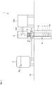
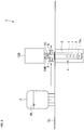
- FIGs. 1 and 2 are respectively schematic configuration diagrams of a liquid pressurizing apparatus according to an embodiment.
- a liquid pressurizing apparatus 1 includes a tank 2 for storing liquid to be pressurized, a vertical pump 4 for pressurizing the liquid supplied from the tank 2, a motor 12A or 12B for driving the vertical pump 4.
- the tank 2 is installed on a device installation surface GL and a fluid level FL in the tank 2 is positioned above the device installation surface GL.
- At least a part of the vertical pump 4 is housed in a recessed part 3 formed by digging down from the device installation surface GL.
- a lower part of the vertical pump 4 is housed in the recessed part 3.
- the vertical pump 4 includes a suction port 5 connected to the tank 2, multi-stage impellers 7 arranged in a vertical direction, a discharge port 6 for discharging the liquid passing through the multi-stage impellers 7.
- An impeller 7 positioned at the lowest position among the multi-stage impellers 7 is a first stage impeller 7A.
- the first stage impeller 7A positions below the device installation surface GL to which the tank 2 is installed.
- the vertical pump 4 has a rotary shaft 10 extending along the vertical direction.
- the rotary shaft 10 is connected to an output shaft 13A of the motor 12A or an output shaft 13B of the motor 12B, thus the multi-stage impellers 7 is configured to rotate with the rotary shaft 10 by being driven by the motor 12A or the motor 12B.
- the vertical pump 4 is configured such that the liquid from the tank 2 is supplied through the suction port 5.
- the liquid supplied from the suction port 5 flows into the first stage impeller 7A, passes through the first stage impeller 7A and flows sequentially to downstream side impellers 7.
- the liquid is pressurized by receiving rotational energy of the impellers 7 when passing through the multi-stage impellers 7.
- the high-pressure liquid passing through the final stage impeller 7 provided on the most downstream side of the multi-stage impellers 7 is discharged from the vertical pump 4 through the discharge port 6.
- the use of the multi-stage vertical pump 4 described above can reduce the installation space of the apparatus as compared with the use of a horizontal type multi-stage pump in which the plurality of stages of the impellers are arranged in the horizontal direction. Further while securing high discharge pressure by increasing the number of stages of the impellers 7, it is possible to reduce the number of revolutions of the pump. Thus, it is possible to suppress cavitation in the first stage impeller 7A by reducing the number of revolutions of the pump.
- the vertical pump 4 is arranged so that the first stage impeller 7A is positioned below the device installation surface GL, thus it is possible to suppress cavitation in the first stage impeller 7A while reducing the height of the installation position of the tank 2 and sufficiently secure a head difference between the tank 2 and the vertical pump 4.
- the output shaft 13A of the motor 12A (first motor) for driving the vertical pump 4 extends along the horizontal direction.
- a bevel gear 8 is provided over the vertical pump 4 for transmitting power between the output shaft 13A of the motor 12A and the rotary shaft 10 of the vertical pump 4.
- the motor 12A is positioned on the side of vertical pump 4 without overlapping with the vertical pump 4 in the plan view.
- the vertical pump 4 and the motor 12A don't overlap each other in the plain view. Maintenance for the vertical pump 4 is performed easily by removing only the bevel gear 8 while the motor 12A is attached.
- the output shaft 13B of the motor 12B (second motor) for driving the vertical pump 4 extends along the vertical direction and the output shaft 13B directly connects to the rotary shaft 10 of the vertical pump 4.
- the vertical pump 4 is capable of reducing the number of revolutions of the pump, while securing high discharge pressure by increasing the number of stages of the impellers. It is unnecessary to provide a speed increasing unit between the output shaft 13B of the motor 12B and the rotary shaft 10 of the vertical pump 4. Further, both of the output shaft 13B of the motor 12B and the rotary shaft 10 of the vertical pump 4 extend along the vertical direction. It is unnecessary to provide a mechanism (e.g. Bevel gear) for converting power transmission direction between the output shaft 13B and the rotary shaft 10. Then, in the embodiment depicted in FIG. 2 , it is possible to configure such that the output shaft 13B and the rotary shaft 10 are directly connected. Accordingly, a lubricating oil unit for circulating lubricating oil supplied to such a speed increasing unit becomes unnecessary, which enables to further reduce the size and facility cost of the liquid pressurizing apparatus 1.
- a speed increasing unit between the output shaft 13B of the motor 12B and the rotary shaft 10 of the vertical pump 4.
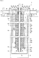
- FIG. 3 is a schematic configuration diagram of a vertical pump 4 according to an embodiment.
- An arrow in FIG. 3 represents a direction of a flow of liquid pressurized by the vertical pump 4.
- the vertical pump 4 includes the multi-stage impellers 7 described above, and a casing including an outer casing 18, an intermediate casing 20 and a casing cover 28.
- the multi-stage impellers 7 is accommodated in the casing.
- the intermediate casing 20 is provided inside the outer casing 18 so as to cover the multi-stage impellers 7.
- the casing cover 28 is attached to the outer casing 18 so as to seal an upper end opening of the outer casing 18.
- the rotary shaft 10 rotating with the multi-stage impellers 7 is rotatably supported by the intermediate casing 20 by way of bearings 72, 74.
- the outer casing 18 includes a flange part 18a provided on an upper end part so as to protrude outward in a radial direction of the rotary shaft 10 (hereinafter, referred to as simply "radial direction"), and is fixed to the device installation surface GL by a plurality of bolts 29 passing through bolt holes provided in the flange part 18a.
- a portion of the outer casing 18 below the flange part 18a is housed in a recessed part 3 formed by digging down from the device installation surface GL.
- the casing cover 28 is fixed to the outer casing 18 by bolts 29 arranged in a circumferential direction of the rotary shaft 10.
- a first internal flow passage 30 communicating with the suction port 5 and a second internal flow passage 32 communicating with the discharge port 6 are formed in the casing cover 28.
- the second internal flow passage 32 includes an annular flow passage 34 communicating with an outlet of the final stage impeller 7B closest to the casing cover 28 among the multi-stage impellers 7.
- the liquid flowing toward the first stage impeller 7A through the flow passage 40 is led to a suction bell 26b (described below) located at the lowest part of the intermediate casing 20, and the liquid flows into the first stage impeller 7A.
- liquid passing through the multi-stage impeller 7 and flowing out from an outlet port of the final stage impeller 7B is discharged from the discharge port 6 to an outside of the vertical pump 4 through the second internal flow passage 32 including the annular flow passage 34.
- the suction port 5 may be provided at a suction nozzle 36 attached at the casing cover 28, and the suction port 5 and the first internal flow passage 30 may be communicated by way of a through hole penetrating through the suction nozzle 36.
- the suction port 6 may be provided at a discharge nozzle 38 attached at the casing cover 28, and the suction port 6 and the second internal flow passage 32 may be communicated by way of a through hole penetrating through the discharge nozzle 38.
- the suction nozzle 36 and the discharge nozzle 38 may be attached to the casing cover 28 by welding.
- the intermediate casing 20 includes a plurality of sections (22A, 22B, 24, 26) stacked in an axial direction of the rotary shaft 10 (hereinafter, referred to as simply "axial direction") and a plurality of tie bolts (42, 44) for fastening the plurality of sections (22A, 22B, 24, 26).
- the plurality of sections constituting of the intermediate casing 20 include a fastening section 24 fixed with one ends of tie bolts (42, 44), a suction bell section 26, a plurality of first sections 22A and second sections 22B which are stacked in the axial direction.
- the fastening section 24 is located on an opposite side of the casing cover 28 across the plurality of first sections 22A in the axial direction. Each one end of the tie bolts 42 is fixed to the fastening section 24 while each other end of the tie bolts 42 is fixed to the casing cover 28.
- the plurality of first sections 22A are arranged between the casing cover 28 and the fastening section 24.
- the suction bell section 26 is located on a side opposite to the casing cover 28 across the multi-stage impellers 7 in the axial direction and has the suction bell 26b for introducing liquid to the first stage impeller 7A of the multi-stage impellers 7.
- Each one end of the tie bolts 43 is fixed to the fastening section 24 while each other end of the tie bolts 43 is fixed to the suction bell section 26.
- the plurality of second sections 22B are arranged between the fastening section 24 and the suction bell section 26.
- the fastening section 24 has a flange part 24a provided so as to protrude outward in the radial direction.
- the flange part 24a is provided with a plurality of bolt holes into which the plurality of tie bolts 42 and the plurality of tie bolts 43 are screwed.
- the suction bell section 26 has a flange part 26a provided so as to protrude outward in the radial direction.
- the flange part 26a is provided with a plurality of bolt holes into which the plurality of tie bolts 43 are screwed.
- Each lower end part of the sections (22A, 22B, 24) and an upper end part of an adjacent section (22A, 22B, 24, 26) to the corresponding one of the sections may have a socket-and-spigot structure 21.
- the socket-and-spigot structure is formed by a convex part provided so as to project downward at an outer peripheral side edge part of each lower end part of the sections (22A, 22B, 24) and a recess part provided on the upper end part of the adjacent section to the corresponding one of the sections so as to correspond to the convex part described above.
- each positioning of the sections (22A, 22B, 24, 26) in the radial direction is facilitated by forming the socket-and-spigot structure between the plurality of adjacent sections,
- the discharge pressure of the vertical pump 4 is 10 MPa or more.
- the liquid pressurizing apparatus 1 uses the vertical pump 4 described above. Even if the discharge pressure of the pump is at a high pressure of 10 MPa or more, it is possible to suppress cavitation in the first stage impeller 7A by locating the multi-stage vertical pump 4 such that the first stage impeller 7A positions below the device installation surface GL. Accordingly, it is not necessary to provide a booster pump between the tank 2 and the vertical pump 4, which achieves reduction in facility cost and space saving.
- the multi-stage impellers 7 include impellers 7 in ten or more stages.
- the vertical pump 4 having the impellers 7 in ten or more stages are used, thus it is possible to ensure a sufficient discharge pressure even if the number of revolutions of the vertical pump 4 is lowered. Thus, it is possible to effectively suppress cavitation in the first stage impeller 7A by reducing the number of revolutions of the vertical pump 4.
- a thrust balancing part 80 for balancing thrust force acting on the rotary shaft 10 is provided in the through hole, which the rotary shaft 10 penetrates, of the casing cover 28.
- the thrust force acting on the rotary shaft 10 is a force in a direction from a high pressure side to a low pressure side of the multi-stage impellers 7 in the axial direction, that is, a force in a direction from the final stage impeller 7B to the first stage impeller 7A.
- the thrust balancing part 80 includes a balance sleeve 82 attached to an outer periphery of the rotary shaft 10 and being configured to rotate with the rotary shaft 10 and a balance bushing 84 provided on the casing cover 28 on an outer peripheral side of the balance sleeve 82.
- an intermediate chamber 54 is formed on the opposite side of the multi-stage impellers 7 across the thrust balancing part 80 in the axial direction between the casing cover 28 and the rotary shaft 10.
- the pressure of the intermediate chamber 54 acts on an upper end surface of the balance sleeve 82.
- the intermediate chamber 54 communicates with an intermediate stage impeller through a balance internal flow passage 56 formed in the casing cover 28 and a balance pipe 58 provided between the intermediate casing 20 and the outer casing 18.
- the "intermediate stage impeller” refers to an arbitrary impeller on the downstream side of the first stage impeller 7A and on the upstream side of the final stage impeller 7B.
- a pressure P M of the intermediate stage impeller is introduced into the intermediate chamber 54 and the pressure P M of the intermediate stage impeller acts on the upper end surface of the balance sleeve 82.
- the pressure P M of the intermediate stage impeller acts on the balance sleeve 82 and it is possible to act a reverse thrust force (force opposite to thrust force described above in axial direction), which is caused by a differential pressure between the pressure (discharge pressure P D (> P M )) of liquid passing through the final stage impeller 7B and the pressure P M of the intermediate stage impeller, on the balance sleeve 82. Accordingly, it is possible to achieve balancing of the thrust force of the vertical pump 4.
- a tandem mechanical seal 44 is provided in the through hole of the rotary shaft 10 of the casing as a shaft sealing device for preventing liquid inside the vertical pump 4 from leaking to the outside.
- the through hole is provided such that the rotary shaft 10 penetrates the casing cover 28 and the seal housing part 46.
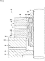
- FIG. 4 is a schematic configuration diagram of the tandem mechanical seal according to an embodiment.
- the tandem mechanical seal 44 depicted in FIG. 4 includes a pair of stationary rings 60A, 60B attached to the seal housing part 46 (casing) and a pair of rotary rings 62A, 62B configured to be rotatable with the rotary shaft 10.
- the rotary rings 62A, 62B are attached to the outer periphery of the rotary shaft 10 and are fixed to an outer peripheral surface of a shaft sleeve 66 configured to rotate with the rotary shaft 10.
- the pair of rotary rings 62A, 62B are configured to slide with respect to the pair of stationary rings 60A, 60B with rotation of the rotary shaft 10, respectively.
- the fluid leakage is suppressed by contacting sliding surfaces of the pair of stationary rings 60A, 60B and the pair of rotary rings 62A, 62B each other.
- a low pressure chamber 48 is provided adjacent to the tandem mechanical seal 44 in the axial direction between the rotary shaft 10 and the casing cover 28 (casing).
- the low pressure chamber 48 communicates with the flow passage 40 formed between the outer casing 18 and the intermediate casing 20 by way of a flushing inlet flow passage 50 formed in the casing cover 28. That is, liquid in low pressure, which flows into the vertical pump 4 from the suction port 5, before being pressurized by the multi-stage impellers 7 is introduced to the low pressure chamber 48 through the flushing inlet flow passage 50.
- a seal chamber 67 to which the outside fluid (buffer fluid) is supplied is provided between the pair of stationary rings 60A, 60B in the axial direction.
- a buffer inlet flow passage 68 and a buffer outlet flow passage 70 are provided in the seal housing part 46.
- the buffer inlet flow passage 68 and the buffer outlet flow passage 70 are connected to an external fluid tank (not shown) provided outside the vertical pump 4. The outside fluid stored in the external fluid tank is introduced into the seal chamber 67 through the buffer inlet flow passage 68, is discharged from the seal chamber 67 via the buffer outlet flow passage 70, and is returned to the external fluid tank.
- a pumping ring 64 is provided on the rotary ring 62B of the pair of rotary rings 62A, 62B, which positions between the pair of stationary rings 60A, 60B, that is, one rotary ring provided in the seal chamber 67.
- the tandem mechanical seal 44 is configured so that the outside fluid is sent from the seal chamber 67 to the external fluid tank through the buffer outlet flow passage 70 by the pumping ring 64.
- tandem mechanical seal 44 described above is used as a shaft sealing device, which is capable of sealing process fluid in the vertical pump by using the external fluid (buffer fluid) being in lower pressure than the double mechanical seal.
- the pumping ring 64 can circulate the buffer fluid by using the tandem mechanical seal 44 described above, then an auxiliary machine for circulating the buffer fluid is not necessary. Accordingly, it is possible to simplify the auxiliary machine for pressurizing and circulating the barrier fluid supplied to the shaft seal device and simplify the configuration of the liquid pressurizing apparatus (see FIGs. 1 and 2 ) as compared with a case where the double mechanical seal is adopted.
- a urea synthesis plant (not shown) may include the liquid pressurizing apparatus 1 including the vertical pump 4 described above.
- the urea synthesis plant includes an ammonia pump for pressurizing a raw material ammonia, a carbamate pump for pressurizing a carbamate and a reactor to which the ammonia pressurized by the ammonia pump, the carbamate pressurized by the carbamate pump, and carbon dioxide are supplied.
- At least one of the ammonia pump or the carbamate pump is the vertical pump 4 of the liquid pressurizing apparatus according to some above-described embodiments.
- the liquid to be pressurized is liquid ammonia of a raw material of urea and the liquid ammonia stored in the tank 2 is supplied to the vertical pump 4 through the suction port 5.
- the liquid to be pressurized is an intermediate carbamate (carbamate ammonium) generated by reaction of the ammonia and the carbon dioxide and the liquid carbamate stored in the tank 2 is supplied to the vertical pump 4 through the suction port 5.
- carbamate carbamate ammonium
- the carbamate is generated from ammonia and carbon dioxide under high temperature and high pressure in the reactor to which pressurized ammonia, carbamate and carbon dioxide are supplied. Accordingly, the generated carbamate and a part of the carbamate supplied from the carbamate pump are decomposed into urea and water by a dehydration reaction. Then, the remaining carbamate is sent, for example, to a decomposition tower, heated and decomposed into urea and water by a dehydration reaction. The urea generated by the reactions is separated and recovered as a product. The unreacted remaining carbamate is also separated, recovered, pressurized by the carbamate pump, supplied to the reactor and used in the production of urea.
- the use of the above-described vertical pump 4 as the ammonia pump or the carbamate pump in the urea synthesis plant can reduce the installation space of the apparatus. Further while securing high discharge pressure by increasing the number of stages of the impellers, it is possible to reduce the number of revolutions of the pump. Thus, it is possible to suppress cavitation in the first stage impeller 7A by reducing the number of revolutions of the pump. Further, the vertical pump 4 is arranged so that the first stage impeller 7A is positioned below the device installation surface GL, thus it is possible to suppress cavitation in the first stage impeller 7A while reducing the height of the tank 2 and sufficiently secure a head difference between the tank 2 and the vertical pump 4.
- an expression of relative or absolute arrangement such as “in a direction”, “along a direction”, “parallel”, “orthogonal”, “centered”, “concentric” and “coaxial” shall not be construed as indicating only the arrangement in a strict literal sense, but also includes a state where the arrangement is relatively displaced by a tolerance, or by an angle or a distance whereby it is possible to achieve the same function.
- an expression of an equal state such as “same” “equal” and “uniform” shall not be construed as indicating only the state in which the feature is strictly equal, but also includes a state in which there is a tolerance or a difference that can still achieve the same function.
- an expression of a shape such as a rectangular shape or a cylindrical shape shall not be construed as only the geometrically strict shape, but also includes a shape with unevenness or chamfered corners within the range in which the same effect can be achieved.
Landscapes
- Engineering & Computer Science (AREA)
- Mechanical Engineering (AREA)
- General Engineering & Computer Science (AREA)
- Mining & Mineral Resources (AREA)
- Life Sciences & Earth Sciences (AREA)
- Geology (AREA)
- Physics & Mathematics (AREA)
- Environmental & Geological Engineering (AREA)
- Fluid Mechanics (AREA)
- General Life Sciences & Earth Sciences (AREA)
- Geochemistry & Mineralogy (AREA)
- Structures Of Non-Positive Displacement Pumps (AREA)
Abstract
Description
- The present disclosure relates to a liquid pressurizing apparatus and a urea synthesis plant.
- A multi-stage centrifugal pump having a multi-stage impellers is used as a liquid pressurizing apparatus for generating high pressure liquid.
- For instance,
Patent Document 1 discloses a horizontal high pressure pump having a main shaft extending in a horizontal direction and multi-stage impellers arranged in the main shaft. In the high pressure pump described inPatent Document 1, a booster pump is provided on an upstream side of the multi-stage impellers and the booster pump performs fluid pressurization and increases the suction pressure of the high pressure pump. - Patent Document 1:
JPH1-179191U - Meanwhile, in the liquid pressurizing apparatus generating high pressure liquid, cavitation is likely to occur on an impeller on an inlet side if suction pressure is small.
- Techniques for suppressing such cavitation are to increase suction pressure of the liquid pressurizing apparatus by using the booster pump described in
Patent Document 1, for example, or by increasing water head by providing a tank for liquid supplied to the liquid pressurizing apparatus above the liquid pressurizing apparatus. - However, the techniques cause to increase the number of installation devices for raising suction pressure of the liquid pressurizing apparatus or to increase installation space as the installation position becomes high.
- In view of the above, an object of at least one embodiment of the present invention is to provide a liquid pressurizing apparatus capable of suppressing cavitation while reducing installation space.
-
- (1) A liquid pressurizing apparatus according to at least one embodiment of the present invention comprises:
- a tank provided on a device installation surface for storing liquid so that a fluid level is located above the device installation surface; and
- a vertical pump including a suction port connected to the tank, multi-stage impellers arranged in a vertical direction, and a discharge port for discharging the liquid passing through the multi-stage impellers.
- The multi-stage impellers include a first stage impeller positioned at the lowest part of the multi-stage impellers and being configured such that the liquid from the suction port flows into the first stage impeller.
The first stage impeller is disposed below the device installation surface.
With the above configuration (1), the use of the multi-stage vertical pump can reduce the installation space of the apparatus. Further while securing high discharge pressure by increasing the number of stages of the impellers, it is possible to reduce the number of revolutions of the pump. Thus, it is possible to suppress cavitation in the first stage impeller by reducing the number of revolutions of the pump. Further, the vertical pump is arranged so that the first stage impeller is disposed below the device installation surface, thus it is possible to suppress cavitation in the first stage impeller while reducing the height of the tank and sufficiently secure a head difference between the tank and the vertical pump.
In this way, according to the above configuration (1), since cavitation in the first stage impeller can be suppressed, it is not necessary to provide a booster pump between the tank and the vertical pump, which achieves reduction in facility cost and space saving. - (2) In some embodiments, in the above configuration (1),
The vertical pump includes:- an outer casing at least partially accommodated in a recessed part formed by digging down from the device installation surface;
- an intermediate casing provided inside the outer casing so as to cover the multi-stage impellers; and
- a casing cover attached to the outer casing so as to seal an upper end opening of the outer casing and having a first inner flow channel communicating with the suction port and a second inner flow channel communicating with the discharge port.
A flow passage for the liquid flowing from the suction port and the first inner flow channel toward the first stage impeller positioned at the lowest part is formed between the outer casing and the intermediate casing.
With the above configuration (2), it is possible to introduce the liquid to the first stage impeller positioned sufficiently below the device installation surface while suppressing height of the whole liquid pressurizing apparatus from the device installation surface by accommodating a part of the vertical pump in the recessed part formed at the device installation surface. Accordingly, it is possible to effectively suppress cavitation in the first stage impeller while reducing the height of the tank and sufficiently secure a head difference between the tank and the vertical pump. - (3) In some embodiments, in the above configuration (1) or (2), the configuration further comprises:
- a first motor having an output shaft extending along a horizontal direction and being configured to drive the vertical pump; and
- a bevel gear positioned above the vertical pump and provided between the output shaft of the first motor and a rotary shaft of the vertical pump.
The first motor is positioned on a side of the vertical pump without overlapping with the vertical pump in a plan view.
With the above configuration (3), the vertical pump and the first motor don't overlap each other in the plain view. Maintenance for the vertical pump is performed easily by removing only the bevel gear while the first motor is attached. - (4) In some embodiments, in the above configuration (1) or (2), the configuration further comprises a second motor having an output shaft extending along a vertical direction and being configured to drive the vertical pump.
The output shaft of the second motor is directly connected to the rotary shaft of the vertical pump.
As describe in the above (1), with at least some liquid pressurizing apparatus, it is possible to reduce the number of revolutions of the pump while securing high discharge pressure by increasing the number of stages of the impellers. Thus, with the above configuration (4), the output shaft of the second motor is directly connected to the rotary shaft of the vertical pump, then a speed increasing unit can be omitted. Accordingly, a lubricating oil unit for circulating lubricating oil supplied to the speed increasing unit becomes unnecessary, which enables to further reduce the size and facility cost of the liquid pressurizing apparatus. - (5) In some embodiments, in any one of the above configurations (1) to (4),
The vertical pump includes:- a casing accommodating the multi-stage impellers;
- a rotary shaft configured to rotate with the multi-stage impellers; and
- a tandem mechanical seal provided in a penetration part of the casing for the rotary shaft.
The tandem mechanical seal includes:- a pair of stationary rings provided in the casing;
- a pair of rotary rings configured to be rotatable with the rotary shaft so as to slide with respect to the respective stationary rings; and
- a pumping ring provided on one of the pair of rotary rings that is located between the pair of stationary rings.
With the above configuration (5), the tandem mechanical seal uses a lower pressure buffer fluid than a double mechanical seal which uses a higher pressure barrier fluid than the process fluid, which is capable of sealing the process fluid in the vertical pump. Further, with the above configuration (5), the pumping ring can circulate the buffer fluid, then an auxiliary machine for circulating the buffer fluid is not necessary. Accordingly, it is possible to simplify the auxiliary machine for pressurizing and circulating the barrier fluid supplied to a shaft seal device and simplify the configuration of the liquid pressurizing apparatus as compared with a case where the double mechanical seal is adopted. - (6) In some embodiments, in any one of the above configurations (1) to (5), the discharge pressure of the vertical pump is 10 MPa or more.
Generally, a horizontal pump rotating at a high speed, for example, of 6000 rpm or more is used to obtain a high discharge pressure of 10 MPa or more. However, when using the horizontal pump with a high rotation speed, cavitation in the first stage impeller of the horizontal pump may be a problem. It is possible to provide a booster pump, for example, between a tank and the horizontal pump to suppress the cavitation. In this case, it may be a problem that equipment installation space enlarges accompanying installation of the booster pump and facility cost increases.
With the above configuration (6), even if the discharge pressure of the vertical pump is at a high pressure of 10 MPa or more, as described in the above (1), it is possible to suppress cavitation in the first stage impeller by locating the multi-stage impellers such that the first stage impeller positions below the device installation surface. Accordingly, it is not necessary to provide a booster pump between the tank and the vertical pump, which achieves reduction in facility cost and space saving. - (7) In some embodiments, in any one of the above configurations (1) to (6), the multi-stage impellers include impellers in ten or more stages.
With the above configuration (7), the impellers in ten or more stages are used, thus it is possible to ensure a sufficient discharge pressure even if the number of revolutions of the vertical pump is lowered. Thus, it is possible to effectively suppress cavitation in the first stage impeller by reducing the number of revolutions of the vertical pump. - (8) In some embodiments, in any one of the above configurations (1) to (7), The vertical pump is an ammonia pump for pressurizing a raw material ammonia in a urea synthesis plant or a carbamate pump for pressurizing a carbamate that is intermediate in the urea synthesis plant.
The ammonia pump and the carbamate pump in the urea synthesis plant raise the ammonia or the carbamate to a high pressure of, for example, 10 MPa or more and is used to supply the urea to a reactor for generating urea.
In this regard, with the above configuration (8), the use of the multi-stage vertical pump as the ammonia pump or the carbamate pump in the urea synthesis plant can reduce the installation space of the apparatus. Further while securing high discharge pressure by increasing the number of stages of the impellers, it is possible to reduce the number of revolutions of the pump. Thus, it is possible to suppress cavitation in the first stage impeller by reducing the number of revolutions of the pump. Further, the vertical pump is arranged so that the first stage impeller is positioned below the device installation surface, thus it is possible to suppress cavitation in the first stage impeller while reducing the height of the tank and sufficiently secure a head difference between the tank and the vertical pump.
In this way, according to the above configuration (8), since cavitation in the first stage impeller can be suppressed, it is not necessary to provide a booster pump between the tank and the vertical pump, which achieves reduction in facility cost and space saving. - (9) A urea synthesis plant according to at least one embodiment of the present invention comprises:
- an ammonia pump for pressurizing a raw material ammonia;
- a carbamate pump for pressurizing a carbamate that is intermediate; and
- a reactor to which the ammonia pressurized by the ammonia pump, the carbamate pressurized by the carbamate pump, and carbon dioxide are supplied.
- At least one of the ammonia pump or the carbamate pump is the vertical pump of the liquid pressurizing apparatus according to any one of the above (1) to (8).
- With the above configuration (9), the use of the multi-stage vertical pump as the ammonia pump or the carbamate pump in the urea synthesis plant can reduce the installation space of the apparatus. Further while securing high discharge pressure by increasing the number of stages of the impellers, it is possible to reduce the number of revolutions of the pump. Thus, it is possible to suppress cavitation in the first stage impeller by reducing the number of revolutions of the pump. Further, the vertical pump is arranged so that the first stage impeller is positioned below the device installation surface, thus it is possible to suppress cavitation in the first stage impeller while reducing the height of the tank and sufficiently secure a head difference between the tank and the vertical pump.
- In this way, according to the above configuration (9), since cavitation in the first stage impeller can be suppressed, it is not necessary to provide a booster pump between the tank and the vertical pump, which achieves reduction in facility cost and space saving.
- According to at least one embodiment of the present invention, the liquid pressurizing apparatus capable of suppressing cavitation while reducing the installation space is provided.
-
-
FIG. 1 is a schematic configuration diagram of a liquid pressurizing apparatus according to an embodiment. -
FIG. 2 is a schematic configuration diagram of a liquid pressurizing apparatus according to an embodiment. -
FIG. 3 is a schematic configuration diagram of a vertical pump according to an embodiment. -
FIG. 4 is a schematic configuration diagram of a tandem mechanical seal according to an embodiment. - Embodiments of the present invention will now be described in detail with reference to the accompanying drawings. It is intended, however, that unless particularly identified, dimensions, materials, shapes, relative positions and the like of components described in the embodiments shall be interpreted as illustrative only and not intended to limit the scope of the present invention.
-
FIGs. 1 and2 are respectively schematic configuration diagrams of a liquid pressurizing apparatus according to an embodiment. As shown inFIGs. 1 and2 , aliquid pressurizing apparatus 1 according to some embodiments includes atank 2 for storing liquid to be pressurized, avertical pump 4 for pressurizing the liquid supplied from thetank 2, amotor vertical pump 4. - The
tank 2 is installed on a device installation surface GL and a fluid level FL in thetank 2 is positioned above the device installation surface GL. - As shown in
FIGs.1 and2 , at least a part of thevertical pump 4 is housed in a recessedpart 3 formed by digging down from the device installation surface GL. In an illustrative embodiment depicted inFIGs. 1 and2 , a lower part of thevertical pump 4 is housed in the recessedpart 3. - The
vertical pump 4 includes asuction port 5 connected to thetank 2,multi-stage impellers 7 arranged in a vertical direction, adischarge port 6 for discharging the liquid passing through themulti-stage impellers 7. Animpeller 7 positioned at the lowest position among themulti-stage impellers 7 is afirst stage impeller 7A. Thefirst stage impeller 7A positions below the device installation surface GL to which thetank 2 is installed. - Further, the
vertical pump 4 has arotary shaft 10 extending along the vertical direction. Therotary shaft 10 is connected to anoutput shaft 13A of themotor 12A or anoutput shaft 13B of themotor 12B, thus themulti-stage impellers 7 is configured to rotate with therotary shaft 10 by being driven by themotor 12A or themotor 12B. - The
vertical pump 4 is configured such that the liquid from thetank 2 is supplied through thesuction port 5. The liquid supplied from thesuction port 5 flows into thefirst stage impeller 7A, passes through thefirst stage impeller 7A and flows sequentially todownstream side impellers 7. The liquid is pressurized by receiving rotational energy of theimpellers 7 when passing through themulti-stage impellers 7. The high-pressure liquid passing through thefinal stage impeller 7 provided on the most downstream side of themulti-stage impellers 7 is discharged from thevertical pump 4 through thedischarge port 6. - In the
liquid pressurizing apparatus 1, the use of the multi-stagevertical pump 4 described above can reduce the installation space of the apparatus as compared with the use of a horizontal type multi-stage pump in which the plurality of stages of the impellers are arranged in the horizontal direction. Further while securing high discharge pressure by increasing the number of stages of theimpellers 7, it is possible to reduce the number of revolutions of the pump. Thus, it is possible to suppress cavitation in thefirst stage impeller 7A by reducing the number of revolutions of the pump. Further, thevertical pump 4 is arranged so that thefirst stage impeller 7A is positioned below the device installation surface GL, thus it is possible to suppress cavitation in thefirst stage impeller 7A while reducing the height of the installation position of thetank 2 and sufficiently secure a head difference between thetank 2 and thevertical pump 4. - Thus, since cavitation in the
first stage impeller 7A can be suppressed by using thevertical pump 4, it is not necessary to provide a booster pump between thetank 2 and the pump (vertical pump 4) or it is not necessary to set thetank 2 at high installation position. Accordingly, it is possible to achieve reduction in facility cost and space saving in theliquid pressurizing apparatus 1. - In an illustrative embodiment depicted in
FIG. 1 , theoutput shaft 13A of themotor 12A (first motor) for driving thevertical pump 4 extends along the horizontal direction. Abevel gear 8 is provided over thevertical pump 4 for transmitting power between theoutput shaft 13A of themotor 12A and therotary shaft 10 of thevertical pump 4. Further, themotor 12A is positioned on the side ofvertical pump 4 without overlapping with thevertical pump 4 in the plan view. - In this way, the
vertical pump 4 and themotor 12A don't overlap each other in the plain view. Maintenance for thevertical pump 4 is performed easily by removing only thebevel gear 8 while themotor 12A is attached. - In the illustrative embodiment shown in
FIG. 2 , theoutput shaft 13B of themotor 12B (second motor) for driving thevertical pump 4 extends along the vertical direction and theoutput shaft 13B directly connects to therotary shaft 10 of thevertical pump 4. - As described the above, the
vertical pump 4 is capable of reducing the number of revolutions of the pump, while securing high discharge pressure by increasing the number of stages of the impellers. It is unnecessary to provide a speed increasing unit between theoutput shaft 13B of themotor 12B and therotary shaft 10 of thevertical pump 4. Further, both of theoutput shaft 13B of themotor 12B and therotary shaft 10 of thevertical pump 4 extend along the vertical direction. It is unnecessary to provide a mechanism (e.g. Bevel gear) for converting power transmission direction between theoutput shaft 13B and therotary shaft 10. Then, in the embodiment depicted inFIG. 2 , it is possible to configure such that theoutput shaft 13B and therotary shaft 10 are directly connected. Accordingly, a lubricating oil unit for circulating lubricating oil supplied to such a speed increasing unit becomes unnecessary, which enables to further reduce the size and facility cost of theliquid pressurizing apparatus 1. -
FIG. 3 is a schematic configuration diagram of avertical pump 4 according to an embodiment. An arrow inFIG. 3 represents a direction of a flow of liquid pressurized by thevertical pump 4. - As shown in
FIG. 3 , thevertical pump 4 includes themulti-stage impellers 7 described above, and a casing including anouter casing 18, anintermediate casing 20 and acasing cover 28. Themulti-stage impellers 7 is accommodated in the casing. Theintermediate casing 20 is provided inside theouter casing 18 so as to cover themulti-stage impellers 7. Thecasing cover 28 is attached to theouter casing 18 so as to seal an upper end opening of theouter casing 18. Further, therotary shaft 10 rotating with themulti-stage impellers 7 is rotatably supported by theintermediate casing 20 by way ofbearings - The
outer casing 18 includes aflange part 18a provided on an upper end part so as to protrude outward in a radial direction of the rotary shaft 10 (hereinafter, referred to as simply "radial direction"), and is fixed to the device installation surface GL by a plurality ofbolts 29 passing through bolt holes provided in theflange part 18a. A portion of theouter casing 18 below theflange part 18a is housed in a recessedpart 3 formed by digging down from the device installation surface GL. - The
casing cover 28 is fixed to theouter casing 18 bybolts 29 arranged in a circumferential direction of therotary shaft 10. A first internal flow passage 30 communicating with thesuction port 5 and a secondinternal flow passage 32 communicating with thedischarge port 6 are formed in thecasing cover 28. Further, the secondinternal flow passage 32 includes anannular flow passage 34 communicating with an outlet of thefinal stage impeller 7B closest to thecasing cover 28 among themulti-stage impellers 7. - A
flow passage 40 for liquid flowing from the first internal flow passage 30 formed in thesuction port 5 and thecasing cover 28 toward thefirst stage impeller 7A positioned at the lowest part of themulti-stage impellers 7, is formed between theouter casing 18 and theintermediate casing 20. - The liquid flowing toward the
first stage impeller 7A through theflow passage 40 is led to asuction bell 26b (described below) located at the lowest part of theintermediate casing 20, and the liquid flows into thefirst stage impeller 7A. - Further, the liquid passing through the
multi-stage impeller 7 and flowing out from an outlet port of thefinal stage impeller 7B is discharged from thedischarge port 6 to an outside of thevertical pump 4 through the secondinternal flow passage 32 including theannular flow passage 34. - As shown in
FIG. 3 , thesuction port 5 may be provided at asuction nozzle 36 attached at thecasing cover 28, and thesuction port 5 and the first internal flow passage 30 may be communicated by way of a through hole penetrating through thesuction nozzle 36. Further, as shown inFIG. 3 , thesuction port 6 may be provided at adischarge nozzle 38 attached at thecasing cover 28, and thesuction port 6 and the secondinternal flow passage 32 may be communicated by way of a through hole penetrating through thedischarge nozzle 38. Thesuction nozzle 36 and thedischarge nozzle 38 may be attached to thecasing cover 28 by welding. - The
intermediate casing 20 includes a plurality of sections (22A, 22B, 24, 26) stacked in an axial direction of the rotary shaft 10 (hereinafter, referred to as simply "axial direction") and a plurality of tie bolts (42, 44) for fastening the plurality of sections (22A, 22B, 24, 26). - In the illustrative embodiment depicted in
FIG. 3 , the plurality of sections constituting of theintermediate casing 20 include afastening section 24 fixed with one ends of tie bolts (42, 44), asuction bell section 26, a plurality offirst sections 22A andsecond sections 22B which are stacked in the axial direction. - The
fastening section 24 is located on an opposite side of thecasing cover 28 across the plurality offirst sections 22A in the axial direction. Each one end of thetie bolts 42 is fixed to thefastening section 24 while each other end of thetie bolts 42 is fixed to thecasing cover 28. The plurality offirst sections 22A are arranged between thecasing cover 28 and thefastening section 24. - The
suction bell section 26 is located on a side opposite to thecasing cover 28 across themulti-stage impellers 7 in the axial direction and has thesuction bell 26b for introducing liquid to thefirst stage impeller 7A of themulti-stage impellers 7. Each one end of thetie bolts 43 is fixed to thefastening section 24 while each other end of thetie bolts 43 is fixed to thesuction bell section 26. The plurality ofsecond sections 22B are arranged between thefastening section 24 and thesuction bell section 26. - The
fastening section 24 has aflange part 24a provided so as to protrude outward in the radial direction. Theflange part 24a is provided with a plurality of bolt holes into which the plurality oftie bolts 42 and the plurality oftie bolts 43 are screwed. - Further, the
suction bell section 26 has aflange part 26a provided so as to protrude outward in the radial direction. Theflange part 26a is provided with a plurality of bolt holes into which the plurality oftie bolts 43 are screwed. - Each lower end part of the sections (22A, 22B, 24) and an upper end part of an adjacent section (22A, 22B, 24, 26) to the corresponding one of the sections may have a socket-and-
spigot structure 21. - In an illustrative embodiment shown in
FIG. 3 , the socket-and-spigot structure is formed by a convex part provided so as to project downward at an outer peripheral side edge part of each lower end part of the sections (22A, 22B, 24) and a recess part provided on the upper end part of the adjacent section to the corresponding one of the sections so as to correspond to the convex part described above. - Thus, each positioning of the sections (22A, 22B, 24, 26) in the radial direction is facilitated by forming the socket-and-spigot structure between the plurality of adjacent sections,
- In some embodiments, the discharge pressure of the
vertical pump 4 is 10 MPa or more. - The liquid pressurizing apparatus 1 (see
FIGs. 1 and2 ) uses thevertical pump 4 described above. Even if the discharge pressure of the pump is at a high pressure of 10 MPa or more, it is possible to suppress cavitation in thefirst stage impeller 7A by locating the multi-stagevertical pump 4 such that thefirst stage impeller 7A positions below the device installation surface GL. Accordingly, it is not necessary to provide a booster pump between thetank 2 and thevertical pump 4, which achieves reduction in facility cost and space saving. - In some embodiments, the
multi-stage impellers 7 includeimpellers 7 in ten or more stages. - In the liquid pressurizing apparatus 1 (see
FIGs. 1 and2 ), thevertical pump 4 having theimpellers 7 in ten or more stages are used, thus it is possible to ensure a sufficient discharge pressure even if the number of revolutions of thevertical pump 4 is lowered. Thus, it is possible to effectively suppress cavitation in thefirst stage impeller 7A by reducing the number of revolutions of thevertical pump 4. - In some embodiments, as shown in
FIG. 3 , a thrust balancing part 80 for balancing thrust force acting on therotary shaft 10 is provided in the through hole, which therotary shaft 10 penetrates, of thecasing cover 28. The thrust force acting on therotary shaft 10 is a force in a direction from a high pressure side to a low pressure side of themulti-stage impellers 7 in the axial direction, that is, a force in a direction from thefinal stage impeller 7B to thefirst stage impeller 7A. - The thrust balancing part 80 includes a
balance sleeve 82 attached to an outer periphery of therotary shaft 10 and being configured to rotate with therotary shaft 10 and a balance bushing 84 provided on thecasing cover 28 on an outer peripheral side of thebalance sleeve 82. - Further, an
intermediate chamber 54 is formed on the opposite side of themulti-stage impellers 7 across the thrust balancing part 80 in the axial direction between thecasing cover 28 and therotary shaft 10. The pressure of theintermediate chamber 54 acts on an upper end surface of thebalance sleeve 82. - The
intermediate chamber 54 communicates with an intermediate stage impeller through a balance internal flow passage 56 formed in thecasing cover 28 and abalance pipe 58 provided between theintermediate casing 20 and theouter casing 18. In the present specification, the "intermediate stage impeller" refers to an arbitrary impeller on the downstream side of thefirst stage impeller 7A and on the upstream side of thefinal stage impeller 7B. - That is, a pressure PM of the intermediate stage impeller is introduced into the
intermediate chamber 54 and the pressure PM of the intermediate stage impeller acts on the upper end surface of thebalance sleeve 82. - In this way, the pressure PM of the intermediate stage impeller acts on the
balance sleeve 82 and it is possible to act a reverse thrust force (force opposite to thrust force described above in axial direction), which is caused by a differential pressure between the pressure (discharge pressure PD (> PM)) of liquid passing through thefinal stage impeller 7B and the pressure PM of the intermediate stage impeller, on thebalance sleeve 82. Accordingly, it is possible to achieve balancing of the thrust force of thevertical pump 4. - In some embodiments, as shown in
FIG. 3 , a tandemmechanical seal 44 is provided in the through hole of therotary shaft 10 of the casing as a shaft sealing device for preventing liquid inside thevertical pump 4 from leaking to the outside. - In the illustrative embodiment depicted in
FIG. 3 , in the casing having thecasing cover 28 and aseal housing part 46 fixed to thecasing cover 28, the through hole is provided such that therotary shaft 10 penetrates thecasing cover 28 and theseal housing part 46. -
FIG. 4 is a schematic configuration diagram of the tandem mechanical seal according to an embodiment. The tandemmechanical seal 44 depicted inFIG. 4 includes a pair ofstationary rings 60A, 60B attached to the seal housing part 46 (casing) and a pair of rotary rings 62A, 62B configured to be rotatable with therotary shaft 10. The rotary rings 62A, 62B are attached to the outer periphery of therotary shaft 10 and are fixed to an outer peripheral surface of ashaft sleeve 66 configured to rotate with therotary shaft 10. - The stationary ring 60A of the pair of
stationary rings 60A, 60B and therotary ring 62A of the pair of rotary rings 62A, 62B which are arranged on a side closer to themulti-stage impellers 7 in the axial direction, constitute a high-pressure seal 45A, while thestationary ring 60B and therotary ring 62B which are arranged on a side farther from themulti-stage impellers 7 in the axial direction constitute a low-pressure seal 45B. - The pair of rotary rings 62A, 62B are configured to slide with respect to the pair of
stationary rings 60A, 60B with rotation of therotary shaft 10, respectively. The fluid leakage is suppressed by contacting sliding surfaces of the pair ofstationary rings 60A, 60B and the pair of rotary rings 62A, 62B each other. - A
low pressure chamber 48 is provided adjacent to the tandemmechanical seal 44 in the axial direction between therotary shaft 10 and the casing cover 28 (casing). Thelow pressure chamber 48 communicates with theflow passage 40 formed between theouter casing 18 and theintermediate casing 20 by way of a flushinginlet flow passage 50 formed in thecasing cover 28. That is, liquid in low pressure, which flows into thevertical pump 4 from thesuction port 5, before being pressurized by themulti-stage impellers 7 is introduced to thelow pressure chamber 48 through the flushinginlet flow passage 50. - Further, in between the
rotary shaft 10 and a seal housing part 46 (casing), aseal chamber 67 to which the outside fluid (buffer fluid) is supplied is provided between the pair ofstationary rings 60A, 60B in the axial direction. Further, a bufferinlet flow passage 68 and a bufferoutlet flow passage 70 are provided in theseal housing part 46. The bufferinlet flow passage 68 and the bufferoutlet flow passage 70 are connected to an external fluid tank (not shown) provided outside thevertical pump 4. The outside fluid stored in the external fluid tank is introduced into theseal chamber 67 through the bufferinlet flow passage 68, is discharged from theseal chamber 67 via the bufferoutlet flow passage 70, and is returned to the external fluid tank. - A
pumping ring 64 is provided on therotary ring 62B of the pair of rotary rings 62A, 62B, which positions between the pair ofstationary rings 60A, 60B, that is, one rotary ring provided in theseal chamber 67. The tandemmechanical seal 44 is configured so that the outside fluid is sent from theseal chamber 67 to the external fluid tank through the bufferoutlet flow passage 70 by thepumping ring 64. - The tandem
mechanical seal 44 described above is used as a shaft sealing device, which is capable of sealing process fluid in the vertical pump by using the external fluid (buffer fluid) being in lower pressure than the double mechanical seal. - Further, the
pumping ring 64 can circulate the buffer fluid by using the tandemmechanical seal 44 described above, then an auxiliary machine for circulating the buffer fluid is not necessary. Accordingly, it is possible to simplify the auxiliary machine for pressurizing and circulating the barrier fluid supplied to the shaft seal device and simplify the configuration of the liquid pressurizing apparatus (seeFIGs. 1 and2 ) as compared with a case where the double mechanical seal is adopted. - A urea synthesis plant (not shown) according to some embodiments may include the
liquid pressurizing apparatus 1 including thevertical pump 4 described above. - The urea synthesis plant according to some embodiments includes an ammonia pump for pressurizing a raw material ammonia, a carbamate pump for pressurizing a carbamate and a reactor to which the ammonia pressurized by the ammonia pump, the carbamate pressurized by the carbamate pump, and carbon dioxide are supplied. At least one of the ammonia pump or the carbamate pump is the
vertical pump 4 of the liquid pressurizing apparatus according to some above-described embodiments. - For instance, if the ammonia pump is the
vertical pump 4, the liquid to be pressurized is liquid ammonia of a raw material of urea and the liquid ammonia stored in thetank 2 is supplied to thevertical pump 4 through thesuction port 5. - Further, for instance, if the carbamate pump is the
vertical pump 4, the liquid to be pressurized is an intermediate carbamate (carbamate ammonium) generated by reaction of the ammonia and the carbon dioxide and the liquid carbamate stored in thetank 2 is supplied to thevertical pump 4 through thesuction port 5. - In the urea synthesis plant described above, the carbamate is generated from ammonia and carbon dioxide under high temperature and high pressure in the reactor to which pressurized ammonia, carbamate and carbon dioxide are supplied. Accordingly, the generated carbamate and a part of the carbamate supplied from the carbamate pump are decomposed into urea and water by a dehydration reaction. Then, the remaining carbamate is sent, for example, to a decomposition tower, heated and decomposed into urea and water by a dehydration reaction. The urea generated by the reactions is separated and recovered as a product. The unreacted remaining carbamate is also separated, recovered, pressurized by the carbamate pump, supplied to the reactor and used in the production of urea.
- In this way, the use of the above-described
vertical pump 4 as the ammonia pump or the carbamate pump in the urea synthesis plant can reduce the installation space of the apparatus. Further while securing high discharge pressure by increasing the number of stages of the impellers, it is possible to reduce the number of revolutions of the pump. Thus, it is possible to suppress cavitation in thefirst stage impeller 7A by reducing the number of revolutions of the pump. Further, thevertical pump 4 is arranged so that thefirst stage impeller 7A is positioned below the device installation surface GL, thus it is possible to suppress cavitation in thefirst stage impeller 7A while reducing the height of thetank 2 and sufficiently secure a head difference between thetank 2 and thevertical pump 4. - Embodiments of the present invention were described in detail above, but the present invention is not limited thereto, and various amendments and modifications may be implemented.
- Further, in the present specification, an expression of relative or absolute arrangement such as "in a direction", "along a direction", "parallel", "orthogonal", "centered", "concentric" and "coaxial" shall not be construed as indicating only the arrangement in a strict literal sense, but also includes a state where the arrangement is relatively displaced by a tolerance, or by an angle or a distance whereby it is possible to achieve the same function.
- For instance, an expression of an equal state such as "same" "equal" and "uniform" shall not be construed as indicating only the state in which the feature is strictly equal, but also includes a state in which there is a tolerance or a difference that can still achieve the same function.
- Further, for instance, an expression of a shape such as a rectangular shape or a cylindrical shape shall not be construed as only the geometrically strict shape, but also includes a shape with unevenness or chamfered corners within the range in which the same effect can be achieved.
- On the other hand, an expression such as "comprise", "include", "have", "contain" and "constitute" are not intended to be exclusive of other components.
-
- 1
- Liquid pressurizing apparatus
- 2
- Tank
- 3
- Recessed part
- 4
- Vertical pump
- 5
- Suction port
- 6
- Discharge port
- 7
- Impeller
- 7A
- First stage impeller
- 7B
- Final stage impeller
- 8
- Bevel gear
- 10
- Rotary shaft
- 12A,12B
- Motor
- 13A,13B
- Output shaft
- 18
- Outer casing
- 18a
- Flange part
- 20
- Intermediate casing
- 21
- Socket-and-spigot structure
- 22A
- First section
- 22B
- Second section
- 24
- Fastening section
- 24a
- Flange part
- 26
- Suction bell section
- 26a
- Flange part
- 26b
- Suction bell
- 28
- Casing cover
- 29
- Bolt
- 30
- First internal flow passage
- 32
- Second internal flow passage
- 34
- Annular flow passage
- 36
- Suction nozzle
- 38
- Discharge nozzle
- 40
- Flow passage
- 42
- Tie bolt
- 43
- Tie bolt
- 44
- Tandem mechanical seal
- 45A
- High-pressure seal
- 45B
- Low-pressure seal
- 46
- Seal housing part
- 48
- Low pressure chamber
- 50
- Flushing inlet flow passage
- 54
- Intermediate chamber
- 56
- Balance internal flow passage
- 58
- Balance pipe
- 60A,60B
- Stationary ring
- 62A,62B
- Rotary ring
- 64
- Pumping ring
- 66
- Shaft sleeve
- 67
- Seal chamber
- 68
- Buffer inlet flow passage
- 70
- Buffer outlet flow passage
- 72
- Bearing
- 74
- Bearing
- 80
- Thrust balancing part
- 82
- Balance sleeve
- 84
- Balance bushing
- FL
- Fluid level
- GL
- Device installation surface
Claims (9)
- A liquid pressurizing apparatus, comprising:a tank provided on a device installation surface for storing liquid so that a fluid level is located above the device installation surface; anda vertical pump including a suction port connected to the tank, multi-stage impellers arranged in a vertical direction, and a discharge port for discharging the liquid passing through the multi-stage impellers,wherein the multi-stage impellers include a first stage impeller positioned at the lowest part of the multi-stage impellers and being configured such that the liquid from the suction port flows into the first stage impeller, andwherein the first stage impeller is disposed below the device installation surface.
- The liquid pressurizing apparatus according to claim 1,
wherein the vertical pump includes:an outer casing at least partially accommodated in a recessed part formed by digging down from the device installation surface;an intermediate casing provided inside the outer casing so as to cover the multi-stage impellers; anda casing cover attached to the outer casing so as to seal an upper end opening of the outer casing, the casing cover having a first inner flow channel communicating with the suction port and a second inner flow channel communicating with the discharge port,wherein a flow passage for the liquid flowing from the suction port and the first inner flow channel toward the first stage impeller positioned at the lowest part is formed between the outer casing and the intermediate casing. - The liquid pressurizing apparatus according to claim 1 or 2, further comprising:a first motor having an output shaft extending along a horizontal direction and being configured to drive the vertical pump; anda bevel gear positioned above the vertical pump and provided between the output shaft of the first motor and a rotary shaft of the vertical pump,wherein the first motor is positioned on a side of the vertical pump without overlapping with the vertical pump in a plan view.
- The liquid pressurizing apparatus according to claim 1 or 2, further comprising a second motor having an output shaft extending along a vertical direction and being configured to drive the vertical pump,
wherein the output shaft of the second motor is directly connected to the rotary shaft of the vertical pump. - The liquid pressurizing apparatus according to any one of claims 1 to 4, wherein the vertical pump includes:a casing accommodating the multi-stage impellers;a rotary shaft configured to rotate with the multi-stage impellers; anda tandem mechanical seal provided in a penetration part of the casing for the rotary shaft, andwherein the tandem mechanical seal includes:a pair of stationary rings provided in the casing;a pair of rotary rings configured to be rotatable with the rotary shaft so as to slide with respect to the respective stationary rings; anda pumping ring provided on one of the pair of rotary rings that is located between the pair of stationary rings.
- The liquid pressurizing apparatus according to any one of claims 1 to 5,
wherein the discharge pressure of the vertical pump is 10 MPa or more. - The liquid pressurizing apparatus according to any one of claims 1 to 6,
wherein the multi-stage impellers include impellers in ten or more stages. - The liquid pressurizing apparatus according to any one of claims 1 to 7,
wherein the vertical pump is an ammonia pump for pressurizing a raw material ammonia in a urea synthesis plant or a carbamate pump for pressurizing a carbamate that is intermediate in the urea synthesis plant. - A urea synthesis plant, comprising:an ammonia pump for pressurizing a raw material ammonia;a carbamate pump for pressurizing a carbamate that is intermediate; anda reactor to which the ammonia pressurized by the ammonia pump, the carbamate pressurized by the carbamate pump, and carbon dioxide are supplied,wherein at least one of the ammonia pump or the carbamate pump is the vertical pump of the liquid pressurizing apparatus according to any one of claims 1 to 8.
Applications Claiming Priority (2)
| Application Number | Priority Date | Filing Date | Title |
|---|---|---|---|
| JP2017002210A JP6940952B2 (en) | 2017-01-10 | 2017-01-10 | Liquid booster and urea synthesis plant |
| PCT/JP2017/039634 WO2018131268A1 (en) | 2017-01-10 | 2017-11-01 | Liquid pressure boosting device and urea synthesis plant |
Publications (2)
| Publication Number | Publication Date |
|---|---|
| EP3486492A1 true EP3486492A1 (en) | 2019-05-22 |
| EP3486492A4 EP3486492A4 (en) | 2019-07-10 |
Family
ID=62839355
Family Applications (1)
| Application Number | Title | Priority Date | Filing Date |
|---|---|---|---|
| EP17891724.1A Withdrawn EP3486492A4 (en) | 2017-01-10 | 2017-11-01 | LIQUID PRESSURE AMPLIFICATION DEVICE AND UREA SYNTHESIS INSTALLATION |
Country Status (5)
| Country | Link |
|---|---|
| US (1) | US11542947B2 (en) |
| EP (1) | EP3486492A4 (en) |
| JP (1) | JP6940952B2 (en) |
| CN (1) | CN109563837A (en) |
| WO (1) | WO2018131268A1 (en) |
Families Citing this family (2)
| Publication number | Priority date | Publication date | Assignee | Title |
|---|---|---|---|---|
| AU2023293019A1 (en) * | 2022-06-17 | 2025-01-30 | Ebara Corporation | Pump Apparatus |
| CN115788374B (en) * | 2022-11-18 | 2025-01-24 | 中国石油天然气集团有限公司 | A fluid booster for downhole operations |
Family Cites Families (17)
| Publication number | Priority date | Publication date | Assignee | Title |
|---|---|---|---|---|
| DE681087C (en) * | 1936-05-29 | 1939-09-15 | Rudolf Duemmerling | Device on centrifugal pumps to relieve axial thrust |
| JPS59200089A (en) * | 1983-04-27 | 1984-11-13 | Hitachi Ltd | Multi-stage pump |
| JPS6386393U (en) * | 1986-11-25 | 1988-06-06 | ||
| JPS6440713A (en) * | 1987-08-04 | 1989-02-13 | Osaka Gas Co Ltd | Bearing utilizing superconductivity |
| NO163503C (en) * | 1987-10-26 | 1990-06-06 | Kvaerner Eureka As | PUMP UNIT. |
| JPH01179191U (en) | 1988-06-07 | 1989-12-22 | ||
| JPH0710076Y2 (en) * | 1989-03-15 | 1995-03-08 | 三浦工業株式会社 | Seal structure of multi-stage centrifugal pump |
| DE4011475C2 (en) * | 1990-04-09 | 1994-11-17 | Klein Schanzlin & Becker Ag | Pot housing pump |
| JPH0777191A (en) * | 1993-09-08 | 1995-03-20 | Torishima Pump Mfg Co Ltd | Precedent stand-by operating method for pump |
| JPH08277798A (en) * | 1995-04-04 | 1996-10-22 | Tanken Seal C-Kou:Kk | Shaft seal device for ammonia handling equipment provided with rotary shaft |
| EP1923383A1 (en) * | 2006-11-20 | 2008-05-21 | Urea Casale S.A. | Method for the modernization of a urea production plant |
| JP4642788B2 (en) * | 2007-01-22 | 2011-03-02 | 株式会社荏原製作所 | Multistage high pressure pump |
| JP5524293B2 (en) * | 2012-07-24 | 2014-06-18 | 中国電力株式会社 | Volcanic pump |
| CN103570588A (en) * | 2013-08-30 | 2014-02-12 | 北京丰汉工程技术有限公司 | Urea synthesis device and urea synthesis method |
| US9494164B2 (en) * | 2013-10-08 | 2016-11-15 | Henry A. Baski | Turbine-pump system |
| JP6430152B2 (en) * | 2014-06-02 | 2018-11-28 | 株式会社荏原製作所 | Liquid pump and liquid pump system |
| CN205654551U (en) * | 2016-05-25 | 2016-10-19 | 浙江科尔泵业股份有限公司 | Temperature rise control system of high pressure liquefaction hydrocarbon pump |
-
2017
- 2017-01-10 JP JP2017002210A patent/JP6940952B2/en active Active
- 2017-11-01 WO PCT/JP2017/039634 patent/WO2018131268A1/en not_active Ceased
- 2017-11-01 EP EP17891724.1A patent/EP3486492A4/en not_active Withdrawn
- 2017-11-01 CN CN201780048406.9A patent/CN109563837A/en active Pending
- 2017-11-01 US US16/325,815 patent/US11542947B2/en active Active
Also Published As
| Publication number | Publication date |
|---|---|
| EP3486492A4 (en) | 2019-07-10 |
| CN109563837A (en) | 2019-04-02 |
| WO2018131268A1 (en) | 2018-07-19 |
| US20210363996A1 (en) | 2021-11-25 |
| US11542947B2 (en) | 2023-01-03 |
| JP2018112106A (en) | 2018-07-19 |
| JP6940952B2 (en) | 2021-09-29 |
Similar Documents
| Publication | Publication Date | Title |
|---|---|---|
| US10704559B2 (en) | Vertical pump and urea synthesis plant | |
| CA2934477C (en) | Multistage centrifugal pump with integral abrasion-resistant axial thrust bearings | |
| US8419398B2 (en) | Method and apparatus for managing fluid flow within a screw pump system | |
| US12006946B2 (en) | Process fluid lubricated pump and pumping system | |
| US20200340479A1 (en) | Centrifugal pump | |
| US11542947B2 (en) | Liquid pressurizing apparatus and urea synthesis plant | |
| US20100278672A1 (en) | Method and apparatus for lubricating a screw pump system | |
| AU2020223675B2 (en) | Pump for conveying a fluid | |
| JP2014074359A (en) | Multistage pump | |
| JP6920819B2 (en) | Vertical pump, its casing cover, urea synthesis plant, and casing cover manufacturing method for vertical pumps | |
| US20170211581A1 (en) | Centrifugal pump | |
| CN203717362U (en) | High-speed hydrogenation feeding pump | |
| US20100329900A1 (en) | Pump for Pumping Fluids | |
| US12546330B2 (en) | Bearing assemblies, apparatuses, devices, systems, and methods including bearings | |
| KR101424038B1 (en) | Recovery system for cooling water reakage of coolant pump | |
| JP6968539B2 (en) | Vertical pump and urea synthesis plant | |
| US8403625B2 (en) | Pitot tube pump | |
| KR101409880B1 (en) | Reactor coolant pump with back blades | |
| JP7012435B2 (en) | Vertical pump and urea synthesis plant | |
| US8882447B2 (en) | Hydraulic machine, an energy conversion installation including such a machine, and the use of a hydrostatic labyrinth-bearing in such a machine | |
| CN219452414U (en) | Coaxial multistage cylinder bag hydraulic flat direct-drive pump | |
| US20100278671A1 (en) | Method and apparatus for reducing particles in a screw pump lubricant | |
| CN109026754A (en) | A pump head device | |
| CN116816456A (en) | Coaxial multistage double-turbine integrated machine | |
| CN121111731A (en) | A high-pressure vertical pump based on a closed-loop high-pressure flow channel |
Legal Events
| Date | Code | Title | Description |
|---|---|---|---|
| STAA | Information on the status of an ep patent application or granted ep patent |
Free format text: STATUS: THE INTERNATIONAL PUBLICATION HAS BEEN MADE |
|
| PUAI | Public reference made under article 153(3) epc to a published international application that has entered the european phase |
Free format text: ORIGINAL CODE: 0009012 |
|
| STAA | Information on the status of an ep patent application or granted ep patent |
Free format text: STATUS: REQUEST FOR EXAMINATION WAS MADE |
|
| 17P | Request for examination filed |
Effective date: 20190218 |
|
| AK | Designated contracting states |
Kind code of ref document: A1 Designated state(s): AL AT BE BG CH CY CZ DE DK EE ES FI FR GB GR HR HU IE IS IT LI LT LU LV MC MK MT NL NO PL PT RO RS SE SI SK SM TR |
|
| AX | Request for extension of the european patent |
Extension state: BA ME |
|
| A4 | Supplementary search report drawn up and despatched |
Effective date: 20190606 |
|
| RIC1 | Information provided on ipc code assigned before grant |
Ipc: F04D 29/12 20060101ALI20190531BHEP Ipc: F04D 7/02 20060101ALI20190531BHEP Ipc: F04D 29/42 20060101ALI20190531BHEP Ipc: F04D 13/16 20060101ALI20190531BHEP Ipc: F04D 1/06 20060101AFI20190531BHEP Ipc: F04D 29/60 20060101ALI20190531BHEP |
|
| STAA | Information on the status of an ep patent application or granted ep patent |
Free format text: STATUS: EXAMINATION IS IN PROGRESS |
|
| 17Q | First examination report despatched |
Effective date: 20200225 |
|
| DAV | Request for validation of the european patent (deleted) | ||
| DAX | Request for extension of the european patent (deleted) | ||
| GRAP | Despatch of communication of intention to grant a patent |
Free format text: ORIGINAL CODE: EPIDOSNIGR1 |
|
| STAA | Information on the status of an ep patent application or granted ep patent |
Free format text: STATUS: GRANT OF PATENT IS INTENDED |
|
| RIC1 | Information provided on ipc code assigned before grant |
Ipc: F04D 29/041 20060101ALI20210823BHEP Ipc: F04D 29/60 20060101ALI20210823BHEP Ipc: F04D 7/02 20060101ALI20210823BHEP Ipc: F04D 29/12 20060101ALI20210823BHEP Ipc: F04D 13/16 20060101ALI20210823BHEP Ipc: F04D 29/42 20060101ALI20210823BHEP Ipc: F04D 1/06 20060101AFI20210823BHEP |
|
| INTG | Intention to grant announced |
Effective date: 20210910 |
|
| STAA | Information on the status of an ep patent application or granted ep patent |
Free format text: STATUS: THE APPLICATION IS DEEMED TO BE WITHDRAWN |
|
| 18D | Application deemed to be withdrawn |
Effective date: 20220121 |