EP3486387B1 - Connecting kit for prefabricated panels and fastening method using such kit - Google Patents
Connecting kit for prefabricated panels and fastening method using such kit Download PDFInfo
- Publication number
- EP3486387B1 EP3486387B1 EP18460024.5A EP18460024A EP3486387B1 EP 3486387 B1 EP3486387 B1 EP 3486387B1 EP 18460024 A EP18460024 A EP 18460024A EP 3486387 B1 EP3486387 B1 EP 3486387B1
- Authority
- EP
- European Patent Office
- Prior art keywords
- socket
- elements
- plug
- precast
- connector
- Prior art date
- Legal status (The legal status is an assumption and is not a legal conclusion. Google has not performed a legal analysis and makes no representation as to the accuracy of the status listed.)
- Active
Links
- 238000000034 method Methods 0.000 title claims description 13
- 230000003014 reinforcing effect Effects 0.000 claims description 25
- 229910052745 lead Inorganic materials 0.000 claims description 18
- 239000002184 metal Substances 0.000 claims description 14
- 229910052751 metal Inorganic materials 0.000 claims description 14
- 238000010276 construction Methods 0.000 claims description 13
- 230000002787 reinforcement Effects 0.000 claims description 9
- 238000009417 prefabrication Methods 0.000 claims description 2
- 229910000831 Steel Inorganic materials 0.000 description 6
- 239000004567 concrete Substances 0.000 description 6
- 239000010959 steel Substances 0.000 description 6
- 230000008878 coupling Effects 0.000 description 3
- 238000010168 coupling process Methods 0.000 description 3
- 238000005859 coupling reaction Methods 0.000 description 3
- 238000005304 joining Methods 0.000 description 3
- 238000004519 manufacturing process Methods 0.000 description 3
- 239000004570 mortar (masonry) Substances 0.000 description 3
- 229920003023 plastic Polymers 0.000 description 3
- 239000004033 plastic Substances 0.000 description 3
- 230000007423 decrease Effects 0.000 description 2
- 238000010586 diagram Methods 0.000 description 2
- 239000007788 liquid Substances 0.000 description 2
- 239000000463 material Substances 0.000 description 2
- 230000001681 protective effect Effects 0.000 description 2
- 238000004873 anchoring Methods 0.000 description 1
- 238000005266 casting Methods 0.000 description 1
- 239000000470 constituent Substances 0.000 description 1
- 238000005516 engineering process Methods 0.000 description 1
- 238000009415 formwork Methods 0.000 description 1
- 239000011440 grout Substances 0.000 description 1
- 238000009434 installation Methods 0.000 description 1
- 230000013011 mating Effects 0.000 description 1
- 239000011178 precast concrete Substances 0.000 description 1
- 230000000087 stabilizing effect Effects 0.000 description 1
- 238000003466 welding Methods 0.000 description 1
Images


Classifications
-
- E—FIXED CONSTRUCTIONS
- E04—BUILDING
- E04B—GENERAL BUILDING CONSTRUCTIONS; WALLS, e.g. PARTITIONS; ROOFS; FLOORS; CEILINGS; INSULATION OR OTHER PROTECTION OF BUILDINGS
- E04B1/00—Constructions in general; Structures which are not restricted either to walls, e.g. partitions, or floors or ceilings or roofs
- E04B1/02—Structures consisting primarily of load-supporting, block-shaped, or slab-shaped elements
- E04B1/04—Structures consisting primarily of load-supporting, block-shaped, or slab-shaped elements the elements consisting of concrete, e.g. reinforced concrete, or other stone-like material
- E04B1/043—Connections specially adapted therefor
-
- E—FIXED CONSTRUCTIONS
- E04—BUILDING
- E04B—GENERAL BUILDING CONSTRUCTIONS; WALLS, e.g. PARTITIONS; ROOFS; FLOORS; CEILINGS; INSULATION OR OTHER PROTECTION OF BUILDINGS
- E04B1/00—Constructions in general; Structures which are not restricted either to walls, e.g. partitions, or floors or ceilings or roofs
- E04B1/38—Connections for building structures in general
- E04B1/41—Connecting devices specially adapted for embedding in concrete or masonry
- E04B1/4114—Elements with sockets
-
- E—FIXED CONSTRUCTIONS
- E04—BUILDING
- E04B—GENERAL BUILDING CONSTRUCTIONS; WALLS, e.g. PARTITIONS; ROOFS; FLOORS; CEILINGS; INSULATION OR OTHER PROTECTION OF BUILDINGS
- E04B1/00—Constructions in general; Structures which are not restricted either to walls, e.g. partitions, or floors or ceilings or roofs
- E04B1/38—Connections for building structures in general
- E04B1/48—Dowels, i.e. members adapted to penetrate the surfaces of two parts and to take the shear stresses
- E04B1/483—Shear dowels to be embedded in concrete
-
- E—FIXED CONSTRUCTIONS
- E04—BUILDING
- E04B—GENERAL BUILDING CONSTRUCTIONS; WALLS, e.g. PARTITIONS; ROOFS; FLOORS; CEILINGS; INSULATION OR OTHER PROTECTION OF BUILDINGS
- E04B1/00—Constructions in general; Structures which are not restricted either to walls, e.g. partitions, or floors or ceilings or roofs
- E04B1/38—Connections for building structures in general
- E04B1/61—Connections for building structures in general of slab-shaped building elements with each other
- E04B1/6108—Connections for building structures in general of slab-shaped building elements with each other the frontal surfaces of the slabs connected together
- E04B1/6116—Connections for building structures in general of slab-shaped building elements with each other the frontal surfaces of the slabs connected together by locking means on lateral surfaces
-
- E—FIXED CONSTRUCTIONS
- E04—BUILDING
- E04B—GENERAL BUILDING CONSTRUCTIONS; WALLS, e.g. PARTITIONS; ROOFS; FLOORS; CEILINGS; INSULATION OR OTHER PROTECTION OF BUILDINGS
- E04B1/00—Constructions in general; Structures which are not restricted either to walls, e.g. partitions, or floors or ceilings or roofs
- E04B1/02—Structures consisting primarily of load-supporting, block-shaped, or slab-shaped elements
- E04B1/04—Structures consisting primarily of load-supporting, block-shaped, or slab-shaped elements the elements consisting of concrete, e.g. reinforced concrete, or other stone-like material
- E04B1/043—Connections specially adapted therefor
- E04B1/046—Connections specially adapted therefor using reinforcement loops protruding from the elements
-
- E—FIXED CONSTRUCTIONS
- E04—BUILDING
- E04B—GENERAL BUILDING CONSTRUCTIONS; WALLS, e.g. PARTITIONS; ROOFS; FLOORS; CEILINGS; INSULATION OR OTHER PROTECTION OF BUILDINGS
- E04B1/00—Constructions in general; Structures which are not restricted either to walls, e.g. partitions, or floors or ceilings or roofs
- E04B1/38—Connections for building structures in general
- E04B1/61—Connections for building structures in general of slab-shaped building elements with each other
- E04B2001/6195—Connections for building structures in general of slab-shaped building elements with each other the slabs being connected at an angle, e.g. forming a corner
-
- F—MECHANICAL ENGINEERING; LIGHTING; HEATING; WEAPONS; BLASTING
- F16—ENGINEERING ELEMENTS AND UNITS; GENERAL MEASURES FOR PRODUCING AND MAINTAINING EFFECTIVE FUNCTIONING OF MACHINES OR INSTALLATIONS; THERMAL INSULATION IN GENERAL
- F16B—DEVICES FOR FASTENING OR SECURING CONSTRUCTIONAL ELEMENTS OR MACHINE PARTS TOGETHER, e.g. NAILS, BOLTS, CIRCLIPS, CLAMPS, CLIPS OR WEDGES; JOINTS OR JOINTING
- F16B5/00—Joining sheets or plates, e.g. panels, to one another or to strips or bars parallel to them
- F16B5/0004—Joining sheets, plates or panels in abutting relationship
- F16B5/0056—Joining sheets, plates or panels in abutting relationship by moving the sheets, plates or panels or the interlocking key perpendicular to the main plane
-
- F—MECHANICAL ENGINEERING; LIGHTING; HEATING; WEAPONS; BLASTING
- F16—ENGINEERING ELEMENTS AND UNITS; GENERAL MEASURES FOR PRODUCING AND MAINTAINING EFFECTIVE FUNCTIONING OF MACHINES OR INSTALLATIONS; THERMAL INSULATION IN GENERAL
- F16B—DEVICES FOR FASTENING OR SECURING CONSTRUCTIONAL ELEMENTS OR MACHINE PARTS TOGETHER, e.g. NAILS, BOLTS, CIRCLIPS, CLAMPS, CLIPS OR WEDGES; JOINTS OR JOINTING
- F16B5/00—Joining sheets or plates, e.g. panels, to one another or to strips or bars parallel to them
- F16B5/0004—Joining sheets, plates or panels in abutting relationship
- F16B5/0084—Joining sheets, plates or panels in abutting relationship characterised by particular locking means
- F16B5/0088—Joining sheets, plates or panels in abutting relationship characterised by particular locking means with locking means moving substantially perpendicular to the main plane, e.g. pins, screws
Definitions
- the present invention consists of a connecting kit for fastening prefabricated panels (first and foremost including precast ferroconcrete panels) and the method of fastening prefabricated panels (first and foremost including precast ferroconcrete panels) using the connecting kit, intended for various forms of the construction industry in which prefabricated panels in general (and concrete panels in particular) are used.
- modular construction elements are often fitted with through holes to be filled with a joining medium.
- joining medium may be e.g. liquid concrete or any plug connector, formed by a plug socket and a correspondingly shaped plug.
- the Polish patent description No. PL 179763 teaches a wall-and-ceiling construction kit presented in Fig. Figs. 25, 26, 27, 28 and 29 , consisting of a prefabricated module (1) and connectors.
- the module (1) is formed as two inseparable panels: a wall (A) and a ceiling (B), positioned at an angle of at least 90° to each other, while their height and width are many times greater than their thickness.
- the narrow front surface (a) and the narrow lateral surfaces (b) of the module (1) that may possibly be in contact with similar modules are fitted with ducts (open on the outside) for fitting connectors of the modules (1).
- the prism-shaped connectors exactly reflect the shape of the ducts in the module (1) and can simultaneously fill ducts in two adjacent, contacting modules (1).
- the Polish patent description No. PL 215834 (B1 ) teaches a kit for fastening facade panels, as shown in Fig. 30, 31 , 32 and 33 , consisting of supports and connectors, connected by means of grooved surfaces and fitted with adjustment openings, detachably connected to the building walls and facade panels and/or lintels and door frames.
- a load-bearing support (1) preferably is a cuboid-shaped panel with at least one oval opening (11) with a socket on the smooth-surface side, inside which at least one nut is placed, which - by means of a fastening screw (4) connects a hanger connector (2) with the load-bearing support (1), fitted with at least one oval opening with a socket (22) on the smooth-surface side, whereby the hanger connector (2) has a cutout (23), preferably U-shaped and with oblique lower edges, whereby the cutout (23) has a socket (on the grooved side of the hanger connector (2)) inside which the flange of a hanger sleeve (3) is placed, fitted to a facade element or to the floor.
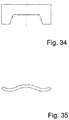
- FIG. 34 and 35 Another example of a connector for fastening construction panels is a fastening element known from the description of the Polish industrial design No. Rp. 16412, as shown in Fib. 34 and 35.
- the connector - in its top view - has the shape of a rectangle with a trapeze cutout the shorter base of which is directed towards the interior of the rectangle.
- the connector resembles a very low, wide and thick letter U.
- the connector In its front view, the connector has the shape of a gently sinusoidal wave with three extremes.
- a fast connection presented in Fig. 36, 37 , 38 and 39 is one of the newest solutions intended for more efficient and faster connection of precast elements, first and foremost fast connection of two vertical walls, corner connections and for connecting columns. It was disclosed in October 2015 in a brochure entitled "TENLOC Element Connector. Fast connection for precast elements ", and then in April 2016 at the BAUMA trade show in Kunststoff .
- the solution is intended for connecting precast wall elements, but can be equally successfully used for connecting walls with posts and for making assembly connections in panel systems, thus enabling instant connection of prefabricated elements.
- the system known commercially as TENLOC is a two-piece latching connector.
- One piece of the connector consists of a latching mechanism, installed in one precast wall element, in a specially profiled housing, inside which a bean-shaped (or croissant-shaped) adapter is positioned, in which a shape-matched connector is placed, through which a U-shaped anchor bar is guided. Furthermore, inside the housing there is a latch with an eccentric connection, serving as a locking lever whose coupling is formed so as to freely pass through a gap in the housing of the other piece of the unit, installed in another precast element and to lock against the anchor element, thus preventing backward movement of that element.
- the coupling, together with reinforcing bars and spacing strips, constitutes concrete reinforcement.
- the entire unit can be connected by means of a pair of connectors. Subsequently, the connectors are filled with non-shrinkable grout to finalize the connection. Already in the precasting plant both parts of the unit are placed in moulds prior to casting. Simultaneously, special markings and spacing strips are placed on the housing of the latching mechanism and on the housing of the anchoring system, to facilitate precise positioning.
- an assembler activates the latching system by means of a hexagonal key (commonly known as Allen key or hex key) through an opening in the mould, thus locking the latch on reinforcing bars on the opposite side. The assembler initiates the actual process of tensioning the bars by further turning the key after locking the latch, thus ensuring a robust connection between the connected walls, free of thermal bridges.
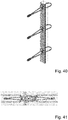
- Fig. 40 and 41 An example of such a connection is presented in Fig. 40 and 41 .
- the best known manufacturers of those connections are PFEIFER and HALFEN.
- Fig. 40 and 41 show the design and method of use of a connection offered by PFEIFER and marketed as VS® PFEIFER System.
- HALFEN offers a very similar system, commercially known as HLB.
- Rope loop connections are common in prefabricated walls (fire walls, curtain walls, load-bearing walls) connected with posts or in walls connected to other walls.
- the sides of wall panels connected with one another are fitted with steel rope loops, protruding to the outside. In order to connect the panels, they need to be positioned so that the loops overlap, following which an essentially vertical reinforcing bar is placed inside the connection and concrete mortar is poured over it.
- connection The working principle of the connection is based on the fact that tensile stresses are taken over by the overlapping steel loops and by the vertical bar placed inside the connection. Compressive stresses are transferred by a highly resistant expansive mortar that tightly fills the resultant dowel "lock". For the time of assembly and concrete curing, a screw joint connection should be provided and removed afterwards. In this solution, some inconvenience is caused by the fact that the system requires formwork and a preliminary screw connection, and a relatively large quantity of concrete is consumed on the assembly site.
- WO 2011/123873 A2 discloses a connecting kit for fastening precast panel elements and a method of connecting precast panel elements using such a connecting kit
- the purpose of the present invention was to develop a connection for prefabricated construction panels ensuring robust and durable connection of wall and ceiling elements with minimum effort.
- the object of the present invention is a connection kit for fastening precast ferroconcrete elements with the features of claim 1, consisting of a three-piece connector, whose one piece is placed in the structure of one precast element, and another piece is placed in the structure of another precast element, fitted with a plug socket and a shape-matched plug connector which unites the two precast elements by fitting into the socket.
- the kit consists of two plug sockets positioned in the two precast elements to be connected and one flat plug connector, whereby each plug socket is fitted with a flat rectangle-shaped element positioned in that part of the housing that is flush with the outer surface of the element being connected and has an internal gap that optionally can have smooth or grooved surface, whose shape matches a half of the plug connector.
- the shape of the plug connector resembles a very low, wide and thick letter U with the profile of a sinusoidally bent plane; the cross-section of the connector has the shape of a wedge tapering towards the end that is hammered into plug sockets.
- the socket has a semicircular cavity.
- the cavity makes it possible to place a reinforcing bar securing the ferroconcrete structure against delaminating.
- the part of the plug socket that is located inside an element to be connected is finished with flat elements whose width is not greater than the width of the gap housing. The purpose of those elements is to protect the socket against being pulled out from the precast element.
- all elements of the plug socket jointly form a module which - once supplemented with a suitable adapter - can be used for connecting corner elements.
- one socket of the connection kit has a different design, supplemented with additional components constituting an adapter.
- the basic additional element is a cuboid chamber.
- One of its walls is formed by a flat element of the plug socket, whereas another, opposite wall is empty and constitutes a rectangular opening in a flat rectangular element connected with the chamber, flush with the side surface of a precast element to be connected.
- the constituent parts of this variety of the plug socket include a set of wedges which constitute the filling of the cuboid chamber of the plug socket after having been hammered inside it.
- the plug connector is preferably made of high-quality steel.
- plug sockets are preferably made of high-quality and high-strength plastics or metal.
- Each plug socket can be additionally reinforced with a rectangular metal plate the surface of which is perpendicular to the surface of the flat element of the socket, and thus in the contact surface of the two sockets, whereby the reinforcing plate and the flat element of the socket have a joint edge.
- each of the plug sockets can be fitted with reinforcements in the form of longitudinal reinforcing bars connected at one end with the metal plates, as well as in the form of crosswise reinforcing bars, whereby the free ends of the bars are bent downward in a hook-like fashion and can be connected with reinforcements of precast elements to be connected.
- the object of the present invention additionally includes the method of connecting precast panels using the kit described above, the method comprising the features of claim 10.
- the essence of the connection method according to the present invention consists in the following:
- connection kit for fastening precast ferroconcrete elements eliminates the need for on-site wet works, i.e. the need to use liquid mortar, as well as welding or joining by means of screw connections.
- the kit ensures highly precise, easy and fast installation of building elements (the calculated time of securing such connection does not exceed 10 minutes of an assembler's work, whereas the time necessary to hammer in the plug connector is as little as a few seconds), which in its turn makes the construction of the entire building less time consuming. It constitutes a durable and elastic connection of adjacent ferroconcrete panels, stabilizing their position and tightening the connected elements.
- the metal connector with the profile of a sinusoidally bent plane, hammered into connecting sockets placed in the structure of adjacent ferroconcrete elements, is a kind of a wall plug. It is fully capable of transmitting loads immediately after deployment. Furthermore, the kit's application minimizes the presence of thermal bridges in external layered walls.
- connection kit is the low cost of such connection, because the simple design and the relatively small amount of material consumed (in the case of connecting sockets - high-quality and high-strength plastics, and in the case of the connector - a high-grade steel) will not only contribute to low manufacturing cost, but will also constitute an advantage from the perspective of the building's investor, by reducing the overall cost of technology and by reducing construction time.
- connection kit according to the invention is intended primarily for connecting ferroconcrete elements, it can also be used for connecting structural elements made of materials other than ferroconcrete.
- connection kit is an all-purpose solution that can be used in various structural arrangements, in corner and parallel connections, equally for wall, floor or ceiling plates, or even foundation beams, or in balcony connections (to connect cantilever plates or to integrate cantilever plates with the ceiling plate).
- a manufacturing plant producing prefabricated elements for the construction industry was asked to manufacture a certain number of ferroconcrete elements of an energy-saving passive fully-detached house. As part of the assignment, the plant was asked to install a system for fast and easy connection of individual panels with one another.
- the connecting kit consisting of a few components, had to be suitable both for in-line connection of two adjacent precast elements and for corner connections, i.e. those when two elements are perpendicular to each other.
- the connecting kit consists of two plug sockets A and B installed in two precast panels Pa and Pb to be connected with each other and one flat plug connector S.
- Each of the plug sockets A and B made of high-quality and high-strength plastics, is fitted with a flat element - 1a in the case of socket A and 1b in the case of socket B.
- both flat elements 1a, 1b are rectangular in shape and are intended to be positioned in that part of the socket that is located in the external plane of the connected element Pa, Pb.
- Each of the plug sockets A and B has an internal smooth-surfaced gap 2a and 2b, shape-matched with a half of the plug connector S, allowing for the plug connector to be hammered in, whereby the width of the internal gap 2 gradually decreases in the direction in which the plug connector S is being hammered in.
- the plug connector S has been made of a high-grade steel and resembles a very low, wide and thick letter U with the profile a sinusoidally bent plane; the cross-section of the connector has the shape of a wedge tapering towards the end that is hammered into the plug sockets A, B.
- the purpose of the plug connector S is to transfer stress to the walls of the gap 2, simultaneously increasing the friction force and preventing the plug connector S from sliding out of the socket A and B.
- the socket Inside the recess formed in part of the plug socket A, B, located inside the connected element Pa, Pb, the socket has a semicircular cavity 3a, 3b to accommodate a reinforcing bar.
- the lower part of the plug socket A, B, located inside the connected element terminates in flat protective elements 4a, 4b, whose width is greater than the width of the housing of the gap 2a, 2b, whose purpose is to prevent the socket from being pulled out from the ferroconcrete structure.
- all elements of the plug socket B jointly constitute a basic module that can serve as a basic component of a plug socket of a different design.
- the connecting kit Z is also formed by two plug sockets A and B, placed inside two precast panel elements Pa, Pb to be connected with each other, and by one flat plug connector S.
- each of the plug sockets A and B is fitted with a flat element - 1a and 1b, respectively, and each of the plug sockets A and B has an internal smooth-surfaced gap 2a and 2b, shape-matched with a half of the plug connector S, allowing for the plug connector to be hammered in, whereby the width of the internal gap 2 gradually decreases in the direction in which the plug connector S is being hammered in.
- each of the plug sockets A, B has additionally been reinforced by the addition of a rectangular metal plate 11a, 11b, whereby the surfaces of both plates are in contact in the place where the plug socket A contacts the plug socket B.
- a gap 12a, 12b In the upper part of each of the plates 11a, 11b there is a gap 12a, 12b, whose width and height match those of the internal gap of the socket 2a, 2b; it is formed so as to match the shape of the connector S hammered into it.
- each of the plug sockets A, B has additionally been fitted with reinforcing elements that help strengthen the structure of the connection, in the form of adequately bent steel reinforcing bars.
- crosswise reinforcing bars 13a, 13b are guided in semicircular cavities 3a, 3b; each bar is bent downward in a hook-like fashion and each supports two longitudinal bars suspended underneath.
- Two bars 14a are hooked under the bar 13a, and two bars 14b are hooked under the bar 13b.
- Each of the bars 14a has one end that is bent downward in a hook-like fashion, whereas its other end is permanently fastened to the upper part of the plate 11a
- each of the bars 14b has one end that is bent downward in a hook-like fashion, whereas its other end is permanently fastened to the upper part of the plate 11b.
- the bars 14a in the case of the plug socket A
- the bars 14b in the case of the plug socket B
- the crosswise clamps 15a, 15b are the bars 13a, 13b.
- the lower part of the plate 11a, 11b of the plug sockets A, B is fastened to one end of two bars 16a and 16b, positioned in parallel to each other.
- the other end of each of those four bars (16a, 16b) is bent downwards in a hook-like fashion.
- the hook-like ends of the bars 14a, 14b, and 16a, 16b are hooked against reinforcing bars Z of the panel elements Pa, Pb.
- the plug socket B constituting the basic module
- the plug socket B adheres with its flat element 1b to a cuboid chamber 5 embedded in the structure of a precast element.
- the flat element 1b has an internal gap 2b, shape-matched with a half of a sinusoidally shaped plug connector S.
- a rectangular flat element 6 is fastened to the wall of the cuboid chamber 5 located on the external plane of the precast element Pb intended to be connected.
- the surface of the flat element 6 has a rectangular opening 7.
- the size of the rectangular opening 7 corresponds to the size of a set of two wedges 8 and 9 which - after having been hammered inside the cuboid chamber 5 formed a cuboid filling 10 of the chamber 5 in the plug socket B 2 . Thanks to the wedges, hammering in the sinusoidally bent plug connector S into the gap 2 was easier, and the resulting filling 10 of the chamber 5 secured the plug connector S against sliding out.
- Ferroconcrete precast elements with pre-installed connecting kits according to the invention were connected by the method according to the invention in a few stages.
- two plug sockets were inserted on both sides of each precast element, depending on its intended use and function (i.e. parallel vs. corner element).
- these were the sockets A or sockets B or sockets B 2 .
- the line running along the contact edges of the connected elements constituted the axis of symmetry of the sockets.
- further assembly operations depend on whether the two precast elements are to be connected in parallel or perpendicular to each other. In the first variant, i.e.
- two plug sockets A and B must be embedded in the structure of precast elements Pa and Pb. Both elements Pa, Pb had to be positioned so that their plug sockets - i.e. the socket A and the socket B - were on the opposite sides in the contact plane of the connected elements. Then, the connector S was hammered into the adequately profiled gap 2, whose shape corresponded to the plug connector S with the profile of a sinusoidally bent plane, formed by the two connected gaps 2a and 2b, positioned in the contact plane of the two elements, created at the moment of connection of the two plug sockets A and B, embedded in the two precast elements Pa, Pb. The entire process of connecting the two elements took an assembler approximately 10 minutes.
- the reinforced kit presented in the second embodiment was manufactured in the prefabrication plant by embedding two plug sockets A and B on both sides in the structure of each precast element Pa, Pb.
- the plug sockets had been reinforced with rectangular plates 11a and 11b.
- the connection between the plug sockets A, B with the structure of the precast elements Pa, Pb was reinforced by means of longitudinal bars 14a, 14b, 16a, 16b clamped with crosswise bars - clamps 13a, 13b, 15a, 15b.
- the said reinforcement was then connected with reinforcement Z of the precast concrete elements Pa, Pb.
- the on-site assembly operations were identical to those performed in the case of the first embodiment of the invention.
- two plug sockets A and B 2 were embedded in the structure of the two precast plate elements Pa, Pb. Both plug sockets were made of metal. Two elements positioned in perpendicular to each other were connected by means of the same, all-purpose plug connector S. The process of hammering-in the connector S was facilitated by the use of the two wedges 8 and 9. The wedges 8 and 9 were hammered in through the opening 7 to the inside of the cuboid chamber 5, thus forming its filling 10. The wedges 8, 9, by fully filling in the cuboid chamber 5 of the plug socket B 2 , ensured full deployment of the plug connector S which completely filled the gap 2a-2b and thus connected the two perpendicular elements Pa, Pb.
Description
- The present invention consists of a connecting kit for fastening prefabricated panels (first and foremost including precast ferroconcrete panels) and the method of fastening prefabricated panels (first and foremost including precast ferroconcrete panels) using the connecting kit, intended for various forms of the construction industry in which prefabricated panels in general (and concrete panels in particular) are used.
- In order to ensure more convenient, joint fixing of modular construction elements, as well as in order to ensure structural tightness, their contact surfaces with other elements are fitted with profiled recesses or protrusions, whose shape matches that of the recess or protrusion in the mating element. Such a solution has been used for years. Furthermore, modular construction elements are often fitted with through holes to be filled with a joining medium. Such joining medium may be e.g. liquid concrete or any plug connector, formed by a plug socket and a correspondingly shaped plug.
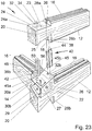
- For instance, the Canadian patent description No.
CA.1242558 (A ), presented inFig. 23 ,24 , teaches a system for quick and durable fastening of a modular house made of wooden logs, where the ends of adjacent logs are adequately profiled and end-joined; furthermore, the logs are connected by means of cylindrically elongated cavities that serve as sockets in which wooden connectors (serving as shafts) are set and which fit perfectly as they are being hammered in. - In its turn, the Polish patent description No.
PL 179763 Figs. 25, 26, 27, 28 and 29 , consisting of a prefabricated module (1) and connectors. The module (1) is formed as two inseparable panels: a wall (A) and a ceiling (B), positioned at an angle of at least 90° to each other, while their height and width are many times greater than their thickness. The narrow front surface (a) and the narrow lateral surfaces (b) of the module (1) that may possibly be in contact with similar modules are fitted with ducts (open on the outside) for fitting connectors of the modules (1). The prism-shaped connectors exactly reflect the shape of the ducts in the module (1) and can simultaneously fill ducts in two adjacent, contacting modules (1). - The Polish patent description No.
PL 215834 (B1 Fig. 30, 31 ,32 and 33 , consisting of supports and connectors, connected by means of grooved surfaces and fitted with adjustment openings, detachably connected to the building walls and facade panels and/or lintels and door frames. In the said kit, a load-bearing support (1) preferably is a cuboid-shaped panel with at least one oval opening (11) with a socket on the smooth-surface side, inside which at least one nut is placed, which - by means of a fastening screw (4) connects a hanger connector (2) with the load-bearing support (1), fitted with at least one oval opening with a socket (22) on the smooth-surface side, whereby the hanger connector (2) has a cutout (23), preferably U-shaped and with oblique lower edges, whereby the cutout (23) has a socket (on the grooved side of the hanger connector (2)) inside which the flange of a hanger sleeve (3) is placed, fitted to a facade element or to the floor. - Another example of a connector for fastening construction panels is a fastening element known from the description of the Polish industrial design No. Rp. 16412, as shown in Fib. 34 and 35. The connector - in its top view - has the shape of a rectangle with a trapeze cutout the shorter base of which is directed towards the interior of the rectangle. The connector resembles a very low, wide and thick letter U. In its front view, the connector has the shape of a gently sinusoidal wave with three extremes.
- A fast connection presented in
Fig. 36, 37 ,38 and 39 , is one of the newest solutions intended for more efficient and faster connection of precast elements, first and foremost fast connection of two vertical walls, corner connections and for connecting columns. It was disclosed in October 2015 in a brochure entitled "TENLOC Element Connector. Fast connection for precast elements", and then in April 2016 at the BAUMA trade show in Munich. The solution is intended for connecting precast wall elements, but can be equally successfully used for connecting walls with posts and for making assembly connections in panel systems, thus enabling instant connection of prefabricated elements. The system known commercially as TENLOC is a two-piece latching connector. One piece of the connector consists of a latching mechanism, installed in one precast wall element, in a specially profiled housing, inside which a bean-shaped (or croissant-shaped) adapter is positioned, in which a shape-matched connector is placed, through which a U-shaped anchor bar is guided. Furthermore, inside the housing there is a latch with an eccentric connection, serving as a locking lever whose coupling is formed so as to freely pass through a gap in the housing of the other piece of the unit, installed in another precast element and to lock against the anchor element, thus preventing backward movement of that element. The coupling, together with reinforcing bars and spacing strips, constitutes concrete reinforcement. By coupling the latching mechanism with the anchor, the connection between the two precast elements is strengthened. - The entire unit can be connected by means of a pair of connectors. Subsequently, the connectors are filled with non-shrinkable grout to finalize the connection.
Already in the precasting plant both parts of the unit are placed in moulds prior to casting. Simultaneously, special markings and spacing strips are placed on the housing of the latching mechanism and on the housing of the anchoring system, to facilitate precise positioning.
On an assembly site, immediately before connecting two precast wall elements, an assembler activates the latching system by means of a hexagonal key (commonly known as Allen key or hex key) through an opening in the mould, thus locking the latch on reinforcing bars on the opposite side. The assembler initiates the actual process of tensioning the bars by further turning the key after locking the latch, thus ensuring a robust connection between the connected walls, free of thermal bridges. - In the recent years, prefabricated construction panels have been increasingly often connected by means of loop connections. An example of such a connection is presented in
Fig. 40 and 41 . The best known manufacturers of those connections are PFEIFER and HALFEN.Fig. 40 and 41 show the design and method of use of a connection offered by PFEIFER and marketed as VS® PFEIFER System.
HALFEN offers a very similar system, commercially known as HLB. Rope loop connections are common in prefabricated walls (fire walls, curtain walls, load-bearing walls) connected with posts or in walls connected to other walls. The sides of wall panels connected with one another are fitted with steel rope loops, protruding to the outside. In order to connect the panels, they need to be positioned so that the loops overlap, following which an essentially vertical reinforcing bar is placed inside the connection and concrete mortar is poured over it. - The working principle of the connection is based on the fact that tensile stresses are taken over by the overlapping steel loops and by the vertical bar placed inside the connection. Compressive stresses are transferred by a highly resistant expansive mortar that tightly fills the resultant dowel "lock".
For the time of assembly and concrete curing, a screw joint connection should be provided and removed afterwards.
In this solution, some inconvenience is caused by the fact that the system requires formwork and a preliminary screw connection, and a relatively large quantity of concrete is consumed on the assembly site. Moreover,WO 2011/123873 A2 discloses a connecting kit for fastening precast panel elements and a method of connecting precast panel elements using such a connecting kit - The purpose of the present invention was to develop a connection for prefabricated construction panels ensuring robust and durable connection of wall and ceiling elements with minimum effort.
- The object of the present invention is a connection kit for fastening precast ferroconcrete elements with the features of
claim 1, consisting of a three-piece connector, whose one piece is placed in the structure of one precast element, and another piece is placed in the structure of another precast element, fitted with a plug socket and a shape-matched plug connector which unites the two precast elements by fitting into the socket. - The essence of the solution according to the present invention is that the kit consists of two plug sockets positioned in the two precast elements to be connected and one flat plug connector, whereby each plug socket is fitted with a flat rectangle-shaped element positioned in that part of the housing that is flush with the outer surface of the element being connected and has an internal gap that optionally can have smooth or grooved surface, whose shape matches a half of the plug connector. The shape of the plug connector resembles a very low, wide and thick letter U with the profile of a sinusoidally bent plane; the cross-section of the connector has the shape of a wedge tapering towards the end that is hammered into plug sockets. Furthermore, inside a recess formed in the lower part of the plug socket, located inside an element to be connected, the socket has a semicircular cavity. The cavity makes it possible to place a reinforcing bar securing the ferroconcrete structure against delaminating.
The part of the plug socket that is located inside an element to be connected is finished with flat elements whose width is not greater than the width of the gap housing. The purpose of those elements is to protect the socket against being pulled out from the precast element.
Importantly, all elements of the plug socket jointly form a module which - once supplemented with a suitable adapter - can be used for connecting corner elements.
To enable the connection of precast elements that are perpendicular to each other, one socket of the connection kit has a different design, supplemented with additional components constituting an adapter. The basic additional element is a cuboid chamber. One of its walls is formed by a flat element of the plug socket, whereas another, opposite wall is empty and constitutes a rectangular opening in a flat rectangular element connected with the chamber, flush with the side surface of a precast element to be connected. The constituent parts of this variety of the plug socket include a set of wedges which constitute the filling of the cuboid chamber of the plug socket after having been hammered inside it.
The plug connector is preferably made of high-quality steel.
Similarly, plug sockets are preferably made of high-quality and high-strength plastics or metal.
Each plug socket can be additionally reinforced with a rectangular metal plate the surface of which is perpendicular to the surface of the flat element of the socket, and thus in the contact surface of the two sockets, whereby the reinforcing plate and the flat element of the socket have a joint edge.
In the upper part of each of the rectangular reinforcing metal plates there is a narrow gap whose width and height match those of the internal gap of the socket.
Furthermore, each of the plug sockets can be fitted with reinforcements in the form of longitudinal reinforcing bars connected at one end with the metal plates, as well as in the form of crosswise reinforcing bars, whereby the free ends of the bars are bent downward in a hook-like fashion and can be connected with reinforcements of precast elements to be connected.
The object of the present invention additionally includes the method of connecting precast panels using the kit described above, the method comprising the features ofclaim 10. The essence of the connection method according to the present invention consists in the following: - at a preliminary stage, already in the precasting plant, at least one plug socket (optionally a plug socket constituting the basic module or a socket using the basic module with an adapter) is inserted inside the structure of each precast element depending on its intended use and function (in-line or corner element), such socket being inserted so that the line that goes along the contact edge of the connected elements is their axis of symmetry,
- on the construction site, immediately prior to connecting two adjacent precast elements, those elements are placed in relation to each other so that the plug sockets are positioned on the opposite sides in the contact plane of the elements to be connected,
- in order to connect the elements, a connector is hammered into the gap with the profile of a sinusoidally bent plane formed by the connection of two gaps upon combining the two plug sockets embedded in the two prefabricated elements to be connected.
- if the elements to be connected are perpendicular to each other, the connector is hammered in with the help of a set of wedges that are hammered inside the cuboid chamber of the plug socket.
- The application of the connection kit for fastening precast ferroconcrete elements according to the present invention eliminates the need for on-site wet works, i.e. the need to use liquid mortar, as well as welding or joining by means of screw connections. The kit ensures highly precise, easy and fast installation of building elements (the calculated time of securing such connection does not exceed 10 minutes of an assembler's work, whereas the time necessary to hammer in the plug connector is as little as a few seconds), which in its turn makes the construction of the entire building less time consuming. It constitutes a durable and elastic connection of adjacent ferroconcrete panels, stabilizing their position and tightening the connected elements. The metal connector with the profile of a sinusoidally bent plane, hammered into connecting sockets placed in the structure of adjacent ferroconcrete elements, is a kind of a wall plug. It is fully capable of transmitting loads immediately after deployment. Furthermore, the kit's application minimizes the presence of thermal bridges in external layered walls.
- In addition, an unquestionable advantage of the connection kit is the low cost of such connection, because the simple design and the relatively small amount of material consumed (in the case of connecting sockets - high-quality and high-strength plastics, and in the case of the connector - a high-grade steel) will not only contribute to low manufacturing cost, but will also constitute an advantage from the perspective of the building's investor, by reducing the overall cost of technology and by reducing construction time.
While the connection kit according to the invention is intended primarily for connecting ferroconcrete elements, it can also be used for connecting structural elements made of materials other than ferroconcrete. Namely, the connection kit is an all-purpose solution that can be used in various structural arrangements, in corner and parallel connections, equally for wall, floor or ceiling plates, or even foundation beams, or in balcony connections (to connect cantilever plates or to integrate cantilever plates with the ceiling plate). - An embodiment of the object of the present invention is presented in the drawing, individual figures of which demonstrate the following:
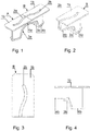
- Fig.1 -
- axonometric projection of two adjacent plug sockets for connecting contacting prefabricated elements,
- Fig.2 -
- axonometric projection of a plug socket;
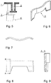
- Fig.3 -
- plug socket (top view);
- Fig.4 -
- plug socket (side view);
- Fig.5 -
- plug socket (cross section);
- Fig.6 -
- axonometric projection of a plug connector;
- Fig.7 -
- plug connector (top view);
- Fig.8 -
- plug connector (side view);
- Fig.9 -
- plug connector (cross section);
- Fig.10 -
- connection diagram of prefabricated elements positioned in-line (axonometric projection)
- Fig.11 -
- axonometric projection of three stages of inserting a plug connector with the profile of a sinusoidally bent plane in contacting plug sockets fitted in two adjacent prefabricated elements;
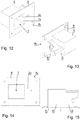
- Fig.12 -
- plug socket intended for connecting prefabricated elements positioned perpendicular to each other (front axonometric projection);
- Fig.13 -
- plug socket intended for connecting prefabricated elements positioned perpendicular to each other (rear axonometric projection);
- Fig.14 -
- plug socket intended for connecting prefabricated elements positioned perpendicular to each other (side view);
- Fig.15 -
- plug socket intended for connecting prefabricated elements positioned perpendicular to each other (top view);
- Fig.16 -
- connection diagram of perpendicular prefabricated elements (axonometric projection)
- Fig.17 -
- connection kit intended for connecting prefabricated elements positioned perpendicular to each other, with two wedges (front axonometric projection);
- Fig.18 -
- axonometric projection of a connection kit intended for connecting prefabricated elements positioned perpendicular to each other, with one wedge already hammered in and the other wedge ready for hammering;
- Fig.19 -
- axonometric projection of a connection kit intended for connecting prefabricated elements positioned perpendicular to each other, with wedges already hammered in the plug socket;
- Fig.20 -
- axonometric projection of a connection kit in the form of two reinforced adjacent plug sockets for connecting contacting prefabricated elements;
- Fig.21 -
- axonometric projection of a single plug socket, additionally reinforced;
- Fig.22 -
- cross-section view of two ferroconcrete panels connected by means of an additionally reinforced connecting kit.
- Fig. 23-41
- illustrate several solutions according to the state of the art.
- A manufacturing plant producing prefabricated elements for the construction industry was asked to manufacture a certain number of ferroconcrete elements of an energy-saving passive fully-detached house. As part of the assignment, the plant was asked to install a system for fast and easy connection of individual panels with one another.
- The connecting kit, consisting of a few components, had to be suitable both for in-line connection of two adjacent precast elements and for corner connections, i.e. those when two elements are perpendicular to each other.
- In the first embodiment of the connecting kit according to the invention, i.e. when the system is intended for in-line connections, the connecting kit consists of two plug sockets A and B installed in two precast panels Pa and Pb to be connected with each other and one flat plug connector S. Each of the plug sockets A and B, made of high-quality and high-strength plastics, is fitted with a flat element - 1a in the case of socket A and 1b in the case of socket B. Furthermore, both
flat elements gap internal gap 2 gradually decreases in the direction in which the plug connector S is being hammered in.
The plug connector S has been made of a high-grade steel and resembles a very low, wide and thick letter U with the profile a sinusoidally bent plane; the cross-section of the connector has the shape of a wedge tapering towards the end that is hammered into the plug sockets A, B. The purpose of the plug connector S is to transfer stress to the walls of thegap 2, simultaneously increasing the friction force and preventing the plug connector S from sliding out of the socket A and B.
Inside the recess formed in part of the plug socket A, B, located inside the connected element Pa, Pb, the socket has asemicircular cavity protective elements gap - In another embodiment of the same variant of the invention, used for in-line connections, the connecting kit Z is also formed by two plug sockets A and B, placed inside two precast panel elements Pa, Pb to be connected with each other, and by one flat plug connector S. As in the first embodiment, each of the plug sockets A and B is fitted with a flat element - 1a and 1b, respectively, and each of the plug sockets A and B has an internal smooth-surfaced
gap internal gap 2 gradually decreases in the direction in which the plug connector S is being hammered in.
In the embodiment discussed here, each of the plug sockets A, B has additionally been reinforced by the addition of arectangular metal plate plates gap socket
In addition, each of the plug sockets A, B has additionally been fitted with reinforcing elements that help strengthen the structure of the connection, in the form of adequately bent steel reinforcing bars.
Namely, crosswise reinforcingbars semicircular cavities bars 14a are hooked under thebar 13a, and twobars 14b are hooked under thebar 13b. Each of thebars 14a has one end that is bent downward in a hook-like fashion, whereas its other end is permanently fastened to the upper part of theplate 11a, while each of thebars 14b has one end that is bent downward in a hook-like fashion, whereas its other end is permanently fastened to the upper part of theplate 11b. Furthermore, thebars 14a (in the case of the plug socket A) and thebars 14b (in the case of the plug socket B), are secured from the top withcrosswise clamps bars
The lower part of theplate bars bars - In the other variant of the invention, the plug socket B, constituting the basic module, has been used as the basis for a plug socket B2 intended for corner connections.
In this case, the plug socket B, constituting a module, adheres with itsflat element 1b to acuboid chamber 5 embedded in the structure of a precast element. Theflat element 1b has aninternal gap 2b, shape-matched with a half of a sinusoidally shaped plug connector S. A rectangularflat element 6 is fastened to the wall of thecuboid chamber 5 located on the external plane of the precast element Pb intended to be connected. The surface of theflat element 6 has arectangular opening 7. The size of therectangular opening 7 corresponds to the size of a set of twowedges cuboid chamber 5 formed a cuboid filling 10 of thechamber 5 in the plug socket B2. Thanks to the wedges, hammering in the sinusoidally bent plug connector S into thegap 2 was easier, and the resulting filling 10 of thechamber 5 secured the plug connector S against sliding out. - Ferroconcrete precast elements with pre-installed connecting kits according to the invention were connected by the method according to the invention in a few stages.
At the preliminary stage, already in the precasting plant, two plug sockets were inserted on both sides of each precast element, depending on its intended use and function (i.e. parallel vs. corner element). Optionally these were the sockets A or sockets B or sockets B2. Importantly, the line running along the contact edges of the connected elements constituted the axis of symmetry of the sockets.
On the construction site, directly before connecting two adjacent precast elements Pa, Pb, further assembly operations depend on whether the two precast elements are to be connected in parallel or perpendicular to each other.
In the first variant, i.e. in parallel connection, two plug sockets A and B must be embedded in the structure of precast elements Pa and Pb. Both elements Pa, Pb had to be positioned so that their plug sockets - i.e. the socket A and the socket B - were on the opposite sides in the contact plane of the connected elements.
Then, the connector S was hammered into the adequately profiledgap 2, whose shape corresponded to the plug connector S with the profile of a sinusoidally bent plane, formed by the twoconnected gaps - The reinforced kit presented in the second embodiment was manufactured in the prefabrication plant by embedding two plug sockets A and B on both sides in the structure of each precast element Pa, Pb. Importantly, the plug sockets had been reinforced with
rectangular plates longitudinal bars clamps - In the other variant (i.e. perpendicular connection), two plug sockets A and B2 were embedded in the structure of the two precast plate elements Pa, Pb. Both plug sockets were made of metal.
Two elements positioned in perpendicular to each other were connected by means of the same, all-purpose plug connector S. The process of hammering-in the connector S was facilitated by the use of the twowedges wedges opening 7 to the inside of thecuboid chamber 5, thus forming its filling 10. Thewedges cuboid chamber 5 of the plug socket B2, ensured full deployment of the plug connector S which completely filled thegap 2a-2b and thus connected the two perpendicular elements Pa, Pb. -
- A -
- plug socket for in-line connections,
- B -
- plug socket for in-line connections,
- B2 -
- plug socket for corner (perpendicular) connections,
- Pa, Pb -
- prefabricated elements to be connected
- S -
- plug connector,
- Z -
- reinforcement of the prefabricated element
- 1 -
- flat rectangular element of the socket,
- 2 -
- internal gap shape-matched with a half of the plug connector S,
- 3 -
- semicircular cavity,
- 4 -
- flat protective element,
- 5 -
- chamber of plug socket B2,
- 6 -
- flat plate element of plug socket B2,
- 7 -
- chamber opening,
- 8 -
- wedge,
- 9 -
- wedge,
- 10 -
- chamber filling 5,
- 11a -
- rectangular metal plate for plug socket A,
- 11b -
- rectangular metal plate for plug socket B,
- 12a -
- gap in the rectangular metal plate for plug socket A,
- 12b -
- gap in the rectangular metal plate for plug socket B,
- 13a -
- crosswise reinforcing bar in plug socket A,
- 13b -
- crosswise reinforcing bar in plug socket B,
- 14a -
- longitudinal reinforcing bar in plug socket A,
- 14b -
- longitudinal reinforcing bar in plug socket B,
- 15a -
- crosswise reinforcing bar (clamp) in plug socket A,
- 15b -
- crosswise reinforcing bar (clamp) in plug socket B,
- 16a -
- longitudinal reinforcing bar in plug socket A,
- 16b -
- longitudinal reinforcing bar in plug socket B.
Claims (10)
- A connecting kit for fastening precast panel elements, constituting at least two-piece connection, one piece of which is positioned in the structure of one precast element and the other piece is positioned in the structure of an adjacent precast element, whereby such kit is fitted with a plug socket and a shape-matched connector which - by fitting in into the socket in use- integrates the two precast elements, wherein the kit consists of two plug sockets (A, B), adapted to be respectively embedded in one of the two panel elements to be connected with each other (Pa, Pb) and one flat plug connector (S) resembling a very low, wide and thick letter U with the profile of a sinusoidally bent plane, whereby the cross-section of the connector has the shape of a wedge tapering towards the end that is hammered into plug sockets (A, B), while each of the plug sockets (A, B) is fitted with a rectangular flat element (1a, 1b) situated in the part of the socket that is located in the external plane of the precast panel element to be connected (Pa, Pb) and has an internal gap (2a, 2b) whose shape matches in use a half of the plug connector (S), whereas the part of the plug socket (A, B) located inside the element to be connected has a semicircular cavity (3a, 3b) to accommodate a reinforcing bar (13a, 13b).
- A connecting kit according to claim 1 characterized in that its plug socket (B) and specifically its flat element (1b) touches a cuboid chamber (5) embedded in a panel element (Pb), constituting a side wall of the chamber (5), whereby the front plane of an empty wall of the chamber (5), also forming the external plane of the panel element (Pb), incorporates a rectangular flat plate element (6) whose rectangular opening (7) coincides with the surface of the front empty wall of the chamber (5).
- A connecting kit according to claim 2 characterized in that the size of the rectangular opening (7) corresponds to the size of a two combined wedges (8, 9) which - after having been hammered inside the chamber (5) form a cuboid filling (10).
- A connecting kit according to claim 1 or 2 characterized in that the gap (2a, 2b) has a smooth surface.
- A connecting kit according to claim 1 or 2 characterized in that the gap (2a, 2b) has a corrugated surface.
- A connecting kit according to claim 1 characterized in that each of the plug sockets (A, B) is fitted with an additional reinforcement in the shape of a rectangular metal plate (11a, 11b), whose surface is perpendicular to the surface of a flat element (1a, 1b), thus forming a contact plane of the two plug sockets (A, B).
- A connecting kit according to claim 6 characterized in that the upper part of each of the rectangular metal plates (11a, 11b) has a narrow gap (12a, 12b), whose width and height correspond to those of the internal gap (2a, 2b).
- A connecting kit according to claim 6 characterized in that each of the plug sockets (A, B) is fitted with reinforcing elements made of longitudinal reinforcing bars (14a, 14b, 16a, 16b) whose one end is connected to the metal plates (11a, 11b) and of crosswise reinforcing bars (13a, 13b, 15a, 15b), whereas the free ends of all bars are bent in a hook-like fashion.
- A connecting kit according to claim 8 characterized in that the reinforcement of the plug sockets (A, B) is connected with a reinforcement (Z) of the panel elements (Pa, Pb).
- A method of connecting precast panel elements using the connecting kit according to claims 1 through 9 wherein it consists of the following stages:- at a preliminary stage, already in the prefabrication plant, at least one plug socket (optionally socket (A) or socket (B) or socket (B2) constituting the basic module or a socket using the basic module with an adapter) is inserted inside the structure of each precast element depending on its intended use and function (parallel element or corner element), such socket being inserted so that the line that goes along the contact edge of the connected elements is their axis of symmetry,- on the construction site, immediately prior to connecting two adjacent precast elements, those elements are placed in relation to each other so that their plug sockets - socket (A) or socket (B) or socket (B2) are positioned on the opposite sides of their symmetry plane and are positioned in the contact plane of the elements to be connected,- in order to connect the elements, the connector (S) is hammered into profiled gap whose shape matches the plug connector (S), whereby the said gap is formed by the two connected gaps (2a) and (2b), positioned in the contact planes of the two elements, whereas additionally in the case of connecting perpendicular elements the process of hammering-in the connector (S) is facilitated by the use of two additional wedges (8, 9) which are hammered in through an opening (7) to the inside of the cuboid chamber (5), thus forming its filling (10).
Priority Applications (1)
| Application Number | Priority Date | Filing Date | Title |
|---|---|---|---|
| PL18460024T PL3486387T3 (en) | 2017-05-11 | 2018-04-25 | Connecting kit for prefabricated panels and fastening method using such kit |
Applications Claiming Priority (1)
| Application Number | Priority Date | Filing Date | Title |
|---|---|---|---|
| PL421564A PL421564A1 (en) | 2017-05-11 | 2017-05-11 | Connecting set for fixing slab, preferably reinforced concrete precast elements and method of joining them by means of this set |
Publications (2)
| Publication Number | Publication Date |
|---|---|
| EP3486387A1 EP3486387A1 (en) | 2019-05-22 |
| EP3486387B1 true EP3486387B1 (en) | 2020-09-09 |
Family
ID=62167268
Family Applications (1)
| Application Number | Title | Priority Date | Filing Date |
|---|---|---|---|
| EP18460024.5A Active EP3486387B1 (en) | 2017-05-11 | 2018-04-25 | Connecting kit for prefabricated panels and fastening method using such kit |
Country Status (2)
| Country | Link |
|---|---|
| EP (1) | EP3486387B1 (en) |
| PL (2) | PL421564A1 (en) |
Families Citing this family (1)
| Publication number | Priority date | Publication date | Assignee | Title |
|---|---|---|---|---|
| CN113550601A (en) * | 2021-05-14 | 2021-10-26 | 中建八局装饰工程有限公司 | Self-lifting assembly type construction method for high and large space internal curved surface decorative modeling steel truss |
Family Cites Families (8)
| Publication number | Priority date | Publication date | Assignee | Title |
|---|---|---|---|---|
| GB2028958B (en) * | 1978-08-19 | 1982-12-01 | Portakabin Ltd | Joining walls panels |
| CA1242558A (en) | 1987-11-23 | 1988-10-04 | Ronald A. Wrightman | Log joint and machine for forming log joint |
| DE8715783U1 (en) * | 1987-11-28 | 1988-01-14 | Correcta Gmbh, 3590 Bad Wildungen, De | |
| US5761862A (en) * | 1995-10-03 | 1998-06-09 | Hendershot; Gary L. | Precast concrete construction and construction method |
| PL179763B1 (en) | 1996-06-27 | 2000-10-31 | Jacek Lubinski | Set of building units for erection of walls and floors |
| JP2002030729A (en) * | 2000-07-18 | 2002-01-31 | Kaieitechno Co Ltd | Joint metal fitting for concrete products |
| PL215834B1 (en) | 2008-04-09 | 2014-02-28 | Jaroslaw Gruszecki | Facade plate elements fixing kit |
| AT509682B1 (en) * | 2010-04-09 | 2012-02-15 | Lb Engineering Gmbh | CONNECTING ELEMENT FOR MANUFACTURED ELEMENTS |
-
2017
- 2017-05-11 PL PL421564A patent/PL421564A1/en unknown
-
2018
- 2018-04-25 EP EP18460024.5A patent/EP3486387B1/en active Active
- 2018-04-25 PL PL18460024T patent/PL3486387T3/en unknown
Non-Patent Citations (1)
| Title |
|---|
| None * |
Also Published As
| Publication number | Publication date |
|---|---|
| EP3486387A1 (en) | 2019-05-22 |
| PL421564A1 (en) | 2018-11-19 |
| PL3486387T3 (en) | 2021-06-14 |
Similar Documents
| Publication | Publication Date | Title |
|---|---|---|
| US6880304B1 (en) | Structural thermal framing and panel system for assembling finished or unfinished walls with multiple panel combinations for poured and nonpoured walls | |
| US9175466B2 (en) | Tension reinforcement for concrete | |
| CA2191914C (en) | Insulated concrete form | |
| US20070017176A1 (en) | Masonry wall system | |
| US6584750B1 (en) | Wall and method of constructing a wall comprising first, second, and end modules and a connection means for tying adjoining modules together in tension | |
| US20190169844A1 (en) | Pre-cast concrete formwork, wall system and method of construction | |
| WO2015192179A1 (en) | Formwork | |
| EP0399114A1 (en) | Shuttering for use in building construction | |
| EP3486387B1 (en) | Connecting kit for prefabricated panels and fastening method using such kit | |
| WO2008004852A1 (en) | Vertical construction joints | |
| US20170016237A1 (en) | Assembly and Method for Creating a Wall from a Flowable Material | |
| WO2014076716A1 (en) | A wall system of parallelepiped precast building panel | |
| WO2006032078A1 (en) | Modular construction system and method | |
| HUE027970T2 (en) | System of formwork blocks, structure constructed with same and method for constructing a structure | |
| US20060185283A1 (en) | Interlocking construction panel showing fabrication thereof and the building system | |
| WO2006056969A1 (en) | Prefabricated concrete wall panel and method of manufacture | |
| KR101413551B1 (en) | Clip unit for building materials | |
| KR102311736B1 (en) | Beam Assembly for supporting slave pannel | |
| WO2017100854A1 (en) | Connection system | |
| KR100619447B1 (en) | A walls and ceiling structure and construction method thereof | |
| WO2023223306A1 (en) | External walls and methods of constructing and cladding same | |
| US6829870B2 (en) | Building methods | |
| CA2897323C (en) | Assembly and method for creating a wall from a flowable material | |
| KR200198525Y1 (en) | Wood wall form remove tool | |
| KR200306741Y1 (en) | The mold prefabricated concrete |
Legal Events
| Date | Code | Title | Description |
|---|---|---|---|
| STAA | Information on the status of an ep patent application or granted ep patent |
Free format text: STATUS: UNKNOWN |
|
| PUAI | Public reference made under article 153(3) epc to a published international application that has entered the european phase |
Free format text: ORIGINAL CODE: 0009012 |
|
| STAA | Information on the status of an ep patent application or granted ep patent |
Free format text: STATUS: THE APPLICATION HAS BEEN PUBLISHED |
|
| AK | Designated contracting states |
Kind code of ref document: A1 Designated state(s): AL AT BE BG CH CY CZ DE DK EE ES FI FR GB GR HR HU IE IS IT LI LT LU LV MC MK MT NL NO PL PT RO RS SE SI SK SM TR |
|
| AX | Request for extension of the european patent |
Extension state: BA ME |
|
| STAA | Information on the status of an ep patent application or granted ep patent |
Free format text: STATUS: REQUEST FOR EXAMINATION WAS MADE |
|
| 17P | Request for examination filed |
Effective date: 20191121 |
|
| RBV | Designated contracting states (corrected) |
Designated state(s): AL AT BE BG CH CY CZ DE DK EE ES FI FR GB GR HR HU IE IS IT LI LT LU LV MC MK MT NL NO PL PT RO RS SE SI SK SM TR |
|
| RIC1 | Information provided on ipc code assigned before grant |
Ipc: E04B 1/48 20060101ALI20200204BHEP Ipc: F16B 5/00 20060101ALN20200204BHEP Ipc: E04B 1/04 20060101AFI20200204BHEP Ipc: E01C 11/14 20060101ALI20200204BHEP Ipc: E04B 1/61 20060101ALI20200204BHEP Ipc: E04B 1/41 20060101ALI20200204BHEP |
|
| GRAP | Despatch of communication of intention to grant a patent |
Free format text: ORIGINAL CODE: EPIDOSNIGR1 |
|
| STAA | Information on the status of an ep patent application or granted ep patent |
Free format text: STATUS: GRANT OF PATENT IS INTENDED |
|
| INTG | Intention to grant announced |
Effective date: 20200320 |
|
| RIC1 | Information provided on ipc code assigned before grant |
Ipc: E01C 11/14 20060101ALI20200311BHEP Ipc: E04B 1/61 20060101ALI20200311BHEP Ipc: E04B 1/04 20060101AFI20200311BHEP Ipc: F16B 5/00 20060101ALN20200311BHEP Ipc: E04B 1/48 20060101ALI20200311BHEP Ipc: E04B 1/41 20060101ALI20200311BHEP |
|
| GRAS | Grant fee paid |
Free format text: ORIGINAL CODE: EPIDOSNIGR3 |
|
| GRAA | (expected) grant |
Free format text: ORIGINAL CODE: 0009210 |
|
| STAA | Information on the status of an ep patent application or granted ep patent |
Free format text: STATUS: THE PATENT HAS BEEN GRANTED |
|
| AK | Designated contracting states |
Kind code of ref document: B1 Designated state(s): AL AT BE BG CH CY CZ DE DK EE ES FI FR GB GR HR HU IE IS IT LI LT LU LV MC MK MT NL NO PL PT RO RS SE SI SK SM TR |
|
| REG | Reference to a national code |
Ref country code: GB Ref legal event code: FG4D |
|
| REG | Reference to a national code |
Ref country code: AT Ref legal event code: REF Ref document number: 1311741 Country of ref document: AT Kind code of ref document: T Effective date: 20200915 Ref country code: CH Ref legal event code: EP |
|
| REG | Reference to a national code |
Ref country code: IE Ref legal event code: FG4D |
|
| REG | Reference to a national code |
Ref country code: DE Ref legal event code: R096 Ref document number: 602018007686 Country of ref document: DE |
|
| REG | Reference to a national code |
Ref country code: SE Ref legal event code: TRGR |
|
| REG | Reference to a national code |
Ref country code: LT Ref legal event code: MG4D |
|
| PG25 | Lapsed in a contracting state [announced via postgrant information from national office to epo] |
Ref country code: GR Free format text: LAPSE BECAUSE OF FAILURE TO SUBMIT A TRANSLATION OF THE DESCRIPTION OR TO PAY THE FEE WITHIN THE PRESCRIBED TIME-LIMIT Effective date: 20201210 Ref country code: LT Free format text: LAPSE BECAUSE OF FAILURE TO SUBMIT A TRANSLATION OF THE DESCRIPTION OR TO PAY THE FEE WITHIN THE PRESCRIBED TIME-LIMIT Effective date: 20200909 Ref country code: FI Free format text: LAPSE BECAUSE OF FAILURE TO SUBMIT A TRANSLATION OF THE DESCRIPTION OR TO PAY THE FEE WITHIN THE PRESCRIBED TIME-LIMIT Effective date: 20200909 Ref country code: HR Free format text: LAPSE BECAUSE OF FAILURE TO SUBMIT A TRANSLATION OF THE DESCRIPTION OR TO PAY THE FEE WITHIN THE PRESCRIBED TIME-LIMIT Effective date: 20200909 Ref country code: NO Free format text: LAPSE BECAUSE OF FAILURE TO SUBMIT A TRANSLATION OF THE DESCRIPTION OR TO PAY THE FEE WITHIN THE PRESCRIBED TIME-LIMIT Effective date: 20201209 Ref country code: BG Free format text: LAPSE BECAUSE OF FAILURE TO SUBMIT A TRANSLATION OF THE DESCRIPTION OR TO PAY THE FEE WITHIN THE PRESCRIBED TIME-LIMIT Effective date: 20201209 |
|
| REG | Reference to a national code |
Ref country code: AT Ref legal event code: MK05 Ref document number: 1311741 Country of ref document: AT Kind code of ref document: T Effective date: 20200909 |
|
| REG | Reference to a national code |
Ref country code: NL Ref legal event code: MP Effective date: 20200909 |
|
| PG25 | Lapsed in a contracting state [announced via postgrant information from national office to epo] |
Ref country code: RS Free format text: LAPSE BECAUSE OF FAILURE TO SUBMIT A TRANSLATION OF THE DESCRIPTION OR TO PAY THE FEE WITHIN THE PRESCRIBED TIME-LIMIT Effective date: 20200909 Ref country code: LV Free format text: LAPSE BECAUSE OF FAILURE TO SUBMIT A TRANSLATION OF THE DESCRIPTION OR TO PAY THE FEE WITHIN THE PRESCRIBED TIME-LIMIT Effective date: 20200909 |
|
| PG25 | Lapsed in a contracting state [announced via postgrant information from national office to epo] |
Ref country code: EE Free format text: LAPSE BECAUSE OF FAILURE TO SUBMIT A TRANSLATION OF THE DESCRIPTION OR TO PAY THE FEE WITHIN THE PRESCRIBED TIME-LIMIT Effective date: 20200909 Ref country code: CZ Free format text: LAPSE BECAUSE OF FAILURE TO SUBMIT A TRANSLATION OF THE DESCRIPTION OR TO PAY THE FEE WITHIN THE PRESCRIBED TIME-LIMIT Effective date: 20200909 Ref country code: RO Free format text: LAPSE BECAUSE OF FAILURE TO SUBMIT A TRANSLATION OF THE DESCRIPTION OR TO PAY THE FEE WITHIN THE PRESCRIBED TIME-LIMIT Effective date: 20200909 Ref country code: PT Free format text: LAPSE BECAUSE OF FAILURE TO SUBMIT A TRANSLATION OF THE DESCRIPTION OR TO PAY THE FEE WITHIN THE PRESCRIBED TIME-LIMIT Effective date: 20210111 Ref country code: SM Free format text: LAPSE BECAUSE OF FAILURE TO SUBMIT A TRANSLATION OF THE DESCRIPTION OR TO PAY THE FEE WITHIN THE PRESCRIBED TIME-LIMIT Effective date: 20200909 |
|
| PG25 | Lapsed in a contracting state [announced via postgrant information from national office to epo] |
Ref country code: AT Free format text: LAPSE BECAUSE OF FAILURE TO SUBMIT A TRANSLATION OF THE DESCRIPTION OR TO PAY THE FEE WITHIN THE PRESCRIBED TIME-LIMIT Effective date: 20200909 Ref country code: AL Free format text: LAPSE BECAUSE OF FAILURE TO SUBMIT A TRANSLATION OF THE DESCRIPTION OR TO PAY THE FEE WITHIN THE PRESCRIBED TIME-LIMIT Effective date: 20200909 Ref country code: ES Free format text: LAPSE BECAUSE OF FAILURE TO SUBMIT A TRANSLATION OF THE DESCRIPTION OR TO PAY THE FEE WITHIN THE PRESCRIBED TIME-LIMIT Effective date: 20200909 Ref country code: IS Free format text: LAPSE BECAUSE OF FAILURE TO SUBMIT A TRANSLATION OF THE DESCRIPTION OR TO PAY THE FEE WITHIN THE PRESCRIBED TIME-LIMIT Effective date: 20210109 |
|
| REG | Reference to a national code |
Ref country code: DE Ref legal event code: R097 Ref document number: 602018007686 Country of ref document: DE |
|
| PG25 | Lapsed in a contracting state [announced via postgrant information from national office to epo] |
Ref country code: SK Free format text: LAPSE BECAUSE OF FAILURE TO SUBMIT A TRANSLATION OF THE DESCRIPTION OR TO PAY THE FEE WITHIN THE PRESCRIBED TIME-LIMIT Effective date: 20200909 |
|
| PLBE | No opposition filed within time limit |
Free format text: ORIGINAL CODE: 0009261 |
|
| STAA | Information on the status of an ep patent application or granted ep patent |
Free format text: STATUS: NO OPPOSITION FILED WITHIN TIME LIMIT |
|
| 26N | No opposition filed |
Effective date: 20210610 |
|
| PG25 | Lapsed in a contracting state [announced via postgrant information from national office to epo] |
Ref country code: DK Free format text: LAPSE BECAUSE OF FAILURE TO SUBMIT A TRANSLATION OF THE DESCRIPTION OR TO PAY THE FEE WITHIN THE PRESCRIBED TIME-LIMIT Effective date: 20200909 Ref country code: SI Free format text: LAPSE BECAUSE OF FAILURE TO SUBMIT A TRANSLATION OF THE DESCRIPTION OR TO PAY THE FEE WITHIN THE PRESCRIBED TIME-LIMIT Effective date: 20200909 |
|
| PG25 | Lapsed in a contracting state [announced via postgrant information from national office to epo] |
Ref country code: IT Free format text: LAPSE BECAUSE OF FAILURE TO SUBMIT A TRANSLATION OF THE DESCRIPTION OR TO PAY THE FEE WITHIN THE PRESCRIBED TIME-LIMIT Effective date: 20200909 |
|
| PG25 | Lapsed in a contracting state [announced via postgrant information from national office to epo] |
Ref country code: MC Free format text: LAPSE BECAUSE OF FAILURE TO SUBMIT A TRANSLATION OF THE DESCRIPTION OR TO PAY THE FEE WITHIN THE PRESCRIBED TIME-LIMIT Effective date: 20200909 |
|
| PG25 | Lapsed in a contracting state [announced via postgrant information from national office to epo] |
Ref country code: LU Free format text: LAPSE BECAUSE OF NON-PAYMENT OF DUE FEES Effective date: 20210425 |
|
| PG25 | Lapsed in a contracting state [announced via postgrant information from national office to epo] |
Ref country code: LI Free format text: LAPSE BECAUSE OF NON-PAYMENT OF DUE FEES Effective date: 20210430 Ref country code: CH Free format text: LAPSE BECAUSE OF NON-PAYMENT OF DUE FEES Effective date: 20210430 |
|
| PG25 | Lapsed in a contracting state [announced via postgrant information from national office to epo] |
Ref country code: IE Free format text: LAPSE BECAUSE OF NON-PAYMENT OF DUE FEES Effective date: 20210425 |
|
| PG25 | Lapsed in a contracting state [announced via postgrant information from national office to epo] |
Ref country code: IS Free format text: LAPSE BECAUSE OF FAILURE TO SUBMIT A TRANSLATION OF THE DESCRIPTION OR TO PAY THE FEE WITHIN THE PRESCRIBED TIME-LIMIT Effective date: 20210109 |
|
| PG25 | Lapsed in a contracting state [announced via postgrant information from national office to epo] |
Ref country code: NL Free format text: LAPSE BECAUSE OF NON-PAYMENT OF DUE FEES Effective date: 20200923 Ref country code: CY Free format text: LAPSE BECAUSE OF FAILURE TO SUBMIT A TRANSLATION OF THE DESCRIPTION OR TO PAY THE FEE WITHIN THE PRESCRIBED TIME-LIMIT Effective date: 20200909 |
|
| PG25 | Lapsed in a contracting state [announced via postgrant information from national office to epo] |
Ref country code: HU Free format text: LAPSE BECAUSE OF FAILURE TO SUBMIT A TRANSLATION OF THE DESCRIPTION OR TO PAY THE FEE WITHIN THE PRESCRIBED TIME-LIMIT; INVALID AB INITIO Effective date: 20180425 |
|
| PGFP | Annual fee paid to national office [announced via postgrant information from national office to epo] |
Ref country code: FR Payment date: 20230424 Year of fee payment: 6 Ref country code: DE Payment date: 20230420 Year of fee payment: 6 |
|
| PGFP | Annual fee paid to national office [announced via postgrant information from national office to epo] |
Ref country code: SE Payment date: 20230420 Year of fee payment: 6 Ref country code: PL Payment date: 20230414 Year of fee payment: 6 |
|
| PGFP | Annual fee paid to national office [announced via postgrant information from national office to epo] |
Ref country code: BE Payment date: 20230419 Year of fee payment: 6 |
|
| PGFP | Annual fee paid to national office [announced via postgrant information from national office to epo] |
Ref country code: GB Payment date: 20230419 Year of fee payment: 6 |