EP3486112A1 - Vehicle seat with guide unit - Google Patents
Vehicle seat with guide unit Download PDFInfo
- Publication number
- EP3486112A1 EP3486112A1 EP18201430.8A EP18201430A EP3486112A1 EP 3486112 A1 EP3486112 A1 EP 3486112A1 EP 18201430 A EP18201430 A EP 18201430A EP 3486112 A1 EP3486112 A1 EP 3486112A1
- Authority
- EP
- European Patent Office
- Prior art keywords
- vehicle seat
- lever element
- pivot axis
- lever
- seat upper
- Prior art date
- Legal status (The legal status is an assumption and is not a legal conclusion. Google has not performed a legal analysis and makes no representation as to the accuracy of the status listed.)
- Granted
Links
- 230000000087 stabilizing effect Effects 0.000 claims abstract description 9
- 239000000725 suspension Substances 0.000 claims description 18
- 238000013016 damping Methods 0.000 description 3
- 230000006641 stabilisation Effects 0.000 description 2
- 238000011105 stabilization Methods 0.000 description 2
- 239000003381 stabilizer Substances 0.000 description 1
Images


Classifications
-
- B—PERFORMING OPERATIONS; TRANSPORTING
- B60—VEHICLES IN GENERAL
- B60N—SEATS SPECIALLY ADAPTED FOR VEHICLES; VEHICLE PASSENGER ACCOMMODATION NOT OTHERWISE PROVIDED FOR
- B60N2/00—Seats specially adapted for vehicles; Arrangement or mounting of seats in vehicles
- B60N2/02—Seats specially adapted for vehicles; Arrangement or mounting of seats in vehicles the seat or part thereof being movable, e.g. adjustable
- B60N2/04—Seats specially adapted for vehicles; Arrangement or mounting of seats in vehicles the seat or part thereof being movable, e.g. adjustable the whole seat being movable
- B60N2/16—Seats specially adapted for vehicles; Arrangement or mounting of seats in vehicles the seat or part thereof being movable, e.g. adjustable the whole seat being movable height-adjustable
- B60N2/1605—Seats specially adapted for vehicles; Arrangement or mounting of seats in vehicles the seat or part thereof being movable, e.g. adjustable the whole seat being movable height-adjustable characterised by the cinematic
- B60N2/161—Rods
- B60N2/1615—Parallelogram-like structure
-
- B—PERFORMING OPERATIONS; TRANSPORTING
- B60—VEHICLES IN GENERAL
- B60N—SEATS SPECIALLY ADAPTED FOR VEHICLES; VEHICLE PASSENGER ACCOMMODATION NOT OTHERWISE PROVIDED FOR
- B60N2/00—Seats specially adapted for vehicles; Arrangement or mounting of seats in vehicles
- B60N2/02—Seats specially adapted for vehicles; Arrangement or mounting of seats in vehicles the seat or part thereof being movable, e.g. adjustable
- B60N2/04—Seats specially adapted for vehicles; Arrangement or mounting of seats in vehicles the seat or part thereof being movable, e.g. adjustable the whole seat being movable
- B60N2/16—Seats specially adapted for vehicles; Arrangement or mounting of seats in vehicles the seat or part thereof being movable, e.g. adjustable the whole seat being movable height-adjustable
- B60N2/1635—Seats specially adapted for vehicles; Arrangement or mounting of seats in vehicles the seat or part thereof being movable, e.g. adjustable the whole seat being movable height-adjustable characterised by the drive mechanism
- B60N2/1665—Hydraulic or pneumatic actuation
-
- B—PERFORMING OPERATIONS; TRANSPORTING
- B60—VEHICLES IN GENERAL
- B60N—SEATS SPECIALLY ADAPTED FOR VEHICLES; VEHICLE PASSENGER ACCOMMODATION NOT OTHERWISE PROVIDED FOR
- B60N2/00—Seats specially adapted for vehicles; Arrangement or mounting of seats in vehicles
- B60N2/50—Seat suspension devices
- B60N2/502—Seat suspension devices attached to the base of the seat
-
- B—PERFORMING OPERATIONS; TRANSPORTING
- B60—VEHICLES IN GENERAL
- B60N—SEATS SPECIALLY ADAPTED FOR VEHICLES; VEHICLE PASSENGER ACCOMMODATION NOT OTHERWISE PROVIDED FOR
- B60N2/00—Seats specially adapted for vehicles; Arrangement or mounting of seats in vehicles
- B60N2/50—Seat suspension devices
- B60N2/506—Seat guided by rods
- B60N2/507—Parallelogram-like structure
Definitions
- the invention relates to a vehicle seat with a vehicle seat upper part, a vehicle seat bottom part and a guide device for guiding the vehicle seat upper part relative to the vehicle seat bottom part in a deflection of the vehicle seat upper part relative to the vehicle seat upper part.
- a large number of such guide devices are known from the prior art, for example a guide device in the form of a parallelogram, as used in so-called parallelogram suspensions of a vehicle seat.
- Parallelogram suspensions are vertical suspensions, with a vertical suspension of the vehicle seat upper at the same time being offset forwards or backwards, which however is only desired under certain conditions.
- the guide device comprises a first arrangement and a second arrangement, wherein the respective lever elements are arranged to extend either forwardly or rearwardly.
- One of the arrangements is therefore similar to the previously known parallelogram arrangement.
- lever elements of the first arrangement run differently than the lever elements of the second arrangement, it is achieved that the offset of the vehicle seat upper part is compensated to the rear or front and the guide device only allows movement of the vehicle seat upper part in the vertical direction.
- the stabilizer is connected to each of these elements, that is, both the vehicle seat top, the vehicle seat bottom and the guide means.
- the guide device therefore has three lever elements, which are arranged accordingly.
- the first lever element by means of a first pivot axis and the second lever element by means of a second pivot axis pivotally connected to the vehicle seat bottom and the third lever member by means of a third pivot axis and the fourth lever member by means of a fourth pivot axis pivotally connected to the vehicle seat top.
- the second lever element, the fourth lever element and the lever element connection are pivotably connected by means of a sixth pivot axis and the first lever element, the third lever element and the lever element connection by means of a fifth pivot axis, wherein the seventh lever element is pivotally mounted on the sixth pivot axis.
- the lever element connection is to be regarded as a whole as a component of the first arrangement and the second arrangement. Such an element is necessary because the lever member connection for the first assembly and the second assembly virtually takes over the role of the vehicle seat top and the vehicle seat bottom.
- lever element connection is pivotally connected both to the lever elements of the first arrangement and to the lever elements of the second arrangement.
- the stabilizing device must be pivotally connected to the lever element connection.
- the fifth lever element is pivotally connected to the vehicle seat upper part by means of the third pivot axis.
- the arrangement of the stabilization device can be described in more detail by the sixth lever element is pivotally connected by means of a seventh pivot axis with the vehicle seat bottom.
- a suspension unit for springs of the deflection of the vehicle seat upper part is provided, which is preferably connected to the vehicle seat upper part and the vehicle seat bottom.
- a damping unit is provided for damping the deflection of the vehicle seat upper part.
- a non-deflected position is a position of the guide means to understand, in which no external force acts on the guide device or the vehicle seat, that is, that no deflection of the vehicle seat upper part is performed.
- a deflected position means a position of the guide device in which the vehicle seat upper part has been deflected relative to the vehicle seat bottom part.
- the maximum or minimum deflection of the vehicle seat upper part relative to the vehicle seat base which positions may also be referred to as the maximum deflected position and minimal deflected position.
- the third pivot axis is arranged above the first pivot axis and the fourth pivot axis is arranged above the second pivot axis.
- the distance of the first pivot axis to the third pivot axis is equal to the distance of the second pivot axis to the fourth pivot axis, in the undeflected position.
- the seventh pivot axis is arranged in the longitudinal direction between the first pivot axis and the second pivot axis.
- the lever element connection is designed such that the length of the lever element connection can be changed by the deflection of the vehicle seat upper part.
- the guide changes through the guide device, so that not only more vertical movement is possible, but at the same time a rotation of the vehicle seat upper part is performed so that the vehicle seat upper part and the vehicle seat bottom part enclose an angle which is smaller than 180 °. It can therefore be achieved a two-dimensional suspension, on the one hand in the vertical direction and a rotationally acting longitudinal horizontal suspension.
- the fifth lever element is designed such that the fifth lever element is variable in its length by the deflection of the vehicle seat upper part.
- an offset of the vehicle seat upper part is achieved in the longitudinal direction. It can therefore also be achieved a two-dimensional suspension, on the one hand in the vertical direction and a translationally acting longitudinal horizontal suspension.
- lever element connection or the fifth lever element may be formed as a damper element.
- a vehicle seat 1 is shown, with a vehicle seat upper part 2 and a vehicle seat bottom part 3, wherein a seat part 24 and a backrest 25 connected to the seat part 24 are arranged on the vehicle seat upper part 2.
- a guide device 4 connected to the vehicle seat upper part 2 and the vehicle seat lower part 3 can be seen, and more preferably also a suspension unit 23 can be seen, which is likewise connected to the vehicle seat upper part 2 and the vehicle seat bottom part 3.
- FIGS. 2A to 2C show schematically the guide device 4 according to a first embodiment, wherein the FIG. 2A the guide device 4 in a non-deflected position P1, the FIG. 2B a maximum deflected position P2 and the Figure 2C a minimally deflected position P3 shows.
- the first arrangement 5 and the second arrangement 6 can be seen in particular, the first arrangement 5 having a first lever element 7 extending forwards in the longitudinal direction L and a second lever element 8 extending forwards in the longitudinal direction L and a lever element connection 14, and wherein the second Arrangement 6 in the longitudinal direction L after Has third extending rear lever element 9 and a longitudinally extending rearward third lever element 10.
- a stabilizing device 15 which has a fifth lever element 11, a sixth lever element 12 and a seventh lever element 13.
- each lever element has a first end portion 26 and a second end portion 27, wherein each of these end portions 26, 27 is connected to an associated pivot axis, in particular the figures can be seen.
- the end regions 26, 27 are shown by way of example only for a lever element.
- the lever elements 7, 8, 9, 10, 11, 12, 13 are each elongate.
- the lever elements 7, 8, 9, 10, 11, 12, 13 are arranged as follows:
- the first lever element 7 is pivotably connected to the vehicle seat bottom 3 by means of a first pivot axis 16 and the second lever element 8 by means of a second pivot axis 17.
- the third lever member 9 is pivotally connected by means of a third pivot axis 18 and the fourth lever member 10 by means of a fourth pivot axis 19 with the vehicle seat upper part 2.
- the second lever element 8, the four lever element 10 and the lever element connection 14 are pivotably connected by means of a sixth pivot axis 21, the first lever element 7, the third lever element 9 and the lever element connection 14 being pivotably connected by means of a fifth pivot axis 20.
- the fifth lever member 11, the sixth lever member 12 and the seventh lever member 13 are pivotally connected to each other by means of a common pivot axis 22.
- the sixth lever element 12 is connected by means of a seventh pivot axis 28 pivotally connected to the vehicle seat bottom.
- the seventh lever member 13 is pivotally mounted on the sixth pivot axis 21.
- the guide device 4 in the non-deflected position P1, that is, that no external force on the vehicle seat 1 and the Vehicle seat upper part 2 acts, which would cause a deflection of the vehicle seat upper part 2 relative to the vehicle seat bottom part 3.
- first lever member 7 and the second lever member 8 are arranged to extend in the longitudinal direction L forward and also parallel to each other.
- Parallel is to be understood that the connecting line between the first pivot axis 16 and the fifth pivot axis and the connecting line between the second pivot axis 17 and the sixth pivot axis 21 are formed parallel to each other.
- This also applies analogously to the third lever element 9 and the fourth lever element 10 with the corresponding pivot axes 18, 19, 20, 21.
- the connecting line between the fifth pivot axis 20 and the sixth pivot axis 21 is parallel to the connecting line between the first pivot axis 16 and the second pivot axis 17 and the connecting line between the third pivot axis 18 and the fourth pivot axis 19.
- the lever element connection 14 is formed parallel to the vehicle seat upper part 2 and the vehicle seat bottom 3.
- the first lever element 7, the second lever element 8, the third lever element 9 and the fourth lever element 10 are of equal length, that is, the lengths of the connecting lines between the respective pivot axes of the lever elements are the same length.
- connecting line between the third pivot axis 18 and the common pivot axis 22 has the same length as the connecting line between the first pivot axis 16 and the second pivot axis 17.
- the connecting line between the common pivot axis 22 and the seventh pivot axis 28 has the same length as the connecting line between the seventh pivot axis 28 and the second pivot axis 17. Accordingly, the length of the connecting line between the common pivot axis 22 and sixth pivot axis 21 equal to the length of the connecting line of the first, second, third or fourth lever element.
- the lengths of the connecting lines should be designed such that a complete deflection or a minimum deflection is possible.
- a suspension unit 23 is also provided, which can be realized for example as an air spring or as a mechanical spring.
- the third pivot axis 18 is disposed above the first pivot axis 16 and the fourth pivot axis 19 above the second pivot axis 17, viewed in the height direction H, wherein in particular no offset in the longitudinal direction L is provided forward or backward.
- the guide device 4 is shown in a maximum deflected position P2, wherein the elements have the same reference numerals.
- the guide device 4 is shown in a minimally deflected position P3 and in a cross-section for an improved representation, whereby here too the elements have the same reference numerals.
- FIG. 3 is the guide device 4 of FIG. 2A shown in a schematic and perspective view.
- FIG. 4 shows a guide device 4 with the same components as the guide device of Figures 2A-2C
- the lever elements of the first assembly 5 and the second arrangement are oriented differently, that is, the first lever member 7 and the second lever member 8 in the longitudinal direction L to the rear and the third lever member 9 and the fourth lever member 10 in the longitudinal direction L forward are arranged.
- variable lever element connection 14 ' may be formed as a damper element.
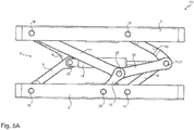
- FIG. 5B shows the guide device 4 in the maximum deflected position P2 and the FIG. 5C the guide device 4 in the minimum deflected position P3.
- a rotation of the vehicle seat upper part 2 is caused by the change in length of the lever element connection 14 ', wherein a change in length is equivalent to a change in the distance between the fifth pivot axis 20 and the sixth pivot axis 21st
- This and the positive guidance by the stabilization device 15 result in different movements within the guide device 4.
- the rotation of the vehicle seat upper part 2 also results in a corresponding offset in the longitudinal direction L to the front or to the rear, depending on the type of movement or deflection of the vehicle seat upper part 2.
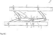
- FIGS. 6A-6C show a further embodiment in which the fifth lever element 11, which according to the Figures 2A-2C not variable in length, replaced by a variable in length lever member 11 '.
- the FIG. 6A shows the guide device in the undeflected position P1, the FIG. 6B in the maximum deflected position P2 and the FIG. 6C in the minimum deflected position P3.
- each lever element 7, 8, 9, 10, 11, 12, 13 and the lever element connection 14 and the distance between the pivot axes 16, 17 and the pivot axes 18, 19 can be made variable in length.
- Combinations are also conceivable of lever elements which are variable in their length, for example the fifth lever element 12 and the lever element connection 14, or any other combination of the lever elements 7, 8, 9, 10, 11, 12, 13 and the lever element connection 14.
- each other lever element may be variable in its length.
Landscapes
- Engineering & Computer Science (AREA)
- Aviation & Aerospace Engineering (AREA)
- Transportation (AREA)
- Mechanical Engineering (AREA)
- Seats For Vehicles (AREA)
Abstract
Fahrzeugsitz mit einem Fahrzeugsitzoberteil, einem Fahrzeugsitzunterteil und einer Führungseinrichtung zum Führen des Fahrzeugsitzoberteils gegenüber dem Fahrzeugsitzunterteil bei einer Auslenkung des Fahrzeugsitzoberteils relativ zu dem Fahrzeugsitzunterteil,
dadurch gekennzeichnet, dass
die Führungseinrichtung umfasst:
- Eine erste Anordnung mit einem ersten Hebelelement, einem zweiten Hebelelement und einer Hebelelementverbindung, wobei das erste Hebelelement und das zweite Hebelelement in einer Längsrichtung nach vorne verlaufend angeordnet sind;
- Eine zweite Anordnung mit einem dritten Hebelelement, einem vierten Hebelelement und der Hebelelementverbindung, wobei das dritte Hebelelement und das vierte Hebelelement in einer Längsrichtung nach hinten verlaufend angeordnet sind;
- Eine Stabilisierungseinrichtung mit einem fünften Hebelelement, einem sechsten Hebelelement und einem siebten Hebelelement, welche mittels einer gemeinsamen Schwenkachse schwenkbar verbunden sind;
wobei das fünfte Hebelelement mit dem Fahrzeugsitzoberteil, das sechste Hebelelement mit dem Fahrzeugsitzunterteil und das siebte Hebelelement mit der Hebelelementverbindung schwenkbar verbunden sind.

characterized in that
the management facility comprises:
A first arrangement having a first lever element, a second lever element and a lever element connection, wherein the first lever element and the second lever element are arranged to extend forward in a longitudinal direction;
A second arrangement comprising a third lever element, a fourth lever element and the lever element connection, wherein the third lever element and the fourth lever element are arranged running backwards in a longitudinal direction;
- A stabilizing device having a fifth lever element, a sixth lever element and a seventh lever element, which are pivotally connected by means of a common pivot axis;
wherein the fifth lever member is pivotally connected to the vehicle seat top, the sixth lever member to the vehicle seat bottom and the seventh lever member to the lever member connection.
Description
Die Erfindung betrifft einen Fahrzeugsitz mit einem Fahrzeugsitzoberteil, einem Fahrzeugsitzunterteil und einer Führungseinrichtung zum Führen des Fahrzeugsitzoberteils gegenüber dem Fahrzeugsitzunterteil bei einer Auslenkung des Fahrzeugsitzoberteils relativ zu dem Fahrzeugsitzoberteil.The invention relates to a vehicle seat with a vehicle seat upper part, a vehicle seat bottom part and a guide device for guiding the vehicle seat upper part relative to the vehicle seat bottom part in a deflection of the vehicle seat upper part relative to the vehicle seat upper part.
Aus dem Stand der Technik ist eine Vielzahl von derartigen Führungseinrichtungen bekannt, beispielsweise eine Führungseinrichtung in Form eines Parallelogramms, wie es bei sogenannten Parallelogrammfederungen eines Fahrzeugsitzes Einsatz finden.A large number of such guide devices are known from the prior art, for example a guide device in the form of a parallelogram, as used in so-called parallelogram suspensions of a vehicle seat.
Bei Parallelogrammfederungen handelt es sich um Vertikalfederungen, wobei bei einer vertikalen Federung des Fahrzeugsitzoberteils gleichzeitig ein Versatz nach vorne oder hinten stattfindet, welcher jedoch nur unter bestimmten Voraussetzungen erwünscht ist.Parallelogram suspensions are vertical suspensions, with a vertical suspension of the vehicle seat upper at the same time being offset forwards or backwards, which however is only desired under certain conditions.
Insofern ist es die Aufgabe der Erfindung, einen Fahrzeugsitz mit einer Führungseinrichtung bereitzustellen, welcher die bisher bekannten Parallelogrammfederungen weiterentwickelt und einen Versatz nach hinten oder vorne lediglich unter gewissen Voraussetzungen ermöglicht.In this respect, it is the object of the invention to provide a vehicle seat with a guide device which further develops the previously known Parallelogrammfederungen and allows an offset to the rear or front only under certain conditions.
Ein Kerngedanke der Erfindung liegt darin, einen Fahrzeugsitz mit einem Fahrzeugsitzoberteil, einem Fahrzeugsitzunterteil und einer Führungseinrichtung zum Führen des Fahrzeugsitzoberteils gegenüber dem Fahrzeugsitzunterteil bei einer Auslenkung des Fahrzeugsitzoberteils relativ zu dem Fahrzeugsitzunterteil bereitzustellen, wobei
die Führungseinrichtung umfasst:
- Eine erste Anordnung mit einem ersten Hebelelement, einem zweiten Hebelelement und einer Hebelelementverbindung, wobei das erste Hebelelement und das zweite Hebelelement in einer Längsrichtung nach vorne verlaufend angeordnet sind;
- Eine zweite Anordnung mit einem dritten Hebelelement, einem vierten Hebelelement und der Hebelelementverbindung, wobei das dritte Hebelelement und das vierte Hebelelement in einer Längsrichtung nach hinten verlaufend angeordnet sind;
- Eine Stabilisierungseinrichtung mit einem fünften Hebelelement, einem sechsten Hebelelement und einem siebten Hebelelement, welche mittels einer gemeinsamen Schwenkachse schwenkbar verbunden sind;
the management facility comprises:
- A first arrangement having a first lever member, a second lever member and a lever member connection, wherein the first lever member and the second lever member are arranged to extend forward in a longitudinal direction;
- A second arrangement comprising a third lever member, a fourth lever member and the lever member connection, wherein the third lever member and the fourth lever member are arranged to extend rearwardly in a longitudinal direction;
- A stabilizing device having a fifth lever element, a sixth lever element and a seventh lever element, which are pivotally connected by means of a common pivot axis;
Erfindungsgemäß umfasst die Führungseinrichtung eine erste Anordnung und eine zweite Anordnung, wobei die jeweiligen Hebelelemente entweder nach vorne oder nach hinten verlaufend angeordnet sind. Eine der Anordnungen ist demnach ähnlich zu der bisher bekannten Parallelogrammanordnung.According to the invention, the guide device comprises a first arrangement and a second arrangement, wherein the respective lever elements are arranged to extend either forwardly or rearwardly. One of the arrangements is therefore similar to the previously known parallelogram arrangement.
Dadurch, dass die Hebelelemente der ersten Anordnung anders verlaufen als die Hebelelemente der zweiten Anordnung, wird erreicht, dass der Versatz des Fahrzeugsitzoberteils nach hinten bzw. vorne ausgeglichen wird und die Führungseinrichtung lediglich eine Bewegung des Fahrzeugsitzoberteils in vertikaler Richtung ermöglicht.The fact that the lever elements of the first arrangement run differently than the lever elements of the second arrangement, it is achieved that the offset of the vehicle seat upper part is compensated to the rear or front and the guide device only allows movement of the vehicle seat upper part in the vertical direction.
Da jedoch eine Führungseinrichtung mit der ersten Anordnung und der zweiten Anordnung an sich unterbestimmt wäre, ist es notwendig, eine Stabilisierungseinrichtung vorzusehen, wie erfindungsgemäß dargestellt.However, since a guide means with the first arrangement and the second arrangement would be undermined per se, it is necessary to provide a stabilizing means as shown in the invention.
Da die Bewegung des Fahrzeugsitzoberteils relativ zu dem Fahrzeugsitzunterteil mittels der Führungseinrichtung realisiert werden soll, ist es notwendig, dass die Stabilisierungseinrichtung mit jedem dieser Elemente verbunden ist, das heißt sowohl mit dem Fahrzeugsitzoberteil, dem Fahrzeugsitzunterteil und der Führungseinrichtung.Since the movement of the vehicle seat upper is to be realized relative to the vehicle seat bottom by means of the guide means, it is necessary that the stabilizer is connected to each of these elements, that is, both the vehicle seat top, the vehicle seat bottom and the guide means.
Erfindungsgemäß weist die Führungseinrichtung daher drei Hebelelemente auf, welche entsprechend angeordnet sind.According to the invention, the guide device therefore has three lever elements, which are arranged accordingly.
Gemäß einer bevorzugten Ausführungsform sind das erste Hebelelement mittels einer ersten Schwenkachse und das zweite Hebelelement mittels einer zweiten Schwenkachse mit dem Fahrzeugsitzunterteil schwenkbar verbunden und das dritte Hebelelement mittels einer dritten Schwenkachse und das vierte Hebelelement mittels einer vierten Schwenkachse schwenkbar mit dem Fahrzeugsitzoberteil verbunden.According to a preferred embodiment, the first lever element by means of a first pivot axis and the second lever element by means of a second pivot axis pivotally connected to the vehicle seat bottom and the third lever member by means of a third pivot axis and the fourth lever member by means of a fourth pivot axis pivotally connected to the vehicle seat top.
Gemäß einer weiteren bevorzugten Ausführungsform sind das zweite Hebelelement, das vierte Hebelelement und die Hebelelementverbindung mittels einer sechsten Schwenkachse und das erste Hebelelement, das dritte Hebelelement und die Hebelelementverbindung mittels einer fünften Schwenkachse schwenkbar verbunden, wobei das siebte Hebelelement an der sechsten Schwenkachse schwenkbar angeordnet ist.In accordance with a further preferred embodiment, the second lever element, the fourth lever element and the lever element connection are pivotably connected by means of a sixth pivot axis and the first lever element, the third lever element and the lever element connection by means of a fifth pivot axis, wherein the seventh lever element is pivotally mounted on the sixth pivot axis.
Die Hebelelementverbindung ist insgesamt als ein Bauteil der ersten Anordnung und der zweiten Anordnung anzusehen. Ein derartiges Element ist notwendig, da die Hebelelementverbindung für die erste Anordnung und die zweite Anordnung virtuell die Rolle des Fahrzeugsitzoberteils bzw. des Fahrzeugsitzunterteils übernimmt.The lever element connection is to be regarded as a whole as a component of the first arrangement and the second arrangement. Such an element is necessary because the lever member connection for the first assembly and the second assembly virtually takes over the role of the vehicle seat top and the vehicle seat bottom.
Gemäß der oben aufgezeigten Ausführungsform ist es die Schlussfolgerung, dass die Hebelelementverbindung sowohl mit den Hebelelementen der ersten Anordnung als auch mit den Hebelelementen der zweiten Anordnung schwenkbar verbunden ist.According to the embodiment shown above, it is the conclusion that the lever element connection is pivotally connected both to the lever elements of the first arrangement and to the lever elements of the second arrangement.
Auch deshalb ist es vorgesehen, dass die Stabilisierungseinrichtung mit der Hebelelementverbindung schwenkbar verbunden sein muss.For this reason too it is provided that the stabilizing device must be pivotally connected to the lever element connection.
Gemäß einer weiteren bevorzugten Ausführungsform ist das fünfte Hebelelement mittels der dritten Schwenkachse mit dem Fahrzeugsitzoberteil schwenkbar verbunden. Hierdurch ist die Anordnung der Stabilisierungseinrichtung noch näher beschrieben.According to a further preferred embodiment, the fifth lever element is pivotally connected to the vehicle seat upper part by means of the third pivot axis. As a result, the arrangement of the stabilizing device is described in more detail.
Gemäß einer weiteren bevorzugten Ausführungsform kann die Anordnung der Stabilisierungseinrichtung noch näher beschrieben werden, indem das sechste Hebelelement mittels einer siebten Schwenkachse schwenkbar mit dem Fahrzeugsitzunterteil verbunden ist.According to a further preferred embodiment, the arrangement of the stabilization device can be described in more detail by the sixth lever element is pivotally connected by means of a seventh pivot axis with the vehicle seat bottom.
Gemäß einer weiteren bevorzugten Ausführungsform ist eine Federungseinheit zum Federn der Auslenkung des Fahrzeugsitzoberteils vorgesehen, welche vorzugsweise mit dem Fahrzeugsitzoberteil und dem Fahrzeugsitzunterteil verbunden ist.According to a further preferred embodiment, a suspension unit for springs of the deflection of the vehicle seat upper part is provided, which is preferably connected to the vehicle seat upper part and the vehicle seat bottom.
Weiter ist es ebenso denkbar, dass eine Dämpfungseinheit zum Dämpfen der Auslenkung des Fahrzeugsitzoberteils vorgesehen ist.Further, it is also conceivable that a damping unit is provided for damping the deflection of the vehicle seat upper part.
Grundsätzlich ist auch ebenso von verschiedenen Positionen des Fahrzeugsitzes auszugehen, insbesondere existieren eine nicht-ausgelenkte Position sowie eine ausgelenkte Position. Unter einer nicht-ausgelenkten Position ist eine Position der Führungseinrichtung zu verstehen, bei welcher keine äußere Kraft auf die Führungseinrichtung bzw. den Fahrzeugsitz einwirkt, das heißt, dass keine Auslenkung des Fahrzeugsitzoberteils durchgeführt wird. Entsprechend ist unter einer ausgelenkten Position eine Position der Führungseinrichtung zu verstehen, bei welcher das Fahrzeugsitzoberteil gegenüber dem Fahrzeugsitzunterteil ausgelenkt wurde.Basically, it is also to be assumed from different positions of the vehicle seat, in particular there is a non-deflected position and a deflected position. Under a non-deflected position is a position of the guide means to understand, in which no external force acts on the guide device or the vehicle seat, that is, that no deflection of the vehicle seat upper part is performed. Accordingly, a deflected position means a position of the guide device in which the vehicle seat upper part has been deflected relative to the vehicle seat bottom part.
Weiter ist von besonderem Interesse die maximale bzw. minimale Auslenkung des Fahrzeugsitzoberteils relativ zum Fahrzeugsitzunterteil, wobei diese Positionen auch als maximal ausgelenkte Position und minimal ausgelenkte Position bezeichnet sein können.Next is of particular interest, the maximum or minimum deflection of the vehicle seat upper part relative to the vehicle seat base, which positions may also be referred to as the maximum deflected position and minimal deflected position.
Gemäß einer bevorzugten Ausführungsform ist in der nicht-ausgelenkten Position des Fahrzeugsitzoberteils in einer Höhenrichtung gesehen die dritte Schwenkachse über der ersten Schwenkachse und die vierte Schwenkachse über der zweiten Schwenkachse angeordnet.According to a preferred embodiment, in the non-deflected position of the vehicle seat upper part in a height direction, the third pivot axis is arranged above the first pivot axis and the fourth pivot axis is arranged above the second pivot axis.
Insbesondere ist der Abstand der ersten Schwenkachse zu der dritten Schwenkachse gleich dem Abstand der zweiten Schwenkachse zu der vierten Schwenkachse, in der nicht-ausgelenkten Position.In particular, the distance of the first pivot axis to the third pivot axis is equal to the distance of the second pivot axis to the fourth pivot axis, in the undeflected position.
Gemäß einer weiteren bevorzugten Ausführungsform ist die siebte Schwenkachse in Längsrichtung gesehen zwischen der ersten Schwenkachse und der zweiten Schwenkachse angeordnet.According to a further preferred embodiment, the seventh pivot axis is arranged in the longitudinal direction between the first pivot axis and the second pivot axis.
Hierdurch ist es möglich, die Längen der Hebelelemente, insbesondere die Längen zwischen den jeweiligen Schwenkachsen der Hebelelemente, der Stabilisierungseinrichtung zu reduzieren.This makes it possible to reduce the lengths of the lever elements, in particular the lengths between the respective pivot axes of the lever elements, the stabilizing device.
Besonders bevorzugt ist es gemäß einer Ausführungsform, dass die Hebelelementverbindung derart ausgebildet ist, dass die Hebelelementverbindung durch die Auslenkung des Fahrzeugsitzoberteils in seiner Länge veränderbar ist.According to one embodiment, it is particularly preferred that the lever element connection is designed such that the length of the lever element connection can be changed by the deflection of the vehicle seat upper part.
Durch eine derartige Ausgestaltung verändert sich die Führung durch die Führungseinrichtung, so dass nicht nur mehr eine vertikale Bewegung möglich ist, sondern gleichzeitig eine Rotation des Fahrzeugsitzoberteils durchgeführt wird, so dass Fahrzeugsitzoberteil und Fahrzeugsitzunterteil einen Winkel zueinander einschließen, welcher kleiner ist als 180°. Es kann daher eine zweidimensionale Federung erreicht werden, einerseits in vertikaler Richtung und eine rotativ wirkende Längshorizontalfederung.By such a configuration, the guide changes through the guide device, so that not only more vertical movement is possible, but at the same time a rotation of the vehicle seat upper part is performed so that the vehicle seat upper part and the vehicle seat bottom part enclose an angle which is smaller than 180 °. It can therefore be achieved a two-dimensional suspension, on the one hand in the vertical direction and a rotationally acting longitudinal horizontal suspension.
Gemäß einer alternativen Ausführungsform ist es bevorzugt, dass das fünfte Hebelelement derart ausgebildet ist, dass das fünfte Hebelelement durch die Auslenkung des Fahrzeugsitzoberteils in seiner Länge veränderbar ist.According to an alternative embodiment, it is preferred that the fifth lever element is designed such that the fifth lever element is variable in its length by the deflection of the vehicle seat upper part.
Durch diese alternative Ausführungsform wird ein Versatz des Fahrzeugsitzoberteils in Längsrichtung erreicht. Es kann daher ebenso eine zweidimensionale Federung erreicht werden, einerseits in vertikaler Richtung und eine translatorisch wirkende Längshorizontalfederung.By this alternative embodiment, an offset of the vehicle seat upper part is achieved in the longitudinal direction. It can therefore also be achieved a two-dimensional suspension, on the one hand in the vertical direction and a translationally acting longitudinal horizontal suspension.
Beispielsweise kann die Hebelelementverbindung oder das fünfte Hebelelement als ein Dämpferelement ausgebildet sein.For example, the lever element connection or the fifth lever element may be formed as a damper element.
Weitere Ziele, Merkmale und Anwendungsmöglichkeiten der vorliegenden Erfindung ergeben sich aus der beiliegenden Beschreibung von Ausführungsbeispielen anhand der Zeichnungen. Dabei bilden alle beschriebenen und/oder bildlich dargestellten Merkmale für sich oder in beliebiger sinnvoller Kombination den Gegenstand der vorliegenden Erfindung, auch unabhängig von ihrer Zusammenfassung in den Ansprüchen oder deren Rückbeziehung.Other objects, features and applications of the present invention will become apparent from the accompanying description of exemplary embodiments with reference to the drawings. All described and / or illustrated features alone or in any meaningful combination form the subject matter of the present invention, also independent of their summary in the claims or their dependency.
Es zeigen:
- Fig. 1
- Fahrzeugsitz mit einer Führungseinrichtung;
- Fig. 2A
- Führungseinrichtung gemäß einer Ausführungsform in einer nicht-ausgelenkten Position;
- Fig. 2B
- die Führungseinrichtung gemäß
Figur 2A in einer maximal ausgelenkten Position; - Fig. 2C
- die Führungseinrichtung gemäß
Figur 2A in einer minimal ausgelenkten Position; - Fig. 3
- die Führungseinrichtung gemäß
Figur 2A in einer perspektivischen Ansicht; - Fig. 4
- die Führungseinrichtung in einer weiteren Ausführungsform;
- Fig. 5A
- Führungseinrichtung gemäß einer weiteren Ausführungsform in einer nichtausgelenkten Position;
- Fig. 5B
- die Führungseinrichtung gemäß
Figur 5A in einer maximal ausgelenkten Position; - Fig. 5C
- die Führungseinrichtung gemäß
Figur 5C in einer minimal ausgelenkten Position; - Fig. 6A
- Führungseinrichtung gemäß einer weiteren Ausführungsform in einer nichtausgelenkten Position;
- Fig. 6B
- die Führungseinrichtung gemäß
Figur 6A in einer maximal ausgelenkten Position; - Fig. 6C
- die Führungseinrichtung gemäß
Figur 6A in einer minimal ausgelenkten Position.
- Fig. 1
- Vehicle seat with a guide device;
- Fig. 2A
- Guide means according to an embodiment in a non-deflected position;
- Fig. 2B
- the guide device according to
FIG. 2A in a maximum deflected position; - Fig. 2C
- the guide device according to
FIG. 2A in a minimally deflected position; - Fig. 3
- the guide device according to
FIG. 2A in a perspective view; - Fig. 4
- the guide device in a further embodiment;
- Fig. 5A
- Guide device according to another embodiment in a non-deflected position;
- Fig. 5B
- the guide device according to
FIG. 5A in a maximum deflected position; - Fig. 5C
- the guide device according to
FIG. 5C in a minimally deflected position; - Fig. 6A
- Guide device according to another embodiment in a non-deflected position;
- Fig. 6B
- the guide device according to
FIG. 6A in a maximum deflected position; - Fig. 6C
- the guide device according to
FIG. 6A in a minimally deflected position.
In der
Weiter ist eine mit dem Fahrzeugsitzoberteil 2 und dem Fahrzeugsitzunterteil 3 verbundene Führungseinrichtung 4 zu erkennen, wobei weiter bevorzugt ebenso eine Federungseinheit 23 zu erkennen ist, die ebenso mit dem Fahrzeugsitzoberteil 2 und dem Fahrzeugsitzunterteil 3 verbunden ist.Furthermore, a
Auf die genauere Ausgestaltung der Führungseinrichtung 4 wird in den nachfolgenden Figuren näher eingegangen.The detailed design of the
Die
Insbesondere zu erkennen sind die erste Anordnung 5 und die zweite Anordnung 6, wobei die erste Anordnung 5 ein in Längsrichtung L nach vorne verlaufendes erstes Hebelelement 7 und ein in Längsrichtung L nach vorne verlaufendes zweites Hebelelement 8 sowie eine Hebelelementverbindung 14 aufweist, und wobei die zweite Anordnung 6 ein in Längsrichtung L nach hinten verlaufendes drittes Hebelelement 9 und ein in Längsrichtung nach hinten verlaufendes drittes Hebelelement 10 aufweist.The first arrangement 5 and the
Weiter ist eine erfindungsgemäße Stabilisierungseinrichtung 15 zu erkennen, welche ein fünftes Hebelelement 11, ein sechstes Hebelelement 12 und ein siebtes Hebelelement 13 aufweist.Furthermore, a stabilizing
Dabei gilt für die Hebelelemente 7, 8, 9, 10, 11, 12, 13 jeweils, dass jedes Hebelelement einen ersten Endbereich 26 und einen zweiten Endbereich 27 aufweist, wobei jeder dieser Endbereiche 26, 27 mit einer zugehörigen Schwenkachse verbunden ist, wie insbesondere den Figuren zu entnehmen ist. In den Figuren sind die Endbereiche 26, 27 exemplarisch nur für ein Hebelelement dargestellt. Weiter sind die Hebelelemente 7, 8, 9, 10, 11, 12, 13 jeweils länglich ausgebildet.In this case, for the
Genauer sind die Hebelelemente 7, 8, 9, 10, 11, 12, 13 wie folgt angeordnet: Das erste Hebelelement 7 ist mittels einer ersten Schwenkachse 16 und das zweite Hebelelement 8 mittels einer zweiten Schwenkachse 17 mit dem Fahrzeugsitzunterteil 3 schwenkbar verbunden. Weiter ist das dritte Hebelelement 9 mittels einer dritten Schwenkachse 18 und das vierte Hebelelement 10 mittels einer vierten Schwenkachse 19 mit dem Fahrzeugsitzoberteil 2 schwenkbar verbunden.More precisely, the
Weiter sind das zweite Hebelelement 8, das viere Hebelelement 10 und die Hebelelementverbindung 14 mittels einer sechsten Schwenkachse 21 schwenkbar verbunden, wobei das erste Hebelelement 7, das dritte Hebelelement 9 und die Hebelelementverbindung 14 mittels einer fünften Schwenkachse 20 schwenkbar verbunden sind.Furthermore, the
Weiter sind das fünfte Hebelelement 11, das sechste Hebelelement 12 und das siebte Hebelelement 13 mittels einer gemeinsamen Schwenkachse 22 miteinander schwenkbar verbunden. Darüber hinaus ist das sechste Hebelelement 12 mittels einer siebten Schwenkachse 28 schwenkbar mit dem Fahrzeugsitzunterteil verbunden.Further, the
Auch ist das siebte Hebelelement 13 an der sechsten Schwenkachse 21 schwenkbar angeordnet.Also, the
Wie in der
Vorzugsweise sind das erste Hebelelement 7 und das zweite Hebelelement 8 in Längsrichtung L nach vorne verlaufend angeordnet und ebenso parallel zueinander. Parallel ist hierbei derart zu verstehen, dass die Verbindungslinie zwischen der ersten Schwenkachse 16 und der fünften Schwenkachse sowie die Verbindungslinie zwischen der zweiten Schwenkachse 17 und der sechsten Schwenkachse 21 parallel zueinander ausgebildet sind. Analog gilt dies ebenso für das dritte Hebelelement 9 und das vierte Hebelelement 10 mit den entsprechenden Schwenkachsen 18, 19, 20, 21.Preferably, the
Weiter vorzugsweise ist die Verbindungslinie zwischen der fünften Schwenkachse 20 und der sechsten Schwenkachse 21 parallel zu der Verbindungslinie zwischen der ersten Schwenkachse 16 und der zweiten Schwenkachse 17 sowie der Verbindungslinie zwischen der dritten Schwenkachse 18 und der vierten Schwenkachse 19. Dies bedeutet, dass die Hebelelementverbindung 14 parallel zu dem Fahrzeugsitzoberteil 2 und dem Fahrzeugsitzunterteil 3 ausgebildet ist.Further preferably, the connecting line between the
Besonders bevorzugt sind das erste Hebelelement 7, das zweite Hebelelement 8, das dritte Hebelelement 9 und das vierte Hebelelement 10 gleich lang ausgebildet, das heißt, dass die Längen der Verbindungslinien zwischen den jeweiligen Schwenkachsen der Hebelelemente gleich lang sind.Particularly preferably, the
Weiter ist es bevorzugt, wenn die Verbindungslinie zwischen der dritten Schwenkachse 18 und der gemeinsamen Schwenkachse 22 die gleiche Länge aufweist wie die Verbindungslinie zwischen der ersten Schwenkachse 16 und der zweiten Schwenkachse 17.It is further preferred if the connecting line between the
Ebenso ist es dabei vorteilhaft, wenn die Verbindungslinie zwischen der gemeinsamen Schwenkachse 22 und der siebten Schwenkachse 28 die gleiche Länge aufweist wie die Verbindungslinie zwischen der siebten Schwenkachse 28 und der zweiten Schwenkachse 17. Entsprechend ist die Länge der Verbindungslinie zwischen der gemeinsamen Schwenkachse 22 und der sechsten Schwenkachse 21 gleich der Länge der Verbindungslinie einer des ersten, zweiten, dritten oder vierten Hebelelements.Likewise, it is advantageous if the connecting line between the
Die Längen der Verbindungslinien sollten derart ausgebildet sein, so dass eine vollständige Einfederung bzw. eine minimale Auslenkung möglich ist.The lengths of the connecting lines should be designed such that a complete deflection or a minimum deflection is possible.
Hierdurch kann gemäß der Ausführungsform der
Zur Federung des Fahrzeugsitzoberteils 2 bei einer Auslenkung des Fahrzeugsitzoberteils 2 ist darüber hinaus eine Federungseinheit 23 vorgesehen, welche beispielsweise als eine Luftfeder oder auch als eine mechanische Feder realisiert sein kann.For suspension of the vehicle seat
Insbesondere ist die dritte Schwenkachse 18 oberhalb der ersten Schwenkachse 16 und die vierte Schwenkachse 19 oberhalb der zweiten Schwenkachse 17 angeordnet, in Höhenrichtung H gesehen, wobei insbesondere kein Versatz in der Längsrichtung L nach vorne oder hinten vorgesehen ist.In particular, the
In der
In der
In der
Die
In den
Insbesondere kann die veränderbare Hebelelementverbindung 14' als ein Dämpferelement ausgebildet sein.In particular, the variable lever element connection 14 'may be formed as a damper element.
In der
Die
Dadurch, dass die Hebelelementverbindung 14' in ihrer Länge veränderbar ist, ergibt sich insgesamt für die Führung des Fahrzeugsitzoberteils 2 gegenüber dem Fahrzeugsitzunterteil 3 eine neue Situation bei Auslenkung des Fahrzeugsitzoberteils 2.Due to the fact that the length of the lever element connection 14 'can be changed, the overall result for guiding the vehicle seat
Zusätzlich zu der Bewegung bzw. Federung in vertikaler Richtung bzw. Höhenrichtung H wird eine Rotation des Fahrzeugsitzoberteils 2 hervorgerufen durch die Längenänderung der Hebelelementverbindung 14', wobei eine Längenänderung gleichbedeutend ist mit einer Veränderung des Abstandes zwischen der fünften Schwenkachse 20 und der sechsten Schwenkachse 21. Hierdurch und durch die Zwangsführung durch die Stabilisierungseinrichtung 15 ergeben sich verschieden Bewegungen innerhalb der Führungseinrichtung 4.In addition to the movement or suspension in the vertical direction or height direction H, a rotation of the vehicle seat
Durch die Rotation des Fahrzeugsitzoberteils 2 ergibt sich entsprechend auch ein Versatz in Längsrichtung L nach vorne bzw. nach hinten, abhängig von der Art der Bewegung bzw. Auslenkung des Fahrzeugsitzoberteils 2.The rotation of the vehicle seat
Die
Die
Durch die Ersetzung des fünften Hebelelements 11 ist eine gegenüber der Ersetzung der Hebelelementverbindung 14 eine andere Bewegung des Fahrzeugsitzoberteils 2 zu erkennen. Wie in den
Insgesamt werden durch Ersetzung der Hebelelementverbindung 14 oder des fünften Hebelelements 11 durch längenveränderbare Äquivalente zusätzlich zu der Bewegung in Höhenrichtung H eine Bewegung in Längsrichtung L hervorgerufen, sodass bei Verwendung geeigneter Federungselemente bzw. Dämpfungselemente auch eine Längshorizontalfederung realisiert werden kann.Overall, by replacing the
Insgesamt ist es auch vorstellbar, dass jedes Hebelelement 7, 8, 9, 10, 11, 12, 13 sowie die Hebelelementverbindung 14 sowie der Abstand zwischen den Schwenkachsen 16, 17 und den Schwenkachsen 18, 19 in ihrer Länge veränderbar ausgebildet sein können. Es sind auch Kombinationen denkbar von Hebelelementen, die in ihrer Länge veränderbar sind, beispielsweise das fünfte Hebelelement 12 und die Hebelelementverbindung 14, oder jede andere Kombination der Hebelelemente 7, 8, 9, 10, 11, 12, 13 und der Hebelelementverbindung 14. Auch ist es denkbar, dass anstelle des fünften Hebelelements 11 jedes andere Hebelelement in seiner Länge veränderbar ausgebildet sein kann.Overall, it is also conceivable that each
Sämtliche in den Anmeldungsunterlagen offenbarten Merkmale werden als erfindungswesentlich beansprucht, sofern sie einzeln oder in Kombination gegenüber dem Stand der Technik neu sind.All disclosed in the application documents features are claimed as essential to the invention, provided they are new individually or in combination over the prior art.
- 11
- Fahrzeugsitzvehicle seat
- 22
- FahrzeugsitzoberteilVehicle seat shell
- 33
- FahrzeugsitzunterteilVehicle seat bottom
- 44
- Führungseinrichtungguide means
- 55
- erste Anordnungfirst arrangement
- 66
- zweite Anordnungsecond arrangement
- 77
- erstes Hebelelementfirst lever element
- 88th
- zweites Hebelelementsecond lever element
- 99
- drittes Hebelelementthird lever element
- 1010
- viertes Hebelelementfourth lever element
- 1111
- fünftes Hebelelementfifth lever element
- 11'11 '
- längenveränderbares fünftes Hebelelementlength-adjustable fifth lever element
- 1212
- sechstes Hebelelementsixth lever element
- 1313
- siebtes Hebelelementseventh lever element
- 1414
- HebelelementverbindungLever element connection
- 14'14 '
- längenveränderbare Hebelelementverbindungvariable length lever element connection
- 1515
- Stabilisierungseinrichtungstabilizing device
- 1616
- erste Schwenkachsefirst pivot axis
- 1717
- zweite Schwenkachsesecond pivot axis
- 1818
- dritte Schwenkachsethird pivot axis
- 1919
- vierte Schwenkachsefourth pivot axis
- 2020
- fünfte Schwenkachsefifth pivot axis
- 2121
- sechste Schwenkachsesixth pivot axis
- 2222
- gemeinsame Schwenkachsecommon pivot axis
- 2323
- Federungseinheitsuspension unit
- 2424
- Sitzteilseat part
- 2525
- Rückenlehnebackrest
- 2626
- erster Endbereichfirst end area
- 2727
- zweiter Endbereichsecond end area
- 2828
- siebte Schwenkachseseventh pivot axis
- P1P1
- nicht-ausgelenkte Positionnon-deflected position
- P2P2
- maximal ausgelenkte Positionmaximum deflected position
- P3P3
- minimal ausgelenkte Positionminimally deflected position
- BB
- Breitenrichtungwidth direction
- LL
- Längsrichtunglongitudinal direction
- HH
- Höhenrichtungheight direction
Claims (10)
dadurch gekennzeichnet, dass
die Führungseinrichtung (4) umfasst:
characterized in that t
the guide device (4) comprises:
dadurch gekennzeichnet, dass
das erste Hebelelement (7) mittels einer ersten Schwenkachse (16) und das zweite Hebelelement (8) mittels einer zweiten Schwenkachse (17) mit dem Fahrzeugsitzunterteil (3) schwenkbar verbunden sind und das dritte Hebelelement (9) mittels einer dritten Schwenkachse (18) und das vierte Hebelelement (10) mittels einer vierten Schwenkachse (19) schwenkbar mit dem Fahrzeugsitzoberteil (2) verbunden sind.Vehicle seat (1) according to claim 1,
characterized in that
the first lever element (7) is pivotably connected to the vehicle seat bottom part (3) by means of a first pivot axis (16) and the second lever element (8) is pivotally connected by means of a second pivot axis (17) and the third lever element (9) is connected by means of a third pivot axis (18) and the fourth lever element (10) is pivotally connected to the vehicle seat upper part (2) by means of a fourth pivot axis (19).
dadurch gekennzeichnet, dass
das zweite Hebelelement (8), das vierte Hebelelement (10) und die Hebelelementverbindung (14) mittels einer sechsten Schwenkachse (21) und das erste Hebelelement (7), das dritte Hebelelement (9) und die Hebelelementverbindung (14) mittels einer fünften Schwenkachse (20) schwenkbar verbunden sind, und wobei das siebte Hebelelement (13) mittels der sechsten Schwenkachse (21) schwenkbar angeordnet ist.Vehicle seat (1) according to one of claims 1-2,
characterized in that
the second lever element (8), the fourth lever element (10) and the lever element connection (14) by means of a sixth pivot axis (21) and the first lever element (7), the third lever element (9) and the lever element connection (14) by means of a fifth pivot axis (20) are pivotally connected, and wherein the seventh lever element (13) by means of the sixth pivot axis (21) is pivotally arranged.
dadurch gekennzeichnet, dass
das fünfte Hebelelement (11) mittels der dritten Schwenkachse (18) mit dem Fahrzeugsitzoberteil (2) schwenkbar verbunden ist.Vehicle seat (1) according to claim 2,
characterized in that
the fifth lever element (11) is pivotably connected to the vehicle seat upper part (2) by means of the third pivot axis (18).
dadurch gekennzeichnet, dass
das sechste Hebelelement (12) mittels einer siebten Schwenkachse (28) schwenkbar mit dem Fahrzeugsitzunterteil (3) verbunden ist.Vehicle seat (1) according to one of claims 1-4,
characterized in that
the sixth lever element (12) is pivotably connected to the vehicle seat bottom part (3) by means of a seventh pivot axis (28).
dadurch gekennzeichnet, dass
eine Federungseinheit (23) vorgesehen ist, welche mit dem Fahrzeugsitzoberteil (2) und dem Fahrzeugsitzunterteil (3) verbunden ist.Vehicle seat (1) according to one of claims 1-5,
characterized in that
a suspension unit (23) is provided, which is connected to the vehicle seat upper part (2) and the vehicle seat bottom part (3).
dadurch gekennzeichnet, dass
in einer nicht-ausgelenkten Position (P1) des Fahrzeugsitzoberteils (2) in einer Höhenrichtung (H) gesehen die dritte Schwenkachse (18) über der ersten Schwenkachse (16) und die vierte Schwenkachse (19) über der zweiten Schwenkachse (17) angeordnet ist.Vehicle seat (1) according to claim 2,
characterized in that
seen in a non-deflected position (P1) of the vehicle seat upper part (2) in a height direction (H), the third pivot axis (18) above the first pivot axis (16) and the fourth pivot axis (19) above the second pivot axis (17) is arranged ,
dadurch gekennzeichnet, dass
die siebte Schwenkachse (28) in Längsrichtung (L) gesehen zwischen der ersten Schwenkachse (16) und der zweiten Schwenkachse (17) angeordnet ist.Vehicle seat (1) according to claim 5,
characterized in that
the seventh pivot axis (28) is arranged in the longitudinal direction (L) between the first pivot axis (16) and the second pivot axis (17).
dadurch gekennzeichnet, dass
die Hebelelementverbindung (14) derart ausgebildet ist, dass die Hebelelementverbindung (14) durch die Auslenkung des Fahrzeugsitzoberteils (2) in seiner Länge veränderbar ist.Vehicle seat (1) according to any one of claims 1-8,
characterized in that
the lever element connection (14) is designed such that the length of the lever element connection (14) can be changed by the deflection of the vehicle seat upper part (2).
dadurch gekennzeichnet, dass
das fünfte Hebelelement (11) derart ausgebildet ist, dass das fünfte Hebelelement (11) durch die Auslenkung des Fahrzeugsitzoberteils (2) in seiner Länge veränderbar ist.Vehicle seat (1) according to any one of claims 1-8,
characterized in that
the fifth lever element (11) is designed such that the fifth lever element (11) is variable in its length by the deflection of the vehicle seat upper part (2).
Applications Claiming Priority (1)
| Application Number | Priority Date | Filing Date | Title |
|---|---|---|---|
| DE102017126944.4A DE102017126944B4 (en) | 2017-11-16 | 2017-11-16 | Vehicle seat with guide device |
Publications (2)
| Publication Number | Publication Date |
|---|---|
| EP3486112A1 true EP3486112A1 (en) | 2019-05-22 |
| EP3486112B1 EP3486112B1 (en) | 2020-06-10 |
Family
ID=63965091
Family Applications (1)
| Application Number | Title | Priority Date | Filing Date |
|---|---|---|---|
| EP18201430.8A Active EP3486112B1 (en) | 2017-11-16 | 2018-10-19 | Vehicle seat with guide unit |
Country Status (4)
| Country | Link |
|---|---|
| US (1) | US10384568B2 (en) |
| EP (1) | EP3486112B1 (en) |
| CN (1) | CN109795386B (en) |
| DE (1) | DE102017126944B4 (en) |
Families Citing this family (2)
| Publication number | Priority date | Publication date | Assignee | Title |
|---|---|---|---|---|
| CA3132687A1 (en) * | 2020-10-01 | 2022-04-01 | Trica Inc. | Modular sofa with adjustable seat |
| KR20220045861A (en) * | 2020-10-06 | 2022-04-13 | 현대자동차주식회사 | Seat adjust apparatus for vehicle seat |
Citations (3)
| Publication number | Priority date | Publication date | Assignee | Title |
|---|---|---|---|---|
| DE2527047A1 (en) * | 1975-06-18 | 1977-01-13 | Kiel Gmbh Franz | Height adjustable car seat suspension - with double jointed levers fore and aft linked by diagonal strut |
| WO2002020303A1 (en) * | 2000-09-05 | 2002-03-14 | Johnson Controls Gmbh | Adjusting device for adjusting the height and longitudinal position as well as the inclination of a vehicle seat |
| US20110241391A1 (en) * | 2010-03-31 | 2011-10-06 | Survivability Solutions Llc | Blast attenuation seat |
Family Cites Families (25)
| Publication number | Priority date | Publication date | Assignee | Title |
|---|---|---|---|---|
| US3037735A (en) * | 1958-10-13 | 1962-06-05 | Gen Motors Corp | Trackless six-way seat adjuster |
| US3788697A (en) * | 1972-04-06 | 1974-01-29 | Caterpillar Tractor Co | Vehicle seat |
| US3908953A (en) * | 1973-12-07 | 1975-09-30 | Herscheal W Miller | Support apparatus for a seat |
| US4926760A (en) * | 1989-01-27 | 1990-05-22 | Sack Allen J | Self leveling tables |
| US5285992A (en) * | 1992-07-14 | 1994-02-15 | Brown Ronald G | Adjustable step stool |
| DE4238458A1 (en) * | 1992-11-13 | 1994-05-19 | Rentrop Hubbert & Wagner | Motor vehicle seat with height and length adjustment |
| US5651585A (en) * | 1994-02-25 | 1997-07-29 | Seats, Inc. | Knee action suspension seat |
| JP2000234649A (en) * | 1999-02-17 | 2000-08-29 | Deruta Tsuuringu:Kk | Suspension unit |
| JP2001097083A (en) * | 1999-09-29 | 2001-04-10 | Aisin Seiki Co Ltd | Seat vertical device |
| DE20015115U1 (en) * | 2000-09-01 | 2002-01-17 | Johnson Controls Gmbh | Adjustment device for a vehicle seat |
| ES2507616T3 (en) * | 2002-11-15 | 2014-10-15 | Milsco Manufacturing Company | Vehicle seat suspension and procedure |
| DE10323450B3 (en) * | 2003-05-23 | 2005-01-05 | Keiper Gmbh & Co. Kg | Fitting system for a vehicle seat |
| CA2449382A1 (en) * | 2003-11-27 | 2005-05-27 | Garry Robinson | Vehicle seat with dual independently adjustable supports |
| DE102004039249B4 (en) * | 2004-08-13 | 2006-08-10 | Keiper Gmbh & Co.Kg | Vehicle seat with ground position |
| JP5055766B2 (en) * | 2005-12-27 | 2012-10-24 | アイシン精機株式会社 | Vehicle seat device |
| DE102008053476B4 (en) * | 2008-10-28 | 2019-03-21 | Dr. Ing. H.C. F. Porsche Aktiengesellschaft | Adjustable vehicle seat |
| JP5026478B2 (en) * | 2009-07-30 | 2012-09-12 | デルタ工業株式会社 | Lifter device for vehicle seat |
| DE102010014058B4 (en) * | 2010-04-01 | 2011-12-15 | Keiper Gmbh & Co. Kg | vehicle seat |
| KR101198707B1 (en) * | 2010-09-16 | 2012-11-12 | 한일이화주식회사 | Apparatus for adjusting height of suspension seat for vehicle |
| JP5218506B2 (en) * | 2010-09-17 | 2013-06-26 | アイシン精機株式会社 | Seat lifter device |
| US8616636B2 (en) * | 2011-02-17 | 2013-12-31 | Tachi-S Co., Ltd. | Vehicle seat |
| ES2396818B1 (en) * | 2011-06-06 | 2013-10-02 | Hidrau Model, S.L. | PIANO BANQUET WITH AUTOMATIC REGULATION IN HEIGHT. |
| US8690114B2 (en) * | 2012-04-12 | 2014-04-08 | Seats, Inc. | Adjustable suspension system for off-road vehicle |
| DE102014213860B4 (en) * | 2014-05-15 | 2019-08-14 | Adient Luxembourg Holding S.À R.L. | Vehicle seat, in particular motor vehicle seat |
| GB201514951D0 (en) * | 2015-08-21 | 2015-10-07 | Cobra Seats Technology Ltd | A vehicle seat suspension mechanism |
-
2017
- 2017-11-16 DE DE102017126944.4A patent/DE102017126944B4/en active Active
-
2018
- 2018-10-19 EP EP18201430.8A patent/EP3486112B1/en active Active
- 2018-11-15 US US16/191,744 patent/US10384568B2/en active Active
- 2018-11-15 CN CN201811361988.9A patent/CN109795386B/en active Active
Patent Citations (3)
| Publication number | Priority date | Publication date | Assignee | Title |
|---|---|---|---|---|
| DE2527047A1 (en) * | 1975-06-18 | 1977-01-13 | Kiel Gmbh Franz | Height adjustable car seat suspension - with double jointed levers fore and aft linked by diagonal strut |
| WO2002020303A1 (en) * | 2000-09-05 | 2002-03-14 | Johnson Controls Gmbh | Adjusting device for adjusting the height and longitudinal position as well as the inclination of a vehicle seat |
| US20110241391A1 (en) * | 2010-03-31 | 2011-10-06 | Survivability Solutions Llc | Blast attenuation seat |
Also Published As
| Publication number | Publication date |
|---|---|
| US20190143850A1 (en) | 2019-05-16 |
| US10384568B2 (en) | 2019-08-20 |
| EP3486112B1 (en) | 2020-06-10 |
| CN109795386B (en) | 2021-03-02 |
| CN109795386A (en) | 2019-05-24 |
| DE102017126944B4 (en) | 2019-08-29 |
| DE102017126944A1 (en) | 2019-05-16 |
Similar Documents
| Publication | Publication Date | Title |
|---|---|---|
| EP3428009B1 (en) | Vehicle seat with adjustable damper | |
| EP3643560B1 (en) | Vehicle seat with a nick spring unit | |
| DE920229C (en) | Self-stabilizing, elastically balanced suspension on vehicles | |
| DE102017113971A1 (en) | Transverse leaf spring arrangement of a chassis axle of a motor vehicle | |
| EP3572275B1 (en) | Vehicle seat | |
| EP3569443B1 (en) | Vehicle seat with supporting structure | |
| EP3263397B1 (en) | Suspension device | |
| DE102015015520A1 (en) | Torsion bar suspension structure | |
| EP3486112B1 (en) | Vehicle seat with guide unit | |
| DE102019217760A1 (en) | SUSPENSION INSULATION SYSTEM FOR AN OPERATING STATION | |
| DE102019216575A1 (en) | Suspension isolation system for an operator station | |
| EP3181397B1 (en) | Vehicle vibration device | |
| EP3501889A1 (en) | Vehicle seat and fore/aft isolator | |
| DE2748714C2 (en) | Device for influencing the articulation angle for an articulated pull | |
| EP3825175B1 (en) | Vehicle seat | |
| DE102020123061B4 (en) | Spring element and vehicle seat with spring element | |
| EP3569444B1 (en) | Vehicle seat with a dampening device | |
| DE102019114076B4 (en) | SWING DEVICE FOR A VEHICLE | |
| DE102016112116B4 (en) | suspension device | |
| DE10062034A1 (en) | Air damper bearing assembly | |
| DE102005021741B4 (en) | Device for energy absorption when an energy is applied to a motor vehicle | |
| EP3330121B1 (en) | Support structure | |
| DE102012012915B4 (en) | Control element for adjusting the seat cushion depth and handle for unlocking and locking a horizontal suspension of a vehicle seat and vehicle seat | |
| DE102018112027A1 (en) | Vehicle seat with a spring device | |
| DE102016224148A1 (en) | suspension structure |
Legal Events
| Date | Code | Title | Description |
|---|---|---|---|
| PUAI | Public reference made under article 153(3) epc to a published international application that has entered the european phase |
Free format text: ORIGINAL CODE: 0009012 |
|
| STAA | Information on the status of an ep patent application or granted ep patent |
Free format text: STATUS: THE APPLICATION HAS BEEN PUBLISHED |
|
| AK | Designated contracting states |
Kind code of ref document: A1 Designated state(s): AL AT BE BG CH CY CZ DE DK EE ES FI FR GB GR HR HU IE IS IT LI LT LU LV MC MK MT NL NO PL PT RO RS SE SI SK SM TR |
|
| AX | Request for extension of the european patent |
Extension state: BA ME |
|
| STAA | Information on the status of an ep patent application or granted ep patent |
Free format text: STATUS: REQUEST FOR EXAMINATION WAS MADE |
|
| STAA | Information on the status of an ep patent application or granted ep patent |
Free format text: STATUS: EXAMINATION IS IN PROGRESS |
|
| 17P | Request for examination filed |
Effective date: 20190709 |
|
| RBV | Designated contracting states (corrected) |
Designated state(s): AL AT BE BG CH CY CZ DE DK EE ES FI FR GB GR HR HU IE IS IT LI LT LU LV MC MK MT NL NO PL PT RO RS SE SI SK SM TR |
|
| 17Q | First examination report despatched |
Effective date: 20190807 |
|
| GRAP | Despatch of communication of intention to grant a patent |
Free format text: ORIGINAL CODE: EPIDOSNIGR1 |
|
| STAA | Information on the status of an ep patent application or granted ep patent |
Free format text: STATUS: GRANT OF PATENT IS INTENDED |
|
| INTG | Intention to grant announced |
Effective date: 20200302 |
|
| GRAS | Grant fee paid |
Free format text: ORIGINAL CODE: EPIDOSNIGR3 |
|
| GRAA | (expected) grant |
Free format text: ORIGINAL CODE: 0009210 |
|
| STAA | Information on the status of an ep patent application or granted ep patent |
Free format text: STATUS: THE PATENT HAS BEEN GRANTED |
|
| AK | Designated contracting states |
Kind code of ref document: B1 Designated state(s): AL AT BE BG CH CY CZ DE DK EE ES FI FR GB GR HR HU IE IS IT LI LT LU LV MC MK MT NL NO PL PT RO RS SE SI SK SM TR |
|
| REG | Reference to a national code |
Ref country code: GB Ref legal event code: FG4D Free format text: NOT ENGLISH |
|
| REG | Reference to a national code |
Ref country code: CH Ref legal event code: EP Ref country code: AT Ref legal event code: REF Ref document number: 1278917 Country of ref document: AT Kind code of ref document: T Effective date: 20200615 |
|
| REG | Reference to a national code |
Ref country code: DE Ref legal event code: R096 Ref document number: 502018001639 Country of ref document: DE |
|
| REG | Reference to a national code |
Ref country code: IE Ref legal event code: FG4D Free format text: LANGUAGE OF EP DOCUMENT: GERMAN |
|
| RAP2 | Party data changed (patent owner data changed or rights of a patent transferred) |
Owner name: GRAMMER AG |
|
| REG | Reference to a national code |
Ref country code: LT Ref legal event code: MG4D |
|
| PG25 | Lapsed in a contracting state [announced via postgrant information from national office to epo] |
Ref country code: NO Free format text: LAPSE BECAUSE OF FAILURE TO SUBMIT A TRANSLATION OF THE DESCRIPTION OR TO PAY THE FEE WITHIN THE PRESCRIBED TIME-LIMIT Effective date: 20200910 Ref country code: FI Free format text: LAPSE BECAUSE OF FAILURE TO SUBMIT A TRANSLATION OF THE DESCRIPTION OR TO PAY THE FEE WITHIN THE PRESCRIBED TIME-LIMIT Effective date: 20200610 Ref country code: LT Free format text: LAPSE BECAUSE OF FAILURE TO SUBMIT A TRANSLATION OF THE DESCRIPTION OR TO PAY THE FEE WITHIN THE PRESCRIBED TIME-LIMIT Effective date: 20200610 Ref country code: SE Free format text: LAPSE BECAUSE OF FAILURE TO SUBMIT A TRANSLATION OF THE DESCRIPTION OR TO PAY THE FEE WITHIN THE PRESCRIBED TIME-LIMIT Effective date: 20200610 Ref country code: GR Free format text: LAPSE BECAUSE OF FAILURE TO SUBMIT A TRANSLATION OF THE DESCRIPTION OR TO PAY THE FEE WITHIN THE PRESCRIBED TIME-LIMIT Effective date: 20200911 |
|
| REG | Reference to a national code |
Ref country code: NL Ref legal event code: MP Effective date: 20200610 |
|
| PG25 | Lapsed in a contracting state [announced via postgrant information from national office to epo] |
Ref country code: BG Free format text: LAPSE BECAUSE OF FAILURE TO SUBMIT A TRANSLATION OF THE DESCRIPTION OR TO PAY THE FEE WITHIN THE PRESCRIBED TIME-LIMIT Effective date: 20200910 Ref country code: RS Free format text: LAPSE BECAUSE OF FAILURE TO SUBMIT A TRANSLATION OF THE DESCRIPTION OR TO PAY THE FEE WITHIN THE PRESCRIBED TIME-LIMIT Effective date: 20200610 Ref country code: LV Free format text: LAPSE BECAUSE OF FAILURE TO SUBMIT A TRANSLATION OF THE DESCRIPTION OR TO PAY THE FEE WITHIN THE PRESCRIBED TIME-LIMIT Effective date: 20200610 Ref country code: HR Free format text: LAPSE BECAUSE OF FAILURE TO SUBMIT A TRANSLATION OF THE DESCRIPTION OR TO PAY THE FEE WITHIN THE PRESCRIBED TIME-LIMIT Effective date: 20200610 |
|
| PG25 | Lapsed in a contracting state [announced via postgrant information from national office to epo] |
Ref country code: NL Free format text: LAPSE BECAUSE OF FAILURE TO SUBMIT A TRANSLATION OF THE DESCRIPTION OR TO PAY THE FEE WITHIN THE PRESCRIBED TIME-LIMIT Effective date: 20200610 Ref country code: AL Free format text: LAPSE BECAUSE OF FAILURE TO SUBMIT A TRANSLATION OF THE DESCRIPTION OR TO PAY THE FEE WITHIN THE PRESCRIBED TIME-LIMIT Effective date: 20200610 |
|
| PG25 | Lapsed in a contracting state [announced via postgrant information from national office to epo] |
Ref country code: ES Free format text: LAPSE BECAUSE OF FAILURE TO SUBMIT A TRANSLATION OF THE DESCRIPTION OR TO PAY THE FEE WITHIN THE PRESCRIBED TIME-LIMIT Effective date: 20200610 Ref country code: PT Free format text: LAPSE BECAUSE OF FAILURE TO SUBMIT A TRANSLATION OF THE DESCRIPTION OR TO PAY THE FEE WITHIN THE PRESCRIBED TIME-LIMIT Effective date: 20201012 Ref country code: CZ Free format text: LAPSE BECAUSE OF FAILURE TO SUBMIT A TRANSLATION OF THE DESCRIPTION OR TO PAY THE FEE WITHIN THE PRESCRIBED TIME-LIMIT Effective date: 20200610 Ref country code: SM Free format text: LAPSE BECAUSE OF FAILURE TO SUBMIT A TRANSLATION OF THE DESCRIPTION OR TO PAY THE FEE WITHIN THE PRESCRIBED TIME-LIMIT Effective date: 20200610 Ref country code: EE Free format text: LAPSE BECAUSE OF FAILURE TO SUBMIT A TRANSLATION OF THE DESCRIPTION OR TO PAY THE FEE WITHIN THE PRESCRIBED TIME-LIMIT Effective date: 20200610 Ref country code: RO Free format text: LAPSE BECAUSE OF FAILURE TO SUBMIT A TRANSLATION OF THE DESCRIPTION OR TO PAY THE FEE WITHIN THE PRESCRIBED TIME-LIMIT Effective date: 20200610 |
|
| PG25 | Lapsed in a contracting state [announced via postgrant information from national office to epo] |
Ref country code: SK Free format text: LAPSE BECAUSE OF FAILURE TO SUBMIT A TRANSLATION OF THE DESCRIPTION OR TO PAY THE FEE WITHIN THE PRESCRIBED TIME-LIMIT Effective date: 20200610 Ref country code: PL Free format text: LAPSE BECAUSE OF FAILURE TO SUBMIT A TRANSLATION OF THE DESCRIPTION OR TO PAY THE FEE WITHIN THE PRESCRIBED TIME-LIMIT Effective date: 20200610 Ref country code: IS Free format text: LAPSE BECAUSE OF FAILURE TO SUBMIT A TRANSLATION OF THE DESCRIPTION OR TO PAY THE FEE WITHIN THE PRESCRIBED TIME-LIMIT Effective date: 20201010 |
|
| REG | Reference to a national code |
Ref country code: DE Ref legal event code: R097 Ref document number: 502018001639 Country of ref document: DE |
|
| PLBE | No opposition filed within time limit |
Free format text: ORIGINAL CODE: 0009261 |
|
| STAA | Information on the status of an ep patent application or granted ep patent |
Free format text: STATUS: NO OPPOSITION FILED WITHIN TIME LIMIT |
|
| PG25 | Lapsed in a contracting state [announced via postgrant information from national office to epo] |
Ref country code: DK Free format text: LAPSE BECAUSE OF FAILURE TO SUBMIT A TRANSLATION OF THE DESCRIPTION OR TO PAY THE FEE WITHIN THE PRESCRIBED TIME-LIMIT Effective date: 20200610 |
|
| 26N | No opposition filed |
Effective date: 20210311 |
|
| PG25 | Lapsed in a contracting state [announced via postgrant information from national office to epo] |
Ref country code: SI Free format text: LAPSE BECAUSE OF FAILURE TO SUBMIT A TRANSLATION OF THE DESCRIPTION OR TO PAY THE FEE WITHIN THE PRESCRIBED TIME-LIMIT Effective date: 20200610 |
|
| PG25 | Lapsed in a contracting state [announced via postgrant information from national office to epo] |
Ref country code: LU Free format text: LAPSE BECAUSE OF NON-PAYMENT OF DUE FEES Effective date: 20201019 Ref country code: MC Free format text: LAPSE BECAUSE OF FAILURE TO SUBMIT A TRANSLATION OF THE DESCRIPTION OR TO PAY THE FEE WITHIN THE PRESCRIBED TIME-LIMIT Effective date: 20200610 |
|
| REG | Reference to a national code |
Ref country code: BE Ref legal event code: MM Effective date: 20201031 |
|
| PG25 | Lapsed in a contracting state [announced via postgrant information from national office to epo] |
Ref country code: BE Free format text: LAPSE BECAUSE OF NON-PAYMENT OF DUE FEES Effective date: 20201031 |
|
| PG25 | Lapsed in a contracting state [announced via postgrant information from national office to epo] |
Ref country code: IE Free format text: LAPSE BECAUSE OF NON-PAYMENT OF DUE FEES Effective date: 20201019 |
|
| REG | Reference to a national code |
Ref country code: CH Ref legal event code: PL |
|
| PG25 | Lapsed in a contracting state [announced via postgrant information from national office to epo] |
Ref country code: MT Free format text: LAPSE BECAUSE OF FAILURE TO SUBMIT A TRANSLATION OF THE DESCRIPTION OR TO PAY THE FEE WITHIN THE PRESCRIBED TIME-LIMIT Effective date: 20200610 Ref country code: CY Free format text: LAPSE BECAUSE OF FAILURE TO SUBMIT A TRANSLATION OF THE DESCRIPTION OR TO PAY THE FEE WITHIN THE PRESCRIBED TIME-LIMIT Effective date: 20200610 |
|
| PG25 | Lapsed in a contracting state [announced via postgrant information from national office to epo] |
Ref country code: MK Free format text: LAPSE BECAUSE OF FAILURE TO SUBMIT A TRANSLATION OF THE DESCRIPTION OR TO PAY THE FEE WITHIN THE PRESCRIBED TIME-LIMIT Effective date: 20200610 |
|
| PG25 | Lapsed in a contracting state [announced via postgrant information from national office to epo] |
Ref country code: LI Free format text: LAPSE BECAUSE OF NON-PAYMENT OF DUE FEES Effective date: 20211031 Ref country code: CH Free format text: LAPSE BECAUSE OF NON-PAYMENT OF DUE FEES Effective date: 20211031 |
|
| PGFP | Annual fee paid to national office [announced via postgrant information from national office to epo] |
Ref country code: GB Payment date: 20231025 Year of fee payment: 6 |
|
| PGFP | Annual fee paid to national office [announced via postgrant information from national office to epo] |
Ref country code: TR Payment date: 20231012 Year of fee payment: 6 Ref country code: IT Payment date: 20231031 Year of fee payment: 6 Ref country code: FR Payment date: 20231023 Year of fee payment: 6 Ref country code: DE Payment date: 20231018 Year of fee payment: 6 |