EP3486086A1 - Print quality examination device - Google Patents
Print quality examination device Download PDFInfo
- Publication number
- EP3486086A1 EP3486086A1 EP17827645.7A EP17827645A EP3486086A1 EP 3486086 A1 EP3486086 A1 EP 3486086A1 EP 17827645 A EP17827645 A EP 17827645A EP 3486086 A1 EP3486086 A1 EP 3486086A1
- Authority
- EP
- European Patent Office
- Prior art keywords
- printing
- checking
- light source
- delivery
- guide
- Prior art date
- Legal status (The legal status is an assumption and is not a legal conclusion. Google has not performed a legal analysis and makes no representation as to the accuracy of the status listed.)
- Withdrawn
Links
Images





Classifications
-
- B—PERFORMING OPERATIONS; TRANSPORTING
- B41—PRINTING; LINING MACHINES; TYPEWRITERS; STAMPS
- B41F—PRINTING MACHINES OR PRESSES
- B41F33/00—Indicating, counting, warning, control or safety devices
- B41F33/0036—Devices for scanning or checking the printed matter for quality control
-
- B—PERFORMING OPERATIONS; TRANSPORTING
- B41—PRINTING; LINING MACHINES; TYPEWRITERS; STAMPS
- B41F—PRINTING MACHINES OR PRESSES
- B41F13/00—Common details of rotary presses or machines
-
- B—PERFORMING OPERATIONS; TRANSPORTING
- B41—PRINTING; LINING MACHINES; TYPEWRITERS; STAMPS
- B41F—PRINTING MACHINES OR PRESSES
- B41F33/00—Indicating, counting, warning, control or safety devices
-
- B—PERFORMING OPERATIONS; TRANSPORTING
- B41—PRINTING; LINING MACHINES; TYPEWRITERS; STAMPS
- B41M—PRINTING, DUPLICATING, MARKING, OR COPYING PROCESSES; COLOUR PRINTING
- B41M3/00—Printing processes to produce particular kinds of printed work, e.g. patterns
- B41M3/14—Security printing
-
- G—PHYSICS
- G01—MEASURING; TESTING
- G01N—INVESTIGATING OR ANALYSING MATERIALS BY DETERMINING THEIR CHEMICAL OR PHYSICAL PROPERTIES
- G01N21/00—Investigating or analysing materials by the use of optical means, i.e. using sub-millimetre waves, infrared, visible or ultraviolet light
- G01N21/84—Systems specially adapted for particular applications
- G01N21/88—Investigating the presence of flaws or contamination
-
- G—PHYSICS
- G01—MEASURING; TESTING
- G01N—INVESTIGATING OR ANALYSING MATERIALS BY DETERMINING THEIR CHEMICAL OR PHYSICAL PROPERTIES
- G01N21/00—Investigating or analysing materials by the use of optical means, i.e. using sub-millimetre waves, infrared, visible or ultraviolet light
- G01N21/84—Systems specially adapted for particular applications
- G01N21/88—Investigating the presence of flaws or contamination
- G01N21/8806—Specially adapted optical and illumination features
-
- B—PERFORMING OPERATIONS; TRANSPORTING
- B41—PRINTING; LINING MACHINES; TYPEWRITERS; STAMPS
- B41F—PRINTING MACHINES OR PRESSES
- B41F11/00—Rotary presses or machines having forme cylinders carrying a plurality of printing surfaces, or for performing letterpress, lithographic, or intaglio processes selectively or in combination
- B41F11/02—Rotary presses or machines having forme cylinders carrying a plurality of printing surfaces, or for performing letterpress, lithographic, or intaglio processes selectively or in combination for securities
-
- B—PERFORMING OPERATIONS; TRANSPORTING
- B41—PRINTING; LINING MACHINES; TYPEWRITERS; STAMPS
- B41F—PRINTING MACHINES OR PRESSES
- B41F13/00—Common details of rotary presses or machines
- B41F13/0024—Frames
-
- B—PERFORMING OPERATIONS; TRANSPORTING
- B41—PRINTING; LINING MACHINES; TYPEWRITERS; STAMPS
- B41F—PRINTING MACHINES OR PRESSES
- B41F33/00—Indicating, counting, warning, control or safety devices
- B41F33/009—Devices for controlling numbering
-
- B—PERFORMING OPERATIONS; TRANSPORTING
- B41—PRINTING; LINING MACHINES; TYPEWRITERS; STAMPS
- B41F—PRINTING MACHINES OR PRESSES
- B41F33/00—Indicating, counting, warning, control or safety devices
- B41F33/02—Arrangements of indicating devices, e.g. counters
-
- B—PERFORMING OPERATIONS; TRANSPORTING
- B41—PRINTING; LINING MACHINES; TYPEWRITERS; STAMPS
- B41F—PRINTING MACHINES OR PRESSES
- B41F33/00—Indicating, counting, warning, control or safety devices
- B41F33/04—Tripping devices or stop-motions
- B41F33/045—Tripping devices or stop-motions for starting or stopping operation of numbering devices
-
- B—PERFORMING OPERATIONS; TRANSPORTING
- B41—PRINTING; LINING MACHINES; TYPEWRITERS; STAMPS
- B41F—PRINTING MACHINES OR PRESSES
- B41F33/00—Indicating, counting, warning, control or safety devices
- B41F33/04—Tripping devices or stop-motions
- B41F33/14—Automatic control of tripping devices by feelers, photoelectric devices, pneumatic devices, or other detectors
-
- B—PERFORMING OPERATIONS; TRANSPORTING
- B41—PRINTING; LINING MACHINES; TYPEWRITERS; STAMPS
- B41P—INDEXING SCHEME RELATING TO PRINTING, LINING MACHINES, TYPEWRITERS, AND TO STAMPS
- B41P2233/00—Arrangements for the operation of printing presses
- B41P2233/10—Starting-up the machine
Definitions
- the present invention relates to a printing-quality checking device for checking the printing quality of a pattern printed on a specular reflection member provided to a printed product.
- Printing presses including a checking device for checking a pattern printed on a printed product have heretofore been known (see Patent Document 1 listed below, for example).
- Patent Document 1 Japanese Patent Application Publication No. 2012-135885
- a specular reflection member such as a hologram or a security thread is often added to or processed in their surfaces as a protection against counterfeiting.
- patterns are printed on the surface of such a printed securities product where a hologram, a security thread, or the like has been added to or processed in advance, patterns are printed also on the specular reflection member in some cases.
- a problem with these cases is that, when a checking device checks the printing quality of the printed securities product, the specularly reflected light from the hologram or security thread portion is so intense that the diffuse-reflected light from the pattern portion printed thereon is unreadable and it is impossible to determine whether the patterns are printed correctly.
- the present invention has been made to solve such a problem, and an object thereof is to provide a printing-quality checking device capable of accurately checking the quality of a pattern printed on the surface of a specular reflection member.
- a printing-quality checking device for solving the above problem is a printing-quality checking device provided to a printing press including a printing unit that performs printing on a specular reflection member provided to a printed product, the printing-quality checking device including:
- a printing-quality checking device for solving the above problem is characterized in that the support member includes
- FIG. 1 A first embodiment of a printing-quality checking device according to the present invention will now be described based on Figs. 1 to 7 and Figs. 8A and 8B .
- a numbering and imprinting machine whose entirety is illustrated in Fig. 1 with reference numeral 1 basically includes: a feeder 2 as a sheet feed unit that feeds sheets 5 onto a feeder board 6 one by one; a printing unit 3 that prints a seal and numbers onto fed sheets 5; and a delivery unit 4 as a sheet discharge unit that discharges printed sheets.
- the feeder 2 is provided with a pile board 7 as a stack board on which to stack many sheets 5 after addition or processing of a specular reflection member 5a such as a hologram or a security thread by another printing press (see Figs. 8A and 8B ; hereinafter, simply referred to as "specular reflection member 5a").
- specular reflection member 5a such as a hologram or a security thread by another printing press
- the sheets 5 on the pile board 7 are sucked and fed onto the feeder board 6 one by one by a suction device not illustrated, and fed to the printing unit 3 by a swing arm shaft pregripper 8 through a transfer cylinder 9.
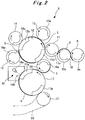
- the printing unit 3 includes: an impression cylinder 12 that transports a sheet 5 received through two transfer cylinders 10, 11 and wound on the circumferential surface of the impression cylinder 12; a seal cylinder 13 that prints the seal onto the sheet 5 transported by this impression cylinder 12; first and second number cylinders 14, 15 that prints numbers onto the sheet 5 transported by the impression cylinder 12; a transfer cylinder 16 that is provided in contact with the impression cylinder 12 and transports the sheet received from the impression cylinder 12; a checking cylinder 17 that transports the sheet 5 received from this transfer cylinder 16 and wound on the circumferential surface of the checking cylinder 17; and a checking device 18 as a printing-quality checking device that checks the quality of the seal and numbers printed on the sheet 5 wound and transported on the circumferential surface of this checking cylinder 17.
- the circumferential surfaces of the transfer cylinders 9, 10, 11 are provided with gaps 9a, 10a, 11a, the gaps in the adjacent cylinders facing each other.
- the diameter of the impression cylinder 12 and the checking cylinder 17 is twice as large as the diameter of the seal cylinder 13 and the first and second number cylinders 14, 15.
- the circumferential surface of the impression cylinder 12 is provided with a pair of gaps 12a, 12a shifted from each in phase by 180° in the circumferential direction.
- the gap 11a in the transfer cylinder 11 faces these gaps 12a, 12a.
- the circumferential surfaces of the seal cylinder 13, the first and second number cylinders 14, 15, and the transfer cylinder 16 are provided with gaps 13a, 14a, 15a, 16a that face the gaps 12a, 12a.
- gripper devices not illustrated are provided as sheet holding devices that hold the forward edge (leading edge) of a sheet 5.
- the first and second number cylinders 14, 15 are widely-known conventional cylinders including a plurality of numbering units in the circumferential direction on a rotation shaft not illustrated with a mount ring therebetween.
- the number cylinders 14, 15 are driven by a number shift mechanism provided at an end of the shaft, and the numbers are incremented each time the number cylinders 14, 15 rotate 360°.
- the circumferential surface of the checking cylinder 17 is provided with a pair of gaps 17a, 17a that are shifted from each other in phase by 180° in the circumferential direction and face the gap 16a in the transfer cylinder 16.
- the circumferential surface of the checking cylinder 17 excluding the gaps 17a is provided with many suction holes (not illustrated), and a sheet 5 passed from the transfer cylinder 16 is transported in a sucked state on this circumferential surface of the checking cylinder 17.
- gripper devices not illustrated are provided as sheet holding devices that hold the forward edge (leading edge) of a sheet 5.
- the checking device 18 includes a checking camera 18a that images a sheet 5 wound on and transported by the checking cylinder 17, and a light source 18h that applies light toward the checking cylinder 17 (the sheet 5 imaged by the checking camera 18a) . Based on the image captured by the checking camera 18a, the checking device 18 checks the condition of printing of the seal and numbers printed on the sheet 5 transported by the checking cylinder 17 and checks whether the printed numbers match the numbers that are supposed to be printed.
- reference numeral 19 denotes an inker that includes an ink fountain and a group of many rollers and supplies ink to the seal cylinder 13.
- Reference numerals 20a, 20b denote inkers including ink fountains and groups of many rollers and supply ink to the first and second number cylinders 14, 15, respectively.
- Reference numeral 21 denotes a delivery cylinder in contact with the checking cylinder 17.
- a pair of left and right delivery chains 23 are laid in a tensioned state between sprockets (not illustrated) provided coaxially with this delivery cylinder 21 and sprockets 22 provided at the end of the delivery unit 4.
- Delivery grippers 24 as a plurality of gripper bars are provided on gripper shafts supported at certain intervals between these left and right delivery chains 23. These delivery grippers 24 receive a sheet 5 gripped by a gripper device of the checking cylinder 17 in cooperation with the delivery cylinder 21 and transports the sheet 5 to the delivery unit 4 as the delivery chains 23 is run.
- Reference numeral 25A denotes a first discharge-cam moving device provided above a first delivery pile 31, which is a first discharge pile, and includes a first delivery cam 27A as a first discharge cam supported on left and right delivery frames (not illustrated) so as to be pivotable about a shaft 26A, and an air cylinder 28A that moves this first delivery cam 27A to an advance position to which the first delivery cam 27A is caused to advance to be in the travel path for the delivery grippers 24 (the travel path for cam followers of the delivery grippers 24) and to a retreat position to which the first delivery cam 27A is caused to retreat from the travel path.
- a first delivery cam 27A as a first discharge cam supported on left and right delivery frames (not illustrated) so as to be pivotable about a shaft 26A
- an air cylinder 28A that moves this first delivery cam 27A to an advance position to which the first delivery cam 27A is caused to advance to be in the travel path for the delivery grippers 24 (the travel path for cam followers of the delivery grippers 24) and to a retreat position to
- Reference numeral 25B denotes a second discharge-cam moving device provided downstream of the first discharge-cam moving device 25A in the direction of transport of sheets 5 and above a second delivery pile 32, which is a second discharge pile, and includes a second delivery cam 27B as a second discharge cam supported on left and right delivery frames (not illustrated) so as to be pivotable about a shaft 26B, and an air cylinder 28B that moves this second delivery cam 27B to an advance position to which the second delivery cam 27B is caused to advance to be in the travel path for the delivery grippers 24 (the travel path for the cam followers of the delivery grippers 24) and to a retreat position to which the second delivery cam 27B is caused to retreat from the travel path.
- a second delivery cam 27B as a second discharge cam supported on left and right delivery frames (not illustrated) so as to be pivotable about a shaft 26B
- an air cylinder 28B that moves this second delivery cam 27B to an advance position to which the second delivery cam 27B is caused to advance to be in the travel path for the delivery grippers
- Reference numeral 30 denotes a fixed cam provided downstream of the second delivery cam 27B in the direction of transport of sheets 5 and above a third delivery pile 33, which is a third discharge pile, and disposed so as to face the travel path for the delivery grippers 24 (the travel path for the cam followers of the delivery grippers 24). Then, with both the first and second delivery cams 27A, 27B caused to retreat from the travel path for the delivery grippers 24, some delivery grippers 24 pass under the first and second delivery cams 27A, 27B while keeping gripping their sheets 5, and their cam followers come into engagement with the fixed cam 30, so that the delivery grippers 24 release their grip and the sheets 5 are discharged onto the third delivery pile 33.
- the checking device 18 of the printing-quality checking device is configured to enable adjustment of the imaging angle of the checking camera 18a about a center P of the range for imaging of a sheet 5 by the imaging camera 18a (hereinafter, the detection point) with respect to a normal line connecting the center of the checking cylinder 17 and the detection point P, while keeping the checking camera 18a in focus at the detection point P.
- the detection point a center P of the range for imaging of a sheet 5 by the imaging camera 18a
- the detection point a normal line connecting the center of the checking cylinder 17 and the detection point P
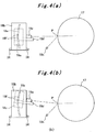
- the checking camera 18a is supported on a support plate 18d.
- Guide members 18c are fixed to the opposite sides of the support plate 18d in the axial direction of the checking cylinder 17, respectively, and the two guide members 18c are swingably supported on guide plates 18b, respectively.
- two guide pins 18f are fixed to each of the two guide members 18c on the same arc centered at the detection point P, and these guide pins 18f project toward the respective guide plates 18b.
- the two guide plates 18b are provided with arc-shaped guide holes 18e centered at the detection point P.
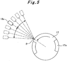
- the guide pins 18f By engaging the guide pins 18f with the guide holes 18e and moving the guide members 18c to slide the guide pins 18f along the guide holes 18e, it is possible to swing the checking camera 18a along the arc centered at the detection point P with the support plate 18d while keeping the checking camera 18a in focus at the detection point P, as illustrated in Fig. 5 .
- the guide plates 18b are fixed to two frames 34 extending in the axial direction of the checking cylinder 17. Also, the light source 18h is installed so as to apply light to the detection point P.
- the data of an image captured by the checking camera 18a is inputted into a printing-quality checking unit 18g and compared with the data of a reference image by the printing-quality checking unit 18g to check the printing quality.
- reference numeral 36 denotes a control device.
- reference numeral 37 denotes a camera-adjustment switch operated when the position of the checking camera 18a is adjusted.
- Reference numeral 38 denotes a camera-adjustment end switch operated when the positional adjustment of the checking camera 18a is ended.
- the control device 36 Upon input of an ON signal from the camera-adjustment switch 37, the control device 36 outputs a feed start command to the feeder 2, outputs a printing start command to the printing unit 3, outputs an imaging command to the checking camera 18a, and outputs an image display command to a display unit 40. Consequently, number printing is performed on a sheet 5, the checking camera 18a images the sheet 5, and the display unit 40 displays the image captured by the checking camera 18a.
- control device 36 upon input of an ON signal from the camera-adjustment end switch 38, the control device 36 outputs a feed end command to the feeder 2, outputs a printing end command to the printing unit 3, and outputs an imaging end command to the checking camera 18a. Consequently, the number printing on sheets 5 and the imaging of sheets 5 by the checking camera 18a end.
- each sheet 5 is a printed product
- the checking camera 18a is imaging means
- the light source 18h is a light source
- the printing-quality checking unit 18g is printing-quality checking means
- the support plate 18d, the guide members 18c, and the guide pins 18f are a support member
- the guide plates 18b and the guide holes 18e are a guiding member.
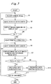
- the guide members 18c are slid relative to the guide plates 18b with the guide pins 18f engaged with the guide holes 18e to adjust the position (imaging angle) of the checking camera 18a (step S1). Then, the numbers printed on a sheet 5 are imaged with the checking camera 18a (step S2) . The image captured by the checking camera 18a is displayed on the display unit 40 (step S3).
- step S4 whether or not the numbers are readable is determined from the image displayed on the display unit 40 (step S4) . If the image displayed on the display unit 40 is in a state where the light from the specular reflection member 5a is excessively intense and makes the diffuse-reflected patterns (numbers) unreadable, as illustrated in Fig. 8B , in step S4 (NO), the processing returns to the process in step S1. On the other hand, if the image displayed on the display unit 40 is in a state where the ratio between the intensity of light from the specular reflection member 5a and the intensity of light from the diffuse-reflected patterns (numbers) is well balanced and the numbers are readable, as illustrated in Fig. 8A , (YES), a printing operation is started (step S5).
- step S5 If a printing operation is started in step S5, the numbers are imaged with the checking camera 18a (step S6). The image data of the imaged numbers and the reference image data are compared with each other (step S7) to determine whether or not the printing quality of the seal and numbers printed on the sheet 5 is good, and whether or not the printed numbers match the numbers that are supposed to be printed (step S8). If the seal and numbers are determined to be normal (PASS), the sheet 5 is discharged onto a good paper pile (step S9) . If the seal and/or numbers are determined to be abnormal (FAIL), the sheet 5 is discharged onto a wasted paper pile (step S10).
- PASS normal
- FAIL If the seal and/or numbers are determined to be abnormal (FAIL), the sheet 5 is discharged onto a wasted paper pile (step S10).
- step S6 The above-described processes in and after step S6 are repeated until the printing operation ends (step S11).
- the printing-quality checking device allows adjustment of the position of the checking camera 18a relative to the normal line connecting the center of the checking cylinder 17, which supports a sheet 5, and the detection point P for imaging of the sheet 5 by the checking camera 18a, along an arc centered at the detection point P (adjustment of the imaging angle of the checking camera 18a while keeping it in focus at the detection point P).
- the sheet 5 with the specular reflection member 5a provided thereto can be reliably checked for the printing quality of the patterns (numbers) printed on this specular reflection member 5a.
- the single numbering and imprinting machine 1 is configured to include both the seal cylinder 13 for printing a seal and the number cylinders 14, 15 for printing numbers in this embodiment, a configuration with only a seal cylinder or only a number cylinder may also be employed.
- the checking cylinder 17 is a double-size cylinder, it may be a single-size cylinder or a triple-size cylinder in accordance with the performance of the checking camera 18a.
- the means for adjusting the position of the checking camera 18a is not limited to the above example but may be any means as long as it can adjust the position of the checking camera 18a along an arc centered at the detection point P.
- a second embodiment of the printing-quality checking device according to the present invention will be described based on Figs. 9 to 11 .
- the printing-quality checking device is configured such that the position of the checking camera 18a is fixed and the position of the light source 18h is adjustable.
- the checking device 18 is configured such that the light application angle to the detection point P is changed by adjusting the position of the light source 18h to thereby enable adjustment of the ratio between the intensity of specularly reflected light from the specular reflection member 5a of a sheet 5 and the intensity of diffuse-reflected light from the pattern portions (numbers in this embodiment) printed on the specular reflection member 5a, which are imaged by the checking camera 18a. Note that the position of the checking camera 18a is fixed.
- the light source 18h is supported on a support plate 18k.
- Two guide members 18j are fixed to the opposite sides of the support plate 18k in the axial direction of the checking cylinder 17, respectively, and the two guide members 18j are swingably supported on two guide plates 18i, respectively.
- two guide pins 18m are fixed to each of the two guide members 18j on the same arc centered at the detection point P, and these guide pins 18m project toward the respective guide plates 18i.
- the two guide plates 18i are provided with arc-shaped guide holes 181 centered at the detection point P.
- the guide pins 18m By engaging the guide pins 18m with the guide holes 181 and moving the guide members 18j to slide the guide pins 18m along the guide holes 181, it is possible to swing the light source 18h along the arc centered at the detection point P with the support plate 18k while keeping the light application direction of the light source 18h pointing at the detection point P.
- guide plates 18i are fixed between two frames 35 extending in the axial direction of the checking cylinder 17.
- each sheet 5 is a printed product
- the checking camera 18a is imaging means
- the light source 18h is a light source
- the printing-quality checking unit 18g is printing-quality checking means
- the support plate 18k, the guide members 18j, and the guide pins 18m are a support member
- the guide plates 18i and the guide holes 181 are a guiding member.
- the guide members 18j are slid relative to the guide plates 18i with the guide pins 18m engaged with the guide holes 181 to adjust the position (light application angle) of the light source 18h (step S21). Then, the numbers printed on a sheet 5 are imaged with the checking camera 18a (step S22) . The image captured by the checking camera 18a is displayed on the display unit 40 (step S23).
- step S24 whether or not the numbers are readable is determined from the image displayed on the display unit 40 . If the image displayed on the display unit 40 is in a state where the light from the specular reflection member 5a is excessively intense and makes the diffuse-reflected patterns (numbers) unreadable, as illustrated in Fig. 8B , in step S24 (NO), the processing returns to the process in step S21. On the other hand, if the image displayed on the display unit 40 is in a state where the ratio between the intensity of light from the specular reflection member 5a and the intensity of light from the diffuse-reflected patterns (numbers) is well balanced and the numbers are readable, as illustrated in Fig. 8A , (YES), a printing operation is started (step S25).
- step S25 the numbers are imaged with the checking camera 18a (step S26).
- step S27 The image data of the imaged numbers and the reference image data are compared with each other (step S27) to determine whether or not the printing quality of the seal and numbers printed on the sheet 5 is good, and whether or not the printed numbers match the numbers that are supposed to be printed (step S28). If the seal and numbers are determined to be normal (PASS), the sheet 5 is discharged onto a good paper pile (step S29) . If the seal and/or numbers are determined to be abnormal (FAIL), the sheet 5 is discharged onto a wasted paper pile (step S30).
- step S26 The above-described processes in and after step S26 are repeated until the printing operation ends (step S31).
- the printing-quality checking device allows adjustment of the position of the light source 18h along an arc centered at the detection point P (adjustment of the light application angle of the light source 18h about the detection point P while keeping its light application direction pointing at the detection point P) .
- the sheet 5 with the specular reflection member 5a provided thereto can be reliably checked for the printing quality of the patterns (numbers) printed on this specular reflection member 5a.
- the positions of both the checking camera 18a and the light source 18h may be adjusted to adjust the ratio between the intensity of specularly reflected light from the specular reflection member 5a of a sheet 5 and the intensity of diffuse-reflected light from the pattern portions (numbers in this embodiment) printed on the specular reflection member 5a, which are imaged by the checking camera 18a.
- the present invention is applicable to a printing-quality checking device for checking the printing quality of a pattern printed on a specular reflection member provided to a printed product.
Landscapes
- Engineering & Computer Science (AREA)
- Immunology (AREA)
- Health & Medical Sciences (AREA)
- Chemical & Material Sciences (AREA)
- Analytical Chemistry (AREA)
- Biochemistry (AREA)
- General Health & Medical Sciences (AREA)
- Life Sciences & Earth Sciences (AREA)
- General Physics & Mathematics (AREA)
- Pathology (AREA)
- Physics & Mathematics (AREA)
- Quality & Reliability (AREA)
- Mechanical Engineering (AREA)
- Inking, Control Or Cleaning Of Printing Machines (AREA)
- Rotary Presses (AREA)
- Investigating Or Analysing Materials By Optical Means (AREA)
- Investigating Materials By The Use Of Optical Means Adapted For Particular Applications (AREA)
Abstract
Description
- The present invention relates to a printing-quality checking device for checking the printing quality of a pattern printed on a specular reflection member provided to a printed product.
- Printing presses including a checking device for checking a pattern printed on a printed product have heretofore been known (see
Patent Document 1 listed below, for example). - Patent Document 1: Japanese Patent Application Publication No.
2012-135885 - Here, for printed securities products such as bank notes, a specular reflection member such as a hologram or a security thread is often added to or processed in their surfaces as a protection against counterfeiting. When patterns are printed on the surface of such a printed securities product where a hologram, a security thread, or the like has been added to or processed in advance, patterns are printed also on the specular reflection member in some cases.
- A problem with these cases is that, when a checking device checks the printing quality of the printed securities product, the specularly reflected light from the hologram or security thread portion is so intense that the diffuse-reflected light from the pattern portion printed thereon is unreadable and it is impossible to determine whether the patterns are printed correctly.
- The present invention has been made to solve such a problem, and an object thereof is to provide a printing-quality checking device capable of accurately checking the quality of a pattern printed on the surface of a specular reflection member.
- A printing-quality checking device according to a first aspect of the invention for solving the above problem is a printing-quality checking device provided to a printing press including a printing unit that performs printing on a specular reflection member provided to a printed product, the printing-quality checking device including:
- a light source that applies light to the printed product;
- an imaging device that images a pattern printed on the printed product; and
- a printing-quality checking unit that checks quality of the pattern printed by the printing unit, based on image data captured by the imaging device,
- the printing-quality checking device characterized in that
- the imaging device or the light source is supported to be movable along an arc centered at a detection point on the printed product imaged by the imaging device.
- A printing-quality checking device according to a second aspect of the invention for solving the above problem is characterized in that the printing-quality checking device further comprises:
- a support member that supports the imaging device or the light source; and
- a guiding member that guides the support member along the arc.
- A printing-quality checking device according to a third aspect of the invention for solving the above problem is characterized in that
the support member includes - a support plate which supports the imaging device or the light source, and
- guide members which are fixed to axially opposite sides of the support plate and to each of which two guide pins are fixed on a same arc centered at the detection point,
- According to the present invention, it is possible to accurately check the quality of a pattern printed on the surface of a specular reflection member.
-
-
Fig. 1 is a side view illustrating the entirety of a numbering and imprinting machine according to a first embodiment of the present invention. -
Fig. 2 is a side view illustrating a main part of the numbering and imprinting machine according to the first embodiment of the present invention. -
Fig. 3 is a top view illustrating a checking device according to the first embodiment of the present invention. -
Fig. 4 is a side view illustrating the checking device according to the first embodiment of the present invention. -
Fig. 5 is a diagram explaining movement of a checking camera according to the first embodiment of the present invention. -
Fig. 6 is a block diagram illustrating a control configuration for printing quality checking according to the first embodiment of the present invention. -
Fig. 7 is a flowchart explaining the procedure of the printing quality checking according to the first embodiment of the present invention. -
Fig. 8A is an explanatory view illustrating an example image captured by the checking camera according to the first embodiment of the present invention. -
Fig. 8B is an explanatory view illustrating another example image captured by the checking camera according to the first embodiment of the present invention. -
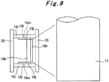
Fig. 9 is a top view illustrating a checking device according to a second embodiment of the present invention. -
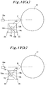
Fig. 10 is a side view illustrating the checking device according to the second embodiment of the present invention. -
Fig. 11 is a flowchart illustrating the procedure of printing quality checking according to the second embodiment of the present invention. - A first embodiment of a printing-quality checking device according to the present invention will now be described based on
Figs. 1 to 7 andFigs. 8A and 8B . - A numbering and imprinting machine whose entirety is illustrated in
Fig. 1 withreference numeral 1 basically includes: afeeder 2 as a sheet feed unit that feedssheets 5 onto afeeder board 6 one by one; aprinting unit 3 that prints a seal and numbers ontofed sheets 5; and adelivery unit 4 as a sheet discharge unit that discharges printed sheets. - The
feeder 2 is provided with apile board 7 as a stack board on which to stackmany sheets 5 after addition or processing of aspecular reflection member 5a such as a hologram or a security thread by another printing press (seeFigs. 8A and 8B ; hereinafter, simply referred to as "specular reflection member 5a"). Thesheets 5 on thepile board 7 are sucked and fed onto thefeeder board 6 one by one by a suction device not illustrated, and fed to theprinting unit 3 by a swingarm shaft pregripper 8 through atransfer cylinder 9. - The
printing unit 3 includes: animpression cylinder 12 that transports asheet 5 received through twotransfer cylinders impression cylinder 12; aseal cylinder 13 that prints the seal onto thesheet 5 transported by thisimpression cylinder 12; first andsecond number cylinders sheet 5 transported by theimpression cylinder 12; atransfer cylinder 16 that is provided in contact with theimpression cylinder 12 and transports the sheet received from theimpression cylinder 12; a checkingcylinder 17 that transports thesheet 5 received from thistransfer cylinder 16 and wound on the circumferential surface of the checkingcylinder 17; and achecking device 18 as a printing-quality checking device that checks the quality of the seal and numbers printed on thesheet 5 wound and transported on the circumferential surface of this checkingcylinder 17. - As illustrated in
Fig. 2 , the circumferential surfaces of thetransfer cylinders gaps impression cylinder 12 and the checkingcylinder 17 is twice as large as the diameter of theseal cylinder 13 and the first andsecond number cylinders impression cylinder 12 is provided with a pair ofgaps gap 11a in thetransfer cylinder 11 faces thesegaps seal cylinder 13, the first andsecond number cylinders transfer cylinder 16 are provided withgaps gaps gaps transfer cylinders impression cylinder 12, and thetransfer cylinder 16, gripper devices not illustrated are provided as sheet holding devices that hold the forward edge (leading edge) of asheet 5. - The first and
second number cylinders number cylinders number cylinders cylinder 17 is provided with a pair ofgaps gap 16a in thetransfer cylinder 16. Also, the circumferential surface of the checkingcylinder 17 excluding thegaps 17a is provided with many suction holes (not illustrated), and asheet 5 passed from thetransfer cylinder 16 is transported in a sucked state on this circumferential surface of the checkingcylinder 17. In thegaps cylinder 17 too, gripper devices not illustrated are provided as sheet holding devices that hold the forward edge (leading edge) of asheet 5. - The
checking device 18 includes a checkingcamera 18a that images asheet 5 wound on and transported by the checkingcylinder 17, and alight source 18h that applies light toward the checking cylinder 17 (thesheet 5 imaged by the checkingcamera 18a) . Based on the image captured by the checkingcamera 18a, thechecking device 18 checks the condition of printing of the seal and numbers printed on thesheet 5 transported by the checkingcylinder 17 and checks whether the printed numbers match the numbers that are supposed to be printed. - In
Fig. 1 ,reference numeral 19 denotes an inker that includes an ink fountain and a group of many rollers and supplies ink to theseal cylinder 13.Reference numerals second number cylinders -
Reference numeral 21 denotes a delivery cylinder in contact with the checkingcylinder 17. A pair of left andright delivery chains 23 are laid in a tensioned state between sprockets (not illustrated) provided coaxially with thisdelivery cylinder 21 andsprockets 22 provided at the end of thedelivery unit 4.Delivery grippers 24 as a plurality of gripper bars are provided on gripper shafts supported at certain intervals between these left andright delivery chains 23. Thesedelivery grippers 24 receive asheet 5 gripped by a gripper device of the checkingcylinder 17 in cooperation with thedelivery cylinder 21 and transports thesheet 5 to thedelivery unit 4 as thedelivery chains 23 is run. -
Reference numeral 25A denotes a first discharge-cam moving device provided above afirst delivery pile 31, which is a first discharge pile, and includes afirst delivery cam 27A as a first discharge cam supported on left and right delivery frames (not illustrated) so as to be pivotable about ashaft 26A, and anair cylinder 28A that moves thisfirst delivery cam 27A to an advance position to which thefirst delivery cam 27A is caused to advance to be in the travel path for the delivery grippers 24 (the travel path for cam followers of the delivery grippers 24) and to a retreat position to which thefirst delivery cam 27A is caused to retreat from the travel path. In this configuration, with theair cylinder 28A driven to cause thefirst delivery cam 27A to advance into the travel path for thedelivery grippers 24, the cam followers (not illustrated) of somedelivery grippers 24 come into engagement with thefirst delivery cam 27A, so that thedelivery grippers 24 release their grip and thesheets 5 are discharged onto thefirst delivery pile 31. On the other hand, with theair cylinder 28A driven to cause thefirst delivery cam 27A to retreat from the travel path for thedelivery grippers 24, the cam followers (not illustrated) of thedelivery grippers 24 do not come into engagement with thefirst delivery cam 27A, so that thedelivery grippers 24 pass below thefirst delivery cam 27A while keeping gripping theirsheets 5. -
Reference numeral 25B denotes a second discharge-cam moving device provided downstream of the first discharge-cam moving device 25A in the direction of transport ofsheets 5 and above asecond delivery pile 32, which is a second discharge pile, and includes asecond delivery cam 27B as a second discharge cam supported on left and right delivery frames (not illustrated) so as to be pivotable about ashaft 26B, and anair cylinder 28B that moves thissecond delivery cam 27B to an advance position to which thesecond delivery cam 27B is caused to advance to be in the travel path for the delivery grippers 24 (the travel path for the cam followers of the delivery grippers 24) and to a retreat position to which thesecond delivery cam 27B is caused to retreat from the travel path. In this configuration, with theair cylinder 28B driven to cause thesecond delivery cam 27B to advance into the travel path for thedelivery grippers 24, the cam followers (not illustrated) of somedelivery grippers 24 come into engagement thesecond delivery cam 27B, so that thedelivery grippers 24 release their grip and thesheets 5 are discharged onto thesecond delivery pile 32. On the other hand, with theair cylinder 28B driven to cause thesecond delivery cam 27B to retreat from the travel path for thedelivery grippers 24, the cam followers (not illustrated) of thedelivery grippers 24 do not come into engagement with thesecond delivery cam 27B, so that thedelivery grippers 24 pass below thesecond delivery cam 27B while keeping gripping theirsheets 5. -
Reference numeral 30 denotes a fixed cam provided downstream of thesecond delivery cam 27B in the direction of transport ofsheets 5 and above athird delivery pile 33, which is a third discharge pile, and disposed so as to face the travel path for the delivery grippers 24 (the travel path for the cam followers of the delivery grippers 24). Then, with both the first andsecond delivery cams delivery grippers 24, somedelivery grippers 24 pass under the first andsecond delivery cams sheets 5, and their cam followers come into engagement with the fixedcam 30, so that thedelivery grippers 24 release their grip and thesheets 5 are discharged onto thethird delivery pile 33. - Here, the checking
device 18 of the printing-quality checking device according to this embodiment is configured to enable adjustment of the imaging angle of the checkingcamera 18a about a center P of the range for imaging of asheet 5 by theimaging camera 18a (hereinafter, the detection point) with respect to a normal line connecting the center of the checkingcylinder 17 and the detection point P, while keeping the checkingcamera 18a in focus at the detection point P. In this way, it is possible to adjust the ratio between the intensity of specularly reflected light from thespecular reflection member 5a and the intensity of diffuse-reflected light from the pattern portion (numbers in this embodiment) printed on thespecular reflection member 5a in the image captured by the checkingcamera 18a. - Details of the
checking device 18 in this embodiment will now be described usingFigs. 3 to 5 . - As illustrated in
Figs. 3 and4 , in thechecking device 18 in this embodiment, the checkingcamera 18a is supported on asupport plate 18d.Guide members 18c are fixed to the opposite sides of thesupport plate 18d in the axial direction of the checkingcylinder 17, respectively, and the twoguide members 18c are swingably supported onguide plates 18b, respectively. - Specifically, two
guide pins 18f are fixed to each of the twoguide members 18c on the same arc centered at the detection point P, and theseguide pins 18f project toward therespective guide plates 18b. - Moreover, the two
guide plates 18b are provided with arc-shapedguide holes 18e centered at the detection point P. By engaging theguide pins 18f with the guide holes 18e and moving theguide members 18c to slide the guide pins 18f along theguide holes 18e, it is possible to swing the checkingcamera 18a along the arc centered at the detection point P with thesupport plate 18d while keeping the checkingcamera 18a in focus at the detection point P, as illustrated inFig. 5 . - Note that the
guide plates 18b are fixed to twoframes 34 extending in the axial direction of the checkingcylinder 17. Also, thelight source 18h is installed so as to apply light to the detection point P. - The data of an image captured by the checking
camera 18a is inputted into a printing-quality checking unit 18g and compared with the data of a reference image by the printing-quality checking unit 18g to check the printing quality. - Next, camera-angle adjustment control in this embodiment will be described using
Fig. 6 . InFig. 6 ,reference numeral 36 denotes a control device. Also,reference numeral 37 denotes a camera-adjustment switch operated when the position of the checkingcamera 18a is adjusted.Reference numeral 38 denotes a camera-adjustment end switch operated when the positional adjustment of the checkingcamera 18a is ended. - Upon input of an ON signal from the camera-
adjustment switch 37, thecontrol device 36 outputs a feed start command to thefeeder 2, outputs a printing start command to theprinting unit 3, outputs an imaging command to the checkingcamera 18a, and outputs an image display command to adisplay unit 40. Consequently, number printing is performed on asheet 5, the checkingcamera 18a images thesheet 5, and thedisplay unit 40 displays the image captured by the checkingcamera 18a. - Also, upon input of an ON signal from the camera-
adjustment end switch 38, thecontrol device 36 outputs a feed end command to thefeeder 2, outputs a printing end command to theprinting unit 3, and outputs an imaging end command to the checkingcamera 18a. Consequently, the number printing onsheets 5 and the imaging ofsheets 5 by the checkingcamera 18a end. - In this embodiment as described above, each
sheet 5 is a printed product, the checkingcamera 18a is imaging means, thelight source 18h is a light source, the printing-quality checking unit 18g is printing-quality checking means, thesupport plate 18d, theguide members 18c, and the guide pins 18f are a support member, and theguide plates 18b and theguide holes 18e are a guiding member. - The procedure of the printing quality checking by the
control device 36 will now be described briefly by usingFig. 7 . - As illustrated in
Fig. 7 , theguide members 18c are slid relative to theguide plates 18b with the guide pins 18f engaged with the guide holes 18e to adjust the position (imaging angle) of the checkingcamera 18a (step S1). Then, the numbers printed on asheet 5 are imaged with the checkingcamera 18a (step S2) . The image captured by the checkingcamera 18a is displayed on the display unit 40 (step S3). - Then, whether or not the numbers are readable is determined from the image displayed on the display unit 40 (step S4) . If the image displayed on the
display unit 40 is in a state where the light from thespecular reflection member 5a is excessively intense and makes the diffuse-reflected patterns (numbers) unreadable, as illustrated inFig. 8B , in step S4 (NO), the processing returns to the process in step S1. On the other hand, if the image displayed on thedisplay unit 40 is in a state where the ratio between the intensity of light from thespecular reflection member 5a and the intensity of light from the diffuse-reflected patterns (numbers) is well balanced and the numbers are readable, as illustrated inFig. 8A , (YES), a printing operation is started (step S5). - If a printing operation is started in step S5, the numbers are imaged with the checking
camera 18a (step S6). The image data of the imaged numbers and the reference image data are compared with each other (step S7) to determine whether or not the printing quality of the seal and numbers printed on thesheet 5 is good, and whether or not the printed numbers match the numbers that are supposed to be printed (step S8). If the seal and numbers are determined to be normal (PASS), thesheet 5 is discharged onto a good paper pile (step S9) . If the seal and/or numbers are determined to be abnormal (FAIL), thesheet 5 is discharged onto a wasted paper pile (step S10). - The above-described processes in and after step S6 are repeated until the printing operation ends (step S11).
- The printing-quality checking device according to this embodiment with the above configuration allows adjustment of the position of the checking
camera 18a relative to the normal line connecting the center of the checkingcylinder 17, which supports asheet 5, and the detection point P for imaging of thesheet 5 by the checkingcamera 18a, along an arc centered at the detection point P (adjustment of the imaging angle of the checkingcamera 18a while keeping it in focus at the detection point P). In this way, it is possible to adjust the ratio between the intensity of light from thespecular reflection member 5a and the intensity of light from the pattern (number) portions printed on thespecular reflection member 5a in the image captured by the checkingcamera 18a. Hence, thesheet 5 with thespecular reflection member 5a provided thereto can be reliably checked for the printing quality of the patterns (numbers) printed on thisspecular reflection member 5a. - Note that, although the single numbering and imprinting
machine 1 is configured to include both theseal cylinder 13 for printing a seal and thenumber cylinders cylinder 17 is a double-size cylinder, it may be a single-size cylinder or a triple-size cylinder in accordance with the performance of the checkingcamera 18a. - Also, although an example in which the position of the checking
camera 18a is adjusted using thesupport plate 18d and theguide plates 18b has been presented in this embodiment, the means for adjusting the position of the checkingcamera 18a is not limited to the above example but may be any means as long as it can adjust the position of the checkingcamera 18a along an arc centered at the detection point P. - A second embodiment of the printing-quality checking device according to the present invention will be described based on
Figs. 9 to 11 . - Unlike the printing-quality checking device according to the first embodiment, the printing-quality checking device according to this embodiment is configured such that the position of the checking
camera 18a is fixed and the position of thelight source 18h is adjustable. - Specifically, in this embodiment, the checking
device 18 is configured such that the light application angle to the detection point P is changed by adjusting the position of thelight source 18h to thereby enable adjustment of the ratio between the intensity of specularly reflected light from thespecular reflection member 5a of asheet 5 and the intensity of diffuse-reflected light from the pattern portions (numbers in this embodiment) printed on thespecular reflection member 5a, which are imaged by the checkingcamera 18a. Note that the position of the checkingcamera 18a is fixed. - The other features of the configuration are basically similar to those in the first embodiment. In the following, members that function similarly to members described in the first embodiment will be denoted by the same reference numerals, and repetitive description thereof will be omitted. The difference will be mainly described.
- As illustrated in
Figs. 9 and10 , in thechecking device 18 in this embodiment, thelight source 18h is supported on asupport plate 18k. Twoguide members 18j are fixed to the opposite sides of thesupport plate 18k in the axial direction of the checkingcylinder 17, respectively, and the twoguide members 18j are swingably supported on twoguide plates 18i, respectively. - Specifically, two
guide pins 18m are fixed to each of the twoguide members 18j on the same arc centered at the detection point P, and these guide pins 18m project toward therespective guide plates 18i. - Moreover, the two
guide plates 18i are provided with arc-shaped guide holes 181 centered at the detection point P. By engaging the guide pins 18m with the guide holes 181 and moving theguide members 18j to slide the guide pins 18m along the guide holes 181, it is possible to swing thelight source 18h along the arc centered at the detection point P with thesupport plate 18k while keeping the light application direction of thelight source 18h pointing at the detection point P. - Note that the
guide plates 18i are fixed between twoframes 35 extending in the axial direction of the checkingcylinder 17. - In this embodiment as described above, each
sheet 5 is a printed product, the checkingcamera 18a is imaging means, thelight source 18h is a light source, the printing-quality checking unit 18g is printing-quality checking means, thesupport plate 18k, theguide members 18j, and the guide pins 18m are a support member, and theguide plates 18i and the guide holes 181 are a guiding member. - The procedure of the printing quality checking by the
control device 36 will now be described briefly by usingFig. 11 . - As illustrated in
Fig. 11 , theguide members 18j are slid relative to theguide plates 18i with the guide pins 18m engaged with the guide holes 181 to adjust the position (light application angle) of thelight source 18h (step S21). Then, the numbers printed on asheet 5 are imaged with the checkingcamera 18a (step S22) . The image captured by the checkingcamera 18a is displayed on the display unit 40 (step S23). - Then, whether or not the numbers are readable is determined from the image displayed on the display unit 40 (step S24) . If the image displayed on the
display unit 40 is in a state where the light from thespecular reflection member 5a is excessively intense and makes the diffuse-reflected patterns (numbers) unreadable, as illustrated inFig. 8B , in step S24 (NO), the processing returns to the process in step S21. On the other hand, if the image displayed on thedisplay unit 40 is in a state where the ratio between the intensity of light from thespecular reflection member 5a and the intensity of light from the diffuse-reflected patterns (numbers) is well balanced and the numbers are readable, as illustrated inFig. 8A , (YES), a printing operation is started (step S25). - If a printing operation is started in step S25, the numbers are imaged with the checking
camera 18a (step S26). The image data of the imaged numbers and the reference image data are compared with each other (step S27) to determine whether or not the printing quality of the seal and numbers printed on thesheet 5 is good, and whether or not the printed numbers match the numbers that are supposed to be printed (step S28). If the seal and numbers are determined to be normal (PASS), thesheet 5 is discharged onto a good paper pile (step S29) . If the seal and/or numbers are determined to be abnormal (FAIL), thesheet 5 is discharged onto a wasted paper pile (step S30). - The above-described processes in and after step S26 are repeated until the printing operation ends (step S31).
- The printing-quality checking device according to this embodiment with the above configuration allows adjustment of the position of the
light source 18h along an arc centered at the detection point P (adjustment of the light application angle of thelight source 18h about the detection point P while keeping its light application direction pointing at the detection point P) . In this way, it is possible to adjust the ratio between the intensity of light from thespecular reflection member 5a and the intensity of light from the pattern (number) portions printed on thespecular reflection member 5a in the image captured by the checkingcamera 18a. Hence, thesheet 5 with thespecular reflection member 5a provided thereto can be reliably checked for the printing quality of the patterns (numbers) printed on thisspecular reflection member 5a. - In the above first and second embodiments, an example has been presented in which the position of either the checking
camera 18a or thelight source 18h is adjusted to adjust the ratio between the intensity of specularly reflected light from thespecular reflection member 5a of asheet 5 and the intensity of diffuse-reflected light from the pattern portions printed on thespecular reflection member 5a, which are imaged by the checkingcamera 18a. Note, however, that the present invention is not limited to the above embodiments. For example, the positions of both the checkingcamera 18a and thelight source 18h may be adjusted to adjust the ratio between the intensity of specularly reflected light from thespecular reflection member 5a of asheet 5 and the intensity of diffuse-reflected light from the pattern portions (numbers in this embodiment) printed on thespecular reflection member 5a, which are imaged by the checkingcamera 18a. - The present invention is applicable to a printing-quality checking device for checking the printing quality of a pattern printed on a specular reflection member provided to a printed product.
-
- 1
- numbering and imprinting machine
- 2
- feeder
- 3
- printing unit
- 4
- delivery unit
- 5
- sheet
- 5a
- specular reflection member
- 12
- impression cylinder
- 13
- seal cylinder
- 14
- first number cylinder
- 15
- second number cylinder
- 16
- transfer cylinder
- 17
- checking cylinder
- 18
- checking device
- 18a
- checking camera
- 18b
- guide plate
- 18c
- guide member
- 18d
- support plate
- 18e
- guide hole
- 18f
- guide pin
- 18g
- printing-quality checking unit
- 18h
- light source
- 18i
- guide plate
- 18j
- guide member
- 18k
- support plate
- 181
- guide hole
- 18m
- guide pin
- 23
- delivery chain
- 24
- delivery gripper
- 25A
- first discharge-cam moving device
- 25B
- second discharge-cam moving device
- 27A
- first delivery cam
- 27B
- second delivery cam
- 30
- fixed cam
- 31
- first delivery pile
- 32
- second delivery pile
- 33
- third delivery pile
- 34, 35
- frame
- 36
- control device
- 37
- camera-adjustment switch
- 38
- camera-adjustment end switch
- 40
- display unit
- P
- detection point
the imaging device or the light source moves along the arc centered at the detection point with the guide members and the support plate by allowing the guide pins to slide along the guide holes.
Claims (3)
- A printing-quality checking device provided to a printing press including a printing unit that performs printing on a specular reflection member provided to a printed product, the printing-quality checking device including:a light source that applies light to the printed product;an imaging device that images a pattern printed on the printed product; anda printing-quality checking unit that checks quality of the pattern printed by the printing unit, based on image data captured by the imaging device,the printing-quality checking device characterized in thatthe imaging device or the light source is supported to be movable along an arc centered at a detection point on the printed product imaged by the imaging device.
- The printing-quality checking device according to claim 1, characterized in that the printing-quality checking device further comprises:a support member that supports the imaging device or the light source; anda guiding member that guides the support member along the arc.
- The printing-press printing-quality checking device according to claim 2, characterized in that
the support member includesa support plate which supports the imaging device or the light source, andguide members which are fixed to axially opposite sides of the support plate and to each of which two guide pins are fixed on a same arc centered at the detection point,the guiding member includes two guide plates each of which includes an arc-shaped guide hole centered at the detection point, and
the imaging device or the light source moves along the arc centered at the detection point with the guide members and the support plate by allowing the guide pins to slide along the guide holes.
Applications Claiming Priority (2)
| Application Number | Priority Date | Filing Date | Title |
|---|---|---|---|
| JP2016138495A JP6842615B2 (en) | 2016-07-13 | 2016-07-13 | Print quality inspection equipment |
| PCT/JP2017/025344 WO2018012518A1 (en) | 2016-07-13 | 2017-07-12 | Print quality examination device |
Publications (2)
| Publication Number | Publication Date |
|---|---|
| EP3486086A1 true EP3486086A1 (en) | 2019-05-22 |
| EP3486086A4 EP3486086A4 (en) | 2020-03-25 |
Family
ID=60952078
Family Applications (1)
| Application Number | Title | Priority Date | Filing Date |
|---|---|---|---|
| EP17827645.7A Withdrawn EP3486086A4 (en) | 2016-07-13 | 2017-07-12 | DEVICE FOR EXAMINING THE PRINT QUALITY |
Country Status (5)
| Country | Link |
|---|---|
| US (1) | US10717269B2 (en) |
| EP (1) | EP3486086A4 (en) |
| JP (1) | JP6842615B2 (en) |
| CN (1) | CN109715405B (en) |
| WO (1) | WO2018012518A1 (en) |
Families Citing this family (7)
| Publication number | Priority date | Publication date | Assignee | Title |
|---|---|---|---|---|
| CN109366568A (en) * | 2018-11-30 | 2019-02-22 | 广州市普理司科技有限公司 | Multifunctional automatic quality inspection machine and its control method |
| CN109366567A (en) * | 2018-11-30 | 2019-02-22 | 广州市普理司科技有限公司 | Automatic product examine machine and its control method |
| CN109533538B (en) * | 2018-12-24 | 2024-06-25 | 广州市普理司科技有限公司 | Full-servo automatic inspection machine for picking and supplementing marks and control method thereof |
| EP4043217A1 (en) * | 2021-02-11 | 2022-08-17 | Heidelberger Druckmaschinen AG | Printing machine with a device for conveying printed material and with a camera |
| DE102023111581A1 (en) * | 2023-05-04 | 2024-11-07 | Koenig & Bauer Ag | Sheet handling machine with an inspection device and a pivoting lighting device |
| DE102023111583A1 (en) * | 2023-05-04 | 2024-11-07 | Koenig & Bauer Ag | sheet-fed printing press with a simultaneous printing inspection device |
| DE102023111582A1 (en) * | 2023-05-04 | 2024-11-07 | Koenig & Bauer Ag | Machine for handling sheets with an inspection device and a sensor adjustment path in the clear width |
Family Cites Families (20)
| Publication number | Priority date | Publication date | Assignee | Title |
|---|---|---|---|---|
| JPH10206338A (en) * | 1997-01-23 | 1998-08-07 | Advantest Corp | Foreign matter inspecting method and foreign matter inspecting device |
| JP2003251789A (en) * | 2001-12-27 | 2003-09-09 | Komori Corp | Printing quality inspection equipment for printing presses |
| AU2003295417A1 (en) * | 2002-11-08 | 2004-06-03 | Pressco Technology Inc. | System and method for associating container defect information to a specific path of manufacturing |
| CN100476413C (en) * | 2003-11-21 | 2009-04-08 | 中国印钞造币总公司 | Device and method used for detecting flake material fluorescent image printing quality |
| DE102004014532B3 (en) * | 2004-03-23 | 2005-03-03 | Koenig & Bauer Ag | Optical system for generating illuminated shape on moving material has delay time, switch-on duration sum less than exposure duration; material speed-dependent off time follows exposure period until next exposure period |
| DE202004011811U1 (en) * | 2004-07-28 | 2005-12-08 | Byk-Gardner Gmbh | Apparatus for the goniometric examination of optical surface properties |
| JP2006226857A (en) * | 2005-02-18 | 2006-08-31 | National Printing Bureau | Inspection method and inspection apparatus for printed matter |
| WO2007077592A1 (en) * | 2005-12-28 | 2007-07-12 | Dac Engineering Co., Ltd. | Printed matter inspection device |
| US7953560B2 (en) * | 2006-12-28 | 2011-05-31 | Lexmark International, Inc. | Method for measuring doctor blade geometric deviations |
| US7826048B2 (en) * | 2006-12-28 | 2010-11-02 | Lexmark International, Inc. | Apparatus for measuring doctor blade geometric deviations |
| DE102007007828B4 (en) * | 2007-02-16 | 2011-02-24 | Bst International Gmbh | Method and device for illuminating a printed image on a material web |
| JP5585228B2 (en) * | 2010-06-15 | 2014-09-10 | 株式会社リコー | Image inspection apparatus, image inspection method, and image forming apparatus |
| JP5798742B2 (en) | 2010-12-24 | 2015-10-21 | 株式会社小森コーポレーション | Number printing machine |
| JP2012240375A (en) * | 2011-05-23 | 2012-12-10 | Mitsubishi Heavy Industries Printing & Packaging Machinery Ltd | Color tone measuring device and method, color tone management device, and printer |
| SE537335C2 (en) | 2012-03-30 | 2015-04-07 | Lauri Eino William Faloon | Procedure for monitoring the accumulation of contaminants on a cloth |
| JP5887191B2 (en) * | 2012-04-19 | 2016-03-16 | 株式会社トーメーコーポレーション | Corneal imaging apparatus and cornea imaging method |
| JP5959001B2 (en) * | 2012-07-20 | 2016-08-02 | 株式会社小森コーポレーション | Sheet inspection equipment |
| US9804087B2 (en) * | 2013-06-11 | 2017-10-31 | Scattermaster, Llc | Hemispherical scanning optical scatterometer |
| JP2015104832A (en) * | 2013-11-29 | 2015-06-08 | 株式会社小森コーポレーション | Inspection device for sheet-like object |
| CN203798742U (en) * | 2014-04-21 | 2014-08-27 | 玉田县大恒印刷机械有限公司 | Printed matter back face quality detection mechanism and product detecting machine |
-
2016
- 2016-07-13 JP JP2016138495A patent/JP6842615B2/en not_active Expired - Fee Related
-
2017
- 2017-07-12 CN CN201780039214.1A patent/CN109715405B/en not_active Expired - Fee Related
- 2017-07-12 EP EP17827645.7A patent/EP3486086A4/en not_active Withdrawn
- 2017-07-12 WO PCT/JP2017/025344 patent/WO2018012518A1/en not_active Ceased
- 2017-07-12 US US16/315,446 patent/US10717269B2/en not_active Expired - Fee Related
Also Published As
| Publication number | Publication date |
|---|---|
| WO2018012518A1 (en) | 2018-01-18 |
| EP3486086A4 (en) | 2020-03-25 |
| CN109715405A (en) | 2019-05-03 |
| JP6842615B2 (en) | 2021-03-17 |
| US20190224963A1 (en) | 2019-07-25 |
| JP2018008413A (en) | 2018-01-18 |
| US10717269B2 (en) | 2020-07-21 |
| CN109715405B (en) | 2021-02-09 |
Similar Documents
| Publication | Publication Date | Title |
|---|---|---|
| US10717269B2 (en) | Print quality examination device | |
| RU2413618C2 (en) | Control system for sheet printing machine for double-sided printing | |
| CN102627025B (en) | For printing the offset press of security | |
| KR102121366B1 (en) | Simultaneous double-sided printing of sheets, in particular sheet-fed printing machines | |
| US9170206B2 (en) | Inspection apparatus for sheet | |
| EP2910374B1 (en) | Combination printer | |
| EP2468506B1 (en) | Identification mark printing machine | |
| US10308012B2 (en) | Method for checking the maintenance of register of printed images to be printed on two opposite sides of a printing material | |
| EP3406447A1 (en) | Printer | |
| CN120897849A (en) | A machine for handling single sheets of paper, equipped with an inspection device and a pivotable lighting device. | |
| US20130104758A1 (en) | Intaglio printing press | |
| EP3527375B1 (en) | Processing device | |
| EP3466852B1 (en) | Printer | |
| CN120897848B (en) | A machine for handling single sheets of paper, equipped with an inspection device and sensors within the clear width for adjusting the path. | |
| JP6814562B2 (en) | Combination printing machine | |
| CN120916899B (en) | Sheet-fed printing press with simultaneous printing inspection device | |
| JP2005212142A (en) | Printer | |
| JP2006346992A (en) | Printing device | |
| JP2006346992A5 (en) | ||
| US20190105935A1 (en) | Double-sided varnishing apparatus |
Legal Events
| Date | Code | Title | Description |
|---|---|---|---|
| STAA | Information on the status of an ep patent application or granted ep patent |
Free format text: STATUS: THE INTERNATIONAL PUBLICATION HAS BEEN MADE |
|
| PUAI | Public reference made under article 153(3) epc to a published international application that has entered the european phase |
Free format text: ORIGINAL CODE: 0009012 |
|
| STAA | Information on the status of an ep patent application or granted ep patent |
Free format text: STATUS: REQUEST FOR EXAMINATION WAS MADE |
|
| 17P | Request for examination filed |
Effective date: 20190107 |
|
| AK | Designated contracting states |
Kind code of ref document: A1 Designated state(s): AL AT BE BG CH CY CZ DE DK EE ES FI FR GB GR HR HU IE IS IT LI LT LU LV MC MK MT NL NO PL PT RO RS SE SI SK SM TR |
|
| AX | Request for extension of the european patent |
Extension state: BA ME |
|
| DAV | Request for validation of the european patent (deleted) | ||
| DAX | Request for extension of the european patent (deleted) | ||
| A4 | Supplementary search report drawn up and despatched |
Effective date: 20200224 |
|
| RIC1 | Information provided on ipc code assigned before grant |
Ipc: G01N 21/88 20060101ALI20200218BHEP Ipc: B41M 3/14 20060101ALI20200218BHEP Ipc: B41F 13/00 20060101ALI20200218BHEP Ipc: B41F 33/00 20060101AFI20200218BHEP |
|
| STAA | Information on the status of an ep patent application or granted ep patent |
Free format text: STATUS: EXAMINATION IS IN PROGRESS |
|
| 17Q | First examination report despatched |
Effective date: 20220126 |
|
| RAP1 | Party data changed (applicant data changed or rights of an application transferred) |
Owner name: KOMORI CORPORATION |
|
| STAA | Information on the status of an ep patent application or granted ep patent |
Free format text: STATUS: THE APPLICATION IS DEEMED TO BE WITHDRAWN |
|
| 18D | Application deemed to be withdrawn |
Effective date: 20240806 |