EP3485983A1 - Outil de lissage d'un cordon d'etancheite par raclage et/ou aspiration, muni d'une cale facilement interchangeable - Google Patents
Outil de lissage d'un cordon d'etancheite par raclage et/ou aspiration, muni d'une cale facilement interchangeable Download PDFInfo
- Publication number
- EP3485983A1 EP3485983A1 EP18205040.1A EP18205040A EP3485983A1 EP 3485983 A1 EP3485983 A1 EP 3485983A1 EP 18205040 A EP18205040 A EP 18205040A EP 3485983 A1 EP3485983 A1 EP 3485983A1
- Authority
- EP
- European Patent Office
- Prior art keywords
- support
- tool
- smoothing
- shim
- interlocking
- Prior art date
- Legal status (The legal status is an assumption and is not a legal conclusion. Google has not performed a legal analysis and makes no representation as to the accuracy of the status listed.)
- Granted
Links
Images

Classifications
-
- B—PERFORMING OPERATIONS; TRANSPORTING
- B05—SPRAYING OR ATOMISING IN GENERAL; APPLYING FLUENT MATERIALS TO SURFACES, IN GENERAL
- B05C—APPARATUS FOR APPLYING FLUENT MATERIALS TO SURFACES, IN GENERAL
- B05C11/00—Component parts, details or accessories not specifically provided for in groups B05C1/00 - B05C9/00
- B05C11/10—Storage, supply or control of liquid or other fluent material; Recovery of excess liquid or other fluent material
- B05C11/1039—Recovery of excess liquid or other fluent material; Controlling means therefor
-
- B—PERFORMING OPERATIONS; TRANSPORTING
- B05—SPRAYING OR ATOMISING IN GENERAL; APPLYING FLUENT MATERIALS TO SURFACES, IN GENERAL
- B05C—APPARATUS FOR APPLYING FLUENT MATERIALS TO SURFACES, IN GENERAL
- B05C11/00—Component parts, details or accessories not specifically provided for in groups B05C1/00 - B05C9/00
- B05C11/02—Apparatus for spreading or distributing liquids or other fluent materials already applied to a surface ; Controlling means therefor; Control of the thickness of a coating by spreading or distributing liquids or other fluent materials already applied to the coated surface
- B05C11/023—Apparatus for spreading or distributing liquids or other fluent materials already applied to a surface
- B05C11/028—Apparatus for spreading or distributing liquids or other fluent materials already applied to a surface with a body having a large flat spreading or distributing surface
-
- B—PERFORMING OPERATIONS; TRANSPORTING
- B05—SPRAYING OR ATOMISING IN GENERAL; APPLYING FLUENT MATERIALS TO SURFACES, IN GENERAL
- B05C—APPARATUS FOR APPLYING FLUENT MATERIALS TO SURFACES, IN GENERAL
- B05C11/00—Component parts, details or accessories not specifically provided for in groups B05C1/00 - B05C9/00
- B05C11/02—Apparatus for spreading or distributing liquids or other fluent materials already applied to a surface ; Controlling means therefor; Control of the thickness of a coating by spreading or distributing liquids or other fluent materials already applied to the coated surface
- B05C11/04—Apparatus for spreading or distributing liquids or other fluent materials already applied to a surface ; Controlling means therefor; Control of the thickness of a coating by spreading or distributing liquids or other fluent materials already applied to the coated surface with blades
- B05C11/044—Apparatus for spreading or distributing liquids or other fluent materials already applied to a surface ; Controlling means therefor; Control of the thickness of a coating by spreading or distributing liquids or other fluent materials already applied to the coated surface with blades characterised by means for holding the blades
-
- B—PERFORMING OPERATIONS; TRANSPORTING
- B08—CLEANING
- B08B—CLEANING IN GENERAL; PREVENTION OF FOULING IN GENERAL
- B08B5/00—Cleaning by methods involving the use of air flow or gas flow
- B08B5/04—Cleaning by suction, with or without auxiliary action
Definitions
- the present invention relates to the field of equipment for recovering an excess of pasty material deposited on a surface, for the realization of a bonding and / or sealing between two contiguous elements.
- the invention relates more specifically to tools for smoothing a bead applied to the junction between two contiguous elements, including automotive bodywork elements.
- the invention relates to such a smoothing tool for removing by scraping and / or suction an excess of pasty material from which the cord.
- a sealing bead between two bodywork elements contiguous.
- the bead is made by depositing a sealing material, such as a putty, formed of a pasty and adhesive mixture which can be applied directly to the junction of the elements contiguous to each other.
- the bead is deposited by application of the pasty material in the junction zone between the bodywork elements, so as to cover it completely.
- the cord is smoothed by a wedge to remove an excess of the deposited material and thus give the sealing bead a geometry adapted to its efficiency and a visual appearance that are satisfactory.
- the embodiment of the cord is preferably automated to facilitate the task of the operators and allow a sustained rate of achievement of sealing between the bodywork elements contiguous.
- a smoothing tool is installed on an automated manipulator with multi-axis mobility to move the tool in space in a predefined path.
- the document FR 3 045 422 (PEUGEOT CITROEN AUTOMOBILES SA) describes a cord smoothing tool, which includes a nozzle connected to a suction system to collect the excess material removed by the tool via a smoothing wedge positioning the nozzle relative to the cord .
- the shim is subject to wear which implies its regular replacement with a new shim.
- the bodywork treatment chain is then interrupted, which affects the production rates. It appears that it is useful to allow a replacement of the wedge on the nozzle which is fast and / or easy to perform.
- the rigorous positioning of the wedge on the smoothing tool is decisive on the quality obtained of the cord, in line with the precise path of guide the tool by the manipulator.
- a rigorous positioning of the wedge on the tool provides a repeatability of the smoothing operation on the treatment chain of the body elements, without affecting the quality obtained cords that are successively made.
- the wedge gives the smoothing tool its performance vis-à-vis the quality of regularity and / or shaping of the cord. It appears that it is useful to give the wedge a slight ability to flex against the pressure it exerts on the cord, without affecting the rigor of its positioning on the smoothing tool.
- the present invention relates to a tool for smoothing a bead of pasty adhesive material, which is in particular configured for its movement by an automated manipulator and which comprises a smoothing wedge.
- the cord to be obtained is in particular a sealing bead and / or a bonding bead between two adjoining elements, such as in particular and as an indication of the difficulties to be overcome, of the body elements of a motor vehicle.
- An object of the invention is to provide such a smoothing tool for a shim replacement that is quick and / or easy to perform by an operator, especially as a result of its wear, and without affecting the reliability and / or the robustness of mounting the wedge on a support that includes the smoothing tool.
- Another object of the invention is to allow such a replacement of the wedge on the smoothing tool, avoiding the use of specific maintenance tools that may increase the cost of production unnecessarily.
- Another aim of the invention is to propose such a smoothing tool in which the wedge and / or its positioning modalities on the smoothing tool provide smoothing of the quality of the cord, particularly with regard to its finish and / or its potentially complex formatting.
- Another aim of the invention is to propose such a smoothing tool in which the methods of installing and / or positioning the wedge on the smoothing tool are in adequacy with the accuracy of a trajectory followed by the smoothing tool via the manipulator, allowing to obtain a quality cord.
- Another object of the invention is to provide such an organized smoothing tool to be able to operate with a suction system of a surplus of material from which the cord is derived.
- Another aim of the invention is to propose such a smoothing tool allowing interchangeability between differently arranged spacers, in order finally to optimize at best an adaptability of the smoothing tool according to the cord to be obtained and / or according to the pasty material of which he comes from.
- Another object of the invention is to provide such a smoothing tool that can be obtained at lower cost without affecting its performance and / or the various advantages sought by the invention, in the context of a notoriously severe economic competition in the field. automobile.
- the tool of the present invention is a tool for smoothing a bead of pasty adhesive material.
- a cord is for example a bead and / or a sealing bead between two contiguous elements, such as for example bodywork elements of a motor vehicle.
- the tool is notably configured for its movement by an automated manipulator.
- the tool is obviously such that conventionally provided with a junction means in position on a gripping head that includes the manipulator.
- the tool extends as any object along the three directions of an orthonormal coordinate system, comprising a longitudinal direction, a transverse direction and a vertical direction.
- the tool extends substantially in the longitudinal direction by being equipped with a wedge at one of its longitudinal ends, said distal end.
- Said means of joining the tool to the manipulator is in particular provided at a second longitudinal end of the tool, said proximal end, which is considered longitudinally opposite its distal end.
- the tool of the present invention is mainly recognizable in that in a longitudinal extension direction of the smoothing tool, the tool successively comprises the support and a bearing body of the shim.
- the wedge is removably mounted on the body while being immobilized on the body in the Euclidean space.
- the body is removably mounted on the support being positioned in longitudinal and transverse directions, and being retained in a vertical direction via an elastic member which is interposed in joint engagement between the support and the body.
- the shim is mounted on the support via a longitudinally disposed body interposed between the support and the shim.
- the shim is removably mounted on the body, in particular by reversible interlocking, being held on the body along the three directions of said orthonormal frame.
- the body itself is removably mounted on the support, preferably by reversible engagement, being positioned in the transverse and longitudinal directions of extension of the tool.
- the elastic member allows the support elastic mobility of the body, and therefore the wedge, in the vertical direction of extension of the tool, preferably by pivoting the body on the support.
- the tool is preferably configured to be equipped with a vacuum system typically generating a vacuum.
- a vacuum system typically generating a vacuum.
- the support comprises an air circulation channel which is connectable to a conduit of a suction system equipping the tool, in particular at its proximal end.
- the body is arranged in a nozzle and is positioned communicating with said channel as a result of its mounting on the support.
- the body and the support are assembled to one another by reversible interlocking in a transverse interlocking direction.
- the elastic member controls an elastic bending of the body on the support about a pivot axis of the body on the support.
- a first interlocking means between the support and the body is provided at a proximal end of the body which is longitudinally opposite its distal end via which the shim is mounted on the body.
- the first interlocking means is configured as a transverse sliding means of the body towards the support, comprising for example a slideway receiving a rail which are respectively and indifferently arranged on the body and on the support.
- a second interlocking means between the support and the body is provided along the pivot axis at longitudinal distance from the first interlocking means.
- the second interlocking means is advantageously configured as a means for pivoting the body on the support around the pivot axis.
- the second interlocking means thus makes it possible to confer on the body an ability to flex vertically around the pivot axis with respect to its assembly to the support via the first interlocking means, under the control of the elastic member.
- first interlocking means and the second interlocking means compose a reversible assembly means of the body on the support, which gives it its removable character.
- the reversible interlocking of the body on the support jointly via the first interlocking means and the second interlocking means, and conversely their separation, can be easily made in unidirectional directions of the transverse direction, of course respective and opposite.
- the second interlocking means comprises a transverse receiving housing of a pivot pin which are respectively and indifferently arranged on the body and on the support.
- the support comprises a lateral leg of longitudinal-vertical extension, on which the body is fixed via the elastic member.
- the lug extends longitudinally at the edge of the body by providing a transverse bearing abutment of the body against the leg.
- the elastic member may be arranged in an elastic mass, in a spiral spring or compression spring transversely interposed along the axis of pivot between the body and the support.
- the elastic member is a longitudinal-vertical extension pin spring.
- the pin spring is jointly fixed laterally to the support and to the body via attachment members which they respectively comprise.
- Such pin spring can be permanently installed on the support. As a result of mounting the body on the support, the pin spring can then be deformed by an operator for its engagement on the body.
- the hairpin spring extends along the outer face of the tab being secured to the support via a bridge that includes and which is extended by branches.
- a pair of hooking members equipping the body overlaps the tab for receiving the branches of the hairpin spring.
- the overlap of the leg by the attachment members which is provided with the body is in particular made at the end of assembly of the body to the support, particularly as a result of its transverse approach.
- the tab preferably comprises passages through which extend the attachment members equipping the body.
- Such passages may for example be formed by notches provided on the tab and opening on the outside at the vertical ends of the tab.
- the shim and the body are in particular fixed to one another by interlocking via cooperating transverse extension junction members.
- said connecting members comprise a cylinder formed on the wedge which cooperates with a groove formed inside the body, the bottom of the groove being arranged in the receiving cell of the cylinder.
- the shim is mounted on the body via a cylinder formed at the proximal end of the shim in extension of a bevelled seat of the shim extending outside the body.
- the cylinder is housed inside a cell formed at the bottom of a groove for partial reception of the seat.
- the shim is preferably mounted on the tool being inclined relative to the transverse-vertical plane. Such inclination of the wedge is obtained in particular by inclination of the groove relative to said transverse-vertical plane.
- the groove is preferably formed through an inclined portion of the body provided at its distal end, which is preferably laterally bordered by an inclined portion of the tab formed at its distal end, to reinforce the transverse support that takes the body against the paw.
- the tool of the invention essentially comprises four components interconnected in a reversible manner, including the support, the body longitudinally extending the support, the wedge longitudinally extending the body, and the elastic member laterally. interposed between the body and the support. It is understood that the elastic member, although removable, is likely to be mounted permanently on the support.
- connection between the support and the body is advantageously made by interlocking in a monodirectional transverse direction.
- the body is advantageously placed transversely abutting against the support, in particular and more specifically via the tab.
- the body and the support are then rigorously positioned in a longitudinal-transverse plane by advantageous transversal monodirectional interlocking.
- the elastic member then makes it possible to fix them one to the other, making reliable their relative positioning in the longitudinal-transverse plane and allowing a possible deflection of the body, and therefore of the shim, with respect to the support.
- the extension of the elastic member laterally along the body and the support, in particular via the tab, associated with the second interlocking means, advantageously provides a lever effect with an elastic force between the body and the support against excessive pressure exerted by the wedge on the cord.
- two body elements 1a, 1b of a motor vehicle are contiguous. It is intended to form a sealing bead 2 and / or bonding in a junction between the edges of the body members 1a, 1b.
- the formation of the cord 2 comprises a smoothing operation of the cord as illustrated, after depositing a pasty material from which the cord 2 is derived.
- a smoothing tool 3 is installed via its proximal end 3a on a manipulator 4 configured to move the tool 3 in the Euclidean space along the cord 2 to be smoothed along a predefined path.
- the tool 3 comprises a support 5 for its installation on the manipulator 4.
- the support 5 carries a shim 6 for smoothing the pasty material from which the bead 2 comes.
- a suction system 7 of the excess material comprises a tray 7a for recovering the excess material, which is connected to the tool 3 via a conduit 8.
- a vacuum generating apparatus 7b such as a vacuum pump.
- a smoothing tool 3 extends like any object along three dimensions of an orthonormal reference, comprising a longitudinal direction L1, a transverse direction T1 and a vertical direction V1.
- the smoothing tool 3 extends essentially in the longitudinal direction L1 between its proximal end 3a intended to be fixed to the manipulator 4 and its distal end 3b to which the shim 6 is installed.
- Such a smoothing tool 3 comprises the support 5 and the shim 6.
- the shim 6 is mounted on the support 5 via a body 9 longitudinally interposed between them.
- the body 9 is positioned by interlocking on the support 5 in the longitudinal direction L1 and the transverse direction T1.
- the body 9 is also elastically retained on the support 5 in the vertical direction V1, by an elastic member 10.
- the interlocking of the body 9 on the support 5 is achieved via a first interlocking means 11a and a second interlocking means 11b.
- the first interlocking means 11a associates sliding engagement members 12a, 12b which are respectively formed on the body 9 and on the support 5.
- the interlocking members comprise a slideway 12a which is for example formed on the body 9, and a rail 12b which is according to this example inversely arranged on the support 5.
- the cooperation between the slide 12a and the rail 12b is made transversely T1 in a direction S1 of interlocking between the body 9 and the support 5.
- the second interlocking means 11b associates sliding engagement members 13a, 13b which are respectively formed on the body 9 and on the support 5.
- the interlocking members comprise a finger 13a which is for example arranged on the body 9, and a housing 13b for receiving the finger 13a.
- the housing 13b is configured as an opening passage of the finger 13a through it, being formed on the support 5.
- the cooperation between the finger 13a and the housing 13b is made transversely T1 in the same direction S1 transverse interlocking T1 between the body 9 and the support 5 via the first interlocking means 11a.
- the support 5 comprises a lateral lug 5a extending substantially longitudinally L1 in longitudinal extension L1 of the proximal end of a trunk 5b of the support 5.
- the lug 5a extends longitudinally L1 and vertically V1, providing a stop of transverse support of the body 9 against the support 5 as a result of their assembly by interlocking with each other along said transverse interlocking direction S1 via the first engagement means 11a and the second engagement means 11b.
- the second interlocking means 11b is furthermore configured as a vertical pivoting means of the body 9 on the support 5. More particularly, the finger 13a is configured as a vertical pivot finger 13a V1 of the body 9 on the support 5. The finger 13a extends along a pivot axis A1 of transverse extension T1 and the opening 13b provides a landing receiving finger 13a.
- the elastic member 10 is engaged on the body 9 and jointly on the support 5 via the tab 5a.
- the tab 5a comprises at least a first attachment member 14 of the resilient member 10.
- the first attachment member 14 is unique and extends vertically V1 to the proximal end of the leg 5a.
- the body 9 comprises at least one second attachment member 15a, 15b of the elastic member 10, two in number in the illustrated example.
- the second attachment members 15a, 15b are formed on the outside of the body 9 facing the tab 5a extending transversely T1.
- the tab 5a comprises at least one notch 16a, 16b, the number of two in the example shown, which open vertically V1 to the outside of the tab 5a.
- the notches 16a, 16b each provide a transverse passage T1, through which respectively extend the second members of attachment members 15a, 15b overlapping the tab 5a.
- the elastic member 10 is configured as a pin spring 17.
- a bridge 17c of the pin spring 17 is provided at its proximal end to be engaged on the first attachment member 14.
- the bridge 17c is longitudinally extended by branches 17a, 17b configured to cooperate respectively with the second hooking members 15a, 15b.
- the body 9 is fixed on the support 5 via the elastic member 10 formed by the pin spring 17. It will be noted the desired presence of a guide 18 for positioning the pin spring 17 formed on the outer face of the leg 5a, against which the branches 17a, 17b are applied as a result of their cooperation with the second attachment members 15a, 15b.
- the pivot finger 13a is placed at longitudinal distance L1 L1 of the first interlocking means 11a.
- the elastic member 10 vertically retains V1 the body 9 on the support 5, against its pivoting about the pivot axis A1.
- the elastic member 10 controls an elastic tilting of the body 9 on the support 5, according to the force of application of the shim 6 along the cord 2 to smooth.
- the wedge 6 is mounted on the body 9 by interlocking via connecting members 19a, 19b configured as blocking member of the shim 6 on the body 9.
- connecting members 19a, 19b configured as blocking member of the shim 6 on the body 9.
- a first junction member 19a configured in a cylinder 20a is configured to be housed inside a cell 21a that comprises a second junction member 19b formed inside the shim 6.
- the cell 21a is formed in the bottom a groove 21b at its proximal end.
- the groove 21b forms a guiding member of the shim 6 when it is mounted on the body 9, via a seat 20b of the shim 6 which is applied against a wall of the groove 21b when the shim 6 is mounted on the body 9.
- the second junction member 19b thus forms a locking member of the shim 6 on the body 9, by elastically gripping the shim 6 inside the cell 21b via the cylinder 20a.
- the tool is preferably configured to allow its equipment by a said suction system 7.
- the support 5 comprises an air channel 22a provided with a vent 22b.
- the channel 22a extends longitudinally L1 through the trunk 5b of the support 5 and opens at the distal end of the trunk 5b.
- the body 9 is arranged as a nozzle connectable to the channel 22a as a result of its engagement on the support 5.
- the channel 22a is placed in fluid communication with the nozzle.
- the outlet of the channel 22a towards the body 9 is formed by a tip of the trunk 5b of the support 5 which forms the rail 12b constituting the engagement member 12b participating the first interlocking means 11a.
- the channel 22a is intended to be connected to a said duct 8 of the suction system 7 to drive, towards the tank 7a of the air suction system 7, the air which is sucked through the vent 22b and which causes excess material cord 2 scraped by the shim 6 during its smoothing.
- the tool 3 is thus essentially composed of four components comprising the support 5, the body 9, the shim 6 and the elastic member 10.
- the replacement of the shim 6 is thus fast and easy to perform by an operator.
- Such an assembly process includes in particular the following successive steps performed by the operator:
- a first step the shim 6 is installed on the body 9 by interlocking.
- This first step is in particular carried out by inserting the shim 6 inside the body 9 until said cooperating members 19a, 19b are in longitudinal abutment L1 against one another.
- this first step is performed by inserting the shim 6 inside the groove 21b until the cylinder 20a is in cooperation with the inside of the cell 21a.
- the walls of the body 9 delimiting the groove 21a are able to allow by elastic deformation a sliding of the shim 6 inside the groove 21b, then to grip the shim 6 via the cylinder 20a which is placed at the bottom of the groove 21b inside the cell 21a.
- the body 9 provided with the shim 6 is installed by slidably fitting on the support 5, from an approach of the body 9 to the support along said direction S1.
- the body 6 is thus positioned transversely T1 and longitudinally L1 via jointly the first interlocking means 11a and the second interlocking means 11b.
- the second nesting means 11b then forms a longitudinal-vertical indexing means L1-V1 of the body 9, and therefore of the shim 6, on the support 5 with respect to the first nesting means 11b.
- this second step is carried out by approaching the body 9 towards the support 5 in the said direction S1, causing the joint 12b to be put in cooperation with one another on the inside of the slideway 12a and on the other hand of the pivot finger 13a inside the housing 13b.
- the body 9 provided with the wedge 6 is thus mounted on the support 5.
- the elastic member 10 is placed in interposition between the body 9 and the support 5 to fix them to one another.
- the elastic member 10 is for this purpose installed on the support 5, potentially permanently, and is placed in engagement with the body 9 mounted on the support 5, in a direction S2 transverse T1 opposite the direction S1 of interlocking between the body 9 and the support 5.
- the elastic member 10 is configured as a pin spring 17
- the elastic member 10 is placed in joint engagement on the support 5 and on the body 9 via the attachment members 15a, 15b and 14 of which are respectively provided the body 9 and the support 5, more specifically the tab 5a.
- the shim 6 can thus be easily and easily replaced by the operator, and this more without having to disassemble the tool 3 of the manipulator 4 and / or without having to break the fluidic connection between the tool 3 and the control system. aspiration 7.
- the methods of removably mounting the shim 6 on the tool 3 do not affect the rigor of its positioning on the tool 3, nor the ability of the shim 6 to flex elastically depending on efforts application of the wedge 6 on the cord 2 to smooth.
Landscapes
- Coating Apparatus (AREA)
- Manipulator (AREA)
Abstract
Description
- La présente invention relève du domaine des appareillages pour récupérer un excès de matériau pâteux déposé sur une surface, pour la réalisation d'un collage et/ou d'une étanchéité entre deux éléments accolés. L'invention relève plus spécifiquement des outils de lissage d'un cordon appliqué à la jonction entre deux éléments accolés, notamment des éléments de carrosserie automobile.
- L'invention porte sur un tel outil de lissage permettant de retirer par raclage et/ou par aspiration un excès de matériau pâteux dont est issu le cordon.
- Dans le domaine automobile, il est fréquent de déposer un cordon d'étanchéité entre deux éléments de carrosserie accolés. Le cordon est réalisé par dépose d'un matériau d'étanchéité, tel qu'un mastic, formé d'un mélange pâteux et adhésif qui peut être appliqué directement à la jonction des éléments accolés l'un à l'autre.
- Dans une première étape, le cordon est déposé par application du matériau pâteux dans la zone de jonction entre les éléments de carrosserie, de manière à la couvrir intégralement. Puis dans une deuxième étape, le cordon est lissé par une cale permettant de retirer un excès du matériau déposé et ainsi conférer au cordon d'étanchéité une géométrie adaptée à son efficacité et un aspect visuel qui sont satisfaisants.
- La réalisation du cordon, notamment son lissage, est de préférence automatisée pour faciliter la tâche des opérateurs et permettre une cadence soutenue de réalisation de l'étanchéité entre les éléments de carrosserie accolés. Pour ce qui concerne plus particulièrement le lissage du cordon, un outil de lissage est installé sur un manipulateur automatisé à mobilité multiaxes pour déplacer l'outil dans l'espace selon une trajectoire prédéfinie.
- Ainsi l'opération de lissage peut être réalisée rapidement et précisément par application le long du cordon d'une cale de lissage que comprend l'outil, via le manipulateur qui déplaçe l'outil suivant ladite trajectoire. Cependant, une telle solution nécessite des aller/retour fréquents du manipulateur pour collecter l'excès de matériau retiré du cordon par la cale.
- Pour éviter de tels aller/retour du manipulateur qui affectent les cadences de réalisation du cordon sur une chaîne de traitement des éléments de carrosserie, il a été proposé de munir l'outil de lissage d'un dispositif de collecte par aspiration de l'excès de matériau.
- Par exemple le document
FR 3 045 422 - Cependant, d'autres désagréments perdurent.
- Notamment, la cale est soumise à usure ce qui implique son remplacement régulier par une cale neuve. La chaîne de traitement des éléments de carrosserie est alors interrompue, ce qui affecte les cadences de production. Il en ressort qu'il est utile de permettre un remplacement de la cale sur la buse qui soit rapide et/ou aisé à effectuer.
- Notamment encore, le positionnement rigoureux de la cale sur l'outil de lissage est déterminant sur la qualité obtenue du cordon, en adéquation avec la trajectoire précise de guidage de l'outil par le manipulateur. En outre, un positionnement rigoureux de la cale sur l'outil procure une répétabilité de l'opération de lissage sur la chaîne de traitement des éléments de carrosserie, sans affecter la qualité obtenue des cordons qui sont successivement réalisés.
- Il est ainsi utile d'obtenir un positionnement rigoureux et fiable de la cale sur l'outil de lissage, en adéquation avec la précision de sa trajectoire. Cependant, la fiabilité et/ou la robustesse du positionnement de la cale sur l'outil fait obstacle à la recherche d'une solution permettant un remplacement de la cale sur l'outil qui soit rapide et/ou aisé à effectuer.
- Notamment encore, la cale confère à l'outil de lissage sa performance vis-à-vis de la qualité de la régularité et/ou de la mise en forme du cordon. Il en ressort qu'il est utile de conférer à la cale une légère faculté à fléchir à l'encontre de la pression qu'elle exerce sur le cordon, sans toutefois affecter la rigueur de son positionnement sur l'outil de lissage.
- Sur la base du constat qui vient d'être fait, des compromis doivent être trouvés pour concilier à la fois un positionnement rigoureux, robuste et fiable de la cale sur l'outil de lissage, sa faculté à être remplacée rapidement et/ou aisément, notamment en cas d'usure, voire aussi sa faculté à fléchir pour ne pas affecter la qualité à obtenir du cordon lors de son lissage.
- Pour répondre à de tels besoins, la présente invention a pour objet un outil de lissage d'un cordon de matière pâteuse adhésive, qui est notamment configuré pour son déplacement par un manipulateur automatisé et qui comprend une cale de lissage. Le cordon à obtenir est notamment un cordon d'étanchéité et/ou un cordon de collage entre deux éléments accolés, tels que notamment et à titre indicatif au regard des difficultés à surmonter, des éléments de carrosserie d'un véhicule automobile.
- Un but de l'invention est de proposer un tel outil de lissage permettant un remplacement de la cale qui soit rapide et/ou aisé à effectuer par un opérateur, notamment par suite de son usure, et cela sans affecter la fiabilité et/ou la robustesse du montage de la cale sur un support que comprend l'outil de lissage.
- Un autre but de l'invention est de permettre un tel remplacement de la cale sur l'outil de lissage, en évitant l'utilisation d'un outillage de maintenance spécifique susceptible d'accroître inopportunément les coûts de production.
- Un autre but de l'invention est de proposer un tel outil de lissage dans lequel la cale et/ou ses modalités de positionnement sur l'outil de lissage procurent un lissage de qualité du cordon, notamment au regard de sa finition et/ou de sa mise en forme potentiellement complexe.
- Un autre but de l'invention est de proposer un tel outil de lissage dans lequel les modalités d'installation et/ou de positionnement de la cale sur l'outil de lissage sont en adéquation avec la précision d'une trajectoire suivie par l'outil de lissage via le manipulateur, permettant l'obtention d'un cordon de qualité.
- Un autre but de l'invention est de proposer un tel outil de lissage organisé pour pouvoir fonctionner avec un système d'aspiration d'un surplus de matière dont le cordon est issu.
- Un autre but de l'invention est de proposer un tel outil de lissage permettant une interchangeabilité entre des cales diversement agencées, pour finalement optimiser au mieux une adaptabilité de l'outil de lissage selon le cordon à obtenir et/ou selon la matière pâteuse dont il est issu.
- Un autre but de l'invention est de proposer un tel outil de lissage pouvant être obtenu à moindres coûts sans affecter sa performance et/ou les différents avantages recherchés par l'invention, dans le contexte d'une concurrence économique notoirement sévère dans le domaine automobile.
- Les buts visés par la présente invention sont atteints isolément ou en combinaison par application des dispositions qui suivent.
- L'outil de la présente invention est un outil de lissage d'un cordon de matière pâteuse adhésive. Un tel cordon est par exemple un cordon de collage et/ou un cordon d'étanchéité entre deux éléments accolés, tels que par exemple des éléments de carrosserie d'un véhicule automobile.
- L'outil est notamment configuré pour son déplacement par un manipulateur automatisé. Dans ce contexte, l'outil est bien évidemment tel que classiquement muni d'un moyen de jonction en position sur une tête de préhension que comprend le manipulateur.
- L'outil s'étend comme tout objet suivant les trois directions d'un repère orthonormé, comprenant une direction longitudinale, une direction transversale et une direction verticale. L'outil s'étend essentiellement suivant la direction longitudinale en étant équipé d'une cale à l'une première de ses extrémités longitudinales, dite extrémité distale. Le dit moyen de jonction de l'outil au manipulateur est notamment ménagé à une deuxième extrémité longitudinale de l'outil, dite extrémité proximale, qui est considérée longitudinalement opposée à son extrémité distale.
- Dans ce contexte, l'outil de la présente invention est principalement reconnaissable en ce que suivant une direction longitudinale d'extension de l'outil de lissage, l'outil comprend successivement le support et un corps porteur de la cale. La cale est montée amovible sur le corps en étant immobilisée sur le corps dans l'espace euclidien. Le corps est monté amovible sur le support en étant positionné suivant des directions longitudinale et transversale, et en étant retenu suivant une direction verticale via un organe élastique qui est interposé en prise conjointe entre le support et le corps.
- Autrement dit dans ledit repère orthonormé, la cale est montée sur le support par l'intermédiaire d'un corps longitudinalement interposé entre le support et la cale.
- La cale est montée amovible sur le corps, notamment par emboîtement réversible, en étant maintenue sur le corps suivant les trois directions dudit repère orthonormé. Le corps est lui-même monté amovible sur le support, de préférence par emboîtement réversible, en étant positionné suivant les directions transversale et longitudinale d'extension de l'outil. L'organe élastique autorise sur le support une mobilité élastique du corps, et donc de la cale, suivant la direction verticale d'extension de l'outil, de préférence par pivotement du corps sur le support.
- Selon une forme de réalisation, l'outil est de préférence configuré pour être équipé d'un système d'aspiration typiquement générateur d'une dépression. Un tel système d'aspiration permet, lors de son lissage, de collecter un surplus de matière dont est issu le cordon. A cet effet, le support comporte un canal de circulation d'air qui est raccordable à un conduit d'un système d'aspiration équipant l'outil, notamment à son extrémité proximale. Le corps est agencé en buse et est positionné communiquant avec ledit canal par suite de son montage sur le support.
- Selon une forme de réalisation, le corps et le support sont assemblés l'un à l'autre par emboîtement réversible suivant une direction d'emboîtement transversale. L'organe élastique contrôle un fléchissement élastique du corps sur le support autour d'un axe de pivot du corps sur le support.
- Selon une forme de réalisation, un premier moyen d'emboîtement entre le support et le corps est ménagé à une extrémité proximale du corps qui est longitudinalement opposée son extrémité distale via laquelle la cale est montée sur le corps.
- Plus particulièrement, le premier moyen d'emboîtement est configuré en un moyen de coulissement transversal du corps vers le support, comprenant par exemple une glissière recevant un rail qui sont respectivement et indifféremment ménagés sur le corps et sur le support.
- Selon une forme de réalisation, un deuxième moyen d'emboîtement entre le support et le corps est ménagé suivant l'axe de pivot à distance longitudinale du premier moyen d'emboîtement. Le deuxième moyen d'emboîtement est avantageusement configuré en un moyen de pivotement du corps sur le support autour de l'axe de pivot.
- Le deuxième moyen d'emboîtement permet ainsi de conférer au corps une faculté à fléchir verticalement autour de l'axe de pivot par rapport à son assemblage au support via le premier moyen d'emboîtement, sous contrôle de l'organe élastique.
- En outre, le premier moyen d'emboîtement et le deuxième moyen d'emboîtement composent un moyen d'assemblage réversible du corps sur le support, qui lui confère son caractère amovible. L'emboîtement réversible du corps sur le support conjointement via le premier moyen d'emboîtement et le deuxième moyen d'emboîtement, et inversement leur séparation, peuvent être aisément réalisés suivant des sens unidirectionnels de la direction transversale, bien entendu respectifs et opposés.
- Plus particulièrement, le deuxième moyen d'emboîtement comprend un logement de réception transversale d'un doigt de pivot qui sont respectivement et indifféremment ménagés sur le corps et sur le support.
- Selon une forme de réalisation, le support comporte une patte latérale d'extension longitudinale-verticale, sur laquelle le corps est fixé via l'organe élastique. La patte s'étend longitudinalement en bordure du corps en ménageant une butée d'appui transversal du corps contre la patte.
- L'organe élastique est susceptible d'être agencé en masse élastique, en ressort à spirale ou en ressort de compression transversalement interposé suivant l'axe de pivot entre le corps et le support.
- Selon une forme de réalisation permettant de faciliter les opérations de démontage et d'assemblage des composants de l'outil, l'organe élastique est un ressort en épingle d'extension longitudinale-verticale. Le ressort en épingle est conjointement fixé latéralement au support et au corps via des organes d'accrochage qu'ils comportent respectivement.
- Un tel ressort en épingle peut être installé à demeure sur le support. Par suite du montage du corps sur le support, le ressort en épingle peut alors être déformé par un opérateur pour sa mise en prise sur le corps.
- Ainsi selon une forme de réalisation, le ressort en épingle s'étend le long de la face extérieure de la patte en étant fixé au support via un pontet qu'il comporte et qui est prolongé par des branches. Un couple d'organes d'accrochage équipant le corps chevauche la patte pour la réception des branches du ressort en épingle.
- Le chevauchement de la patte par les organes d'accrochage dont est muni le corps est notamment réalisé en fin de montage du corps au support, notamment par suite de son approche transversale. La patte comporte de préférence des passages à travers lesquels s'étendent les organes d'accrochage équipant le corps.
- De tels passages peuvent être par exemple formés par des échancrures ménagées sur la patte et débouchant sur l'extérieur aux extrémités verticales de la patte.
- La cale et le corps sont notamment fixés l'un à l'autre par emboîtement via des organes de jonction d'extension transversale coopérant. Par exemple, lesdits organes de jonction comprennent un cylindre ménagé sur la cale qui coopère avec une rainure ménagée à l'intérieur du corps, le fond de la rainure étant agencé en alvéole de réception du cylindre.
- Ainsi selon une forme de réalisation, la cale est montée sur le corps via un cylindre ménagé à l'extrémité proximale de la cale en prolongement d'une assise biseautée de la cale s'étendant à l'extérieur du corps. Le cylindre est logé à l'intérieur d'une alvéole ménagée en fond d'une rainure de réception partielle de l'assise.
- La cale est de préférence montée sur l'outil en étant inclinée par rapport au plan transversal-vertical. Une telle inclinaison de la cale est notamment obtenue par inclinaison de la rainure par rapport au dit plan transversal-vertical.
- A cet effet, la rainure est de préférence ménagée à travers une partie inclinée du corps ménagée à son extrémité distale, qui est de préférence latéralement bordée par une partie inclinée de la patte ménagée à son extrémité distale, pour conforter l'appui transversal que prend le corps contre la patte.
- Ainsi selon une forme avantageuse de réalisation, l'outil de l'invention comprend essentiellement quatre composants reliés entre eux de manière réversible, dont le support, le corps prolongeant longitudinalement le support, la cale prolongeant longitudinalement le corps, et l'organe élastique latéralement interposé entre le corps et le support. Il est compris que l'organe élastique, bien qu'amovible, est susceptible d'être monté à demeure sur le support.
- L'assemblage entre le support et le corps est avantageusement réalisé par emboîtement suivant un sens transversal monodirectionnel. A l'issu d'un tel emboîtement, le corps est avantageusement placé transversalement en butée contre le support, notamment et plus spécifiquement via la patte. Le corps et le support sont alors rigoureusement positionnés dans un plan longitudinal-transversal par emboîtement avantageux monodirectionnel transversal. L'organe élastique permet alors de les fixer l'un à l'autre, en fiabilisant leur positionnement relatif dans le plan longitudinal-transversal et en autorisant un éventuel fléchissement du corps, et donc de la cale, par rapport au support.
- L'extension de l'organe élastique latéralement le long du corps et du support, notamment via la patte, associée au deuxième moyen d'emboîtement, procure avantageusement un effet de levier à effort élastique entre le corps et le support à l'encontre d'une pression excessive exercée par la cale sur le cordon.
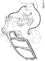
- Un exemple de réalisation de la présente invention va être décrit en relation avec les figures de la planche annexée, dans laquelle :
- -) la
figure 1 est une représentation d'un poste de lissage d'un cordon d'étanchéité ou de soudure sur des éléments de carrosserie d'un véhicule accolés, illustrant pour exemple un contexte d'application de l'invention. - -) la
figure 2 est une illustration en perspective éclatée d'un outil de lissage apte à équiper un manipulateur de lissage d'un cordon, tel que celui représenté pour exemple sur lafigure 1 . - Les figures et leurs descriptions détaillées exposent l'invention selon des modalités particulières qui ne sont pas restrictives quant à la portée de l'invention telle que définie par les revendications. Les figures et leurs descriptions détaillées peuvent servir à mieux définir l'invention, si besoin en relation avec la description générale qui vient d'en être faite.
- Sur la
figure 1 , deux éléments de carrosserie 1a, 1b d'un véhicule automobile sont accolés. Il est prévu de former un cordon 2 d'étanchéité et/ou de collage dans une jonction entre les bords des éléments de carrosserie 1a, 1b. La formation du cordon 2 comprend une opération de lissage du cordon telle qu'illustrée, après dépôt d'une matière pâteuse dont est issu le cordon 2. - A cet effet, un outil 3 de lissage est installé via son extrémité proximale 3a sur un manipulateur 4 configuré pour déplacer l'outil 3 dans l'espace euclidien le long du cordon 2 à lisser suivant une trajectoire prédéfinie. L'outil 3 comprend un support 5 pour son installation sur le manipulateur 4. Le support 5 est porteur à d'une cale 6 de lissage de la matière pâteuse dont est issu le cordon 2.
- Pour récupérer un surplus de matière du cordon 2 lissé par la cale 6, l'outil est équipé d'un système d'aspiration 7 de l'excès de matière. Un tel système d'aspiration 7 comprend un bac 7a de récupération de la matière en excès, qui est relié à l'outil 3 via un conduit 8. Pour générer la dépression à partir de laquelle l'excès de matière est collecté, le bac 7a est relié à un appareil générateur de dépression 7b, tel qu'une pompe à vide.
- Sur la
figure 2 , un outil 3 de lissage s'étend comme tout objet suivant trois dimensions d'un repère orthonormé, comprenant une direction longitudinale L1, une direction transversale T1 et une direction verticale V1. L'outil 3 de lissage s'étend essentiellement suivant la direction longitudinale L1 entre son extrémité proximale 3a prévue d'être fixée au manipulateur 4 et son extrémité distale 3b à laquelle est installée la cale 6. - Un tel outil 3 de lissage conforme à l'invention comprend le support 5 et la cale 6. La cale 6 est montée sur le support 5 via un corps 9 longitudinalement interposé entre eux. Le corps 9 est positionné par emboîtement sur le support 5 suivant la direction longitudinale L1 et la direction transversale T1. Le corps 9 est aussi retenu élastiquement sur le support 5 suivant la direction verticale V1, par un organe élastique 10.
- L'emboîtement du corps 9 sur le support 5 est réalisé via un premier moyen d'emboîtement 11a et un deuxième moyen d'emboîtement 11b.
- Le premier moyen d'emboîtement 11a associe des organes d'emboîtement 12a, 12b coopérants par coulissement qui sont respectivement ménagés sur le corps 9 et sur le support 5. Les organes d'emboîtement comprennent une glissière 12a qui est par exemple ménagée sur le corps 9, et un rail 12b qui est selon cet exemple inversement ménagé sur le support 5. La mise en coopération entre la glissière 12a et le rail 12b est réalisée transversalement T1 suivant un sens S1 d'emboîtement entre le corps 9 et le support 5.
- Le deuxième moyen d'emboîtement 11b associe des organes d'emboîtement 13a, 13b coopérants par coulissement qui sont respectivement ménagés sur le corps 9 et sur le support 5. Les organes d'emboîtement comprennent un doigt 13a qui est par exemple ménagée sur le corps 9, et un logement 13b de réception du doigt 13a. Le logement 13b est configuré en ouverture de passage du doigt 13a à son travers, en étant ménagé sur le support 5. La mise en coopération entre le doigt 13a et le logement 13b est réalisée transversalement T1 suivant le même sens S1 d'emboîtement transversal T1 entre le corps 9 et le support 5 via le premier moyen d'emboîtement 11a.
- Le support 5 comprend une patte 5a latérale s'étendant essentiellement longitudinalement L1 en prolongement longitudinal L1 de l'extrémité proximale d'un tronc 5b du support 5. La patte 5a s'étend longitudinalement L1 et verticalement V1, en ménageant une butée d'appui transversal du corps 9 contre le support 5 par suite de leur assemblage par emboîtement entre eux, suivant ledit sens S1 d'emboîtement transversal T1 via le premier moyen d'emboîtement 11a et le deuxième moyen d'emboîtement 11b.
- Le deuxième moyen d'emboîtement 11b est en outre configuré en moyen de pivotement vertical du corps 9 sur le support 5. Plus particulièrement, le doigt 13a est configuré en doigt 13a de pivotement vertical V1 du corps 9 sur le support 5. Le doigt 13a s'étend suivant un axe de pivot A1 d'extension transversale T1 et l'ouverture 13b ménage un palier de réception du doigt 13a.
- L'organe élastique 10 est placé en prise sur le corps 9 et conjointement sur le support 5 via la patte 5a. A cet effet, la patte 5a comporte au moins un premier organe d'accrochage 14 de l'organe élastique 10. Sur l'exemple illustré, le premier organe d'accrochage 14 est unique et s'étend verticalement V1 à l'extrémité proximale de la patte 5a. Le corps 9 comporte au moins un deuxième organe d'accrochage 15a, 15b de l'organe élastique 10, au nombre de deux sur l'exemple illustré.
- Les deuxièmes organes d'accrochage 15a, 15b sont ménagés à la face extérieure du corps 9 orientée vers la patte 5a en s'étendant transversalement T1. La patte 5a comporte au moins une échancrure 16a, 16b, au nombre de deux sur l'exemple illustré, qui débouchent verticalement V1 vers l'extérieur de la patte 5a. Les échancrures 16a, 16b ménagent chacune un passage transversal T1, à travers lesquels s'étendent respectivement les deuxièmes organes d'organes d'accrochage 15a, 15b en chevauchement de la patte 5a.
- Selon l'exemple illustré, l'organe élastique 10 est configuré en ressort en épingle 17. Un pontet 17c du ressort en épingle 17 est ménagé à son extrémité proximale pour être placé en prise sur le premier organe d'accrochage 14. Le pontet 17c est longitudinalement prolongé par des branches 17a, 17b configurées pour coopérer respectivement avec les deuxièmes organes d'accrochages 15a, 15b.
- Ainsi, le corps 9 est fixé sur le support 5 via l'organe élastique 10 formé par le ressort en épingle 17. On relèvera la présence souhaitée d'un guide 18 de positionnement du ressort en épingle 17 ménagé à la face extérieure de la patte 5a, contre lequel les branches 17a, 17b sont appliquées par suite de leurs mises en coopération avec les deuxième organes d'accrochage 15a, 15b.
- Le doigt 13a de pivot est placé à distance D1 longitudinale L1 du premier moyen d'emboîtement 11a. L'organe élastique 10 retient verticalement V1 le corps 9 sur le support 5, à l'encontre de son pivotement autour de l'axe de pivot A1. Ainsi l'organe élastique 10 contrôle un basculement élastique du corps 9 sur le support 5, selon l'effort d'application de la cale 6 le long du cordon 2 à lisser.
- La cale 6 est montée sur le corps 9 par emboîtement via des organes de jonction 19a, 19b configurés en organe de blocage de la cale 6 sur le corps 9. Ainsi, la cale 6 est fermement maintenue en position sur le corps 9 qui est monté flexible sur le support 5 via l'organe élastique 10.
- Un premier organe de jonction 19a configuré en cylindre 20a est configuré pour être logé à l'intérieur d'une alvéole 21a que comprend un deuxième organe de jonction 19b ménagé à l'intérieur de la cale 6. L'alvéole 21a est ménagée en fond d'une rainure 21b à son extrémité proximale. La rainure 21b forme un organe de guidage de la cale 6 lors de son montage sur le corps 9, via une assise 20b de la cale 6 qui est appliquée contre une paroi de la rainure 21b lorsque la cale 6 est montée sur le corps 9. Le deuxième organe de jonction 19b forme ainsi un organe de blocage de la cale 6 sur le corps 9, par enserrement élastique de la cale 6 à l'intérieur de l'alvéole 21b via le cylindre 20a.
- Par ailleurs l'outil est de préférence configuré pour permettre son équipement par un dit système d'aspiration 7. A cet effet, le support 5 comporte un canal 22a de circulation d'air muni d'un évent 22b. Le canal 22a s'étend longitudinalement L1 à travers le tronc 5b du support 5 et débouche à l'extrémité distale du tronc 5b. Le corps 9 est agencé en buse raccordable au canal 22a par suite de son emboîtement sur le support 5.
- Par suite de l'emboîtement du corps 9 et de son positionnement sur le support 5, le canal 22a est placé en communication fluidique avec la buse. Le débouché du canal 22a vers le corps 9 est ménagé par un embout du tronc 5b du support 5 qui forme le rail 12b constitutif de l'organe d'emboîtement 12b participant du premier moyen d'emboîtement 11a.
- Le canal 22a est prévu d'être raccordé à un dit conduit 8 du système d'aspiration 7 pour conduire, vers le bac 7a du système d'aspiration d'air 7, l'air qui est aspiré à travers l'évent 22b et qui entraîne les excès de matière du cordon 2 raclés par la cale 6 lors de son lissage.
- L'outil 3 est ainsi essentiellement composé de quatre composants comprenant le support 5, le corps 9, la cale 6 et l'organe élastique 10. Le remplacement de la cale 6 est ainsi rapide et aisé à réaliser par un opérateur.
- Pour monter une nouvelle cale 6, notamment après retrait d'une cale 6 usée, lesdits composants essentiels de l'outil 3 sont séparés suivant un processus inverse à celui de leur assemblage. Un tel processus d'assemblage comprend notamment les étapes successives suivantes effectuées par l'opérateur :
Dans une première étape, la cale 6 est installée sur le corps 9 par emboîtement. Cette première étape est notamment réalisée par insertion de la cale 6 à l'intérieur du corps 9 jusqu'à mise en coopération des dits organes de jonction 19a, 19b en butée longitudinale L1 l'un contre l'autre. - Selon l'exemple illustré, cette première étape est réalisée par insertion de la cale 6 à l'intérieur de la rainure 21b jusqu'à mise en coopération du cylindre 20a à l'intérieur de l'alvéole 21a. Les parois du corps 9 délimitant la rainure 21a sont aptes à autoriser par déformation élastique un coulissement de la cale 6 à l'intérieur de la rainure 21b, puis à enserrer la cale 6 via le cylindre 20a qui est placé en fond de la rainure 21b à l'intérieur de l'alvéole 21a.
- Dans une deuxième étape, le corps 9 muni de la cale 6 est installé par emboîtement coulissant sur le support 5, à partir d'une approche du corps 9 vers le support suivant ledit sens S1. Le corps 6 se trouve ainsi positionné transversalement T1 et longitudinalement L1 via conjointement le premier moyen d'emboîtement 11a et le deuxième moyen d'emboîtement 11b. On notera que le deuxième moyen d'emboîtement 11b forme alors un moyen d'indexage longitudinal-vertical L1-V1 du corps 9, et donc de de la cale 6, sur le support 5 par rapport au premier moyen d'emboîtement 11b.
- Selon l'exemple illustré, cette deuxième étape est réalisée par approche du corps 9 vers le support 5 suivant le dit sens S1, provoquant la mise en coopération conjointement d'une part du rail 12b à l'intérieur de la glissière 12a et d'autre part du doigt 13a de pivot à l'intérieur du logement 13b. Le corps 9 muni de la cale 6 est ainsi monté sur le support 5.
- Dans une troisième étape, l'organe élastique 10 est placé en interposition entre le corps 9 et le support 5 pour les fixer l'un à l'autre. L'organe élastique 10 est à cet effet installé sur le support 5, potentiellement à demeure, et est placé en prise sur le corps 9 monté sur le support 5, suivant un sens S2 transversal T1 opposé au sens S1 d'emboîtement entre le corps 9 et le support 5.
- Sur l'exemple illustré selon lequel l'organe élastique 10 est configuré en ressort en épingle 17, l'organe élastique 10 est placé en prise conjointe sur le support 5 et sur le corps 9 via les organes d'accrochage 15a, 15b et 14 dont sont respectivement munis le corps 9 et le support 5, plus spécifiquement la patte 5a.
- La cale 6 peut ainsi être remplacée aisément et facilement par l'opérateur, et cela de plus sans avoir à démonter l'outil 3 du manipulateur 4 et/ou sans avoir à rompre la liaison fluidique entre l'outil 3 et le système d'aspiration 7. En outre, les modalités de montage amovible de la cale 6 sur l'outil 3 n'affectent pas la rigueur de son positionnement sur l'outil 3, ni la faculté de la cale 6 à fléchir au besoin élastiquement selon les efforts d'application de la cale 6 sur le cordon 2 à lisser.
Claims (10)
- outil (3) de lissage d'un cordon (2) de matière pâteuse adhésive configuré pour son déplacement par un manipulateur (4) automatisé, l'outil (3) comprenant une cale (6) de lissage du cordon (2) montée sur un support (5), caractérisé en ce que suivant une direction longitudinale (L1) d'extension de l'outil (3) de lissage, l'outil (3) comprend successivement le support (5) et un corps (9) porteur de la cale (6), la cale (6) étant montée amovible sur le corps (9) en étant immobilisée sur le corps (9) dans l'espace euclidien et le corps (9) étant monté amovible sur le support (5) en étant positionné suivant des directions longitudinale (L1) et transversale (T1) et en étant retenu suivant une direction verticale (V1) via un organe élastique (10) qui est interposé en prise conjointe entre le support (5) et le corps (9).
- Outil (3) de lissage selon la revendication 1, caractérisé en ce que le support (5) comporte un canal (22a) de circulation d'air raccordable à un conduit (8) d'un système d'aspiration (7) équipant l'outil (3), le corps (9) étant agencé en buse et étant positionné communiquant avec ledit canal (22a) par suite de son montage sur le support (5).
- Outil (3) de lissage selon l'une quelconque des revendications 1 et 2, caractérisé en ce que le corps (9) et le support (5) sont assemblés l'un à l'autre par emboîtement réversible suivant une direction d'emboîtement transversale (T1), l'organe élastique (10) contrôlant un fléchissement élastique du corps (9) sur le support (5) autour d'un axe de pivot (A1) du corps (9) sur le support (5).
- Outil (3) de lissage selon la revendication 3, caractérisé en ce qu'un premier moyen d'emboîtement (11a) entre le support (5) et le corps (9) est ménagé à une extrémité proximale du corps (9) qui est longitudinalement (L1) opposée son extrémité distale via laquelle la cale (6) est montée sur le corps (9).
- Outil (3) de lissage selon la revendication 4, caractérisé en ce que le premier moyen d'emboîtement (11a) est configuré en un moyen de coulissement (12a,12b) transversal (T1) du corps (9) sur le support (5).
- Outil (3) de lissage selon l'une quelconque des revendications 4 et 5, caractérisé en ce qu'un deuxième moyen d'emboîtement (11b) entre le support (5) et le corps (9) est configuré en un moyen de pivotement du corps (9) sur le support (5) autour d'un axe de pivot (A1).
- Outil (3) de lissage selon la revendication 6, caractérisé en ce que le deuxième moyen d'emboîtement (11b) comprend un logement (13b) de réception transversale (T1) d'un doigt (13a) de pivot qui sont respectivement et indifféremment ménagés sur le corps (9) et sur le support (5).
- Outil (3) de lissage selon l'une quelconque des revendications précédentes, en ce que le support (5) comporte une patte (5a) latérale d'extension longitudinale-verticale (L1-V1) sur laquelle le corps (9) est fixé via l'organe élastique (10), la patte (5a) s'étendant longitudinalement en bordure du corps (9) en ménageant une butée d'appui transversal (T1) du corps (9) contre la patte (5a).
- Outil (3) de lissage selon l'une quelconque des revendications précédentes, en ce que l'organe élastique (10) est un ressort en épingle (17) d'extension longitudinale-verticale (L1-V1) conjointement fixé latéralement au support (5) et au corps (9) via des organes d'accrochage (14, 15, 15b) qu'ils comportent respectivement.
- Outil (3) de lissage la revendication 9, caractérisé en ce que le ressort en épingle (17) s'étend le long de la face extérieure de la patte (5a) en étant fixé au support (5) via un pontet (17c) qu'il comporte et qui est prolongé par des branches (17a, 17b), un couple d'organes d'accrochage (15, 15b) équipant le corps (9) chevauchant la patte (5a) pour la réception des branches (17a, 17b) du ressort en épingle (17).
Applications Claiming Priority (1)
| Application Number | Priority Date | Filing Date | Title |
|---|---|---|---|
| FR1760905A FR3073875A1 (fr) | 2017-11-20 | 2017-11-20 | Outil de lissage d'un cordon d'etancheite par raclage et/ou aspiration, muni d'une cale facilement interchangeable. |
Publications (2)
| Publication Number | Publication Date |
|---|---|
| EP3485983A1 true EP3485983A1 (fr) | 2019-05-22 |
| EP3485983B1 EP3485983B1 (fr) | 2022-04-20 |
Family
ID=61224045
Family Applications (1)
| Application Number | Title | Priority Date | Filing Date |
|---|---|---|---|
| EP18205040.1A Active EP3485983B1 (fr) | 2017-11-20 | 2018-11-07 | Outil de lissage d'un cordon d'etancheite par raclage et/ou aspiration, muni d'une cale facilement interchangeable |
Country Status (2)
| Country | Link |
|---|---|
| EP (1) | EP3485983B1 (fr) |
| FR (1) | FR3073875A1 (fr) |
Citations (4)
| Publication number | Priority date | Publication date | Assignee | Title |
|---|---|---|---|---|
| JPH0537373U (ja) * | 1991-10-24 | 1993-05-21 | 本田技研工業株式会社 | コーキング塗布ノズル |
| JP2017006885A (ja) * | 2015-06-25 | 2017-01-12 | 富士重工業株式会社 | シーラント整形装置及びシーラント塗布製品の製造方法 |
| JP2017039090A (ja) * | 2015-08-20 | 2017-02-23 | トヨタ自動車九州株式会社 | 粘性材料回収装置 |
| FR3045422A1 (fr) | 2015-12-22 | 2017-06-23 | Peugeot Citroen Automobiles Sa | Dispositif de lissage d'un cordon d’etancheite |
-
2017
- 2017-11-20 FR FR1760905A patent/FR3073875A1/fr not_active Ceased
-
2018
- 2018-11-07 EP EP18205040.1A patent/EP3485983B1/fr active Active
Patent Citations (4)
| Publication number | Priority date | Publication date | Assignee | Title |
|---|---|---|---|---|
| JPH0537373U (ja) * | 1991-10-24 | 1993-05-21 | 本田技研工業株式会社 | コーキング塗布ノズル |
| JP2017006885A (ja) * | 2015-06-25 | 2017-01-12 | 富士重工業株式会社 | シーラント整形装置及びシーラント塗布製品の製造方法 |
| JP2017039090A (ja) * | 2015-08-20 | 2017-02-23 | トヨタ自動車九州株式会社 | 粘性材料回収装置 |
| FR3045422A1 (fr) | 2015-12-22 | 2017-06-23 | Peugeot Citroen Automobiles Sa | Dispositif de lissage d'un cordon d’etancheite |
Also Published As
| Publication number | Publication date |
|---|---|
| FR3073875A1 (fr) | 2019-05-24 |
| EP3485983B1 (fr) | 2022-04-20 |
Similar Documents
| Publication | Publication Date | Title |
|---|---|---|
| EP2879921B1 (fr) | Dispositif de connexion entre un bras d'essuyage et un balai d'essuyage, comprenant un tube surmoule | |
| EP2879922B1 (fr) | Dispositif de connexion entre un bras d'essuyage et un balai d'essuyage, comprenant une zone amenagee pour recevoir une pluralite d'orifices de projection | |
| EP2691272B1 (fr) | Embout d'extremite a dispositif d'accrochage d'une lame d'essuyage | |
| WO2016050925A1 (fr) | Gicleur d'essuie-glace de véhicule | |
| EP2709880B1 (fr) | Dispositif de projection de liquide pour balai d'essuyage | |
| EP3300968B1 (fr) | Adaptateur constitutif d'un systeme d essuyage | |
| EP2861472B1 (fr) | Balai d'essuyage a connecteur hydraulique | |
| EP3300967A1 (fr) | Adaptateur constitutif d'un systeme d'essuyage | |
| EP3168092A1 (fr) | Organe pour un système de connexion d'un balai d'essuie-glace à un bras d'entraînement | |
| EP2707258B1 (fr) | Dispositif de projection de liquide pour balai d'essuyage | |
| FR3020389A1 (fr) | Outil a enduire avec zone de prehension a section circulaire | |
| FR2994146A1 (fr) | Systeme de connexion entre un bras d'essuyage et un balai d'essuyage | |
| EP3485983B1 (fr) | Outil de lissage d'un cordon d'etancheite par raclage et/ou aspiration, muni d'une cale facilement interchangeable | |
| EP2692598B1 (fr) | Dispositif de connexion entre un bras d'essuyage et un balai d'essuyage | |
| FR3023522A1 (fr) | Adaptateur de liaison d'un balai d'essuie-glace a un bras d'entrainement de ce balai | |
| FR3040155A1 (fr) | Dispositif de balai d'essuie-glace | |
| FR3045422B1 (fr) | Dispositif de lissage d'un cordon d’etancheite | |
| FR3026704A1 (fr) | Gicleur d'essuie-glace de vehicule | |
| FR3099998A1 (fr) | tête de sertissage intégrant une lame d’anglage | |
| EP3012163B1 (fr) | Dispositif de projection de liquide lave-glace pour un balai d essuyage de système d essuie-glace de véhicule | |
| FR2985223A1 (fr) | Dispositif modulaire de guidage d'une vitre de vehicule automobile. | |
| FR3039481A1 (fr) | Balai d'essuie-glace | |
| EP1873042A1 (fr) | Sous-ensemble de véhicule comportant des moyens de canalisation d'air | |
| FR3065691B1 (fr) | Embout d'extremite destine a un balai d'essuyage | |
| FR3103767A1 (fr) | Capot d’un dispositif d’essuyage de surface vitrée |
Legal Events
| Date | Code | Title | Description |
|---|---|---|---|
| PUAI | Public reference made under article 153(3) epc to a published international application that has entered the european phase |
Free format text: ORIGINAL CODE: 0009012 |
|
| STAA | Information on the status of an ep patent application or granted ep patent |
Free format text: STATUS: THE APPLICATION HAS BEEN PUBLISHED |
|
| AK | Designated contracting states |
Kind code of ref document: A1 Designated state(s): AL AT BE BG CH CY CZ DE DK EE ES FI FR GB GR HR HU IE IS IT LI LT LU LV MC MK MT NL NO PL PT RO RS SE SI SK SM TR |
|
| AX | Request for extension of the european patent |
Extension state: BA ME |
|
| STAA | Information on the status of an ep patent application or granted ep patent |
Free format text: STATUS: REQUEST FOR EXAMINATION WAS MADE |
|
| 17P | Request for examination filed |
Effective date: 20191120 |
|
| RBV | Designated contracting states (corrected) |
Designated state(s): AL AT BE BG CH CY CZ DE DK EE ES FI FR GB GR HR HU IE IS IT LI LT LU LV MC MK MT NL NO PL PT RO RS SE SI SK SM TR |
|
| RAP1 | Party data changed (applicant data changed or rights of an application transferred) |
Owner name: PSA AUTOMOBILES SA |
|
| GRAP | Despatch of communication of intention to grant a patent |
Free format text: ORIGINAL CODE: EPIDOSNIGR1 |
|
| STAA | Information on the status of an ep patent application or granted ep patent |
Free format text: STATUS: GRANT OF PATENT IS INTENDED |
|
| INTG | Intention to grant announced |
Effective date: 20211217 |
|
| GRAS | Grant fee paid |
Free format text: ORIGINAL CODE: EPIDOSNIGR3 |
|
| GRAA | (expected) grant |
Free format text: ORIGINAL CODE: 0009210 |
|
| STAA | Information on the status of an ep patent application or granted ep patent |
Free format text: STATUS: THE PATENT HAS BEEN GRANTED |
|
| AK | Designated contracting states |
Kind code of ref document: B1 Designated state(s): AL AT BE BG CH CY CZ DE DK EE ES FI FR GB GR HR HU IE IS IT LI LT LU LV MC MK MT NL NO PL PT RO RS SE SI SK SM TR |
|
| REG | Reference to a national code |
Ref country code: GB Ref legal event code: FG4D Free format text: NOT ENGLISH |
|
| REG | Reference to a national code |
Ref country code: CH Ref legal event code: EP |
|
| REG | Reference to a national code |
Ref country code: DE Ref legal event code: R096 Ref document number: 602018034075 Country of ref document: DE |
|
| REG | Reference to a national code |
Ref country code: IE Ref legal event code: FG4D Free format text: LANGUAGE OF EP DOCUMENT: FRENCH |
|
| REG | Reference to a national code |
Ref country code: DE Ref legal event code: R084 Ref document number: 602018034075 Country of ref document: DE |
|
| REG | Reference to a national code |
Ref country code: AT Ref legal event code: REF Ref document number: 1484756 Country of ref document: AT Kind code of ref document: T Effective date: 20220515 |
|
| REG | Reference to a national code |
Ref country code: GB Ref legal event code: 746 Effective date: 20220516 |
|
| REG | Reference to a national code |
Ref country code: LT Ref legal event code: MG9D |
|
| REG | Reference to a national code |
Ref country code: NL Ref legal event code: MP Effective date: 20220420 |
|
| REG | Reference to a national code |
Ref country code: AT Ref legal event code: MK05 Ref document number: 1484756 Country of ref document: AT Kind code of ref document: T Effective date: 20220420 |
|
| PG25 | Lapsed in a contracting state [announced via postgrant information from national office to epo] |
Ref country code: NL Free format text: LAPSE BECAUSE OF FAILURE TO SUBMIT A TRANSLATION OF THE DESCRIPTION OR TO PAY THE FEE WITHIN THE PRESCRIBED TIME-LIMIT Effective date: 20220420 |
|
| PG25 | Lapsed in a contracting state [announced via postgrant information from national office to epo] |
Ref country code: SE Free format text: LAPSE BECAUSE OF FAILURE TO SUBMIT A TRANSLATION OF THE DESCRIPTION OR TO PAY THE FEE WITHIN THE PRESCRIBED TIME-LIMIT Effective date: 20220420 Ref country code: PT Free format text: LAPSE BECAUSE OF FAILURE TO SUBMIT A TRANSLATION OF THE DESCRIPTION OR TO PAY THE FEE WITHIN THE PRESCRIBED TIME-LIMIT Effective date: 20220822 Ref country code: NO Free format text: LAPSE BECAUSE OF FAILURE TO SUBMIT A TRANSLATION OF THE DESCRIPTION OR TO PAY THE FEE WITHIN THE PRESCRIBED TIME-LIMIT Effective date: 20220720 Ref country code: LT Free format text: LAPSE BECAUSE OF FAILURE TO SUBMIT A TRANSLATION OF THE DESCRIPTION OR TO PAY THE FEE WITHIN THE PRESCRIBED TIME-LIMIT Effective date: 20220420 Ref country code: HR Free format text: LAPSE BECAUSE OF FAILURE TO SUBMIT A TRANSLATION OF THE DESCRIPTION OR TO PAY THE FEE WITHIN THE PRESCRIBED TIME-LIMIT Effective date: 20220420 Ref country code: GR Free format text: LAPSE BECAUSE OF FAILURE TO SUBMIT A TRANSLATION OF THE DESCRIPTION OR TO PAY THE FEE WITHIN THE PRESCRIBED TIME-LIMIT Effective date: 20220721 Ref country code: FI Free format text: LAPSE BECAUSE OF FAILURE TO SUBMIT A TRANSLATION OF THE DESCRIPTION OR TO PAY THE FEE WITHIN THE PRESCRIBED TIME-LIMIT Effective date: 20220420 Ref country code: ES Free format text: LAPSE BECAUSE OF FAILURE TO SUBMIT A TRANSLATION OF THE DESCRIPTION OR TO PAY THE FEE WITHIN THE PRESCRIBED TIME-LIMIT Effective date: 20220420 Ref country code: BG Free format text: LAPSE BECAUSE OF FAILURE TO SUBMIT A TRANSLATION OF THE DESCRIPTION OR TO PAY THE FEE WITHIN THE PRESCRIBED TIME-LIMIT Effective date: 20220720 Ref country code: AT Free format text: LAPSE BECAUSE OF FAILURE TO SUBMIT A TRANSLATION OF THE DESCRIPTION OR TO PAY THE FEE WITHIN THE PRESCRIBED TIME-LIMIT Effective date: 20220420 |
|
| PG25 | Lapsed in a contracting state [announced via postgrant information from national office to epo] |
Ref country code: RS Free format text: LAPSE BECAUSE OF FAILURE TO SUBMIT A TRANSLATION OF THE DESCRIPTION OR TO PAY THE FEE WITHIN THE PRESCRIBED TIME-LIMIT Effective date: 20220420 Ref country code: PL Free format text: LAPSE BECAUSE OF FAILURE TO SUBMIT A TRANSLATION OF THE DESCRIPTION OR TO PAY THE FEE WITHIN THE PRESCRIBED TIME-LIMIT Effective date: 20220420 Ref country code: LV Free format text: LAPSE BECAUSE OF FAILURE TO SUBMIT A TRANSLATION OF THE DESCRIPTION OR TO PAY THE FEE WITHIN THE PRESCRIBED TIME-LIMIT Effective date: 20220420 Ref country code: IS Free format text: LAPSE BECAUSE OF FAILURE TO SUBMIT A TRANSLATION OF THE DESCRIPTION OR TO PAY THE FEE WITHIN THE PRESCRIBED TIME-LIMIT Effective date: 20220820 |
|
| REG | Reference to a national code |
Ref country code: DE Ref legal event code: R097 Ref document number: 602018034075 Country of ref document: DE |
|
| PG25 | Lapsed in a contracting state [announced via postgrant information from national office to epo] |
Ref country code: SM Free format text: LAPSE BECAUSE OF FAILURE TO SUBMIT A TRANSLATION OF THE DESCRIPTION OR TO PAY THE FEE WITHIN THE PRESCRIBED TIME-LIMIT Effective date: 20220420 Ref country code: SK Free format text: LAPSE BECAUSE OF FAILURE TO SUBMIT A TRANSLATION OF THE DESCRIPTION OR TO PAY THE FEE WITHIN THE PRESCRIBED TIME-LIMIT Effective date: 20220420 Ref country code: RO Free format text: LAPSE BECAUSE OF FAILURE TO SUBMIT A TRANSLATION OF THE DESCRIPTION OR TO PAY THE FEE WITHIN THE PRESCRIBED TIME-LIMIT Effective date: 20220420 Ref country code: EE Free format text: LAPSE BECAUSE OF FAILURE TO SUBMIT A TRANSLATION OF THE DESCRIPTION OR TO PAY THE FEE WITHIN THE PRESCRIBED TIME-LIMIT Effective date: 20220420 Ref country code: DK Free format text: LAPSE BECAUSE OF FAILURE TO SUBMIT A TRANSLATION OF THE DESCRIPTION OR TO PAY THE FEE WITHIN THE PRESCRIBED TIME-LIMIT Effective date: 20220420 Ref country code: CZ Free format text: LAPSE BECAUSE OF FAILURE TO SUBMIT A TRANSLATION OF THE DESCRIPTION OR TO PAY THE FEE WITHIN THE PRESCRIBED TIME-LIMIT Effective date: 20220420 |
|
| PLBE | No opposition filed within time limit |
Free format text: ORIGINAL CODE: 0009261 |
|
| STAA | Information on the status of an ep patent application or granted ep patent |
Free format text: STATUS: NO OPPOSITION FILED WITHIN TIME LIMIT |
|
| 26N | No opposition filed |
Effective date: 20230123 |
|
| PG25 | Lapsed in a contracting state [announced via postgrant information from national office to epo] |
Ref country code: AL Free format text: LAPSE BECAUSE OF FAILURE TO SUBMIT A TRANSLATION OF THE DESCRIPTION OR TO PAY THE FEE WITHIN THE PRESCRIBED TIME-LIMIT Effective date: 20220420 |
|
| PG25 | Lapsed in a contracting state [announced via postgrant information from national office to epo] |
Ref country code: SI Free format text: LAPSE BECAUSE OF FAILURE TO SUBMIT A TRANSLATION OF THE DESCRIPTION OR TO PAY THE FEE WITHIN THE PRESCRIBED TIME-LIMIT Effective date: 20220420 |
|
| PG25 | Lapsed in a contracting state [announced via postgrant information from national office to epo] |
Ref country code: MC Free format text: LAPSE BECAUSE OF FAILURE TO SUBMIT A TRANSLATION OF THE DESCRIPTION OR TO PAY THE FEE WITHIN THE PRESCRIBED TIME-LIMIT Effective date: 20220420 |
|
| REG | Reference to a national code |
Ref country code: CH Ref legal event code: PL |
|
| REG | Reference to a national code |
Ref country code: BE Ref legal event code: MM Effective date: 20221130 |
|
| PG25 | Lapsed in a contracting state [announced via postgrant information from national office to epo] |
Ref country code: LI Free format text: LAPSE BECAUSE OF NON-PAYMENT OF DUE FEES Effective date: 20221130 Ref country code: CH Free format text: LAPSE BECAUSE OF NON-PAYMENT OF DUE FEES Effective date: 20221130 |
|
| PG25 | Lapsed in a contracting state [announced via postgrant information from national office to epo] |
Ref country code: LU Free format text: LAPSE BECAUSE OF NON-PAYMENT OF DUE FEES Effective date: 20221107 |
|
| PG25 | Lapsed in a contracting state [announced via postgrant information from national office to epo] |
Ref country code: IE Free format text: LAPSE BECAUSE OF NON-PAYMENT OF DUE FEES Effective date: 20221107 |
|
| PG25 | Lapsed in a contracting state [announced via postgrant information from national office to epo] |
Ref country code: BE Free format text: LAPSE BECAUSE OF NON-PAYMENT OF DUE FEES Effective date: 20221130 |
|
| PG25 | Lapsed in a contracting state [announced via postgrant information from national office to epo] |
Ref country code: IT Free format text: LAPSE BECAUSE OF FAILURE TO SUBMIT A TRANSLATION OF THE DESCRIPTION OR TO PAY THE FEE WITHIN THE PRESCRIBED TIME-LIMIT Effective date: 20220420 |
|
| PG25 | Lapsed in a contracting state [announced via postgrant information from national office to epo] |
Ref country code: HU Free format text: LAPSE BECAUSE OF FAILURE TO SUBMIT A TRANSLATION OF THE DESCRIPTION OR TO PAY THE FEE WITHIN THE PRESCRIBED TIME-LIMIT; INVALID AB INITIO Effective date: 20181107 |
|
| REG | Reference to a national code |
Ref country code: DE Ref legal event code: R081 Ref document number: 602018034075 Country of ref document: DE Owner name: STELLANTIS AUTO SAS, FR Free format text: FORMER OWNER: PSA AUTOMOBILES SA, POISSY, FR |
|
| PG25 | Lapsed in a contracting state [announced via postgrant information from national office to epo] |
Ref country code: CY Free format text: LAPSE BECAUSE OF FAILURE TO SUBMIT A TRANSLATION OF THE DESCRIPTION OR TO PAY THE FEE WITHIN THE PRESCRIBED TIME-LIMIT Effective date: 20220420 |
|
| PG25 | Lapsed in a contracting state [announced via postgrant information from national office to epo] |
Ref country code: MK Free format text: LAPSE BECAUSE OF FAILURE TO SUBMIT A TRANSLATION OF THE DESCRIPTION OR TO PAY THE FEE WITHIN THE PRESCRIBED TIME-LIMIT Effective date: 20220420 |
|
| PG25 | Lapsed in a contracting state [announced via postgrant information from national office to epo] |
Ref country code: TR Free format text: LAPSE BECAUSE OF FAILURE TO SUBMIT A TRANSLATION OF THE DESCRIPTION OR TO PAY THE FEE WITHIN THE PRESCRIBED TIME-LIMIT Effective date: 20220420 |
|
| PG25 | Lapsed in a contracting state [announced via postgrant information from national office to epo] |
Ref country code: MT Free format text: LAPSE BECAUSE OF FAILURE TO SUBMIT A TRANSLATION OF THE DESCRIPTION OR TO PAY THE FEE WITHIN THE PRESCRIBED TIME-LIMIT Effective date: 20220420 |
|
| PG25 | Lapsed in a contracting state [announced via postgrant information from national office to epo] |
Ref country code: BG Free format text: LAPSE BECAUSE OF FAILURE TO SUBMIT A TRANSLATION OF THE DESCRIPTION OR TO PAY THE FEE WITHIN THE PRESCRIBED TIME-LIMIT Effective date: 20220420 |
|
| PG25 | Lapsed in a contracting state [announced via postgrant information from national office to epo] |
Ref country code: BG Free format text: LAPSE BECAUSE OF FAILURE TO SUBMIT A TRANSLATION OF THE DESCRIPTION OR TO PAY THE FEE WITHIN THE PRESCRIBED TIME-LIMIT Effective date: 20220420 |
|
| PGFP | Annual fee paid to national office [announced via postgrant information from national office to epo] |
Ref country code: DE Payment date: 20251022 Year of fee payment: 8 |
|
| PGFP | Annual fee paid to national office [announced via postgrant information from national office to epo] |
Ref country code: GB Payment date: 20251023 Year of fee payment: 8 |
|
| PGFP | Annual fee paid to national office [announced via postgrant information from national office to epo] |
Ref country code: FR Payment date: 20251022 Year of fee payment: 8 |