EP3485503B1 - Electrical transmission in an endblock for a sputter device - Google Patents
Electrical transmission in an endblock for a sputter device Download PDFInfo
- Publication number
- EP3485503B1 EP3485503B1 EP17749217.0A EP17749217A EP3485503B1 EP 3485503 B1 EP3485503 B1 EP 3485503B1 EP 17749217 A EP17749217 A EP 17749217A EP 3485503 B1 EP3485503 B1 EP 3485503B1
- Authority
- EP
- European Patent Office
- Prior art keywords
- power transmission
- transmission system
- endblock
- sputter
- contact surface
- Prior art date
- Legal status (The legal status is an assumption and is not a legal conclusion. Google has not performed a legal analysis and makes no representation as to the accuracy of the status listed.)
- Active
Links
Images


Classifications
-
- H—ELECTRICITY
- H01—ELECTRIC ELEMENTS
- H01J—ELECTRIC DISCHARGE TUBES OR DISCHARGE LAMPS
- H01J37/00—Discharge tubes with provision for introducing objects or material to be exposed to the discharge, e.g. for the purpose of examination or processing thereof
- H01J37/32—Gas-filled discharge tubes
- H01J37/32431—Constructional details of the reactor
- H01J37/32532—Electrodes
- H01J37/32577—Electrical connecting means
-
- H—ELECTRICITY
- H01—ELECTRIC ELEMENTS
- H01J—ELECTRIC DISCHARGE TUBES OR DISCHARGE LAMPS
- H01J37/00—Discharge tubes with provision for introducing objects or material to be exposed to the discharge, e.g. for the purpose of examination or processing thereof
- H01J37/32—Gas-filled discharge tubes
- H01J37/34—Gas-filled discharge tubes operating with cathodic sputtering
- H01J37/3411—Constructional aspects of the reactor
- H01J37/3435—Target holders (includes backing plates and endblocks)
-
- H—ELECTRICITY
- H01—ELECTRIC ELEMENTS
- H01J—ELECTRIC DISCHARGE TUBES OR DISCHARGE LAMPS
- H01J37/00—Discharge tubes with provision for introducing objects or material to be exposed to the discharge, e.g. for the purpose of examination or processing thereof
- H01J37/32—Gas-filled discharge tubes
- H01J37/34—Gas-filled discharge tubes operating with cathodic sputtering
- H01J37/3411—Constructional aspects of the reactor
- H01J37/3444—Associated circuits
-
- H—ELECTRICITY
- H01—ELECTRIC ELEMENTS
- H01J—ELECTRIC DISCHARGE TUBES OR DISCHARGE LAMPS
- H01J37/00—Discharge tubes with provision for introducing objects or material to be exposed to the discharge, e.g. for the purpose of examination or processing thereof
- H01J37/32—Gas-filled discharge tubes
- H01J37/34—Gas-filled discharge tubes operating with cathodic sputtering
- H01J37/3488—Constructional details of particle beam apparatus not otherwise provided for, e.g. arrangement, mounting, housing, environment; special provisions for cleaning or maintenance of the apparatus
- H01J37/3497—Temperature of target
-
- C—CHEMISTRY; METALLURGY
- C23—COATING METALLIC MATERIAL; COATING MATERIAL WITH METALLIC MATERIAL; CHEMICAL SURFACE TREATMENT; DIFFUSION TREATMENT OF METALLIC MATERIAL; COATING BY VACUUM EVAPORATION, BY SPUTTERING, BY ION IMPLANTATION OR BY CHEMICAL VAPOUR DEPOSITION, IN GENERAL; INHIBITING CORROSION OF METALLIC MATERIAL OR INCRUSTATION IN GENERAL
- C23C—COATING METALLIC MATERIAL; COATING MATERIAL WITH METALLIC MATERIAL; SURFACE TREATMENT OF METALLIC MATERIAL BY DIFFUSION INTO THE SURFACE, BY CHEMICAL CONVERSION OR SUBSTITUTION; COATING BY VACUUM EVAPORATION, BY SPUTTERING, BY ION IMPLANTATION OR BY CHEMICAL VAPOUR DEPOSITION, IN GENERAL
- C23C14/00—Coating by vacuum evaporation, by sputtering or by ion implantation of the coating forming material
- C23C14/22—Coating by vacuum evaporation, by sputtering or by ion implantation of the coating forming material characterised by the process of coating
- C23C14/34—Sputtering
Definitions
- This invention relates in general to a power transmission system for an endblock in a sputter device for transmitting power to the sputter target, and to an endblock which comprises such a power transmission system, and to a corresponding sputter device.
- An endblock connects the sputter target in the sputter system to the outside of the sputter system.
- Such an endblock is typically mountable as a component on the sputter system.
- the pressure may be higher than in the sputter system.
- the pressure may for example be close to atmospheric pressure.
- Components which can be removed together with the sputter target, or the removable magnet configuration, are typically not regarded as fixedly belonging to the endblock.
- the main function of the endblock is to carry the sputter target and rotate the sputter target around the rotation axis. Since sputtering takes place with a gas at low gas pressure, the endblock must be vacuum-tight even during rotation of the sputter target.
- the sputter target Since sputtering of a sputter target can generate a great deal of heat on the sputter target surface, the sputter target must also be cooled. This is typically achieved with water or another suitable coolant. The coolant must be supplied and evacuated via the endblock.
- the sputter target must also be supplied with an electrical current in order to bring the sputter target to a specific electrical potential. More specifically, in the endblock, power from the static part of the endblock is transferred to the rotating part of the endblock.
- each endblock must comprise one or more of the following means: (i) drive means for causing the sputter target to rotate, (ii) a rotatable electrical contact means for obtaining electrical current on the sputter target, (iii) one or more bearings for supporting the sputter target mechanically while it rotates around its axis, (iv) one or more rotatable sealing means for coolant, (v) one or more rotatable vacuum sealing means, and (vi) means for positioning the magnets or a series of magnets.
- Double right-angled endblocks as described in US 5,096,562 ( FIG. 2 and FIG. 6 ) and in US 2003/0136672 A1 , are endblocks in which the bearing means, the rotation means, the means for electrical supply, the means for cooling and the means for isolation (air, coolant, electrical) are distributed over two endblocks, each situated at one end of the sputter target.
- “Right-angled” means that the endblocks are mounted on the wall parallel to the rotation axis of the sputter target.
- Single rectilinear endblocks as described in US 5,200,049 ( FIG. 1 ) are endblocks in which the bearing means, the rotation means, the means for electrical supply, the means for cooling and the means for isolation (air, coolant, electrical) are all combined in one endblock.
- the sputter target is here mounted on the endblock.
- rectilinear means that the rotation axis of the sputter target stands perpendicular to the wall on which the endblock is mounted.
- Hybrid configurations for endblocks are described in US 5,620,577 wherein the end of the sputter target, located opposite the end of the sputter target in which the endblock is provided, is supported by a mechanical support element.
- the power is transferred in a part of the endblock in which no coolant water is present.
- carbon brushes may be used to transfer the power from the static part of the endblock to the rotating part of the endblock.
- a power transmission system is provided which can be used in a part of the endblock in which coolant water is present.
- the present invention concerns a power transmission system, according to claim 1, for transmission of electrical power to a sputter target in a sputter device.
- the three parts of the power transmission system are preferably such that they are electrically conductive, so that the power transfer system can transmit electrical power for the sputter target.
- the power transmission system is easy to install, remove and refit. It is an advantage of embodiments of the present invention in relation to existing systems that there is no need to attach a large number of wires with adjustment screws, which offers a substantial time-saving and simplicity of installation.
- the at least two of the three parts of the power transmission system may be made as one monolithic piece. It is an advantage of embodiments of the present invention that a power transmission system is provided in which fewer separate elements are present which need each be adjusted individually.
- the at least two of the three parts of the power transmission system can be made from a single material.
- the three parts of the power transmission system can be made as a single monolithic piece.
- the power transmission system may for example be 3D-printed, although embodiments are not restricted to this.
- the spring part may be made from an electrically conductive material.
- the spring material may itself be electrically conductive so that the spring material ensures the power transmission.
- the contact surface of the first part may be adapted to form a slide contact with the endblock.
- the contact surface of the third part may be adapted to form a slide contact with the endblock.
- the first part of the endblock may be rotatable in order to rotate the sputter target during a sputter operation.
- the second part of the endblock may be rotatable in order to rotate the sputter target during a sputter operation.
- the contact surface of the first part and/or the third part of the power transmission system may be formed such that there are several contact areas between the contact surface and the endblock, distributed over the respective contact surface, when the sputter device is in the static state.
- the second part of the power transmission system may be the spring and electrically conductive part.
- the power transmission system when mounted in an endblock and the corresponding sputter installation is in operation, may be positioned in cooling water. It is an advantage of embodiments of the present invention that optimum cooling is provided because the power transmission system itself stands in cooling water during use.
- the first part of the power transmission system may have a cylindrical form to adjoin the first part of the endblock.
- the third part may have a cylindrical form adapted to adjoin the second part of the endblock.
- At least the spring part may be made of a copper-beryllium or copper-tin alloy. It is an advantage of embodiments of the present invention that the materials used provide adequate electrical conductivity and at the same time allow sufficient elastic deformation so that the first or third part makes good contact with the rotating part of the endblock.
- An additional layer may be present on the contact surface of the first and/or third part of the power transmission system.
- the use of an additional layer allows the material of this layer to be selected such that the material results in a lubricating function on the contact surface.
- the additional layer may be renewable after wear.
- the additional layer may be thermally attached to the core.
- the additional layer may be made of an alloy which contains tin and copper, or an alloy which contains copper or carbon.
- the first part or the third part of the power transmission system may comprise cylindrical elements, wherein the surfaces of the cylindrical elements are chromed and are formed such that they conform respectively to the first part of the endblock or the second part of the endblock or the sputter target, and wherein the cylindrical elements can be pressed radially against the sputter target or the second part of the endblock by the spring part.
- the second part of the power transmission system may comprise one or more helical springs.
- the first part and/or the second part of the power transmission system may have a sprung cylindrical form.
- the first and/or second part of the power transmission system may consist of a meandering plate placed in a cylindrical surface.
- the first part and/or the third part of the power transmission system may be formed as a spongy electrically conductive structure.
- the power transmission system may be formed such that the third part of the power transmission system is pressed axially against the edge of the sputter target and/or the edge of the second part of the endblock, wherein the second part of the endblock is adapted to rotate the sputter target.
- the present invention concerns an endblock for a sputter device, according to claim 14, which comprises a power transmission system as described above.
- the present invention concerns a sputter device, according to claim 15, which comprises a power transmission system as described above.
- the present invention concerns a power transmission system for the transmission of electrical power to a sputter target in a sputter device. More specifically, it concerns the transmission of power in a sputter device in which a rotating sputter target is used.
- sputter targets are often rotationally symmetrical sputter targets such as cylindrical sputter targets.
- the sputter target is mounted on an endblock.
- the endblock has the function amongst others of rotating the sputter target and transmitting electrical power from a static part of the endblock to the dynamic part of the endblock on which the sputter target is mounted.
- the power transmission system is the means by which this transmission of electrical power is implemented.
- the power transmission system 100 comprises a first part 110 comprising a contact surface 115 which is positionable against a first part 210 of an endblock 200 of the sputter device. It also comprises a second part 120 which is inseparably connected to the first part 110 and a third part 130. It therefore also comprises a third part 130 comprising a contact surface 135 positionable against a second part 220 of the endblock 200.
- a first part 110 comprising a contact surface 115 which is positionable against a first part 210 of an endblock 200 of the sputter device. It also comprises a second part 120 which is inseparably connected to the first part 110 and a third part 130. It therefore also comprises a third part 130 comprising a contact surface 135 positionable against a second part 220 of the endblock 200.
- at least two of the three parts 110, 120, 130 of the power transmission system 100 are formed monolithically.
- at least two of the three parts may be made of the same material.
- one of the three parts 110, 120, 130 is configured such that it is resilient, so that when the power transmission system 100 is installed, the power transmission system 100 is clamped between the first part 210 of the endblock 200 and the second part 220 of the endblock 200.
- this part is also responsible for the transmission of electrical power to the sputter target. This may avoid the need for separate wiring.
- the configuration is such that typically, one of the parts 110, 120, 130 is in contact with a static part of the endblock while another part is in contact with the dynamic part of the endblock. Both the first part of the endblock and the second part of the endblock can function as the dynamic part on which the sputter target is mounted.
- the slide contact formed by the power transmission system 100 lies both against the dynamic part of the endblock 200 and against the static part of the endblock 200. In the first case, the power transmission system 100 is static, while in the second case the power transmission 100 moves with the dynamic part of the endblock.
- the first part 110 is shown as being the innermost part of the power transmission system 100, which in this case is connected to the static part of the endblock 200
- the third part 130 is shown as the outermost part of the power transmission system, which forms a slide contact against the dynamic part of the endblock 200
- the dynamic part of the endblock 200 (on which the target is mounted and which rotates) may be provided both centrally and on the outer edge of the endblock 200, and the slide contact provided for the power transmission system 100 may be provided both against the dynamic and against the static part of the endblock 200.
- At least two of the three parts are made from the same material.
- all parts of the power transmission system 100 are made of the same material (possibly with an additional layer).
- the material may be a sprung material which at the same time is electrically conductive.
- this material may be a copper-beryllium alloy. In another embodiment, this material may be a copper-tin alloy.
- At least two or all different parts of the power transmission system are made as one monolithic piece.
- the contact surface 115, 135 of the first part 110 and/or the third part 130 which behaves as a slide contact is formed such that it has several contact regions with the endblock 200 when the sputter device is in the static state, i.e. when the sputter target is not rotating.
- the contact surface 115, 135 may for example be annular, or combine various separate contact surfaces located for example on a single annular surface.
- the slide contact is provided with an additional layer.
- This layer may for example be renewable after wear.
- This additional layer may be attached to the power transmission system by means of thermal bonding, although embodiments are not restricted to this.
- Such an additional layer may for example be selected such that it has a lubricating function. It may for example be made from an alloy which comprises tin and copper, or from an alloy which comprises copper or carbon.
- FIG. 1 shows part of an endblock 200 in which the power transmission system 100 is positioned.
- FIG. 2 illustrates another example of a power transmission system 100 (right) and an endblock 200 (left) in which such a power transmission system 100 is installed.
- the power transmission system 100 in the present example has a second part 120 in the form of a helical spring. This supplies the necessary spring force to press the first part 110 and the third part 130 against the static part and the dynamic part of the endblock. Since in the present example all three of the elements are electrically conductive, the power can be transmitted via this power transmission J system 100.
- FIG. 3 illustrates an alternative example in which again a first part 110, a second part 120 and a third part 130 of the power transmission system 100 are shown.
- the second part again provides the necessary spring force for pressing the first part 110 and the third part 130 against the static and dynamic part of the endblock.
- the contact surface from the third part 130 takes the form of a meander which ensures a large contact surface for power transmission.
- FIG. 4 shows a further alternative example which uses an ondular spring.
- an axial force is exerted rather than a radial force.
- a system may also be used in which a radial force is exerted in order to clamp the power transmission system.
- Such an embodiment may for example result from the embodiment in FIG. 4 by changing the oblique side, shown on the left of the figure, so that it stands perpendicular to the axis, whereby a radial force is exerted by the spring system.
- FIG. 5 illustrates a further alternative in which the power transmission system comprises a spring element with a spongy structure.
- This spring element also provides a spring force, whereby the power transmission system presses on one side against the static part and on the other side against the dynamic part of the endblock.
- FIG. 6 to FIG. 8 illustrate further examples of power transmission systems in which the second part is a spring element.
- the spring force of this spring element is obtained by the specific form in which the material is folded, in combination with the material used. It is an advantage of some embodiments of the present invention that a large contact area can be obtained between the power transmission system and the endblock.
- FIG. 6 and FIG. 7 also show an additional layer 140 positioned on the third element. Such a layer may improve the electrical contact between the power transmission system and the endblock.
- the present invention also concerns an endblock which comprises a power transmission system as described above.
- an endblock which comprises a power transmission system as described above.
- Features and advantages of the sputter device correspond to features and advantages of the power transmission system as described above.
- the present invention also concerns a sputter device which comprises an endblock as described above.
- a sputter device which comprises an endblock as described above.
- Features and advantages of the sputter device correspond to features and advantages of the endblock as described above.
- the invention is defined by the claims.
Landscapes
- Physics & Mathematics (AREA)
- Engineering & Computer Science (AREA)
- Plasma & Fusion (AREA)
- Chemical & Material Sciences (AREA)
- Analytical Chemistry (AREA)
- Physical Vapour Deposition (AREA)
Description
- This invention relates in general to a power transmission system for an endblock in a sputter device for transmitting power to the sputter target, and to an endblock which comprises such a power transmission system, and to a corresponding sputter device.
- An endblock connects the sputter target in the sputter system to the outside of the sputter system. Such an endblock is typically mountable as a component on the sputter system. In parts of the endblock, the pressure may be higher than in the sputter system. The pressure may for example be close to atmospheric pressure. Components which can be removed together with the sputter target, or the removable magnet configuration, are typically not regarded as fixedly belonging to the endblock. The main function of the endblock is to carry the sputter target and rotate the sputter target around the rotation axis. Since sputtering takes place with a gas at low gas pressure, the endblock must be vacuum-tight even during rotation of the sputter target.
- Since sputtering of a sputter target can generate a great deal of heat on the sputter target surface, the sputter target must also be cooled. This is typically achieved with water or another suitable coolant. The coolant must be supplied and evacuated via the endblock.
- The sputter target must also be supplied with an electrical current in order to bring the sputter target to a specific electrical potential. More specifically, in the endblock, power from the static part of the endblock is transferred to the rotating part of the endblock.
- In order to incorporate these different functionalities, each endblock must comprise one or more of the following means: (i) drive means for causing the sputter target to rotate, (ii) a rotatable electrical contact means for obtaining electrical current on the sputter target, (iii) one or more bearings for supporting the sputter target mechanically while it rotates around its axis, (iv) one or more rotatable sealing means for coolant, (v) one or more rotatable vacuum sealing means, and (vi) means for positioning the magnets or a series of magnets.
- For combining these functionalities, various configurations of endblocks are already available in the prior art.
- "Double right-angled endblocks" as described in
US 5,096,562 (FIG. 2 andFIG. 6 ) and inUS 2003/0136672 A1 , are endblocks in which the bearing means, the rotation means, the means for electrical supply, the means for cooling and the means for isolation (air, coolant, electrical) are distributed over two endblocks, each situated at one end of the sputter target. "Right-angled" means that the endblocks are mounted on the wall parallel to the rotation axis of the sputter target. - "Single rectilinear endblocks" as described in
US 5,200,049 (FIG. 1 ) are endblocks in which the bearing means, the rotation means, the means for electrical supply, the means for cooling and the means for isolation (air, coolant, electrical) are all combined in one endblock. The sputter target is here mounted on the endblock. The term "rectilinear" means that the rotation axis of the sputter target stands perpendicular to the wall on which the endblock is mounted. - Hybrid configurations for endblocks are described in
US 5,620,577 wherein the end of the sputter target, located opposite the end of the sputter target in which the endblock is provided, is supported by a mechanical support element. - Conventionally, the power is transferred in a part of the endblock in which no coolant water is present. In such a configuration, carbon brushes may be used to transfer the power from the static part of the endblock to the rotating part of the endblock.
- Correct adjustment of the carbon brushes is achieved by means of a series of adjustment screws, and is a time-intensive task. In addition, correct adjustment must be performed repeatedly because the carbon brushes are subject to wear and must therefore be replaced regularly. There is a need for a system for power transfer which can be installed or replaced in an efficient manner.
- In addition, in some cases it is advantageous to form the power transfer between the static part of the endblock and the dynamic part of the endblock in a part of the endblock where coolant is present. The use of carbon brushes in such a configuration is excluded since carbon brushes degrade in a watery environment due to corrosion, and since the lubricating layer, which is typically used to generate a low mechanical and electrical resistance, dissipates rapidly in a watery environment. Document
WO 2006/042808 A1 discloses an end-block for electrically energising a rotatable tubular target by increasing the number of contact areas between a contacting ring and a series of circumferentially mounted contacting shoes. The shoes are pressed radially outwardly by means of resilient elements against the contacting ring. - It is an object of the present invention to provide efficient means and systems for transmission of electrical power in an endblock for a sputter device.
- It is an advantage of at least some embodiments of the present invention that a power transmission system is provided which is simple to install.
- It is an advantage of at least some embodiments of the present invention that a power transmission system is provided which can be used in a part of the endblock in which coolant water is present.
- The above-mentioned object is achieved by means and systems according to the present invention.
- In one aspect, the present invention concerns a power transmission system, according to claim 1, for transmission of electrical power to a sputter target in a sputter device.
- It is an advantage of embodiments of the present invention that separate auxiliary wiring in the endblock for providing the transmission of electrical power can be omitted. The electrical power can be transmitted by means of electrical current passage.
- The three parts of the power transmission system are preferably such that they are electrically conductive, so that the power transfer system can transmit electrical power for the sputter target.
- It is an advantage of embodiments of the present invention that the power transmission system is easy to install, remove and refit. It is an advantage of embodiments of the present invention in relation to existing systems that there is no need to attach a large number of wires with adjustment screws, which offers a substantial time-saving and simplicity of installation.
- It is an advantage of embodiments of the present invention that the power transmission system allows simple replacement.
- The at least two of the three parts of the power transmission system may be made as one monolithic piece. It is an advantage of embodiments of the present invention that a power transmission system is provided in which fewer separate elements are present which need each be adjusted individually.
- The at least two of the three parts of the power transmission system can be made from a single material.
- The three parts of the power transmission system can be made as a single monolithic piece. The power transmission system may for example be 3D-printed, although embodiments are not restricted to this.
- The spring part may be made from an electrically conductive material. In embodiments of the present invention, the spring material may itself be electrically conductive so that the spring material ensures the power transmission.
- The contact surface of the first part may be adapted to form a slide contact with the endblock.
- The contact surface of the third part may be adapted to form a slide contact with the endblock.
- The first part of the endblock may be rotatable in order to rotate the sputter target during a sputter operation.
- The second part of the endblock may be rotatable in order to rotate the sputter target during a sputter operation.
- The contact surface of the first part and/or the third part of the power transmission system may be formed such that there are several contact areas between the contact surface and the endblock, distributed over the respective contact surface, when the sputter device is in the static state.
- The second part of the power transmission system may be the spring and electrically conductive part.
- The power transmission system, when mounted in an endblock and the corresponding sputter installation is in operation, may be positioned in cooling water. It is an advantage of embodiments of the present invention that optimum cooling is provided because the power transmission system itself stands in cooling water during use.
- The first part of the power transmission system may have a cylindrical form to adjoin the first part of the endblock. The third part may have a cylindrical form adapted to adjoin the second part of the endblock.
- At least the spring part may be made of a copper-beryllium or copper-tin alloy. It is an advantage of embodiments of the present invention that the materials used provide adequate electrical conductivity and at the same time allow sufficient elastic deformation so that the first or third part makes good contact with the rotating part of the endblock.
- An additional layer may be present on the contact surface of the first and/or third part of the power transmission system. The use of an additional layer allows the material of this layer to be selected such that the material results in a lubricating function on the contact surface.
- The additional layer may be renewable after wear.
- The additional layer may be thermally attached to the core.
- The additional layer may be made of an alloy which contains tin and copper, or an alloy which contains copper or carbon.
- The first part or the third part of the power transmission system may comprise cylindrical elements, wherein the surfaces of the cylindrical elements are chromed and are formed such that they conform respectively to the first part of the endblock or the second part of the endblock or the sputter target, and wherein the cylindrical elements can be pressed radially against the sputter target or the second part of the endblock by the spring part.
- The second part of the power transmission system may comprise one or more helical springs.
- The first part and/or the second part of the power transmission system may have a sprung cylindrical form.
- The first and/or second part of the power transmission system may consist of a meandering plate placed in a cylindrical surface.
- The first part and/or the third part of the power transmission system may be formed as a spongy electrically conductive structure.
- The power transmission system may be formed such that the third part of the power transmission system is pressed axially against the edge of the sputter target and/or the edge of the second part of the endblock, wherein the second part of the endblock is adapted to rotate the sputter target.
- In another aspect, the present invention concerns an endblock for a sputter device, according to claim 14, which comprises a power transmission system as described above.
- In yet another aspect, the present invention concerns a sputter device, according to claim 15, which comprises a power transmission system as described above.
- Specific and preferential aspects of the invention are described in the attached independent and dependent claims. Features of the dependent claims may be combined with features of the independent claims and with features of further dependent claims as suitable and not only as expressly presented in the claims.
- These and other aspects of the invention will become clear and be explained below with reference to the embodiment(s) described below.
-
-
FIG. 1 shows a top view of a first power transmission system with spring element (right) and a cross-section of an endblock with such a power transmission system (left) according to one embodiment of the present invention. -
FIG. 2 shows a top view of another power transmission system with helical spring element (right) and a cross-section of an endblock with such a power transmission system (left) according to one embodiment of the present invention. -
FIG. 3 shows a top view of another power transmission system with a meandering third element (right) and a cross-section of an endblock with such a power transmission system (left) according to one embodiment of the present invention. -
FIG. 4 shows a top view of another power transmission system with ondular springs (right) and a cross-section of an endblock with such a power transmission system (left) according to one embodiment not forming part of the present invention. -
FIG. 5 shows a top view of another power transmission system with a spongy spring element (right) and a cross-section of an endblock with such a power transmission system (left) according to one embodiment of the present invention. -
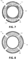
FIG. 6 to FIG. 8 each show a top view of alternative examples of a power transmission system according to embodiments of the present invention. - The figures are merely diagrammatic and not limitative. In the figures, dimensions of some parts may be exaggerated and not shown to scale for illustrative purposes.
- Reference numbers in the claims may not be interpreted as restricting the scope of protection. In the various figures, the same reference numbers refer to the same or equivalent elements.
- The present invention will be described in relation to particular embodiments and with reference to particular drawings; however, the invention is not restricted to these and is limited only by the claims. The drawings described are purely diagrammatic and not limitative. In the drawings, for illustrative purposes, the dimensions of some elements may be enlarged and not shown to scale. The dimensions and relative dimensions sometimes do not correlate with the actual practical implementation of the invention.
- Furthermore, the terms "first", "second", "third" and similar in the description and claims are used to distinguish similar elements and not necessarily to describe an order in either time or place, or in priority or in any other way. It should be understood that the terms used in this way are interchangeable under certain circumstances and that the embodiments of the invention described herein are suitable for working in a different sequence than described or shown here.
- In addition, the terms "top", "bottom", "above", "in front of" and similar in the description and claims are used for descriptive purposes and not necessarily to describe relative positions. It should be understood that the terms used in this way under certain circumstances may be mutually interchanged and that embodiments of the invention described here are also suitable for working in other orientations than described or shown here.
- It should be noted that the term "comprises" as used in the claims should not be interpreted as restricted to the means described thereafter; this term does not exclude other elements or steps. It should be interpreted as specifying the presence of the said features, values, steps or components to which reference is made, but does not exclude the presence or addition of one or more other features, values, steps or components or groups thereof. Thus the scope of the expression "a device comprising means A and B" should not be restricted to devices which consist only of components A and B. It means that in relation to the present invention, A and B are the only relevant components of the device.
- Reference throughout this specification to "one embodiment" or "an embodiment" means that a specific feature, structure or characteristic described in connection with the embodiment is included in at least one embodiment of the present invention. Thus the occurrence of the expressions "in one embodiment" or "in an embodiment" at various points throughout the specification need not necessarily refer to the same embodiment, but may well do so. Also, the specific features, structures or characteristics may be combined in any suitable manner as will be clear to the average person skilled in the art on the basis of this disclosure, in one or more embodiments.
- Similarly, it should be appreciated that in the description of exemplary embodiments of the invention, different features of the invention are sometimes grouped into a single embodiment, figure or description thereof, with the aim of streamlining the disclosure and assisting with the understanding of one or more of the various inventive aspects. This method of disclosure should also not be interpreted as a reflection of an intention that the invention requires more features than explicitly named in each claim. Furthermore, as the following claims indicate, inventive aspects lie in less than all features of any single previously disclosed embodiment. Thus the claims following the detailed description are hereby explicitly included in this detailed description, with each stand-alone claim as a separate embodiment of the invention.
- Also, while some embodiments described herein contain some but not other features included in other embodiments, combinations of features of different embodiments are considered as lying within the scope of the invention, and form different embodiments as will be understood by the person skilled in the art. For example, in the claims which follow, any of the embodiments described may be used in any arbitrary combination.
- In the description provided here, numerous specific details are highlighted. It should be understood that embodiments of the invention may be implemented without these specific details. In other cases, well-known methods, structures and techniques are not shown in detail in order to keep this description concise.
- In a first aspect, the present invention concerns a power transmission system for the transmission of electrical power to a sputter target in a sputter device. More specifically, it concerns the transmission of power in a sputter device in which a rotating sputter target is used. Such sputter targets are often rotationally symmetrical sputter targets such as cylindrical sputter targets. In such a sputter device, the sputter target is mounted on an endblock. The endblock has the function amongst others of rotating the sputter target and transmitting electrical power from a static part of the endblock to the dynamic part of the endblock on which the sputter target is mounted. The power transmission system is the means by which this transmission of electrical power is implemented. By way of illustration, the various elements of the power transmission system will be described with reference to
FIG. 1 , although embodiments are not restricted to this. Thepower transmission system 100 according to the present invention comprises afirst part 110 comprising acontact surface 115 which is positionable against afirst part 210 of anendblock 200 of the sputter device. It also comprises asecond part 120 which is inseparably connected to thefirst part 110 and athird part 130. It therefore also comprises athird part 130 comprising acontact surface 135 positionable against asecond part 220 of theendblock 200. According to the present invention, at least two of the threeparts power transmission system 100 are formed monolithically. Optionally, at least two of the three parts may be made of the same material. In addition, one of the threeparts power transmission system 100 is installed, thepower transmission system 100 is clamped between thefirst part 210 of theendblock 200 and thesecond part 220 of theendblock 200. In addition, this part is also responsible for the transmission of electrical power to the sputter target. This may avoid the need for separate wiring. The configuration is such that typically, one of theparts power transmission system 100 lies both against the dynamic part of theendblock 200 and against the static part of theendblock 200. In the first case, thepower transmission system 100 is static, while in the second case thepower transmission 100 moves with the dynamic part of the endblock. - Thus with reference to
FIG. 1 , although thefirst part 110 is shown as being the innermost part of thepower transmission system 100, which in this case is connected to the static part of theendblock 200, and thethird part 130 is shown as the outermost part of the power transmission system, which forms a slide contact against the dynamic part of theendblock 200, this is not strictly necessarily the case. The dynamic part of the endblock 200 (on which the target is mounted and which rotates) may be provided both centrally and on the outer edge of theendblock 200, and the slide contact provided for thepower transmission system 100 may be provided both against the dynamic and against the static part of theendblock 200. - In preferred embodiments of the present invention, as stated above, at least two of the three parts are made from the same material. In some cases, all parts of the
power transmission system 100 are made of the same material (possibly with an additional layer). The material may be a sprung material which at the same time is electrically conductive. In one example, this material may be a copper-beryllium alloy. In another embodiment, this material may be a copper-tin alloy. - In preferred embodiments of the present invention, at least two or all different parts of the power transmission system are made as one monolithic piece.
- In embodiments of the present invention, the
contact surface first part 110 and/or thethird part 130 which behaves as a slide contact is formed such that it has several contact regions with theendblock 200 when the sputter device is in the static state, i.e. when the sputter target is not rotating. Thecontact surface - In some embodiments, the slide contact is provided with an additional layer. This layer may for example be renewable after wear. This additional layer may be attached to the power transmission system by means of thermal bonding, although embodiments are not restricted to this. Such an additional layer may for example be selected such that it has a lubricating function. It may for example be made from an alloy which comprises tin and copper, or from an alloy which comprises copper or carbon.
- The left-hand side in
FIG. 1 shows part of anendblock 200 in which thepower transmission system 100 is positioned. - By way of illustration, although embodiments of the present invention are not limited to this, various specific examples of power transmission systems are discussed in relation to
FIG. 2 to FIG. 8 . -
FIG. 2 illustrates another example of a power transmission system 100 (right) and an endblock 200 (left) in which such apower transmission system 100 is installed. Thepower transmission system 100 in the present example has asecond part 120 in the form of a helical spring. This supplies the necessary spring force to press thefirst part 110 and thethird part 130 against the static part and the dynamic part of the endblock. Since in the present example all three of the elements are electrically conductive, the power can be transmitted via this powertransmission J system 100. -
FIG. 3 illustrates an alternative example in which again afirst part 110, asecond part 120 and athird part 130 of thepower transmission system 100 are shown. The second part again provides the necessary spring force for pressing thefirst part 110 and thethird part 130 against the static and dynamic part of the endblock. The contact surface from thethird part 130 takes the form of a meander which ensures a large contact surface for power transmission. -
FIG. 4 shows a further alternative example which uses an ondular spring. In this example, an axial force is exerted rather than a radial force. In embodiments not forming part of the present invention, a system may also be used in which a radial force is exerted in order to clamp the power transmission system. Such an embodiment may for example result from the embodiment inFIG. 4 by changing the oblique side, shown on the left of the figure, so that it stands perpendicular to the axis, whereby a radial force is exerted by the spring system. -
FIG. 5 illustrates a further alternative in which the power transmission system comprises a spring element with a spongy structure. This spring element also provides a spring force, whereby the power transmission system presses on one side against the static part and on the other side against the dynamic part of the endblock. -
FIG. 6 to FIG. 8 illustrate further examples of power transmission systems in which the second part is a spring element. The spring force of this spring element is obtained by the specific form in which the material is folded, in combination with the material used. It is an advantage of some embodiments of the present invention that a large contact area can be obtained between the power transmission system and the endblock. -
FIG. 6 andFIG. 7 also show anadditional layer 140 positioned on the third element. Such a layer may improve the electrical contact between the power transmission system and the endblock. - In another aspect, the present invention also concerns an endblock which comprises a power transmission system as described above. Features and advantages of the sputter device correspond to features and advantages of the power transmission system as described above.
- In a further aspect, the present invention also concerns a sputter device which comprises an endblock as described above. Features and advantages of the sputter device correspond to features and advantages of the endblock as described above. The invention is defined by the claims.
Claims (15)
- Power transmission system (100) for transmission of electrical power to a sputter target in a sputter device, the power transmission system comprising:- a first part (110) comprising a contact surface (115) positionable against a first part of a endblock of the sputter device,- a second part (120), wherein the first part (110) is inseparably connected to the second part (120) and the second part (120) is inseparably connected to a third part (130),- a third part (130) comprising a contact surface (135) positionable against a second part of the endblock,wherein at least two of the three parts are formed as one monolithic piece, and
wherein the first (110) and/or the second (120) and/or the third part (130) is a spring part such that, when mounted, the power transmission system is clamped between the first part of the endblock and the second part of the endblock, and wherein this spring part of the power transmission system is also responsible for the transmission of electrical power. - Power transmission system (100) according to claim 1, wherein at least two of the three parts of the power transmission system are made from the same material.
- Power transmission system (100) according to any of the previous claims, wherein the three parts (110, 120, 130) of the power transmission system are made as one monolithic part.
- Power transmission system (100) according to any of the preceding claims, wherein the spring part is from an electrically conductive material.
- Power transmission system (100) according to any of the preceding claims, wherein the contact surface (115) of the first part (110) of the power transmission system (100) is adapted to form a slide contact with the endblock or
wherein the contact surface (135) of the third part of the power transmission system (100) is adapted to form a slide contact with the endblock. - Power transmission system according to any of the preceding claims, wherein the first part of the endblock is rotatable in order to rotate the sputter target during a sputter operation or wherein the second part of the endblock is rotatable in order to rotate the sputter target during a sputter operation.
- Power transmission system (100) according to any of the preceding claims, wherein the contact surface (115, 135) of the first part (110) and/or the third part (130) of the power transmission system is formed such that there are several contact areas between the contact surface (115, 135) and the endblock, distributed over the respective contact surface (115, 135), when the sputter device is in the static state.
- Power transmission system (100) according to any of the preceding claims, wherein the second part of the power transmission system is the spring and electrically conductive part and/or wherein the power transmission system (100), when mounted in a endblock and the corresponding sputter installation is in operation, is positioned in cooling water and/or wherein the first part of the power transmission system has a cylindrical form adapted to adjoin to the first part of the endblock, and/or wherein the third part of the power transmission system has a cylindrical form adapted to adjoin the second part of the endblock or the inside of a cylindrical target.
- Power transmission system (100) according to any of the preceding claims, wherein at least the spring part is made of a copper-beryllium or copper-tin alloy.
- Power transmission system (100) according to any of the preceding claims, wherein an additional layer is present on the contact surface of the first and/or third part and
wherein the additional layer is renewable after wear and/or wherein the additional layer is thermally attached to the core and/or wherein the additional layer is made of an alloy which contains tin and copper, or an alloy which contains copper or carbon. - Power transmission system (100) according to any of the preceding claims, wherein the first part or the third part of the power transmission system comprises cylindrical elements, wherein the surfaces of the cylindrical elements are chromed and are formed such that they conform respectively to the first part of the endblock or the second part of the endblock or the sputter target, and wherein the cylindrical elements can be pressed radially against the second part of the endblock by the spring part and/or wherein the second part of the power transmission system comprises one or more helical springs.
- Power transmission system (100) according to claims 1 to 10, wherein the first part and/or the third part of the power transmission system may have a sprung cylindrical form or
wherein the first and/or the third part of the power transmission system consists of a meandering plate placed in a cylindrical surface or
wherein the first part and/or the third part of the power transmission system is formed as a spongy electrically conductive structure. - Power transmission system (100) according to any of claims 1 to 9, wherein the power transmission system is formed such that the third part of the power transmission system is pressed axially against the edge of the second part of the endblock, wherein the second part of the endblock is adapted to rotate the sputter target.
- Endblock for a sputter device which comprises a power transmission system (100) according to any of claims 1 to 13.
- Sputter device which comprises a power transmission system (100) according to any of claims 1 to 13.
Applications Claiming Priority (2)
| Application Number | Priority Date | Filing Date | Title |
|---|---|---|---|
| BE2016/5584A BE1023876B1 (en) | 2016-07-13 | 2016-07-13 | Electric transfer in an end block |
| PCT/IB2017/053895 WO2018011662A1 (en) | 2016-07-13 | 2017-06-29 | Electrical transfer in an endblock for a sputter device |
Publications (2)
| Publication Number | Publication Date |
|---|---|
| EP3485503A1 EP3485503A1 (en) | 2019-05-22 |
| EP3485503B1 true EP3485503B1 (en) | 2020-08-05 |
Family
ID=56611173
Family Applications (1)
| Application Number | Title | Priority Date | Filing Date |
|---|---|---|---|
| EP17749217.0A Active EP3485503B1 (en) | 2016-07-13 | 2017-06-29 | Electrical transmission in an endblock for a sputter device |
Country Status (5)
| Country | Link |
|---|---|
| US (1) | US11367596B2 (en) |
| EP (1) | EP3485503B1 (en) |
| CN (1) | CN109417015A (en) |
| BE (1) | BE1023876B1 (en) |
| WO (1) | WO2018011662A1 (en) |
Families Citing this family (2)
| Publication number | Priority date | Publication date | Assignee | Title |
|---|---|---|---|---|
| JP7303393B2 (en) * | 2020-09-16 | 2023-07-04 | 株式会社アルバック | Drive block for rotating cathode unit |
| DE102024108430A1 (en) * | 2024-03-25 | 2025-09-25 | VON ARDENNE Asset GmbH & Co. KG | End block and end block housing insert |
Family Cites Families (12)
| Publication number | Priority date | Publication date | Assignee | Title |
|---|---|---|---|---|
| US5096562A (en) | 1989-11-08 | 1992-03-17 | The Boc Group, Inc. | Rotating cylindrical magnetron structure for large area coating |
| US5200049A (en) | 1990-08-10 | 1993-04-06 | Viratec Thin Films, Inc. | Cantilever mount for rotating cylindrical magnetrons |
| US5620577A (en) | 1993-12-30 | 1997-04-15 | Viratec Thin Films, Inc. | Spring-loaded mount for a rotatable sputtering cathode |
| US5445721A (en) | 1994-08-25 | 1995-08-29 | The Boc Group, Inc. | Rotatable magnetron including a replacement target structure |
| US7399385B2 (en) * | 2001-06-14 | 2008-07-15 | Tru Vue, Inc. | Alternating current rotatable sputter cathode |
| US6736948B2 (en) * | 2002-01-18 | 2004-05-18 | Von Ardenne Anlagentechnik Gmbh | Cylindrical AC/DC magnetron with compliant drive system and improved electrical and thermal isolation |
| JP4836956B2 (en) | 2004-10-18 | 2011-12-14 | ベーカート・アドヴァンスト・コーティングス | End block for rotatable target sputtering equipment |
| CN2808932Y (en) | 2005-03-14 | 2006-08-23 | 深圳南玻南星玻璃加工有限公司 | High power sputtering film coating source |
| US20140021044A1 (en) * | 2006-10-02 | 2014-01-23 | Thermal Conductive Bonding, Inc. | Elastomer Bonded Rotary Sputtering Target |
| CA2791288A1 (en) | 2010-03-31 | 2011-10-06 | Mustang Vacuum Systems, Llc | Cylindrical rotating magnetron sputtering cathode device and method of depositing material using radio frequency emissions |
| DE102014104642B4 (en) | 2014-04-02 | 2018-11-15 | VON ARDENNE Asset GmbH & Co. KG | End block arrangement and processing arrangement |
| WO2016033475A1 (en) | 2014-08-29 | 2016-03-03 | Sputtering Components, Inc. | Dual power feed rotary sputtering cathode |
-
2016
- 2016-07-13 BE BE2016/5584A patent/BE1023876B1/en not_active IP Right Cessation
-
2017
- 2017-06-29 CN CN201780042651.9A patent/CN109417015A/en active Pending
- 2017-06-29 EP EP17749217.0A patent/EP3485503B1/en active Active
- 2017-06-29 US US16/316,841 patent/US11367596B2/en active Active
- 2017-06-29 WO PCT/IB2017/053895 patent/WO2018011662A1/en not_active Ceased
Non-Patent Citations (1)
| Title |
|---|
| None * |
Also Published As
| Publication number | Publication date |
|---|---|
| BE1023876B1 (en) | 2017-08-31 |
| CN109417015A (en) | 2019-03-01 |
| US11367596B2 (en) | 2022-06-21 |
| EP3485503A1 (en) | 2019-05-22 |
| US20190237306A1 (en) | 2019-08-01 |
| WO2018011662A1 (en) | 2018-01-18 |
Similar Documents
| Publication | Publication Date | Title |
|---|---|---|
| EP3552276B1 (en) | High current and rpm-capable slip ring assembly | |
| JP6163480B2 (en) | Current shunt ring | |
| US20140252922A1 (en) | Electrical machines such as generators and motors | |
| US20060231394A1 (en) | Cylindrical AC/DC Magnetron with Compliant Drive System and Improved Electrical and Thermal Isolation | |
| US11367596B2 (en) | Electrical transfer in an endblock for a sputter device | |
| JP2017503923A (en) | Physical vapor deposition (PVD) target with low friction pad | |
| JP2018518044A5 (en) | ||
| RU2665059C2 (en) | Spraying target having the increased energy compatibility | |
| US20170339752A1 (en) | Eddy current heat generating apparatus | |
| US10544844B2 (en) | Plate assemblies including floating wear linings for multi-disk brake systems and methods for reducing vibration in a multi-disk brake system | |
| JP5529152B2 (en) | X-ray tube with rotatable anode and liquid heat sink | |
| EP4202968A3 (en) | X-ray cathode focusing element | |
| EP3490107B1 (en) | Generator stators and methods of making generator stators | |
| IL290856B1 (en) | Electric motor assembly rotating in the opposite direction | |
| CN106574656B (en) | Rotor bearing temperature sensor | |
| JP7346107B2 (en) | Bearing device and spindle device | |
| EP3187741B1 (en) | Bearing liners for use within light alloy housings | |
| CN110285144B (en) | Rotating anode bearing for an X-ray tube and rotating anode for an X-ray tube | |
| DE102014104642B4 (en) | End block arrangement and processing arrangement | |
| US20130285496A1 (en) | Miniature Motor and Bearing Arrangement | |
| US11025134B2 (en) | Motor and ducted fan having heat radiation portions for cooling magnets | |
| TW201826348A (en) | A universally mountable end-block | |
| US11008904B2 (en) | Camshaft phaser cover element and camshaft phaser | |
| US9957608B2 (en) | Composite shielding | |
| JP2004278570A (en) | Cooling mechanism for bearing device |
Legal Events
| Date | Code | Title | Description |
|---|---|---|---|
| STAA | Information on the status of an ep patent application or granted ep patent |
Free format text: STATUS: UNKNOWN |
|
| STAA | Information on the status of an ep patent application or granted ep patent |
Free format text: STATUS: THE INTERNATIONAL PUBLICATION HAS BEEN MADE |
|
| PUAI | Public reference made under article 153(3) epc to a published international application that has entered the european phase |
Free format text: ORIGINAL CODE: 0009012 |
|
| STAA | Information on the status of an ep patent application or granted ep patent |
Free format text: STATUS: REQUEST FOR EXAMINATION WAS MADE |
|
| 17P | Request for examination filed |
Effective date: 20190131 |
|
| AK | Designated contracting states |
Kind code of ref document: A1 Designated state(s): AL AT BE BG CH CY CZ DE DK EE ES FI FR GB GR HR HU IE IS IT LI LT LU LV MC MK MT NL NO PL PT RO RS SE SI SK SM TR |
|
| AX | Request for extension of the european patent |
Extension state: BA ME |
|
| DAV | Request for validation of the european patent (deleted) | ||
| DAX | Request for extension of the european patent (deleted) | ||
| GRAP | Despatch of communication of intention to grant a patent |
Free format text: ORIGINAL CODE: EPIDOSNIGR1 |
|
| STAA | Information on the status of an ep patent application or granted ep patent |
Free format text: STATUS: GRANT OF PATENT IS INTENDED |
|
| INTG | Intention to grant announced |
Effective date: 20200220 |
|
| GRAS | Grant fee paid |
Free format text: ORIGINAL CODE: EPIDOSNIGR3 |
|
| GRAA | (expected) grant |
Free format text: ORIGINAL CODE: 0009210 |
|
| STAA | Information on the status of an ep patent application or granted ep patent |
Free format text: STATUS: THE PATENT HAS BEEN GRANTED |
|
| RAP1 | Party data changed (applicant data changed or rights of an application transferred) |
Owner name: SOLERAS ADVANCED COATINGS BV |
|
| AK | Designated contracting states |
Kind code of ref document: B1 Designated state(s): AL AT BE BG CH CY CZ DE DK EE ES FI FR GB GR HR HU IE IS IT LI LT LU LV MC MK MT NL NO PL PT RO RS SE SI SK SM TR |
|
| REG | Reference to a national code |
Ref country code: GB Ref legal event code: FG4D |
|
| REG | Reference to a national code |
Ref country code: CH Ref legal event code: EP |
|
| REG | Reference to a national code |
Ref country code: AT Ref legal event code: REF Ref document number: 1299892 Country of ref document: AT Kind code of ref document: T Effective date: 20200815 |
|
| REG | Reference to a national code |
Ref country code: DE Ref legal event code: R096 Ref document number: 602017021166 Country of ref document: DE |
|
| REG | Reference to a national code |
Ref country code: IE Ref legal event code: FG4D |
|
| REG | Reference to a national code |
Ref country code: LT Ref legal event code: MG4D |
|
| REG | Reference to a national code |
Ref country code: NL Ref legal event code: MP Effective date: 20200805 |
|
| REG | Reference to a national code |
Ref country code: AT Ref legal event code: MK05 Ref document number: 1299892 Country of ref document: AT Kind code of ref document: T Effective date: 20200805 |
|
| PG25 | Lapsed in a contracting state [announced via postgrant information from national office to epo] |
Ref country code: ES Free format text: LAPSE BECAUSE OF FAILURE TO SUBMIT A TRANSLATION OF THE DESCRIPTION OR TO PAY THE FEE WITHIN THE PRESCRIBED TIME-LIMIT Effective date: 20200805 Ref country code: PT Free format text: LAPSE BECAUSE OF FAILURE TO SUBMIT A TRANSLATION OF THE DESCRIPTION OR TO PAY THE FEE WITHIN THE PRESCRIBED TIME-LIMIT Effective date: 20201207 Ref country code: LT Free format text: LAPSE BECAUSE OF FAILURE TO SUBMIT A TRANSLATION OF THE DESCRIPTION OR TO PAY THE FEE WITHIN THE PRESCRIBED TIME-LIMIT Effective date: 20200805 Ref country code: HR Free format text: LAPSE BECAUSE OF FAILURE TO SUBMIT A TRANSLATION OF THE DESCRIPTION OR TO PAY THE FEE WITHIN THE PRESCRIBED TIME-LIMIT Effective date: 20200805 Ref country code: BG Free format text: LAPSE BECAUSE OF FAILURE TO SUBMIT A TRANSLATION OF THE DESCRIPTION OR TO PAY THE FEE WITHIN THE PRESCRIBED TIME-LIMIT Effective date: 20201105 Ref country code: SE Free format text: LAPSE BECAUSE OF FAILURE TO SUBMIT A TRANSLATION OF THE DESCRIPTION OR TO PAY THE FEE WITHIN THE PRESCRIBED TIME-LIMIT Effective date: 20200805 Ref country code: NO Free format text: LAPSE BECAUSE OF FAILURE TO SUBMIT A TRANSLATION OF THE DESCRIPTION OR TO PAY THE FEE WITHIN THE PRESCRIBED TIME-LIMIT Effective date: 20201105 Ref country code: GR Free format text: LAPSE BECAUSE OF FAILURE TO SUBMIT A TRANSLATION OF THE DESCRIPTION OR TO PAY THE FEE WITHIN THE PRESCRIBED TIME-LIMIT Effective date: 20201106 Ref country code: FI Free format text: LAPSE BECAUSE OF FAILURE TO SUBMIT A TRANSLATION OF THE DESCRIPTION OR TO PAY THE FEE WITHIN THE PRESCRIBED TIME-LIMIT Effective date: 20200805 Ref country code: AT Free format text: LAPSE BECAUSE OF FAILURE TO SUBMIT A TRANSLATION OF THE DESCRIPTION OR TO PAY THE FEE WITHIN THE PRESCRIBED TIME-LIMIT Effective date: 20200805 |
|
| PG25 | Lapsed in a contracting state [announced via postgrant information from national office to epo] |
Ref country code: RS Free format text: LAPSE BECAUSE OF FAILURE TO SUBMIT A TRANSLATION OF THE DESCRIPTION OR TO PAY THE FEE WITHIN THE PRESCRIBED TIME-LIMIT Effective date: 20200805 Ref country code: NL Free format text: LAPSE BECAUSE OF FAILURE TO SUBMIT A TRANSLATION OF THE DESCRIPTION OR TO PAY THE FEE WITHIN THE PRESCRIBED TIME-LIMIT Effective date: 20200805 Ref country code: PL Free format text: LAPSE BECAUSE OF FAILURE TO SUBMIT A TRANSLATION OF THE DESCRIPTION OR TO PAY THE FEE WITHIN THE PRESCRIBED TIME-LIMIT Effective date: 20200805 Ref country code: LV Free format text: LAPSE BECAUSE OF FAILURE TO SUBMIT A TRANSLATION OF THE DESCRIPTION OR TO PAY THE FEE WITHIN THE PRESCRIBED TIME-LIMIT Effective date: 20200805 Ref country code: IS Free format text: LAPSE BECAUSE OF FAILURE TO SUBMIT A TRANSLATION OF THE DESCRIPTION OR TO PAY THE FEE WITHIN THE PRESCRIBED TIME-LIMIT Effective date: 20201205 |
|
| PG25 | Lapsed in a contracting state [announced via postgrant information from national office to epo] |
Ref country code: CZ Free format text: LAPSE BECAUSE OF FAILURE TO SUBMIT A TRANSLATION OF THE DESCRIPTION OR TO PAY THE FEE WITHIN THE PRESCRIBED TIME-LIMIT Effective date: 20200805 Ref country code: DK Free format text: LAPSE BECAUSE OF FAILURE TO SUBMIT A TRANSLATION OF THE DESCRIPTION OR TO PAY THE FEE WITHIN THE PRESCRIBED TIME-LIMIT Effective date: 20200805 Ref country code: RO Free format text: LAPSE BECAUSE OF FAILURE TO SUBMIT A TRANSLATION OF THE DESCRIPTION OR TO PAY THE FEE WITHIN THE PRESCRIBED TIME-LIMIT Effective date: 20200805 Ref country code: EE Free format text: LAPSE BECAUSE OF FAILURE TO SUBMIT A TRANSLATION OF THE DESCRIPTION OR TO PAY THE FEE WITHIN THE PRESCRIBED TIME-LIMIT Effective date: 20200805 Ref country code: SM Free format text: LAPSE BECAUSE OF FAILURE TO SUBMIT A TRANSLATION OF THE DESCRIPTION OR TO PAY THE FEE WITHIN THE PRESCRIBED TIME-LIMIT Effective date: 20200805 |
|
| REG | Reference to a national code |
Ref country code: DE Ref legal event code: R097 Ref document number: 602017021166 Country of ref document: DE |
|
| PG25 | Lapsed in a contracting state [announced via postgrant information from national office to epo] |
Ref country code: AL Free format text: LAPSE BECAUSE OF FAILURE TO SUBMIT A TRANSLATION OF THE DESCRIPTION OR TO PAY THE FEE WITHIN THE PRESCRIBED TIME-LIMIT Effective date: 20200805 |
|
| PLBE | No opposition filed within time limit |
Free format text: ORIGINAL CODE: 0009261 |
|
| STAA | Information on the status of an ep patent application or granted ep patent |
Free format text: STATUS: NO OPPOSITION FILED WITHIN TIME LIMIT |
|
| PG25 | Lapsed in a contracting state [announced via postgrant information from national office to epo] |
Ref country code: SK Free format text: LAPSE BECAUSE OF FAILURE TO SUBMIT A TRANSLATION OF THE DESCRIPTION OR TO PAY THE FEE WITHIN THE PRESCRIBED TIME-LIMIT Effective date: 20200805 |
|
| 26N | No opposition filed |
Effective date: 20210507 |
|
| PG25 | Lapsed in a contracting state [announced via postgrant information from national office to epo] |
Ref country code: IT Free format text: LAPSE BECAUSE OF FAILURE TO SUBMIT A TRANSLATION OF THE DESCRIPTION OR TO PAY THE FEE WITHIN THE PRESCRIBED TIME-LIMIT Effective date: 20200805 |
|
| PG25 | Lapsed in a contracting state [announced via postgrant information from national office to epo] |
Ref country code: SI Free format text: LAPSE BECAUSE OF FAILURE TO SUBMIT A TRANSLATION OF THE DESCRIPTION OR TO PAY THE FEE WITHIN THE PRESCRIBED TIME-LIMIT Effective date: 20200805 |
|
| PG25 | Lapsed in a contracting state [announced via postgrant information from national office to epo] |
Ref country code: MC Free format text: LAPSE BECAUSE OF FAILURE TO SUBMIT A TRANSLATION OF THE DESCRIPTION OR TO PAY THE FEE WITHIN THE PRESCRIBED TIME-LIMIT Effective date: 20200805 |
|
| REG | Reference to a national code |
Ref country code: CH Ref legal event code: PL |
|
| PG25 | Lapsed in a contracting state [announced via postgrant information from national office to epo] |
Ref country code: LI Free format text: LAPSE BECAUSE OF NON-PAYMENT OF DUE FEES Effective date: 20210630 Ref country code: IE Free format text: LAPSE BECAUSE OF NON-PAYMENT OF DUE FEES Effective date: 20210629 Ref country code: CH Free format text: LAPSE BECAUSE OF NON-PAYMENT OF DUE FEES Effective date: 20210630 |
|
| PG25 | Lapsed in a contracting state [announced via postgrant information from national office to epo] |
Ref country code: CY Free format text: LAPSE BECAUSE OF FAILURE TO SUBMIT A TRANSLATION OF THE DESCRIPTION OR TO PAY THE FEE WITHIN THE PRESCRIBED TIME-LIMIT Effective date: 20200805 |
|
| PG25 | Lapsed in a contracting state [announced via postgrant information from national office to epo] |
Ref country code: HU Free format text: LAPSE BECAUSE OF FAILURE TO SUBMIT A TRANSLATION OF THE DESCRIPTION OR TO PAY THE FEE WITHIN THE PRESCRIBED TIME-LIMIT; INVALID AB INITIO Effective date: 20170629 |
|
| PG25 | Lapsed in a contracting state [announced via postgrant information from national office to epo] |
Ref country code: MK Free format text: LAPSE BECAUSE OF FAILURE TO SUBMIT A TRANSLATION OF THE DESCRIPTION OR TO PAY THE FEE WITHIN THE PRESCRIBED TIME-LIMIT Effective date: 20200805 |
|
| PG25 | Lapsed in a contracting state [announced via postgrant information from national office to epo] |
Ref country code: TR Free format text: LAPSE BECAUSE OF NON-PAYMENT OF DUE FEES Effective date: 20210629 Ref country code: MT Free format text: LAPSE BECAUSE OF FAILURE TO SUBMIT A TRANSLATION OF THE DESCRIPTION OR TO PAY THE FEE WITHIN THE PRESCRIBED TIME-LIMIT Effective date: 20200805 |
|
| PGFP | Annual fee paid to national office [announced via postgrant information from national office to epo] |
Ref country code: DE Payment date: 20250618 Year of fee payment: 9 |
|
| PGFP | Annual fee paid to national office [announced via postgrant information from national office to epo] |
Ref country code: GB Payment date: 20250618 Year of fee payment: 9 |
|
| PGFP | Annual fee paid to national office [announced via postgrant information from national office to epo] |
Ref country code: LU Payment date: 20250627 Year of fee payment: 9 Ref country code: BE Payment date: 20250618 Year of fee payment: 9 |
|
| PGFP | Annual fee paid to national office [announced via postgrant information from national office to epo] |
Ref country code: FR Payment date: 20250625 Year of fee payment: 9 |