EP3484809B1 - Sicherungskopfplatte für einstellbaren sattelbaum eines reitsattels und sattelbaum mit solch einer kopfplatte - Google Patents
Sicherungskopfplatte für einstellbaren sattelbaum eines reitsattels und sattelbaum mit solch einer kopfplatte Download PDFInfo
- Publication number
- EP3484809B1 EP3484809B1 EP17808136.0A EP17808136A EP3484809B1 EP 3484809 B1 EP3484809 B1 EP 3484809B1 EP 17808136 A EP17808136 A EP 17808136A EP 3484809 B1 EP3484809 B1 EP 3484809B1
- Authority
- EP
- European Patent Office
- Prior art keywords
- saddle tree
- headplate
- saddle
- rotation
- tree according
- Prior art date
- Legal status (The legal status is an assumption and is not a legal conclusion. Google has not performed a legal analysis and makes no representation as to the accuracy of the status listed.)
- Active
Links
Images


Classifications
-
- B—PERFORMING OPERATIONS; TRANSPORTING
- B68—SADDLERY; UPHOLSTERY
- B68C—SADDLES; STIRRUPS
- B68C1/00—Saddling equipment for riding- or pack-animals
- B68C1/02—Saddles
- B68C1/04—Adjustable saddles
-
- B—PERFORMING OPERATIONS; TRANSPORTING
- B68—SADDLERY; UPHOLSTERY
- B68C—SADDLES; STIRRUPS
- B68C1/00—Saddling equipment for riding- or pack-animals
- B68C1/02—Saddles
- B68C1/025—Saddle-trees
-
- B—PERFORMING OPERATIONS; TRANSPORTING
- B68—SADDLERY; UPHOLSTERY
- B68C—SADDLES; STIRRUPS
- B68C1/00—Saddling equipment for riding- or pack-animals
- B68C1/02—Saddles
- B68C1/04—Adjustable saddles
- B68C2001/046—Adjustable saddles by means of discrete pre-set positions
Definitions
- the present invention relates to the field of riding accessories and relates to a locking headplate for a saddle tree of a riding saddle and to a saddle tree comprising such a headplate.
- riding saddles are made on a substantially rigid frame, known as "saddle tree”.
- the saddle tree gives shape to the saddle and should follow the shape of the back of the horse as much as possible.
- the saddle tree has a front portion leaning on the withers of the horse.
- This front portion has, when viewed from the front, an inverted "V" shape. That is, the front portion comprises two lateral portions to which the abutments for the straps surrounding the horse's body are fixed.
- the object of the present invention is to propose a saddle tree comprising a locking headplate that is more reliable than the known adjustment mechanisms and suitable to be operated also with the rider already on the saddle, allowing verification of the desired adjustment.
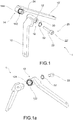
- reference numeral 1 indicates as a whole a locking headplate suitable for varying the configuration of a saddle tree.
- the headplate allows adjusting the opening of the front side portions 102 of a saddle tree 100.
- Headplate 1 comprises two rigid headplate arms 10, 10', each adapted to be fixed to the inner side of a respective front side portion 102 of the saddle tree 100.
- the two headplate arms 10, 10' have mutual connection end portions 12, 14 which form a headplate hinge 16 for a rotation of one headplate arm with respect to the other about an axis of rotation X.
- the end portions 12, 14 are further fitted with facing blocking surfaces 122, 142 shaped in a complementary manner so as to block, when placed in mutual contact, the rotation of the headplate arms 10, 10'.
- Headplate 1 is further provided with arm translation means 20 operable to translate one arm 10 with respect to the other arm 10' along the axis of rotation X so as to cause the engagement and disengagement of the facing blocking surfaces 122, 142.
- the arms translation means 20 are accessible through a front access opening 30 coaxial to the axis of rotation X.
- front it is meant that, when headplate 1 is assembled on the saddle tree 100, such access opening 30 is facing towards the front end of the saddle tree 100.
- an end portion 12 comprises a hollow tubular element 124; the other end portion 14 comprises a pin 144 which is inserted in such a hollow tubular element 124.
- a blocking surface 122 is formed in the annular end surface of the hollow tubular element 124, facing towards the other end portion 14.
- the other blocking surface 142 is formed in an annular wall surrounding the base of pin 144 and which, when pin 144 is fully inserted into the hollow tubular element 124, abuts against the end surface of the hollow tubular element 124.
- the blocking surfaces 122, 142 are serrated surfaces, i.e. they have a plurality of radial projections which alternate with radial valleys.
- the arms translation means 20 comprise a screw 22 housed without the possibility of axial translation in one of the end portions 12, 14.
- Screw 22 is screwed into a threaded hole 24 formed in the other one of the end portions 12, 14. Since screw 2 is locked axially, a rotation thereof necessarily causes an axial translation of the arm with respect to the other.
- screw 22 is housed in the end portion 12 comprising the hollow tubular element 124; the threaded hole 24 is made in pin 144 of the other end portion 14.
- screw 22 has a head 22' housed in the front access opening 30.
- the front access opening 30 is thus formed in the end portion 12 crossed by screw 22.
- the end portion 12 comprises a front portion 12' in which the front access opening 30 is formed and a rear access portion that forms the hollow tubular element 124.
- head 22' of screw 22 is axially blocked in the front access opening 30 by means of a seeger 32.
- An object of the present invention is also a saddle tree 100 provided with headplate 1 described above.
- the saddle tree 100 comprises a saddle tree body 101 having a front portion 101' adapted to abut on the withers of a horse.
- This front portion 101' comprises two side portions 102, inclined and converging upwardly.
- Each arm 10, 10' of headplate 1 is fixed to the inner side of a respective side portion 102 of the saddle tree.
- a recess 103 is formed which surrounds the end portions 12, 14 of the headplate arms.
- the front access opening 30 is located substantially aligned with the upper surface of the saddle tree 100, thus in a portion such that it is possible to actuate the arm translation means 20 also while sitting on the saddle, exploiting the space between the front end and of the saddle tree and the horse's neck.
- headplate 1 is fixed to the saddle tree 100 only by means of arms 10, 10'.
- At least the front portion 101' of the saddle tree body 101 is made of a material and/or of a thickness such as to allow a further divergence of the side portions 102 with respect to the inclination at rest of said side portions 102, under the action of a pressure exerted thereon.
- such a front portion 101' of the saddle tree is made of a plastic material.
- exerting a force from above downwards on the saddle tree 100 causes an opening of the side portions 102 of the saddle tree 100 when these are resting on a supporting surface or when the saddle tree 100 is positioned on the back of the horse.
- the side portions 102 of the saddle tree 100 are hinged together.
- the adjustment system of the saddle tree configuration exploits the ability of the saddle tree itself to vary the inclination of the front side portions 102 when it is subjected to a pressure.
- the locking headplate 1 thus has a particularly simple structure, formed by a reduced number of components, and therefore particularly reliable and safe.
- the headplate of the saddle tree allows carrying out a fine adjustment of the saddle tree configuration.
- this adjustment can be carried out while sitting on the saddle, and thus identifying the best configuration of the saddle tree directly adapting it to the size and conformation of the horse.
- the same weight of the rider facilitates the adjustment and the balance of the saddle on the horse's back, distributing the resulting weight and pressure in a uniform manner for optimal comfort of the horse and rider.
Landscapes
- Engineering & Computer Science (AREA)
- Mechanical Engineering (AREA)
- Supports For Plants (AREA)
- Protection Of Plants (AREA)
Claims (8)
- Sattelbaum, umfassend einen Sattelbaumkörper (101) mit einem vorderen Abschnitt, der geeignet ist, an den Widerrist eines Pferdes anzuliegen, wobei der vordere Abschnitt zwei geneigte Seitenabschnitte (102) umfasst, die nach oben zusammenlaufen, wobei der Sattelbaum ferner eine Verriegelungskopfplatte (1) zum Einstellen der Konfiguration des Sattelbaums eines Reitersattels umfasst, wobei die Verriegelungskopfplatte zwei starre Kopfplattenarme (10, 10') umfasst, die jeweils an der Innenseite eines jeweiligen geneigten Seitenabschnitts des lateralen vorderen Abschnitts (102) des Sattelbaums befestigt sind, wobei die beiden Kopfplattenarme jeweils gegenseitige bzw. gemeinsame Verbindungsendabschnitte (12, 14) aufweisen, die ein Kopfplattenscharnier bzw. -gelenk (16) für eine Drehung eines Kopfplattenarms in Bezug auf den anderen um eine Drehachse (X) bilden, dadurch gekennzeichnet, dass die Endabschnitte ferner mit zugewandten Blockierflächen (122, 142) versehen sind, die komplementär geformt sind, um, wenn sie in gegenseitigem Kontakt platziert sind, die Drehung der Kopfplattenarme zu blockieren, wobei die Kopfplatte ferner mit Armverschiebungsmitteln (20) versehen, die dahingehend operabel sind, einen Arm in Bezug auf den anderen entlang der Drehachse zu verschieben, um den Eingriff und das Lösen der Blockierflächen zu bewirken, wobei die Armverschiebungsmittel durch eine vordere Zugangsöffnung (30) koaxial zu der Drehachse (X) zugänglich sind.
- Sattelbaum nach Anspruch 1, wobei ein Endabschnitt (12) ein hohles rohrförmiges Element (124) umfasst und wobei der andere Endabschnitt (14) einen Stift (144) umfasst, der in das hohle rohförmige Element eingesetzt ist.
- Sattelbaum nach Anspruch 1 oder 2, wobei die Armverschiebungsmittel eine Schraube (22), die ohne die Möglichkeit einer axialen Verschiebung in einem der Endabschnitte untergebracht ist, und ein Gewindeloch (24) umfassen, das in dem anderen Ende der Endabschnitte gemacht ist.
- Sattelbaum nach Anspruch 2 und 3, wobei die Schraube in dem Endabschnitt untergebracht ist, der das hohle rohrförmige Element umfasst, und wobei das Gewindeloch in dem Stift des anderen Endabschnitts gemacht ist.
- Sattelbaum nach Anspruch 3 oder 4, wobei der Kopf (22') der Schraube (22) in der vorderen Zugangsöffnung (30) untergebracht ist.
- Sattelbaum nach dem vorhergehenden Anspruch, wobei der Kopf der Schraube in der vorderen Zugangsöffnung mittels eines Seegers bzw. Schließrings (32) axial blockiert ist.
- Sattelbaum nach einem der vorhergehenden Ansprüche, wobei zumindest der vordere Abschnitt des Sattelbaumkörpers aus einem Material und/oder einer Dicke besteht, das bzw. die eine weitere Divergenz der Seitenabschnitte (102) in Bezug auf die Neigung im Ruhezustand der Seitenabschnitte unter der Einwirkung eines auf sie ausgeübten Drucks erlaubt.
- Sattelbaum nach einem der Ansprüche 1-6, wobei die Seitenabschnitte mittels Scharnier bzw. gelenkig miteinander verbunden sind.
Applications Claiming Priority (2)
| Application Number | Priority Date | Filing Date | Title |
|---|---|---|---|
| IT102016000074424A IT201600074424A1 (it) | 2016-07-15 | 2016-07-15 | Archetto di regolazione per un arcione di una sella di equitazione e arcione comprendente tale archetto |
| PCT/IB2017/054178 WO2018011712A2 (en) | 2016-07-15 | 2017-07-11 | Locking headplate for a saddle tree of a riding saddle and saddle tree comprising such a headplate |
Publications (2)
| Publication Number | Publication Date |
|---|---|
| EP3484809A2 EP3484809A2 (de) | 2019-05-22 |
| EP3484809B1 true EP3484809B1 (de) | 2020-11-18 |
Family
ID=57851129
Family Applications (1)
| Application Number | Title | Priority Date | Filing Date |
|---|---|---|---|
| EP17808136.0A Active EP3484809B1 (de) | 2016-07-15 | 2017-07-11 | Sicherungskopfplatte für einstellbaren sattelbaum eines reitsattels und sattelbaum mit solch einer kopfplatte |
Country Status (5)
| Country | Link |
|---|---|
| US (1) | US11299390B2 (de) |
| EP (1) | EP3484809B1 (de) |
| DK (1) | DK3484809T3 (de) |
| IT (1) | IT201600074424A1 (de) |
| WO (1) | WO2018011712A2 (de) |
Families Citing this family (4)
| Publication number | Priority date | Publication date | Assignee | Title |
|---|---|---|---|---|
| IT201900001639A1 (it) * | 2019-02-07 | 2020-08-07 | Epi Srl | Arcione in materiale composito per sella da equitazione e meccanismi di regolazione |
| US11377343B2 (en) * | 2020-07-18 | 2022-07-05 | Schleese Saddlery Service Ltd. | Adjustable gullet plate with interchangeable portions |
| IT202200010541A1 (it) * | 2022-05-20 | 2023-11-20 | Benetti Hub S R L | Arcione per selle da equitazione |
| US12420587B2 (en) * | 2023-09-29 | 2025-09-23 | Permobil, Inc. | Caster adjustment assembly for a wheelchair |
Citations (2)
| Publication number | Priority date | Publication date | Assignee | Title |
|---|---|---|---|---|
| WO2013021115A1 (fr) * | 2011-08-05 | 2013-02-14 | Merlin Michel | Armature reglable pour selle a monter sans necessite de demontage |
| EP2690056A1 (de) * | 2012-07-27 | 2014-01-29 | Intec Corporation | Sicherungskopfplatte für einstellbaren Sattelbaum |
Family Cites Families (12)
| Publication number | Priority date | Publication date | Assignee | Title |
|---|---|---|---|---|
| US38404A (en) * | 1863-05-05 | Improvement in saddles | ||
| FR15669E (fr) * | 1906-12-10 | 1912-08-30 | Karl Franz Schaller | Bat |
| GB191418567A (en) * | 1914-08-11 | 1915-08-11 | Patrick Douglas Stewart | Improvements in or relating to Saddles. |
| US1246675A (en) * | 1915-08-09 | 1917-11-13 | Patrick Douglas Stewart | Saddle. |
| US3388530A (en) * | 1966-01-28 | 1968-06-18 | Eugene F. Parker | Roping saddle horn assembly |
| US4473992A (en) * | 1982-12-13 | 1984-10-02 | Conger Iii William W | Adjustable saddle rigging |
| DE68900305D1 (de) * | 1988-02-11 | 1991-11-14 | Weller International Uk Ltd | Kammerbuegel und baum fuer sattel. |
| US20170297893A1 (en) * | 2009-03-16 | 2017-10-19 | Isidore Strauss | Locking adjustable headplate with motion restrictor for adjustable saddle tree |
| US8230666B2 (en) * | 2009-03-16 | 2012-07-31 | Intec Corporation | Locking headplate for adjustable saddle tree |
| DE202010010215U1 (de) * | 2010-07-13 | 2011-11-09 | Hkm Sports Equipment Gmbh | Reitsattel mit veränderlicher Kopfweite |
| DE202014105189U1 (de) * | 2014-05-20 | 2015-08-24 | Przedsiebiorstwo Produkcyjno-Handlowe "Akcesoria Jezdzieckie" Franciszek Pera | Kopfeisen für stufenlose Einstellung der Kammerweite |
| EP3239094B1 (de) * | 2016-04-27 | 2018-09-12 | Ikonic Saddlery | Sattel |
-
2016
- 2016-07-15 IT IT102016000074424A patent/IT201600074424A1/it unknown
-
2017
- 2017-07-11 US US16/310,001 patent/US11299390B2/en active Active
- 2017-07-11 EP EP17808136.0A patent/EP3484809B1/de active Active
- 2017-07-11 WO PCT/IB2017/054178 patent/WO2018011712A2/en not_active Ceased
- 2017-07-11 DK DK17808136.0T patent/DK3484809T3/da active
Patent Citations (2)
| Publication number | Priority date | Publication date | Assignee | Title |
|---|---|---|---|---|
| WO2013021115A1 (fr) * | 2011-08-05 | 2013-02-14 | Merlin Michel | Armature reglable pour selle a monter sans necessite de demontage |
| EP2690056A1 (de) * | 2012-07-27 | 2014-01-29 | Intec Corporation | Sicherungskopfplatte für einstellbaren Sattelbaum |
Also Published As
| Publication number | Publication date |
|---|---|
| US11299390B2 (en) | 2022-04-12 |
| US20200317503A1 (en) | 2020-10-08 |
| WO2018011712A2 (en) | 2018-01-18 |
| EP3484809A2 (de) | 2019-05-22 |
| IT201600074424A1 (it) | 2018-01-15 |
| DK3484809T3 (da) | 2021-02-15 |
| WO2018011712A3 (en) | 2018-03-01 |
Similar Documents
| Publication | Publication Date | Title |
|---|---|---|
| EP3484809B1 (de) | Sicherungskopfplatte für einstellbaren sattelbaum eines reitsattels und sattelbaum mit solch einer kopfplatte | |
| US10583882B2 (en) | Bicycle seat attachment assembly | |
| EP3154848B1 (de) | Fahrradsitz und schlossanordnung | |
| CA2258319A1 (en) | Adjustable gauge wheel support structure | |
| US20090007720A1 (en) | Protection guard for vehicle handlebar | |
| CA2203193C (en) | Seat support for office chairs or the like | |
| US20030189311A1 (en) | Adjustable connection device for connecting parts of wheel chairs | |
| CA2712740C (en) | Locking headplate for adjustable saddle tree | |
| US11970386B2 (en) | Equestrian stirrup with releasable foot retention | |
| GB2423230A (en) | Adjustable saddle tree | |
| US10450020B2 (en) | Bicycle seat assembly | |
| EP2336080B1 (de) | Sicherungskopfplatte für einstellbaren Sattelbaum | |
| US5651240A (en) | Saddle handle | |
| US1062327A (en) | Stirrup. | |
| EP3069969B1 (de) | Sattelstützeneinheit, die ein oder zwei vorbestimmte sitzhöhen bestimmt | |
| EP3434572B1 (de) | Verstellbare fahrradlenkervorbauanordnung | |
| EP4279443A1 (de) | Sattelbaum für einen pferdesattel | |
| FR3050194B1 (fr) | Etrier d'equitation de securite | |
| US20170297893A1 (en) | Locking adjustable headplate with motion restrictor for adjustable saddle tree | |
| FR3027892A1 (fr) | Systeme amovible facilitant le reglage d'un etrier de bete de selle | |
| US20080289445A1 (en) | Racing Bicycle Pedal Assembly having Lighter Weight | |
| US9783260B2 (en) | Adjustable rear wheel hood brake/stop system for free style kick scooters | |
| EP2016021A1 (de) | Steigbügel mit komplettstützboden für die füsse des reiters | |
| US1262905A (en) | Extension-crutch. | |
| US20050027371A1 (en) | Artificial limb with relative position-adjustable upper and lower limb parts |
Legal Events
| Date | Code | Title | Description |
|---|---|---|---|
| STAA | Information on the status of an ep patent application or granted ep patent |
Free format text: STATUS: UNKNOWN |
|
| STAA | Information on the status of an ep patent application or granted ep patent |
Free format text: STATUS: THE INTERNATIONAL PUBLICATION HAS BEEN MADE |
|
| PUAI | Public reference made under article 153(3) epc to a published international application that has entered the european phase |
Free format text: ORIGINAL CODE: 0009012 |
|
| STAA | Information on the status of an ep patent application or granted ep patent |
Free format text: STATUS: REQUEST FOR EXAMINATION WAS MADE |
|
| 17P | Request for examination filed |
Effective date: 20181212 |
|
| AK | Designated contracting states |
Kind code of ref document: A2 Designated state(s): AL AT BE BG CH CY CZ DE DK EE ES FI FR GB GR HR HU IE IS IT LI LT LU LV MC MK MT NL NO PL PT RO RS SE SI SK SM TR |
|
| AX | Request for extension of the european patent |
Extension state: BA ME |
|
| DAV | Request for validation of the european patent (deleted) | ||
| DAX | Request for extension of the european patent (deleted) | ||
| GRAP | Despatch of communication of intention to grant a patent |
Free format text: ORIGINAL CODE: EPIDOSNIGR1 |
|
| STAA | Information on the status of an ep patent application or granted ep patent |
Free format text: STATUS: GRANT OF PATENT IS INTENDED |
|
| INTG | Intention to grant announced |
Effective date: 20200609 |
|
| GRAS | Grant fee paid |
Free format text: ORIGINAL CODE: EPIDOSNIGR3 |
|
| GRAA | (expected) grant |
Free format text: ORIGINAL CODE: 0009210 |
|
| STAA | Information on the status of an ep patent application or granted ep patent |
Free format text: STATUS: THE PATENT HAS BEEN GRANTED |
|
| AK | Designated contracting states |
Kind code of ref document: B1 Designated state(s): AL AT BE BG CH CY CZ DE DK EE ES FI FR GB GR HR HU IE IS IT LI LT LU LV MC MK MT NL NO PL PT RO RS SE SI SK SM TR |
|
| REG | Reference to a national code |
Ref country code: GB Ref legal event code: FG4D |
|
| REG | Reference to a national code |
Ref country code: CH Ref legal event code: EP |
|
| REG | Reference to a national code |
Ref country code: IE Ref legal event code: FG4D |
|
| REG | Reference to a national code |
Ref country code: DE Ref legal event code: R096 Ref document number: 602017027938 Country of ref document: DE |
|
| REG | Reference to a national code |
Ref country code: AT Ref legal event code: REF Ref document number: 1335559 Country of ref document: AT Kind code of ref document: T Effective date: 20201215 |
|
| REG | Reference to a national code |
Ref country code: DK Ref legal event code: T3 Effective date: 20210208 |
|
| REG | Reference to a national code |
Ref country code: NL Ref legal event code: FP |
|
| REG | Reference to a national code |
Ref country code: AT Ref legal event code: MK05 Ref document number: 1335559 Country of ref document: AT Kind code of ref document: T Effective date: 20201118 |
|
| PG25 | Lapsed in a contracting state [announced via postgrant information from national office to epo] |
Ref country code: NO Free format text: LAPSE BECAUSE OF FAILURE TO SUBMIT A TRANSLATION OF THE DESCRIPTION OR TO PAY THE FEE WITHIN THE PRESCRIBED TIME-LIMIT Effective date: 20210218 Ref country code: GR Free format text: LAPSE BECAUSE OF FAILURE TO SUBMIT A TRANSLATION OF THE DESCRIPTION OR TO PAY THE FEE WITHIN THE PRESCRIBED TIME-LIMIT Effective date: 20210219 Ref country code: FI Free format text: LAPSE BECAUSE OF FAILURE TO SUBMIT A TRANSLATION OF THE DESCRIPTION OR TO PAY THE FEE WITHIN THE PRESCRIBED TIME-LIMIT Effective date: 20201118 Ref country code: RS Free format text: LAPSE BECAUSE OF FAILURE TO SUBMIT A TRANSLATION OF THE DESCRIPTION OR TO PAY THE FEE WITHIN THE PRESCRIBED TIME-LIMIT Effective date: 20201118 Ref country code: PT Free format text: LAPSE BECAUSE OF FAILURE TO SUBMIT A TRANSLATION OF THE DESCRIPTION OR TO PAY THE FEE WITHIN THE PRESCRIBED TIME-LIMIT Effective date: 20210318 |
|
| PG25 | Lapsed in a contracting state [announced via postgrant information from national office to epo] |
Ref country code: AT Free format text: LAPSE BECAUSE OF FAILURE TO SUBMIT A TRANSLATION OF THE DESCRIPTION OR TO PAY THE FEE WITHIN THE PRESCRIBED TIME-LIMIT Effective date: 20201118 Ref country code: SE Free format text: LAPSE BECAUSE OF FAILURE TO SUBMIT A TRANSLATION OF THE DESCRIPTION OR TO PAY THE FEE WITHIN THE PRESCRIBED TIME-LIMIT Effective date: 20201118 Ref country code: PL Free format text: LAPSE BECAUSE OF FAILURE TO SUBMIT A TRANSLATION OF THE DESCRIPTION OR TO PAY THE FEE WITHIN THE PRESCRIBED TIME-LIMIT Effective date: 20201118 Ref country code: IS Free format text: LAPSE BECAUSE OF FAILURE TO SUBMIT A TRANSLATION OF THE DESCRIPTION OR TO PAY THE FEE WITHIN THE PRESCRIBED TIME-LIMIT Effective date: 20210318 Ref country code: LV Free format text: LAPSE BECAUSE OF FAILURE TO SUBMIT A TRANSLATION OF THE DESCRIPTION OR TO PAY THE FEE WITHIN THE PRESCRIBED TIME-LIMIT Effective date: 20201118 Ref country code: BG Free format text: LAPSE BECAUSE OF FAILURE TO SUBMIT A TRANSLATION OF THE DESCRIPTION OR TO PAY THE FEE WITHIN THE PRESCRIBED TIME-LIMIT Effective date: 20210218 |
|
| REG | Reference to a national code |
Ref country code: LT Ref legal event code: MG9D |
|
| PG25 | Lapsed in a contracting state [announced via postgrant information from national office to epo] |
Ref country code: HR Free format text: LAPSE BECAUSE OF FAILURE TO SUBMIT A TRANSLATION OF THE DESCRIPTION OR TO PAY THE FEE WITHIN THE PRESCRIBED TIME-LIMIT Effective date: 20201118 |
|
| PG25 | Lapsed in a contracting state [announced via postgrant information from national office to epo] |
Ref country code: SM Free format text: LAPSE BECAUSE OF FAILURE TO SUBMIT A TRANSLATION OF THE DESCRIPTION OR TO PAY THE FEE WITHIN THE PRESCRIBED TIME-LIMIT Effective date: 20201118 Ref country code: LT Free format text: LAPSE BECAUSE OF FAILURE TO SUBMIT A TRANSLATION OF THE DESCRIPTION OR TO PAY THE FEE WITHIN THE PRESCRIBED TIME-LIMIT Effective date: 20201118 Ref country code: EE Free format text: LAPSE BECAUSE OF FAILURE TO SUBMIT A TRANSLATION OF THE DESCRIPTION OR TO PAY THE FEE WITHIN THE PRESCRIBED TIME-LIMIT Effective date: 20201118 Ref country code: CZ Free format text: LAPSE BECAUSE OF FAILURE TO SUBMIT A TRANSLATION OF THE DESCRIPTION OR TO PAY THE FEE WITHIN THE PRESCRIBED TIME-LIMIT Effective date: 20201118 Ref country code: SK Free format text: LAPSE BECAUSE OF FAILURE TO SUBMIT A TRANSLATION OF THE DESCRIPTION OR TO PAY THE FEE WITHIN THE PRESCRIBED TIME-LIMIT Effective date: 20201118 Ref country code: RO Free format text: LAPSE BECAUSE OF FAILURE TO SUBMIT A TRANSLATION OF THE DESCRIPTION OR TO PAY THE FEE WITHIN THE PRESCRIBED TIME-LIMIT Effective date: 20201118 |
|
| REG | Reference to a national code |
Ref country code: DE Ref legal event code: R097 Ref document number: 602017027938 Country of ref document: DE |
|
| PLBE | No opposition filed within time limit |
Free format text: ORIGINAL CODE: 0009261 |
|
| STAA | Information on the status of an ep patent application or granted ep patent |
Free format text: STATUS: NO OPPOSITION FILED WITHIN TIME LIMIT |
|
| 26N | No opposition filed |
Effective date: 20210819 |
|
| PG25 | Lapsed in a contracting state [announced via postgrant information from national office to epo] |
Ref country code: AL Free format text: LAPSE BECAUSE OF FAILURE TO SUBMIT A TRANSLATION OF THE DESCRIPTION OR TO PAY THE FEE WITHIN THE PRESCRIBED TIME-LIMIT Effective date: 20201118 |
|
| PG25 | Lapsed in a contracting state [announced via postgrant information from national office to epo] |
Ref country code: SI Free format text: LAPSE BECAUSE OF FAILURE TO SUBMIT A TRANSLATION OF THE DESCRIPTION OR TO PAY THE FEE WITHIN THE PRESCRIBED TIME-LIMIT Effective date: 20201118 |
|
| PG25 | Lapsed in a contracting state [announced via postgrant information from national office to epo] |
Ref country code: ES Free format text: LAPSE BECAUSE OF FAILURE TO SUBMIT A TRANSLATION OF THE DESCRIPTION OR TO PAY THE FEE WITHIN THE PRESCRIBED TIME-LIMIT Effective date: 20201118 |
|
| REG | Reference to a national code |
Ref country code: CH Ref legal event code: PL |
|
| PG25 | Lapsed in a contracting state [announced via postgrant information from national office to epo] |
Ref country code: MC Free format text: LAPSE BECAUSE OF FAILURE TO SUBMIT A TRANSLATION OF THE DESCRIPTION OR TO PAY THE FEE WITHIN THE PRESCRIBED TIME-LIMIT Effective date: 20201118 |
|
| PG25 | Lapsed in a contracting state [announced via postgrant information from national office to epo] |
Ref country code: LI Free format text: LAPSE BECAUSE OF NON-PAYMENT OF DUE FEES Effective date: 20210731 Ref country code: CH Free format text: LAPSE BECAUSE OF NON-PAYMENT OF DUE FEES Effective date: 20210731 |
|
| PG25 | Lapsed in a contracting state [announced via postgrant information from national office to epo] |
Ref country code: IS Free format text: LAPSE BECAUSE OF FAILURE TO SUBMIT A TRANSLATION OF THE DESCRIPTION OR TO PAY THE FEE WITHIN THE PRESCRIBED TIME-LIMIT Effective date: 20210318 Ref country code: LU Free format text: LAPSE BECAUSE OF NON-PAYMENT OF DUE FEES Effective date: 20210711 |
|
| PG25 | Lapsed in a contracting state [announced via postgrant information from national office to epo] |
Ref country code: IE Free format text: LAPSE BECAUSE OF NON-PAYMENT OF DUE FEES Effective date: 20210711 |
|
| PG25 | Lapsed in a contracting state [announced via postgrant information from national office to epo] |
Ref country code: CY Free format text: LAPSE BECAUSE OF FAILURE TO SUBMIT A TRANSLATION OF THE DESCRIPTION OR TO PAY THE FEE WITHIN THE PRESCRIBED TIME-LIMIT Effective date: 20201118 |
|
| P01 | Opt-out of the competence of the unified patent court (upc) registered |
Effective date: 20230525 |
|
| PG25 | Lapsed in a contracting state [announced via postgrant information from national office to epo] |
Ref country code: HU Free format text: LAPSE BECAUSE OF FAILURE TO SUBMIT A TRANSLATION OF THE DESCRIPTION OR TO PAY THE FEE WITHIN THE PRESCRIBED TIME-LIMIT; INVALID AB INITIO Effective date: 20170711 |
|
| PG25 | Lapsed in a contracting state [announced via postgrant information from national office to epo] |
Ref country code: MK Free format text: LAPSE BECAUSE OF FAILURE TO SUBMIT A TRANSLATION OF THE DESCRIPTION OR TO PAY THE FEE WITHIN THE PRESCRIBED TIME-LIMIT Effective date: 20201118 |
|
| PG25 | Lapsed in a contracting state [announced via postgrant information from national office to epo] |
Ref country code: MT Free format text: LAPSE BECAUSE OF FAILURE TO SUBMIT A TRANSLATION OF THE DESCRIPTION OR TO PAY THE FEE WITHIN THE PRESCRIBED TIME-LIMIT Effective date: 20201118 |
|
| PGFP | Annual fee paid to national office [announced via postgrant information from national office to epo] |
Ref country code: FR Payment date: 20250630 Year of fee payment: 9 |
|
| PGFP | Annual fee paid to national office [announced via postgrant information from national office to epo] |
Ref country code: NL Payment date: 20250724 Year of fee payment: 9 |
|
| PGFP | Annual fee paid to national office [announced via postgrant information from national office to epo] |
Ref country code: DE Payment date: 20250725 Year of fee payment: 9 Ref country code: DK Payment date: 20250725 Year of fee payment: 9 |
|
| PGFP | Annual fee paid to national office [announced via postgrant information from national office to epo] |
Ref country code: IT Payment date: 20250624 Year of fee payment: 9 |
|
| PGFP | Annual fee paid to national office [announced via postgrant information from national office to epo] |
Ref country code: GB Payment date: 20250722 Year of fee payment: 9 Ref country code: BE Payment date: 20250721 Year of fee payment: 9 |
|
| PG25 | Lapsed in a contracting state [announced via postgrant information from national office to epo] |
Ref country code: TR Free format text: LAPSE BECAUSE OF FAILURE TO SUBMIT A TRANSLATION OF THE DESCRIPTION OR TO PAY THE FEE WITHIN THE PRESCRIBED TIME-LIMIT Effective date: 20201118 |