EP3484419B1 - Conductive human interfaces - Google Patents
Conductive human interfaces Download PDFInfo
- Publication number
- EP3484419B1 EP3484419B1 EP17920618.0A EP17920618A EP3484419B1 EP 3484419 B1 EP3484419 B1 EP 3484419B1 EP 17920618 A EP17920618 A EP 17920618A EP 3484419 B1 EP3484419 B1 EP 3484419B1
- Authority
- EP
- European Patent Office
- Prior art keywords
- conductive
- fabric layer
- electrode
- interface
- connector
- Prior art date
- Legal status (The legal status is an assumption and is not a legal conclusion. Google has not performed a legal analysis and makes no representation as to the accuracy of the status listed.)
- Active
Links
Images





Classifications
-
- A—HUMAN NECESSITIES
- A61—MEDICAL OR VETERINARY SCIENCE; HYGIENE
- A61F—FILTERS IMPLANTABLE INTO BLOOD VESSELS; PROSTHESES; DEVICES PROVIDING PATENCY TO, OR PREVENTING COLLAPSING OF, TUBULAR STRUCTURES OF THE BODY, e.g. STENTS; ORTHOPAEDIC, NURSING OR CONTRACEPTIVE DEVICES; FOMENTATION; TREATMENT OR PROTECTION OF EYES OR EARS; BANDAGES, DRESSINGS OR ABSORBENT PADS; FIRST-AID KITS
- A61F2/00—Filters implantable into blood vessels; Prostheses, i.e. artificial substitutes or replacements for parts of the body; Appliances for connecting them with the body; Devices providing patency to, or preventing collapsing of, tubular structures of the body, e.g. stents
- A61F2/50—Prostheses not implantable in the body
- A61F2/78—Means for protecting prostheses or for attaching them to the body, e.g. bandages, harnesses, straps, or stockings for the limb stump
- A61F2/7812—Interface cushioning members placed between the limb stump and the socket, e.g. bandages or stockings for the limb stump
-
- A—HUMAN NECESSITIES
- A61—MEDICAL OR VETERINARY SCIENCE; HYGIENE
- A61F—FILTERS IMPLANTABLE INTO BLOOD VESSELS; PROSTHESES; DEVICES PROVIDING PATENCY TO, OR PREVENTING COLLAPSING OF, TUBULAR STRUCTURES OF THE BODY, e.g. STENTS; ORTHOPAEDIC, NURSING OR CONTRACEPTIVE DEVICES; FOMENTATION; TREATMENT OR PROTECTION OF EYES OR EARS; BANDAGES, DRESSINGS OR ABSORBENT PADS; FIRST-AID KITS
- A61F2/00—Filters implantable into blood vessels; Prostheses, i.e. artificial substitutes or replacements for parts of the body; Appliances for connecting them with the body; Devices providing patency to, or preventing collapsing of, tubular structures of the body, e.g. stents
- A61F2/50—Prostheses not implantable in the body
- A61F2/68—Operating or control means
- A61F2/70—Operating or control means electrical
-
- A—HUMAN NECESSITIES
- A61—MEDICAL OR VETERINARY SCIENCE; HYGIENE
- A61F—FILTERS IMPLANTABLE INTO BLOOD VESSELS; PROSTHESES; DEVICES PROVIDING PATENCY TO, OR PREVENTING COLLAPSING OF, TUBULAR STRUCTURES OF THE BODY, e.g. STENTS; ORTHOPAEDIC, NURSING OR CONTRACEPTIVE DEVICES; FOMENTATION; TREATMENT OR PROTECTION OF EYES OR EARS; BANDAGES, DRESSINGS OR ABSORBENT PADS; FIRST-AID KITS
- A61F2/00—Filters implantable into blood vessels; Prostheses, i.e. artificial substitutes or replacements for parts of the body; Appliances for connecting them with the body; Devices providing patency to, or preventing collapsing of, tubular structures of the body, e.g. stents
- A61F2/50—Prostheses not implantable in the body
- A61F2/68—Operating or control means
- A61F2/70—Operating or control means electrical
- A61F2/72—Bioelectric control, e.g. myoelectric
-
- A—HUMAN NECESSITIES
- A61—MEDICAL OR VETERINARY SCIENCE; HYGIENE
- A61F—FILTERS IMPLANTABLE INTO BLOOD VESSELS; PROSTHESES; DEVICES PROVIDING PATENCY TO, OR PREVENTING COLLAPSING OF, TUBULAR STRUCTURES OF THE BODY, e.g. STENTS; ORTHOPAEDIC, NURSING OR CONTRACEPTIVE DEVICES; FOMENTATION; TREATMENT OR PROTECTION OF EYES OR EARS; BANDAGES, DRESSINGS OR ABSORBENT PADS; FIRST-AID KITS
- A61F2/00—Filters implantable into blood vessels; Prostheses, i.e. artificial substitutes or replacements for parts of the body; Appliances for connecting them with the body; Devices providing patency to, or preventing collapsing of, tubular structures of the body, e.g. stents
- A61F2/50—Prostheses not implantable in the body
- A61F2/78—Means for protecting prostheses or for attaching them to the body, e.g. bandages, harnesses, straps, or stockings for the limb stump
-
- A—HUMAN NECESSITIES
- A61—MEDICAL OR VETERINARY SCIENCE; HYGIENE
- A61F—FILTERS IMPLANTABLE INTO BLOOD VESSELS; PROSTHESES; DEVICES PROVIDING PATENCY TO, OR PREVENTING COLLAPSING OF, TUBULAR STRUCTURES OF THE BODY, e.g. STENTS; ORTHOPAEDIC, NURSING OR CONTRACEPTIVE DEVICES; FOMENTATION; TREATMENT OR PROTECTION OF EYES OR EARS; BANDAGES, DRESSINGS OR ABSORBENT PADS; FIRST-AID KITS
- A61F2/00—Filters implantable into blood vessels; Prostheses, i.e. artificial substitutes or replacements for parts of the body; Appliances for connecting them with the body; Devices providing patency to, or preventing collapsing of, tubular structures of the body, e.g. stents
- A61F2/50—Prostheses not implantable in the body
- A61F2/78—Means for protecting prostheses or for attaching them to the body, e.g. bandages, harnesses, straps, or stockings for the limb stump
- A61F2/80—Sockets, e.g. of suction type
Definitions
- This technology includes conductive human interfaces for transmitting signals between a device and a user of the device, such as electromyographic signals that are transmitted from a user, and transcutaneous electrical nerve stimulation signals that are transmitted to a user.
- Electromyographic (EMG) signals are relatively low powered electrical signals, in the range of about 10 ⁇ V to about 1 mV, that are generated in muscle tissue during contraction. Control of assistive devices using EMG signals can increase the functionality and the ease of use for a number of devices. For example, instead of requiring hand or body control of an assistive device such as a prosthetic, the EMG signals can be detected and used as input for the control of the device.
- the low power of EMG signals can be detected by interfaces that place electrodes upon the skin of the user.
- additional electrical components are needed to process or amplify the EMG signals in order to generate signals suitable for control input.
- the EMG signals must be communicated from the detection site to the electrical components.
- DE 102014106070 A1 discloses a prosthesis including an elastomeric body and elastomeric conductors.
- US 2007/021841 A1 discloses a prosthesis having a joint that allows for connection and disconnection of a shell to a liner.
- the joint also allows for rotational movement and effects electrical connection and mechanical connection between the shell and the liner during connection of the shell to the liner and maintains the connection throughout rotation of the shell in relation to the liner.
- US 2014/148916 A1 discloses a liner interface and method of making the liner interface comprising attaching non-compressible deformable electrically conductive receptors to an inner surface of a fabric layer, placing the fabric layer into a female part of a molding machine, axially deforming the deformable receptors from their initial thickness with a male part of the molding machine, injecting a molten gel elastomer into the molding machine to completely surround and adhere to the receptors and inner surface of the tubular fabric layer, allowing the molten gel to cure, and removing the male part from the molding machine and allowing the axially deformed receptors to axially expand beyond the inner surface of the cured liner interface.
- US 2016/194792 A1 discloses a method of making a conductive assembly for use in textiles, the method comprising providing a composite material comprising: a temporary substrate having a first surface and a second surface opposite the first surface; a stitching pattern comprising a plurality of lockstitches on the temporary substrate, such that a conductive thread is disposed at the first surface of the temporary substrate and a thermo-fusible thread is disposed at the second surface; and an insulating layer comprising an adhesive on top of at least part of the conductive thread on the first surface, the adhesive having an activation temperature which is higher than the Vicat softening point, as measured by method A120 of ASTM D1525, of the thermo-fusible thread; and heating the insulating layer and thermo-fusible thread to the activation temperature and curing the adhesive in the insulating layer of the composite material, thereby securing the conductive thread to the insulating layer.
- a conductive human interface has a fabric layer with an interior surface and an exterior surface. A soft coating overlies the interior surface of the fabric layer.
- An electrode is included to connect with a residual limb.
- a conductive path connects the electrode with an electrical connector which, in turn, connects with a prosthetic device or other assistive device.
- the conductive path includes a conductor having a section overlying the fabric layer. The overlying section of the conductor can be cord of conductive thread.
- a support thread can extend through the fabric layer from the exterior surface to the interior surface, and further around the conductor to secure the overlying section of the conductor to the fabric layer.
- the cord of conductive thread can have a monofilament structure, or can alternatively have a multi-filament structure of filaments that are bundled, spun or twisted together.
- a filament can be formed of nonconductive material that is coated or embedded with electrically conductive elements, or can alternatively be formed of conductive material, such as stainless steel.
- inventions can include alternative conductors such as, for example, conductive fabric and conductive ink.
- the overlying section of the conductor can have an extendable length portion.
- the extendable length portion has a first end, a second end spaced from the first end at a linear distance in a stretchable direction, and a length greater than the linear distance. The greater length enables the conductor to elongate in the stretchable direction when the fabric layer stretches in the stretchable direction.
- the electrode connector can have a base that is elongated in the stretchable direction.
- the conductive human interface is associated with a socket having a socket opening for insertion of a liner.
- the liner is configured to take an operative position in which a distal end portion of the liner is received in the socket, and a proximal end portion of the liner projects outward from the socket opening.
- An electrode or sensor is mounted on the proximal end portion of the liner, and is configured to electrically connect with a residual limb.
- An electrical connector is configured to electrically connect the electrode or sensor with a prosthetic device.
- a conductive path is configured to connect the electrode or sensor with the electrical connector. The conductive path reaches through the socket opening from the proximal end portion of the liner to the distal end portion when the liner is in the operative position.
- a method of assembling the conductive human interface can include the step of removing the support thread from the fabric layer.
- the support thread is preferably dissoluble for removal by dissolving in a solvent such as water.
- Another method of assembly may omit the support thread, and instead secure the conductor to the liner with an adhesive bond.
- the adhesive bond can be removed, preferably by dissolving in water.
- a conductive human interface 100 is schematically depicted.
- This example of a conductive human interface 100 is configured to capture electrical signals from the skin of a user and act as a physical interface with the user.
- the conductive human interface 100 can also be configured to interface with an assistive device.
- the assistive device can be any device supplemental to the body of a user that cooperates with the neuromuscular and skeletal system of the user such as, for example, a prosthetic device (e.g., a prosthetic socket), an orthotic device, an exoskeletal device, a powered wheelchair, or the like.
- a prosthetic liner 102 as shown in FIG. 1
- the conductive human interface 100 can include the prosthetic liner 102, a sleeve, a band, a pad, or the like.
- the conductive human interface 100 in the illustrated example includes a fabric layer 110 configured to form a flexible substrate.
- the fabric layer 110 can include one or more fabric materials such as, for example, stretch controlling fabrics, stretchable non-woven materials, fiber-on-end fabrics, or the like.
- Stretch-controlling fabric can be more stretchable in one direction than another direction.
- a stretch-controlling fabric can have a limited stretch direction that is substantially orthogonal to a non-limited stretch direction.
- the stretch-controlling fabric can be oriented to permit greater stretch in a circumferential direction than in a longitudinal direction (i.e., along the length of the prosthetic liner 102 in the direction of the longitudinal axis 103).
- the fabric layer 110 can include an interior surface 112 and an exterior surface 114.
- the interior surface 112 can form a boundary with a soft coating 120 configured for comfortable long term wear.
- the soft coating 120 can be formed from materials having a hardness on the Shore 00 scale such as, for example, a hardness of less than about 75 on the Shore 00 scale in one embodiment, or a hardness of between about 15-35 on the Shore 00 scale in another embodiment.
- the soft coating 120 can be formed from a soft polymer such as, for example, thermoplastic elastomers (TPE), silicones, block copolymers, urethanes, or the like.
- TPE thermoplastic elastomers
- the thickness 122 of the soft coating 120 can be less than about 1 inch (2.5 cm) such as, for example, less than about 0.75 inches (1.91 cm) in one embodiment, or between about 0.150 (0.381 cm) and about 0.50 inches (1.27 cm).
- the conductive human interface 100 includes one or more electrodes 130 configured to make contact with the skin of the user and to receive EMG signals produced by muscles of the user.
- the electrodes 130 can be formed from conductive material such as, for example, metal or a polymeric material impregnated with conductive particles such as, for example, silicone impregnated with carbon particles.
- the electrodes 130 can be substantially even with the contact surface 124 of the soft coating 120 or protrude beyond the contact surface 124 of the soft coating 120.
- Each electrode 130 includes a detection surface 132 shaped to promote electrical contact with the skin of the user.
- the detection surface 132 can be domed shaped, as shown for example in FIG. 3 , or substantially flat, corrugated or any other shape or surface treatment that promotes electrical conductivity with the skin.
- the conductive human interface 100 further includes a conductive path 140 for electrically connecting each electrode 130 to another component.
- the phrase "electrically connect” means to provide a medium for the transmission of electrical signals from one object to another object.
- the conductive path 140 generally includes a flexible conductor such as, for example, conductive thread 142 ( FIG. 3 ), conductive fabric 144 ( FIG. 4 ), a conductive ink 145 ( FIG. 5 ), or combinations thereof.
- a section 149 of each conductor 142, 144, or 145 overlies the interior surface 112 of the fabric layer.
- the conductive thread 142 ( FIG. 3 ) is configured as a cord with either a monofilament structure or a multi-filament structure.
- a conductive filament can be formed of a conductive material, such as stainless steel, and alternatively could be formed of a non-conductive substrate material that is coated or embedded with electrically conductive elements such as, for example, silver, carbon, nickel, copper, gold, titanium, or the like. Substrates can include cotton, polyester, nylon, aramids, or the like.
- a multi-filament structure can be formed from a plurality of conductive filaments that are bundled, spun or twisted together into a substantially cord-like shape.
- the conductive thread 142 can be formed from multiple plys of thread that are spun or twisted together into a substantially cord-like shape such as, for example, 2 plys in one embodiment, or 4 plys in another embodiment.
- the conductive thread 142 can be characterized by linear resistance.
- the conductive thread 142 can have a linear resistance of less than about 10 ⁇ /in (0,254 ⁇ /m) such as, for example, less than about 6 ⁇ /in (0,152 ⁇ /m) in one embodiment, between about 0.5 ⁇ /in (0,0127 ⁇ /m) to about 3.5 ⁇ /in (0,0889 ⁇ /m) in another embodiment.
- the conductive thread 142 can also be characterized by linear density.
- the conductive thread 142 can have a linear density of at least about 2,000 yd/lb (4032 m/kg) such as, for example, between about 3,000 yd/lb (6048 m/kg) and about 9,500 yd/lb i (19151 m/kg) in one embodiment, between about 3,500 yd/lb a (7056 m/kg) and about 4,000 yd/lb (8064 m/kg) in another embodiment, or between about 8,500 yd/lb (17135 m/kg) and about 9,000 yd/lb (18143 m/kg) in another embodiment.
- yd/lb 4032 m/kg
- the conductive fabric 144 ( FIG. 4 ) can be a substantially sheet like material formed from a plurality of conductive filaments or conductive threads 142 that are woven, knitted, or bonded together via chemical, mechanical, heat or solvent treatments.
- the conductive ink 145 ( FIG. 5 ) can be a conductive body formed from a conductive liquid that has been dried, cured, cooled or a combination thereof.
- the conductive ink 145 can include electrically conductive elements, as described above, suspended within a substrate (e.g., polymer film).
- the conductive human interface 100 can include one or more sensors 146 configured to detect physical characteristics of the conductive human interface 100, the skin of the user, or both.
- the one or more sensors 146 can be electrically connected to the conductive path 140 in a manner similar to the electrical connection of the electrodes 130, as described in greater detail below.
- the term "sensor,” as used herein, can mean a device that measures a physical quantity and converts it into an electrical signal, which is correlated to the measured value of the physical quantity.
- a sensor 146 can thus comprise a temperature sensor, a moisture sensor, a gyroscope, shear sensor, pressure sensor, force sensor (e.g., normal force, sliding force), distance sensor, or combinations thereof.
- the one or more sensors can be embedded within the soft coating 120.
- the sensor 146 can include a power source, processor, or both located external to the conductive human interface 100.
- the components of the sensor 146 can be electrically connected via the conductive path 140.
- the conductive human interface 100 can include an electrical connector 148 configured to electrically connect each conductive path 140 with another component.
- the electrical connector 148 can include conductive members 134 ( FIG. 7 ), each of which is configured to be electrically connected to one of the conductive paths 140.
- a conductive member 134 can include features configured to provide a mechanical connection with fabric or thread.
- the conductive member 134 can include a feature that promotes a knotted connection such as, but not limited to, a slot (e.g., "L" shaped slot), a boat cleat shaped member, a knob, a hook, orifices, or the like.
- an electrical connection can be formed by wrapping a portion (e.g., a connector lead 172) of the conductive path 140 around the conductive member 134, tying the portion of the conductive path 140 to the conductive member 134 or combinations thereof.
- the electrical connector 134 can be configured to transition from relatively flexible conductors to more rigid conductors.
- the electrical connector 148 can include a separable electrical connector 136 (e.g., pins, sockets, etc.) electrically connected to the conductive members 134.
- a method for forming the conductive human interface 100 can include providing the fabric layer 110 in the desired shape such as, for example, as a panel, a tube, or a sock.
- the conductive human interface 100 can be provided as a prosthetic liner 102 configured to serve as an interface between a residual limb and a prosthetic socket. Accordingly, the prosthetic liner 102 can extend between an open end 104 and a closed end 106.
- the conductive path 140 can be attached to the fabric layer 110.
- the conductive thread 142 can be stitched to the fabric layer 110 using a support thread 150 ( FIG. 3 ), which can be non-conductive.
- a support thread 150 FIG. 3
- one of the conductive thread 142 and the support thread 150 can be provided in the thread feed of a sewing machine, and the other can be provided in the bobbin. Accordingly, a majority of the conductive thread 142 can be located on the interior surface 112 of the fabric layer 110. Additionally, a majority of the support thread 150 can be located on the exterior surface 114 of the fabric layer 110.
- the tension applied at each of the needle punctures 152 through the fabric layer 110 can be controlled to improve the flexibility of the conductive path 140.
- flexibility of the conductive path 140 can be improved by having the support thread 150 loop around the conductive thread 142 inwards above the interior surface 112 of the fabric layer 110 as shown, for example, in FIG. 3 . That is, the support thread 150 can be pushed completely through the fabric layer 110 and separated from the interior surface 112 of the fabric layer 110 by the conductive thread 142 at the needle puncture 152. Accordingly, the conductive thread 142 can be held to the interior surface 112 of the fabric layer 110 by the support thread 150, which can be provided both on the interior surface 112 and the exterior surface 114 of the fabric.
- the durability of the conductive path 140 can be improved by controlling the aspect ratio along the conductive path 140.
- the aspect ratio can be determined by dividing a width 154 between adjacent needle punctures 152 by a length 156 between the adjacent needle punctures 152.
- the aspect ratio can be greater than about 1 such as, for example, greater than about 1.1 in one embodiment, greater than about 1.25 in another embodiment, or about 1.5 in a further embodiment.
- the length 156 refers to a direction substantially parallel to the overall direction in which the conductive path 140 is elongated between its opposite ends
- the width 154 refers to a direction substantially orthogonal to the length.
- the conductive thread 142 can include a span 158 ( FIG. 8 ) formed between an electrode patch 160 and a connector patch 162.
- the electrode patch 160 and the connector patch 162 can be configured to anchor the conductive path 140.
- the aspect ratio of the conductive thread 142 at the electrode patch 160 and the connector patch 162 can be greater than the aspect ratio of the conductive thread 142 of the span 158.
- the aspect ratio of the conductive thread 142 at the electrode patch 160 and the connector patch 162 can be at least twice as large as the aspect ratio of the conductive thread 142 of the span 158 such as, for example, at least about four times as large.
- manufacturability of the conductive human interface 100 can be improved by overlapping multiple layers of the conductive thread 142 at the electrode patch 160, the connector patch 162, or both.
- the layers can be overlapped to form a patch 160 or 162 by taking multiple passes over the same location.
- the feed direction can be reversed back and forth over the location of the electrode patch 160, the connector patch 162, or both to provide the number of layers desired to form the patch 160 or 162 at that location.
- changing the feed direction can cause the conductive thread 142 to self-knot or self-entangle, which can improve the overall durability of the conductive path 140 and reduce manufacturing time.
- the electrode patch 160, the connector patch 162, or both can include more layers than the span 158.
- the electrode patch 160 can include a greater number of layers of the conductive thread 142 than the connector patch 162.
- the conductive fabric 144 can be attached to the interior surface 112 of the fabric layer 110 such as, for example, with adhesive, stitching, or the like.
- the conductive fabric 144 can be cut to a shape that is configured to extend between an electrode 130 and the electrical connector 148.
- the shape of the conductive fabric 144 can include an electrode portion 164 configured to be attached to the electrode 130. Accordingly, the electrode portion 164 can be correspondingly shaped to the electrode 130.
- the conductive path 140 includes conductive ink 145
- the conductive ink 145 can be applied directly to the interior surface 112 of the fabric layer 110.
- a method for forming the conductive human interface 100 can include electrically connecting an electrode connector 166 to the conductive path 140.
- the electrode connector 166 can be formed from conductive materials such as, for example, a metal (e.g., copper, aluminum, gold, silver, etc.), a graphite material, or a conductive polymer.
- the electrode patch 160 can be configured to electrically connect with the electrode connector 166.
- the conductive thread 142 of the electrode patch 160 can define a conductive region at the interior surface 112 of the fabric layer 110 for promoting electrical contact with the electrode connector 166.
- the electrode connector 166 can be configured to mechanically connect to the conductive path 140 and the electrode 130.
- the electrode connector 166 can include one or more features that promote a knotted connection, as described above, with an electrode lead 168 ( FIGS. 8 and 9 ) extending from the electrode patch 160. Accordingly, the electrode lead 168 can be wrapped or tied to the features of the electrode connector 166, which can improve the contact between the electrode connector 166 and the electrode patch 160.
- a fabric patch 170 can be used to provide a mechanical connection between the electrode connector 166 and the electrode patch 160, as best shown in FIG. 10 .
- the fabric patch 170 can cover the electrode connector 166 and can be adhered to the interior surface 112 of the fabric layer 110. Accordingly, the electrode connector 166 can be positioned between the fabric patch 170 and the interior surface 112 of the fabric layer 110 as shown in FIG. 3 .
- the fabric patch 170 can be configured to isolate the electrical connection between the electrode patch 160 and the electrode connector 166 from the soft coating 120. For example, when the fabric patch 170 is applied before the soft coating 120, undesired intrusion of the soft coating 120 between the electrode connector 166 and the electrode patch 160 can be mitigated. Accordingly, the mechanical and electrical connection can be improved.
- the electrode connector 166 can be electrically and mechanically connected with the electrode portion 164 of the conductive fabric 144.
- the electrode portion 164 can partially cover the electrode connector 166 and extend beyond the electrode connector 166.
- the overhanging portion 171 of the electrode portion 164 can be adhered to the interior surface 112 of the fabric layer 110.
- the electrode connector 166 can be positioned between the electrode portion 164 of the conductive fabric 144 and the interior surface 112 of the fabric layer 110.
- the electrode connector 166 can be electrically and mechanically connected with the electrode portion 165 of the conductive ink 145.
- the electrode portion 165 can be applied directly to the interior surface 112 of the fabric layer 110 such that the electrode portion 165 is at least as large as the electrode connector 166.
- the conductive ink 145 can be cured prior to connecting with the electrode connector 166.
- the electrode connector 166 can be connected to the electrode portion 165, while the conductive ink 145 is in an uncured state. Accordingly, the curing process can contribute to the quality of the connection therebetween.
- the fabric patch 170 can be used to isolate and improve the mechanical connection and the electrical connection between the electrode connector 166 and the electrode portion 165, as noted above.
- the electrode connector 166 can be positioned between the fabric patch 170 and the electrode portion 165 of the conductive ink 145.
- the fabric patch 170 can substantially cover the electrode portion 165, such that the fabric patch 170 is adhered to the interior surface 112 of the fabric layer 110 around the electrode portion 165.
- a method for forming the conductive human interface 100 can include arranging connector leads 172 with respect to the fabric layer 110.
- the conductive path 140 can include connector leads 172 that extend beyond the exterior surface 114 of the fabric layer 110.
- the connector leads 172 can be formed from the conductive thread 142, the conductive fabric 144, conductive ink 145 applied to a non-conductive fabric, or combinations thereof.
- a connector lead 172 can extend from the connector patch 162 and through one or more orifices in the fabric layer 110 as shown, for example, in FIG. 13 .
- the connector leads 172 can extend through the fabric layer 110 at the closed end 106.
- the conductive ink 145 can be electrically connected to the connector lead 172 at the connector patch 162.
- the conductive ink 145 can be applied to the interior surface 112 of the fabric layer 110.
- the connector patch 162 can be stitched upon the conductive ink 145 with the conductive thread 142. Accordingly, each of the needle punctures 152 can be formed through the conductive ink 145 and the connector lead 172 can be formed with conductive thread 142.
- the connector lead 172 is formed of the conductive fabric 144 or the conductive ink 145 applied to a non-conductive fabric
- the connector lead 172 can be applied over the conductive ink 145 and the fabric of the connector lead 172 can be adhered to the interior surface 112 of the fabric layer 110. Accordingly, the conductive ink 145 can be positioned between the connector lead 172 and the interior surface 112 of the fabric layer 100.
- the conductive ink 145 can be applied over the connector lead 172, i.e., the connector lead 172 can be positioned between the conductive ink 145 and the interior surface 112 of the fabric layer 100.
- the connector lead 172 can be formed from conductive thread 142 and the conductive ink 145 can be applied over the connector patch 162.
- the conductive ink 145 can be applied over the connector lead 172.
- the soft coating 120 can be applied in a gel state and cured within a mold to form the soft coating 120.
- the soft coating 120 can be applied after the conductive path 140 is formed upon the fabric layer 110. Accordingly, the conductive path 140 can be covered by or embedded within the soft coating 120.
- the orifices in the fabric layer 110 can be sized such that the connector leads 172 are compressed by the fabric layer 110. For example, each orifice can be smaller than the connector leads 172 that pass through the orifice. Thus, the orifices can be configured to mitigate permeation of the soft coating 120.
- the electrode connector 166 can include one or more features that promote a mechanical connection with the electrode 130 such as, for example, a threaded connection, a friction fit, a clamping feature, a pin connector, a socket connector, or the like.
- a threaded connection such as, for example, a threaded connection, a friction fit, a clamping feature, a pin connector, a socket connector, or the like.
- the electrode connector is depicted in FIG. 6 as a metal tee nut, the embodiments provided herein are not so limited. Accordingly, the electrode 130 can be connected to the electrode connector 166 after the soft coating 120 is applied to the fabric layer 110.
- the electrode connector 166 can be configured to protrude away from the interior surface 112 of the fabric layer 110.
- the feature for connecting with the electrode 130 can be offset from the interior surface 112 of the fabric layer 110.
- the feature for connecting with the electrode 130 can protrude through the fabric patch 170. Accordingly, the electrode connector 166 can at least partially extend through the soft coating 120 and can mate with the electrode 130 after the soft coating 120 is applied to the fabric layer 110.
- the electrodes 130 can be applied directly to the conductive path 140 (e.g., the electrode patch 160, the electrode portion 164, or the electrode portion 165). Accordingly, the electrodes 130 can make surface contact with the conductive path 140 or both the conductive path 140 and the interior surface 112 of the fabric layer 110.
- the polymeric material can be applied directly to the conductive path 140 in a gel state and cured to form the electrode 130. The direct contact allows for the electrode connector 166 to be omitted in certain embodiments.
- the polymeric material of the electrodes 130 can be applied before the soft coating 120 is applied. Alternatively, the polymeric material of the electrodes 130 can be applied after the soft coating 120 is applied. For example, a removable body can cover the electrode sites on the conductive path 140, while the soft coating 120 is applied. The removable body can then be removed to allow the polymeric material of the electrodes 130 to be applied to the electrode sites.
- a method for forming the conductive human interface 100 can include electrically connecting the conductive path 140 to the electrical connector 148.
- each of the connector leads 172 can be electrically and mechanically connected to one of the conductive members 134 as shown, for example, in FIG. 7 .
- the signals can be communicated by each of the conductive paths 140 to an assistive device in communication with the separable electrical connector 136.
- the prosthetic liner 102 can include an umbrella 174 formed at the closed end 106 and external to the exterior surface 114 of the fabric layer 110.
- the umbrella 174 can be formed around the electrical connector 148.
- the umbrella 174 can be molded to the exterior surface 114 of the fabric layer 110 out of relatively hard materials such as, for example, a hard urethane.
- the connector leads 172 can extend through the fabric layer 110 at the closed end 106 of the prosthetic liner 102 above the umbrella 174.
- the umbrella 174 can be configured to electrically connect with a proximal interface 176 ( FIG. 2 ). Specifically, the umbrella 174 can be correspondingly shaped to the proximal interface 176.
- the proximal interface 176 can include a processing board 178 configured to electrically connect with the separable electrical connector 136 ( FIG. 7 ) of the electrical connector 148.
- the processing board 178 can include a separable electrical connector 179 configured to connect with the separable electrical connector 136 of the electrical connector 148.
- the separable electrical connector 136 of the electrical connector 148 can be at least partially revealed at a face 180 ( FIG. 14 ) of the umbrella 174.
- the umbrella 174 can be configured to mechanically connect with the proximal interface 176.
- a fastener 182 e.g., threaded coupling
- the prosthetic liner 102 may deteriorate more rapidly than the components (e.g., signal processors, microprocessors, memory, battery, etc.) of the processing board 178 of the proximal interface 176. Accordingly, the proximal interface 176 can be reused when the prosthetic liner 102 needs to be replaced.
- the proximal interface 176 in the illustrated example is configured to be coupled and decoupled with a distal interface 184 ( FIG. 2 ) on a daily basis.
- the distal interface 184 can be attached to a prosthetic socket.
- Each of the distal interface 184 and the proximal interface 176 can include magnetic members that are configured to form a magnetic coupling therebetween.
- the distal interface 184 and the proximal interface 176 can be configured to be decoupled by relative rotation which displaces the magnetic members from one another.
- An additional clamping member can be provided to selectively retain the distal interface 184 and the proximal interface 176 in alignment to promote the magnetic coupling.
- an embodiment of a conductive human interface 200 can be substantially tubular.
- the conductive human interface 200 can extend between a first open end 204 and a second open end 206.
- the conductive human interface 200 can be provided as, for example, an arm sleeve, a leg sleeve, a wrist band, a head band, or the like.
- the conductive human interface 200 can include the fabric layer 110, the soft coating 120, the electrode 130, the sensor 146, and the electrical connector 148, as described herein with respect to the conductive human interface 100.
- the conductive human interface 200 can be formed in substantially the same way as the conductive human interface 100.
- the electrical connector 148 can be provided on the exterior surface 114 of the fabric layer 110 between the first open end 204 and the second open end 206. Alternatively, the electrical connector 148 can be provided at the first open end 204, the second open end 206, or both.
- an embodiment of a conductive human interface 300 can be formed as a substantially sheet shaped body.
- the conductive human interface 300 can have a thickness that is defined by the fabric layer 110 and the soft coating 120 and demarcated by a perimeter 302. It is noted that, while the perimeter 302 is depicted in FIG. 17 as being substantially rectangular, the perimeter can be contoured to match with any desired body part.
- the conductive human interface 300 can include a band 304 configured to wrap around a user and secure the conductive human interface 300 to the desired body part.
- the conductive human interface 300 can include the fabric layer 110, the soft coating 120, the electrode 130, the sensor 146, and the electrical connector 148, as described herein with respect to the conductive human interface 100.
- the electrical connector 148 can be provided on the exterior surface 114 of the fabric layer 110.
- the conductive human interface 300 can be formed in substantially the same way as the conductive human interface 100.
- the processing board 178 can be operable to communicate electrical signals with the electrode 130, the sensor 146, or both.
- the processing board 178 can include one or more processors 190 for executing machine readable instructions to perform signal communication functions, as described herein.
- the term "processor” can mean any device capable of executing machine readable instructions. Accordingly, each processor can be a controller, an integrated circuit, a microchip, a signal processor, or any other device capable of implementing logic.
- the processing board 178 can include memory 192 communicatively coupled to the one or more processors 190 (generally depicted as double arrowed lines).
- the phrase "communicatively coupled” can mean that components are capable of exchanging data signals with one another such as, for example, electrical signals via conductive medium, electromagnetic signals via air, optical signals via optical waveguides, and the like.
- the memory 192 described herein may be RAM, ROM, a flash memory, a hard drive, or any device capable of storing machine readable instructions.
- the functions described herein can be provided as machine readable instructions stored on the memory 192 and executed by the one or more processors 190.
- the machine readable instructions can be provided in any programming language of any generation (e.g., 1GL, 2GL, 3GL, 4GL, or 5GL) such as, e.g., machine language that may be directly executed by the processor, or assembly language, object-oriented programming (OOP), scripting languages, microcode, etc., that may be compiled or assembled into machine readable instructions and stored on a machine readable medium.
- any programming language of any generation e.g., 1GL, 2GL, 3GL, 4GL, or 5GL
- OOP object-oriented programming
- HDL hardware description language
- FPGA field-programmable gate array
- ASIC application-specific integrated circuit
- the processing board 178 can be configured to transform EMG signals detected by the electrode 130 into control signals for an assistive device. Alternatively or additionally, the processing board 178 can be configured to transform sensor signals communicated by the sensor 146 into control signals for an assistive device.
- the separable electrical connector 179 can be communicatively coupled with the one or more processors 190. Additionally, the processing board 178 can include device communication hardware 194 communicatively coupled to the one or more processors 190.
- the device communication hardware 194 can be configured to communicate, i.e., send and/or receive data signals via any wired or wireless communication protocol such as, for example, LIN bus, CAN bus, USB, FIREWIRE, IrDA, BLUETOOTH, Wireless USB, Z-WAVE, ZIGBEE, or the like. Accordingly, the one or more processors 190 can receive signals via the separable electrical connector 179 and transform the signals into control signals. The control signals can then be transmitted via the device communication hardware 194 to the assistive device.
- any wired or wireless communication protocol such as, for example, LIN bus, CAN bus, USB, FIREWIRE, IrDA, BLUETOOTH, Wireless USB, Z-WAVE, ZIGBEE, or the like.
- the one or more processors 190 can receive signals via the separable electrical connector 179 and transform the signals into control signals. The control signals can then be transmitted via the device communication hardware 194 to the assistive device.
- the processing board 178 can be configured to transmit electrical signals to the electrode 130.
- the electrical signals can be configured to stimulate nerve endings, create information flowing into the body, or both.
- the processing board 178 can include a signal generator 196 configured to generate electrical signals that can be communicated to the electrode 130.
- the signal generator 196 can be communicatively coupled to the separable electrical connector 179 and the one or more processors 190. Accordingly, the one or more processors 190 can cause the signal generator 196 to generate the desired electrical signal.
- the electrical signal can be transmitted to the electrode 130 via the conductive path 140 and the separable electrical connector 136. Alternatively, the electrical signals can be provided directly to the separable electrical connector 179 via the device communication hardware 194. Accordingly, in some embodiments, the signal generator 196 is omitted.
- the electrical signals can configured for Transcutaneous electrical nerve stimulation (TENS).
- TENS Transcutaneous electrical nerve stimulation
- the electrode 130 can be aligned with the desired nerve ending to manage pain.
- amputees can experience phantom limb pain, i.e., pain that is sensed as coming from an amputated limb.
- nerve endings at the site of amputation can stimulate the brain in a manner that is interpreted as pain from the removed limb.
- the electrical signals can be transmitted to muscle or nerve endings as feedback from an assistive device.
- assistive devices such as, for example, a prosthetic foot may have difficulty detecting uneven surfaces. Often times, the amputee may need to look directly at the assistive device in order to traverse an uneven surface.
- the assistive device can be provided with sensors configured to detect the uneven surface such as, for example, load sensors to detect the amount and type of loading, and contact sensors configured to detect contact with the surface.
- the sensor information can be communicated to the electrode 130 as feedback that can stimulate the brain.
- the one or more processors 190 can receive sensor data and cause the signal generator 196 to generate the desired electrical signal.
- the one or more processors 190 can encoded the electrical signal according to the sensor data.
- the electrical signals can be provided directly to the separable electrical connector 179 via the device communication hardware 194.
- the conductor 140 can be a cord of conductive thread 142 formed of conductive filaments that are spun or twisted together.
- An example of such a cord 300 is shown in greater detail in FIG. 20 .
- the filaments 302 can include non-conductive substrate material that is coated or embedded with electrically conductive elements.
- the filaments 302 can alternatively be formed of conductive material such as, for example, stainless steel. In each case, the filaments 302 preferably have a Z twist for sewing, as shown in FIG. 20 .
- FIGS. 21 and 22 Another embodiment of a conductive human interface 400 is shown in FIGS. 21 and 22 . Specifically, the conductive human interface 400 has a partially assembled condition as shown in FIG. 21 , and has a more fully assembled condition as shown in FIG. 22 .
- the conductive human interface 400 has many parts that correspond with parts of the conductive human interface 100 described above with reference to FIGS. 2 and 3 . This is indicated by the use of the same reference numbers for such corresponding parts.
- the conductive human interface 400 thus includes a fabric layer 110 having an interior surface 112 and an exterior surface 114, with a soft coating 120 overlying the interior surface 112.
- An electrode 130 is configured to electrically connect with a residual limb.
- a conductive path 140 is configured to connect the electrode 130 with an electrical connector 148 ( FIG. 2 ) which, in turn, is configured to electrically connect with a prosthetic device.
- the conductive path 140 includes a conductor 142 having a section 149 overlying the interior surface 112 of the fabric layer 110 between the soft coating 120 and the fabric layer 110.
- the conductive human interface 400 includes nonconductive support thread 150 extending through the fabric layer 110 from the exterior surface 114 to the interior surface 112.
- the support thread 150 extends further around the conductor 142 to secure the overlying section 149 of the conductor 142 to the fabric layer 110.
- the conductive human interface 400 is advanced from the partially assembled condition of FIG. 21 to the more fully assembled condition of FIG. 22 by removing the support thread 150.
- the support thread 150 is preferably dissoluble for removal by dissolving in a solvent such as water.
- the needle punctures 152 and the inherent porosity of the fabric layer 110 may enable the solvent to penetrate from the exterior surface 114 of the fabric layer 110 sufficiently to dissolve the support thread 150 completely. Removing the support thread 150 provides the exterior surface 114 with a smoother contour and texture.
- the overlying section 149 of the conductor 142 remains secured in the conductive path 140, but is released from the support thread 150 to enable a slight amount of shifting on the surface 112 as needed in response to forces imparted from the residual limb or the connected prosthetic device.
- the support thread 150 can be omitted.
- Such a method could comprise the steps of connecting a conductor between an electrical connector and an electrode or sensor; placing a section of the conductor in a position overlying an interior surface of a fabric layer; forming an adhesive bond securing the overlying section of the conductor to the interior surface of the fabric layer; applying a soft coating over the interior surface of the fabric layer, the overlying section of the conductor, and portions of the support thread reaching around the conductor; and removing the adhesive bond.
- the adhesive bond can be formed of a dissoluble adhesive material, and preferably a water-dissoluble adhesive material.
- the step of removing the adhesive bond would then comprise dissolving the adhesive bond, and more specifically dissolving the adhesive bond in water.
- a cornstarch mixture could serve as the water-dissoluble adhesive material.
- the conductors 140 are preferably elongated lengthwise of the respective fabric layer. This is illustrated by the examples shown in FIGS. 8, 9 , and 12 , where the conductors 140 are shown to be elongated in directions either parallel or generally oriented in alignment with the length of the prosthetic liner 102 along the axis 103.
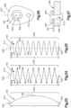
- the section 149 of the conductor 140 that overlies the fabric layer 110 has one or more extendable length portions 500, as shown for example in the schematic view of FIG. 23 .
- the extendable length portion 500 is elongated in a longitudinal direction along an axis 503, and has a proximal end 510 and a distal end 520.
- the distal end 520 is spaced from proximal end 510 at a linear distance D in the longitudinal direction.
- the extendable length portion 500 itself is longer than the linear distance D between the opposite ends 510 and 520. The greater length enables the overlying section 149 of the conductor to 140 elongate in the longitudinal direction when the fabric layer stretches in the longitudinal direction.
- the extendable length portion 500 of the conductor 140 has first segments 530 and second segments 532.
- the first segments 530 reach distally in orientations laterally toward one side of the longitudinal direction.
- the second segments 532 alternate with the first segments 530, and reach distally in orientations laterally toward an opposite side of the longitudinal direction.
- the alternating segments 530, 532 are linear and reach distally in a zig-zag configuration with corners 540 between adjacent segments 530, 532.
- the alternating segments 530, 532 are arcuate and reach distally in a serpentine configuration with turns 550 between adjacent segments 530, 532.
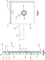
- the electrode connector 166 has a base portion 600 and a column portion 602, both of which have circular cross-sectional shapes centered on an axis 605.
- the base 600 can be adhesively bonded to the interior surface 112 of the fabric layer 110.
- the base 600 can alternatively be adhesively bonded to the exterior surface 114, with the column 602 extending inward through the fabric layer 110. In that condition an electrically nonconductive cap, such as a body of polyurethane gel, would be received over the base 600.
- the column 600 in this example has an internal screw-thread 606 for engaging an external screw thread 608 on the electrode 130. This enables the user to install electrodes 130 at fewer than all of the connectors 166, leaving the remaining connectors 166 free of electrodes 130 at the contact surface 124.
- the conductive human interface 400 is thus adaptable for a user to employ electrodes 130 at only selected locations on the residual limb, although other locations are also available as needed, and thereby to avoid discomfort where unnecessary electrodes 130 might be located.
- FIG. 26 An alternative configuration of the electrode connector 166 is shown in FIG. 26 .
- the base 600 of the connector 160 has an aperture 613 for a fastener to connect the conductor 140 to the base 600.
- the base 600 also has a generally oblong peripheral shape that is elongated on a longitudinal centerline 615.
- the elongated configuration of the base 600 provides space for the aperture 613 without the need to widen the base 600 laterally relative to the size of the circular base 600 in the embodiment of FIG. 22 .
- the electrode connector 166 can thus fit more compactly beside and between adjacent connectors 166 that are aligned in the axial directions 503 shown in FIGS. 23, 24, and 25 .
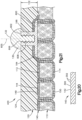
- the fastener can be a rivet 620, which is preferably formed of stainless steel.
- a compliant washer 622 is clamped between the rivet 620 and the conductive path 140 to prevent the conductive path 140 from being damaged by the rivet 620.
- the EMG signals can be communicated to signal processing devices that are located external to the conductive human interface by flexible and durable conductive paths.
- the conductive interfaces can include sensors for providing additional control input.
- temperature sensors, moisture sensors, or both can be used to control temperature control devices provided in the interface (e.g., prosthetic liner).
- the sensors can be configured to detect contact pressures, which can be used as control input to alter the shape or operation of an assistive device.
- signals from the calf area can be used to control an ankle foot orthosis to adjust the stiffness of the device or the position of the components (e.g., ankle location).
- feedback signals can be provided to the user via electrodes to help the user sense and control assistive devices.
- Electrodes are inserted directly into a substantially rigid socket or inner socket.
- EMG electrodes cannot be used to collect information from regions of the user's body that extend substantially outside of the socket. This limits the receptive field for EMG signals to tissues that are substantially inside of the socket.
- Use of a flexible liner with integrated electrodes allows electrodes to be applied to regions of tissue that extend beyond the socket. This allows for EMG signals to be collected from regions of tissue that extend across a joint.
- a flexible liner with embedded electrodes allows for the collection of additional information that can be used to control a prosthetic wrist and hand from, for example, the supinator muscle, the pronator teres muscle, and other muscles, which would not be available with traditional EMG control.
- This additional information can improve the user's control over pronation and supination and other functions.
- This benefit is not limited to pronation and supination, below elbow applications, or upper extremity prosthetics.
- expansion of the EMG receptive field across the elbow can also benefit other functions such as wrist flexion/extension and finger flexion/extension in the upper extremity prosthesis, while placement of electrodes above the knee could collect information from the plantaris muscle to facilitate control of ankle flexion of prostheses for below knee amputees.
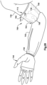
- the conductive human interface 700 of Fig. 28 is associated with a socket 702.
- the socket 702 has a socket opening 703 for insertion of a liner 706.
- the liner 706 has a proximal end portion 710 with a liner opening 713 for insertion of a residual limb 720.
- the liner 706 takes an operative position in which a distal end portion of the liner 706 is received in the socket 702, and the proximal end portion 710 projects outward from the socket opening 703.
- An array of electrodes or sensors 730 are mounted on the proximal end portion 710 of the liner 706 in the same or substantially the same manner as described above regarding the electrodes 130, and are configured to electrically connect with the residual limb 720.
- an electrical connector 738 is included to electrically connect the electrodes or sensors 730 with a prosthetic device 740.
- a corresponding array of conductive paths 750 interconnect the electrodes or sensors with the electrical connector 738.
- the conductive paths 750 can be configured in the same or substantially the same manner as the conductive paths 140 described above.
- One or more of the conductive paths 750 may reach through the socket opening 703 from the proximal end portion 710 of the liner 706 to the distal end portion when the when the liner 706 is in the operative position.
Landscapes
- Health & Medical Sciences (AREA)
- Cardiology (AREA)
- Oral & Maxillofacial Surgery (AREA)
- Transplantation (AREA)
- Engineering & Computer Science (AREA)
- Biomedical Technology (AREA)
- Heart & Thoracic Surgery (AREA)
- Vascular Medicine (AREA)
- Life Sciences & Earth Sciences (AREA)
- Animal Behavior & Ethology (AREA)
- General Health & Medical Sciences (AREA)
- Public Health (AREA)
- Veterinary Medicine (AREA)
- Prostheses (AREA)
Description
- This technology includes conductive human interfaces for transmitting signals between a device and a user of the device, such as electromyographic signals that are transmitted from a user, and transcutaneous electrical nerve stimulation signals that are transmitted to a user.
- Electromyographic (EMG) signals are relatively low powered electrical signals, in the range of about 10 µV to about 1 mV, that are generated in muscle tissue during contraction. Control of assistive devices using EMG signals can increase the functionality and the ease of use for a number of devices. For example, instead of requiring hand or body control of an assistive device such as a prosthetic, the EMG signals can be detected and used as input for the control of the device.
- The low power of EMG signals can be detected by interfaces that place electrodes upon the skin of the user. Generally, additional electrical components are needed to process or amplify the EMG signals in order to generate signals suitable for control input. Thus, the EMG signals must be communicated from the detection site to the electrical components.
-
DE 102014106070 A1 discloses a prosthesis including an elastomeric body and elastomeric conductors. -
US 2007/021841 A1 discloses a prosthesis having a joint that allows for connection and disconnection of a shell to a liner. The joint also allows for rotational movement and effects electrical connection and mechanical connection between the shell and the liner during connection of the shell to the liner and maintains the connection throughout rotation of the shell in relation to the liner. -
US 2014/148916 A1 discloses a liner interface and method of making the liner interface comprising attaching non-compressible deformable electrically conductive receptors to an inner surface of a fabric layer, placing the fabric layer into a female part of a molding machine, axially deforming the deformable receptors from their initial thickness with a male part of the molding machine, injecting a molten gel elastomer into the molding machine to completely surround and adhere to the receptors and inner surface of the tubular fabric layer, allowing the molten gel to cure, and removing the male part from the molding machine and allowing the axially deformed receptors to axially expand beyond the inner surface of the cured liner interface. -
US 2016/194792 A1 discloses a method of making a conductive assembly for use in textiles, the method comprising providing a composite material comprising: a temporary substrate having a first surface and a second surface opposite the first surface; a stitching pattern comprising a plurality of lockstitches on the temporary substrate, such that a conductive thread is disposed at the first surface of the temporary substrate and a thermo-fusible thread is disposed at the second surface; and an insulating layer comprising an adhesive on top of at least part of the conductive thread on the first surface, the adhesive having an activation temperature which is higher than the Vicat softening point, as measured by method A120 of ASTM D1525, of the thermo-fusible thread; and heating the insulating layer and thermo-fusible thread to the activation temperature and curing the adhesive in the insulating layer of the composite material, thereby securing the conductive thread to the insulating layer. -
US 2013/046394 A1 discloses the features of the preamble of claim 1. - The scope of the invention is defined by the appended claims solely. A conductive human interface has a fabric layer with an interior surface and an exterior surface. A soft coating overlies the interior surface of the fabric layer. An electrode is included to connect with a residual limb. A conductive path connects the electrode with an electrical connector which, in turn, connects with a prosthetic device or other assistive device. The conductive path includes a conductor having a section overlying the fabric layer. The overlying section of the conductor can be cord of conductive thread. A support thread can extend through the fabric layer from the exterior surface to the interior surface, and further around the conductor to secure the overlying section of the conductor to the fabric layer.
- The cord of conductive thread can have a monofilament structure, or can alternatively have a multi-filament structure of filaments that are bundled, spun or twisted together. A filament can be formed of nonconductive material that is coated or embedded with electrically conductive elements, or can alternatively be formed of conductive material, such as stainless steel.
- Other embodiments can include alternative conductors such as, for example, conductive fabric and conductive ink.
- The overlying section of the conductor can have an extendable length portion. In given examples, the extendable length portion has a first end, a second end spaced from the first end at a linear distance in a stretchable direction, and a length greater than the linear distance. The greater length enables the conductor to elongate in the stretchable direction when the fabric layer stretches in the stretchable direction. The electrode connector can have a base that is elongated in the stretchable direction.
- In a given example, the conductive human interface is associated with a socket having a socket opening for insertion of a liner. The liner is configured to take an operative position in which a distal end portion of the liner is received in the socket, and a proximal end portion of the liner projects outward from the socket opening. An electrode or sensor is mounted on the proximal end portion of the liner, and is configured to electrically connect with a residual limb. An electrical connector is configured to electrically connect the electrode or sensor with a prosthetic device. A conductive path is configured to connect the electrode or sensor with the electrical connector. The conductive path reaches through the socket opening from the proximal end portion of the liner to the distal end portion when the liner is in the operative position.
- A method of assembling the conductive human interface can include the step of removing the support thread from the fabric layer. In such cases the support thread is preferably dissoluble for removal by dissolving in a solvent such as water.
- Another method of assembly may omit the support thread, and instead secure the conductor to the liner with an adhesive bond. The adhesive bond can be removed, preferably by dissolving in water.
-
-
FIG. 1 depicts a conductive human interface. -
FIG. 2 depicts an exploded view of an interface system including a partial cross-sectional view of the conductive human interface ofFIG. 1 along line 2-2. -
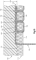
FIG. 3 is an enlargedpartial view 3 of structure shown inFIG. 2 . -
FIGS. 4 and5 depict alternative embodiments of the structure shown inFIG. 3 . -
FIG. 6 is an enlarged partial view of the conductive human interface ofFIG. 2 . -
FIG. 7 is a perspective view an electrical connector. -
FIGS. 8 and 9 depict conductive paths. -
FIGS. 10-11 depict an electrode connector and a conductive path. -
FIG. 12 depicts a closed end of a fabric layer. -
FIG. 13 depicts an alternative embodiment of the structures shown inFIGS. 3-5 . -
FIG. 14 depicts an umbrella of a liner. -
FIG. 15 depicts an alternative embodiment of a conductive human interface. -
FIG. 16 is a sectional view taken on line 16-16 ofFIG. 15 . -
FIG. 17 depicts another alternative embodiment of a conductive human interface. -
FIG. 18 is a sectional view taken on line 18-18 ofFIG. 17 . -
FIG. 19 schematically depicts a processing board. -
FIG. 20 is an enlarged partial view of a conductor shownFIG. 3 . -
FIG. 21 depicts another alternative embodiment of the structures shown inFIGS. 3-5 and13 . -
FIG. 22 depicts the structure ofFIG. 21 in different condition. -
FIGS. 23-25 depict alternative embodiments of a conductor. -
FIG. 26 depicts an alternative embodiment of an electrode connector. -
FIG. 27 depicts the connector ofFIG. 26 in connection with other parts. -
FIG. 28 depicts an alternative embodiment of a conductive human interface. - The structures illustrated in the drawings include examples of the elements recited in the claims. The illustrated structures thus include examples of how a person of ordinary skill in the art can make and use the claimed invention. These examples are described to meet the enablement and best mode requirements of the patent statute without imposing limitations that are not recited in the claims. One or more elements of an embodiment may be used in combination with, or as a substitute for, one or more elements of another embodiment as needed for any particular implementation of the invention.
- Referring now to
FIGS. 1 and2 , an embodiment of a conductivehuman interface 100 is schematically depicted. This example of a conductivehuman interface 100 is configured to capture electrical signals from the skin of a user and act as a physical interface with the user. In some embodiments, the conductivehuman interface 100 can also be configured to interface with an assistive device. The assistive device can be any device supplemental to the body of a user that cooperates with the neuromuscular and skeletal system of the user such as, for example, a prosthetic device (e.g., a prosthetic socket), an orthotic device, an exoskeletal device, a powered wheelchair, or the like. Accordingly, while certain embodiments of the present disclosure relate to aprosthetic liner 102 as shown inFIG. 1 , the conductivehuman interface 100 can include theprosthetic liner 102, a sleeve, a band, a pad, or the like. - The conductive
human interface 100 in the illustrated example includes afabric layer 110 configured to form a flexible substrate. Thefabric layer 110 can include one or more fabric materials such as, for example, stretch controlling fabrics, stretchable non-woven materials, fiber-on-end fabrics, or the like. Stretch-controlling fabric can be more stretchable in one direction than another direction. For example, a stretch-controlling fabric can have a limited stretch direction that is substantially orthogonal to a non-limited stretch direction. Accordingly, when the conductivehuman interface 100 includes aprosthetic liner 102, the stretch-controlling fabric can be oriented to permit greater stretch in a circumferential direction than in a longitudinal direction (i.e., along the length of theprosthetic liner 102 in the direction of the longitudinal axis 103). - Referring now to
FIG. 3 , thefabric layer 110 can include aninterior surface 112 and anexterior surface 114. Theinterior surface 112 can form a boundary with asoft coating 120 configured for comfortable long term wear. Thesoft coating 120 can be formed from materials having a hardness on the Shore 00 scale such as, for example, a hardness of less than about 75 on the Shore 00 scale in one embodiment, or a hardness of between about 15-35 on the Shore 00 scale in another embodiment. Accordingly, thesoft coating 120 can be formed from a soft polymer such as, for example, thermoplastic elastomers (TPE), silicones, block copolymers, urethanes, or the like. Thethickness 122 of thesoft coating 120, as measured from theinterior surface 112 of thefabric layer 110 to thecontact surface 124 of thesoft coating 120, can be less than about 1 inch (2.5 cm) such as, for example, less than about 0.75 inches (1.91 cm) in one embodiment, or between about 0.150 (0.381 cm) and about 0.50 inches (1.27 cm). - Referring to
FIGS. 2 and3 , the conductivehuman interface 100 includes one ormore electrodes 130 configured to make contact with the skin of the user and to receive EMG signals produced by muscles of the user. Generally, theelectrodes 130 can be formed from conductive material such as, for example, metal or a polymeric material impregnated with conductive particles such as, for example, silicone impregnated with carbon particles. Theelectrodes 130 can be substantially even with thecontact surface 124 of thesoft coating 120 or protrude beyond thecontact surface 124 of thesoft coating 120. Eachelectrode 130 includes adetection surface 132 shaped to promote electrical contact with the skin of the user. For example, thedetection surface 132 can be domed shaped, as shown for example inFIG. 3 , or substantially flat, corrugated or any other shape or surface treatment that promotes electrical conductivity with the skin. - Referring to
FIGS. 2-5 , the conductivehuman interface 100 further includes aconductive path 140 for electrically connecting eachelectrode 130 to another component. As used herein, the phrase "electrically connect" means to provide a medium for the transmission of electrical signals from one object to another object. Theconductive path 140 generally includes a flexible conductor such as, for example, conductive thread 142 (FIG. 3 ), conductive fabric 144 (FIG. 4 ), a conductive ink 145 (FIG. 5 ), or combinations thereof. Asection 149 of eachconductor interior surface 112 of the fabric layer. - The conductive thread 142 (
FIG. 3 ) is configured as a cord with either a monofilament structure or a multi-filament structure. A conductive filament can be formed of a conductive material, such as stainless steel, and alternatively could be formed of a non-conductive substrate material that is coated or embedded with electrically conductive elements such as, for example, silver, carbon, nickel, copper, gold, titanium, or the like. Substrates can include cotton, polyester, nylon, aramids, or the like. A multi-filament structure can be formed from a plurality of conductive filaments that are bundled, spun or twisted together into a substantially cord-like shape. In some embodiments, theconductive thread 142 can be formed from multiple plys of thread that are spun or twisted together into a substantially cord-like shape such as, for example, 2 plys in one embodiment, or 4 plys in another embodiment. Theconductive thread 142 can be characterized by linear resistance. In some embodiments, theconductive thread 142 can have a linear resistance of less than about 10 Ω/in (0,254 Ω/m) such as, for example, less than about 6 Ω/in (0,152 Ω/m) in one embodiment, between about 0.5 Ω/in (0,0127 Ω/m) to about 3.5 Ω/in (0,0889 Ω/m) in another embodiment. Theconductive thread 142 can also be characterized by linear density. In some embodiments, theconductive thread 142 can have a linear density of at least about 2,000 yd/lb (4032 m/kg) such as, for example, between about 3,000 yd/lb (6048 m/kg) and about 9,500 yd/lb i (19151 m/kg) in one embodiment, between about 3,500 yd/lb a (7056 m/kg) and about 4,000 yd/lb (8064 m/kg) in another embodiment, or between about 8,500 yd/lb (17135 m/kg) and about 9,000 yd/lb (18143 m/kg) in another embodiment. - In distinction from the cord of the
conductive thread 142, the conductive fabric 144 (FIG. 4 ) can be a substantially sheet like material formed from a plurality of conductive filaments orconductive threads 142 that are woven, knitted, or bonded together via chemical, mechanical, heat or solvent treatments. The conductive ink 145 (FIG. 5 ) can be a conductive body formed from a conductive liquid that has been dried, cured, cooled or a combination thereof. Theconductive ink 145 can include electrically conductive elements, as described above, suspended within a substrate (e.g., polymer film). - Referring again to
FIG. 2 , the conductivehuman interface 100 can include one ormore sensors 146 configured to detect physical characteristics of the conductivehuman interface 100, the skin of the user, or both. The one ormore sensors 146 can be electrically connected to theconductive path 140 in a manner similar to the electrical connection of theelectrodes 130, as described in greater detail below. It is noted that the term "sensor," as used herein, can mean a device that measures a physical quantity and converts it into an electrical signal, which is correlated to the measured value of the physical quantity. Asensor 146 can thus comprise a temperature sensor, a moisture sensor, a gyroscope, shear sensor, pressure sensor, force sensor (e.g., normal force, sliding force), distance sensor, or combinations thereof. At least a portion of the one or more sensors can be embedded within thesoft coating 120. Alternatively or additionally, thesensor 146 can include a power source, processor, or both located external to the conductivehuman interface 100. For example, the components of thesensor 146 can be electrically connected via theconductive path 140. - Referring to
FIGS. 2 and7 , the conductivehuman interface 100 can include anelectrical connector 148 configured to electrically connect eachconductive path 140 with another component. Theelectrical connector 148 can include conductive members 134 (FIG. 7 ), each of which is configured to be electrically connected to one of theconductive paths 140. Specifically, aconductive member 134 can include features configured to provide a mechanical connection with fabric or thread. For example, theconductive member 134 can include a feature that promotes a knotted connection such as, but not limited to, a slot (e.g., "L" shaped slot), a boat cleat shaped member, a knob, a hook, orifices, or the like. Accordingly, an electrical connection can be formed by wrapping a portion (e.g., a connector lead 172) of theconductive path 140 around theconductive member 134, tying the portion of theconductive path 140 to theconductive member 134 or combinations thereof. In some embodiments, theelectrical connector 134 can be configured to transition from relatively flexible conductors to more rigid conductors. For example, theelectrical connector 148 can include a separable electrical connector 136 (e.g., pins, sockets, etc.) electrically connected to theconductive members 134. - Referring to
FIGS. 2 and3 , a method for forming the conductivehuman interface 100 can include providing thefabric layer 110 in the desired shape such as, for example, as a panel, a tube, or a sock. In embodiments where thefabric layer 110 is shaped into a sock (FIG. 2 ), the conductivehuman interface 100 can be provided as aprosthetic liner 102 configured to serve as an interface between a residual limb and a prosthetic socket. Accordingly, theprosthetic liner 102 can extend between anopen end 104 and aclosed end 106. - The
conductive path 140 can be attached to thefabric layer 110. In embodiments where theconductive path 140 includesconductive thread 142, theconductive thread 142 can be stitched to thefabric layer 110 using a support thread 150 (FIG. 3 ), which can be non-conductive. For example, one of theconductive thread 142 and thesupport thread 150 can be provided in the thread feed of a sewing machine, and the other can be provided in the bobbin. Accordingly, a majority of theconductive thread 142 can be located on theinterior surface 112 of thefabric layer 110. Additionally, a majority of thesupport thread 150 can be located on theexterior surface 114 of thefabric layer 110. - The tension applied at each of the
needle punctures 152 through thefabric layer 110 can be controlled to improve the flexibility of theconductive path 140. For example, flexibility of theconductive path 140 can be improved by having thesupport thread 150 loop around theconductive thread 142 inwards above theinterior surface 112 of thefabric layer 110 as shown, for example, inFIG. 3 . That is, thesupport thread 150 can be pushed completely through thefabric layer 110 and separated from theinterior surface 112 of thefabric layer 110 by theconductive thread 142 at theneedle puncture 152. Accordingly, theconductive thread 142 can be held to theinterior surface 112 of thefabric layer 110 by thesupport thread 150, which can be provided both on theinterior surface 112 and theexterior surface 114 of the fabric. - Referring to
FIGS. 8 and 9 , in embodiments where theconductive path 140 includesconductive thread 142, the durability of theconductive path 140 can be improved by controlling the aspect ratio along theconductive path 140. The aspect ratio can be determined by dividing awidth 154 betweenadjacent needle punctures 152 by alength 156 between theadjacent needle punctures 152. Preferably, the aspect ratio can be greater than about 1 such as, for example, greater than about 1.1 in one embodiment, greater than about 1.25 in another embodiment, or about 1.5 in a further embodiment. Generally, thelength 156 refers to a direction substantially parallel to the overall direction in which theconductive path 140 is elongated between its opposite ends, and thewidth 154 refers to a direction substantially orthogonal to the length. Further improvements can be provided by aligning thelength 156 betweenpunctures 152 along the length of theprosthetic liner 102. In embodiments where theconductive thread 142 is stitched with a machine, the direction thefabric layer 110 is fed through the machine can define the direction of theconductive path 140. - The
conductive thread 142 can include a span 158 (FIG. 8 ) formed between anelectrode patch 160 and aconnector patch 162. Theelectrode patch 160 and theconnector patch 162 can be configured to anchor theconductive path 140. In some embodiments, the aspect ratio of theconductive thread 142 at theelectrode patch 160 and theconnector patch 162 can be greater than the aspect ratio of theconductive thread 142 of thespan 158. For example, the aspect ratio of theconductive thread 142 at theelectrode patch 160 and theconnector patch 162 can be at least twice as large as the aspect ratio of theconductive thread 142 of thespan 158 such as, for example, at least about four times as large. - Additionally, manufacturability of the conductive
human interface 100 can be improved by overlapping multiple layers of theconductive thread 142 at theelectrode patch 160, theconnector patch 162, or both. For example, the layers can be overlapped to form apatch conductive thread 142 is stitched with a machine, the feed direction can be reversed back and forth over the location of theelectrode patch 160, theconnector patch 162, or both to provide the number of layers desired to form thepatch conductive thread 142 to self-knot or self-entangle, which can improve the overall durability of theconductive path 140 and reduce manufacturing time. Accordingly, theelectrode patch 160, theconnector patch 162, or both can include more layers than thespan 158. In some embodiments, theelectrode patch 160 can include a greater number of layers of theconductive thread 142 than theconnector patch 162. - Referring to
FIGS. 4 and6 , in embodiments where theconductive path 140 includesconductive fabric 144, theconductive fabric 144 can be attached to theinterior surface 112 of thefabric layer 110 such as, for example, with adhesive, stitching, or the like. In some embodiments, theconductive fabric 144 can be cut to a shape that is configured to extend between anelectrode 130 and theelectrical connector 148. The shape of theconductive fabric 144 can include anelectrode portion 164 configured to be attached to theelectrode 130. Accordingly, theelectrode portion 164 can be correspondingly shaped to theelectrode 130. In embodiments where theconductive path 140 includesconductive ink 145, theconductive ink 145 can be applied directly to theinterior surface 112 of thefabric layer 110. - Referring to
FIGS. 3-6 and9-10 , a method for forming the conductivehuman interface 100 can include electrically connecting anelectrode connector 166 to theconductive path 140. Theelectrode connector 166 can be formed from conductive materials such as, for example, a metal (e.g., copper, aluminum, gold, silver, etc.), a graphite material, or a conductive polymer. In embodiments where theconductive path 140 includesconductive thread 142, theelectrode patch 160 can be configured to electrically connect with theelectrode connector 166. For example, theconductive thread 142 of theelectrode patch 160 can define a conductive region at theinterior surface 112 of thefabric layer 110 for promoting electrical contact with theelectrode connector 166. - Additionally, the
electrode connector 166 can be configured to mechanically connect to theconductive path 140 and theelectrode 130. Theelectrode connector 166 can include one or more features that promote a knotted connection, as described above, with an electrode lead 168 (FIGS. 8 and 9 ) extending from theelectrode patch 160. Accordingly, theelectrode lead 168 can be wrapped or tied to the features of theelectrode connector 166, which can improve the contact between theelectrode connector 166 and theelectrode patch 160. - Alternatively or additionally, a
fabric patch 170 can be used to provide a mechanical connection between theelectrode connector 166 and theelectrode patch 160, as best shown inFIG. 10 . In some embodiments, thefabric patch 170 can cover theelectrode connector 166 and can be adhered to theinterior surface 112 of thefabric layer 110. Accordingly, theelectrode connector 166 can be positioned between thefabric patch 170 and theinterior surface 112 of thefabric layer 110 as shown inFIG. 3 . Moreover, thefabric patch 170 can be configured to isolate the electrical connection between theelectrode patch 160 and theelectrode connector 166 from thesoft coating 120. For example, when thefabric patch 170 is applied before thesoft coating 120, undesired intrusion of thesoft coating 120 between theelectrode connector 166 and theelectrode patch 160 can be mitigated. Accordingly, the mechanical and electrical connection can be improved. - Referring to
FIGS. 4 and6 , in embodiments where theconductive path 140 includesconductive fabric 144, theelectrode connector 166 can be electrically and mechanically connected with theelectrode portion 164 of theconductive fabric 144. For example, theelectrode portion 164 can partially cover theelectrode connector 166 and extend beyond theelectrode connector 166. The overhangingportion 171 of theelectrode portion 164 can be adhered to theinterior surface 112 of thefabric layer 110. Thus, theelectrode connector 166 can be positioned between theelectrode portion 164 of theconductive fabric 144 and theinterior surface 112 of thefabric layer 110. - Referring to
FIGS. 2 and5 , in embodiments where theconductive path 140 includesconductive ink 145, theelectrode connector 166 can be electrically and mechanically connected with theelectrode portion 165 of theconductive ink 145. For example, theelectrode portion 165 can be applied directly to theinterior surface 112 of thefabric layer 110 such that theelectrode portion 165 is at least as large as theelectrode connector 166. Theconductive ink 145 can be cured prior to connecting with theelectrode connector 166. Alternatively, theelectrode connector 166 can be connected to theelectrode portion 165, while theconductive ink 145 is in an uncured state. Accordingly, the curing process can contribute to the quality of the connection therebetween. Alternatively or additionally, thefabric patch 170 can be used to isolate and improve the mechanical connection and the electrical connection between theelectrode connector 166 and theelectrode portion 165, as noted above. Specifically, theelectrode connector 166 can be positioned between thefabric patch 170 and theelectrode portion 165 of theconductive ink 145. Additionally, thefabric patch 170 can substantially cover theelectrode portion 165, such that thefabric patch 170 is adhered to theinterior surface 112 of thefabric layer 110 around theelectrode portion 165. - Referring to
FIGS. 11 and12 , a method for forming the conductivehuman interface 100 can include arranging connector leads 172 with respect to thefabric layer 110. In some embodiments, theconductive path 140 can include connector leads 172 that extend beyond theexterior surface 114 of thefabric layer 110. The connector leads 172 can be formed from theconductive thread 142, theconductive fabric 144,conductive ink 145 applied to a non-conductive fabric, or combinations thereof. Aconnector lead 172 can extend from theconnector patch 162 and through one or more orifices in thefabric layer 110 as shown, for example, inFIG. 13 . For example, in embodiments where the conductivehuman interface 100 includes theprosthetic liner 102, the connector leads 172 can extend through thefabric layer 110 at theclosed end 106. - In embodiments where the
conductive path 140 includesconductive ink 145, theconductive ink 145 can be electrically connected to theconnector lead 172 at theconnector patch 162. For example, theconductive ink 145 can be applied to theinterior surface 112 of thefabric layer 110. After theconductive ink 145 is applied, theconnector patch 162 can be stitched upon theconductive ink 145 with theconductive thread 142. Accordingly, each of theneedle punctures 152 can be formed through theconductive ink 145 and theconnector lead 172 can be formed withconductive thread 142. In embodiments where theconnector lead 172 is formed of theconductive fabric 144 or theconductive ink 145 applied to a non-conductive fabric, theconnector lead 172 can be applied over theconductive ink 145 and the fabric of theconnector lead 172 can be adhered to theinterior surface 112 of thefabric layer 110. Accordingly, theconductive ink 145 can be positioned between theconnector lead 172 and theinterior surface 112 of thefabric layer 100. - In alternative embodiments, the
conductive ink 145 can be applied over theconnector lead 172, i.e., theconnector lead 172 can be positioned between theconductive ink 145 and theinterior surface 112 of thefabric layer 100. For example, theconnector lead 172 can be formed fromconductive thread 142 and theconductive ink 145 can be applied over theconnector patch 162. In embodiments where theconnector lead 172 is formed of theconductive fabric 144 or theconductive ink 145 applied to a non-conductive fabric, theconductive ink 145 can be applied over theconnector lead 172. - In a method for forming the conductive
human interface 100, thesoft coating 120 can be applied in a gel state and cured within a mold to form thesoft coating 120. In some embodiments, thesoft coating 120 can be applied after theconductive path 140 is formed upon thefabric layer 110. Accordingly, theconductive path 140 can be covered by or embedded within thesoft coating 120. In embodiments, where the connector leads 172 extend through thefabric layer 110, the orifices in thefabric layer 110 can be sized such that the connector leads 172 are compressed by thefabric layer 110. For example, each orifice can be smaller than the connector leads 172 that pass through the orifice. Thus, the orifices can be configured to mitigate permeation of thesoft coating 120. - The
electrode connector 166 can include one or more features that promote a mechanical connection with theelectrode 130 such as, for example, a threaded connection, a friction fit, a clamping feature, a pin connector, a socket connector, or the like. Thus, while the electrode connector is depicted inFIG. 6 as a metal tee nut, the embodiments provided herein are not so limited. Accordingly, theelectrode 130 can be connected to theelectrode connector 166 after thesoft coating 120 is applied to thefabric layer 110. - The
electrode connector 166 can be configured to protrude away from theinterior surface 112 of thefabric layer 110. For example, the feature for connecting with theelectrode 130 can be offset from theinterior surface 112 of thefabric layer 110. In embodiments with thefabric patch 170, the feature for connecting with theelectrode 130 can protrude through thefabric patch 170. Accordingly, theelectrode connector 166 can at least partially extend through thesoft coating 120 and can mate with theelectrode 130 after thesoft coating 120 is applied to thefabric layer 110. - In embodiments where the
electrodes 130 are formed from polymeric materials, theelectrodes 130 can be applied directly to the conductive path 140 (e.g., theelectrode patch 160, theelectrode portion 164, or the electrode portion 165). Accordingly, theelectrodes 130 can make surface contact with theconductive path 140 or both theconductive path 140 and theinterior surface 112 of thefabric layer 110. In some embodiments, the polymeric material can be applied directly to theconductive path 140 in a gel state and cured to form theelectrode 130. The direct contact allows for theelectrode connector 166 to be omitted in certain embodiments. In some embodiments, the polymeric material of theelectrodes 130 can be applied before thesoft coating 120 is applied. Alternatively, the polymeric material of theelectrodes 130 can be applied after thesoft coating 120 is applied. For example, a removable body can cover the electrode sites on theconductive path 140, while thesoft coating 120 is applied. The removable body can then be removed to allow the polymeric material of theelectrodes 130 to be applied to the electrode sites. - Referring to
FIG. 2 and7 , a method for forming the conductivehuman interface 100 can include electrically connecting theconductive path 140 to theelectrical connector 148. Specifically, each of the connector leads 172 can be electrically and mechanically connected to one of theconductive members 134 as shown, for example, inFIG. 7 . Accordingly, the signals can be communicated by each of theconductive paths 140 to an assistive device in communication with the separableelectrical connector 136. - Referring again to
FIGS. 1 and2 , theprosthetic liner 102 can include anumbrella 174 formed at theclosed end 106 and external to theexterior surface 114 of thefabric layer 110. In some embodiments, theumbrella 174 can be formed around theelectrical connector 148. For example, theumbrella 174 can be molded to theexterior surface 114 of thefabric layer 110 out of relatively hard materials such as, for example, a hard urethane. Accordingly, the connector leads 172 can extend through thefabric layer 110 at theclosed end 106 of theprosthetic liner 102 above theumbrella 174. - The
umbrella 174 can be configured to electrically connect with a proximal interface 176 (FIG. 2 ). Specifically, theumbrella 174 can be correspondingly shaped to theproximal interface 176. Theproximal interface 176 can include aprocessing board 178 configured to electrically connect with the separable electrical connector 136 (FIG. 7 ) of theelectrical connector 148. For example, theprocessing board 178 can include a separableelectrical connector 179 configured to connect with the separableelectrical connector 136 of theelectrical connector 148. In some embodiments, the separableelectrical connector 136 of theelectrical connector 148 can be at least partially revealed at a face 180 (FIG. 14 ) of theumbrella 174. - The
umbrella 174 can be configured to mechanically connect with theproximal interface 176. For example, a fastener 182 (e.g., threaded coupling) can be provided on theface 180 of theumbrella 174. It is noted that, theprosthetic liner 102 may deteriorate more rapidly than the components (e.g., signal processors, microprocessors, memory, battery, etc.) of theprocessing board 178 of theproximal interface 176. Accordingly, theproximal interface 176 can be reused when theprosthetic liner 102 needs to be replaced. - The
proximal interface 176 in the illustrated example is configured to be coupled and decoupled with a distal interface 184 (FIG. 2 ) on a daily basis. Thedistal interface 184 can be attached to a prosthetic socket. Each of thedistal interface 184 and theproximal interface 176 can include magnetic members that are configured to form a magnetic coupling therebetween. Additionally, thedistal interface 184 and theproximal interface 176 can be configured to be decoupled by relative rotation which displaces the magnetic members from one another. An additional clamping member can be provided to selectively retain thedistal interface 184 and theproximal interface 176 in alignment to promote the magnetic coupling. - Referring
FIGS. 15 and16 , an embodiment of a conductivehuman interface 200 can be substantially tubular. For example, the conductivehuman interface 200 can extend between a firstopen end 204 and a secondopen end 206. Accordingly, the conductivehuman interface 200 can be provided as, for example, an arm sleeve, a leg sleeve, a wrist band, a head band, or the like. Generally, the conductivehuman interface 200 can include thefabric layer 110, thesoft coating 120, theelectrode 130, thesensor 146, and theelectrical connector 148, as described herein with respect to the conductivehuman interface 100. Additionally, the conductivehuman interface 200 can be formed in substantially the same way as the conductivehuman interface 100. In some embodiments, theelectrical connector 148 can be provided on theexterior surface 114 of thefabric layer 110 between the firstopen end 204 and the secondopen end 206. Alternatively, theelectrical connector 148 can be provided at the firstopen end 204, the secondopen end 206, or both. - Referring to
FIGS. 17 and18 , an embodiment of a conductivehuman interface 300 can be formed as a substantially sheet shaped body. For example, the conductivehuman interface 300 can have a thickness that is defined by thefabric layer 110 and thesoft coating 120 and demarcated by aperimeter 302. It is noted that, while theperimeter 302 is depicted inFIG. 17 as being substantially rectangular, the perimeter can be contoured to match with any desired body part. Optionally, the conductivehuman interface 300 can include aband 304 configured to wrap around a user and secure the conductivehuman interface 300 to the desired body part. Generally, the conductivehuman interface 300 can include thefabric layer 110, thesoft coating 120, theelectrode 130, thesensor 146, and theelectrical connector 148, as described herein with respect to the conductivehuman interface 100. In some embodiments, theelectrical connector 148 can be provided on theexterior surface 114 of thefabric layer 110. Additionally, the conductivehuman interface 300 can be formed in substantially the same way as the conductivehuman interface 100. - Referring to
FIGS. 2 and19 , theprocessing board 178 can be operable to communicate electrical signals with theelectrode 130, thesensor 146, or both. Theprocessing board 178 can include one ormore processors 190 for executing machine readable instructions to perform signal communication functions, as described herein. The term "processor" can mean any device capable of executing machine readable instructions. Accordingly, each processor can be a controller, an integrated circuit, a microchip, a signal processor, or any other device capable of implementing logic. Theprocessing board 178 can includememory 192 communicatively coupled to the one or more processors 190 (generally depicted as double arrowed lines). As used herein, the phrase "communicatively coupled" can mean that components are capable of exchanging data signals with one another such as, for example, electrical signals via conductive medium, electromagnetic signals via air, optical signals via optical waveguides, and the like. Thememory 192 described herein may be RAM, ROM, a flash memory, a hard drive, or any device capable of storing machine readable instructions. - Additionally, it is noted that the functions described herein can be provided as machine readable instructions stored on the
memory 192 and executed by the one ormore processors 190. The machine readable instructions can be provided in any programming language of any generation (e.g., 1GL, 2GL, 3GL, 4GL, or 5GL) such as, e.g., machine language that may be directly executed by the processor, or assembly language, object-oriented programming (OOP), scripting languages, microcode, etc., that may be compiled or assembled into machine readable instructions and stored on a machine readable medium. Alternatively, the functions, modules, and processes described herein may be written in a hardware description language (HDL), such as logic implemented via either a field-programmable gate array (FPGA) configuration or an application-specific integrated circuit (ASIC), and their equivalents. Accordingly, the functions described herein may be implemented in any conventional computer programming language, as pre-programmed hardware elements, or as a combination of hardware and software components. - The
processing board 178 can be configured to transform EMG signals detected by theelectrode 130 into control signals for an assistive device. Alternatively or additionally, theprocessing board 178 can be configured to transform sensor signals communicated by thesensor 146 into control signals for an assistive device. For example, the separableelectrical connector 179 can be communicatively coupled with the one ormore processors 190. Additionally, theprocessing board 178 can includedevice communication hardware 194 communicatively coupled to the one ormore processors 190. Thedevice communication hardware 194 can be configured to communicate, i.e., send and/or receive data signals via any wired or wireless communication protocol such as, for example, LIN bus, CAN bus, USB, FIREWIRE, IrDA, BLUETOOTH, Wireless USB, Z-WAVE, ZIGBEE, or the like. Accordingly, the one ormore processors 190 can receive signals via the separableelectrical connector 179 and transform the signals into control signals. The control signals can then be transmitted via thedevice communication hardware 194 to the assistive device. - Additionally, the
processing board 178 can be configured to transmit electrical signals to theelectrode 130. For example, the electrical signals can be configured to stimulate nerve endings, create information flowing into the body, or both. In some embodiments, theprocessing board 178 can include asignal generator 196 configured to generate electrical signals that can be communicated to theelectrode 130. For example, thesignal generator 196 can be communicatively coupled to the separableelectrical connector 179 and the one ormore processors 190. Accordingly, the one ormore processors 190 can cause thesignal generator 196 to generate the desired electrical signal. The electrical signal can be transmitted to theelectrode 130 via theconductive path 140 and the separableelectrical connector 136. Alternatively, the electrical signals can be provided directly to the separableelectrical connector 179 via thedevice communication hardware 194. Accordingly, in some embodiments, thesignal generator 196 is omitted. - The electrical signals can configured for Transcutaneous electrical nerve stimulation (TENS). Thus, the
electrode 130 can be aligned with the desired nerve ending to manage pain. For example, amputees can experience phantom limb pain, i.e., pain that is sensed as coming from an amputated limb. For example, nerve endings at the site of amputation can stimulate the brain in a manner that is interpreted as pain from the removed limb. Alternatively or additionally, the electrical signals can be transmitted to muscle or nerve endings as feedback from an assistive device. For example, amputees using assistive devices such as, for example, a prosthetic foot may have difficulty detecting uneven surfaces. Often times, the amputee may need to look directly at the assistive device in order to traverse an uneven surface. In some embodiments, the assistive device can be provided with sensors configured to detect the uneven surface such as, for example, load sensors to detect the amount and type of loading, and contact sensors configured to detect contact with the surface. In some embodiments, the sensor information can be communicated to theelectrode 130 as feedback that can stimulate the brain. For example, the one ormore processors 190 can receive sensor data and cause thesignal generator 196 to generate the desired electrical signal. The one ormore processors 190 can encoded the electrical signal according to the sensor data. Alternatively, the electrical signals can be provided directly to the separableelectrical connector 179 via thedevice communication hardware 194. - As described above with reference to the embodiment of
FIG. 3 , theconductor 140 can be a cord ofconductive thread 142 formed of conductive filaments that are spun or twisted together. An example of such acord 300 is shown in greater detail inFIG. 20 . Thefilaments 302 can include non-conductive substrate material that is coated or embedded with electrically conductive elements. Thefilaments 302 can alternatively be formed of conductive material such as, for example, stainless steel. In each case, thefilaments 302 preferably have a Z twist for sewing, as shown inFIG. 20 . - Another embodiment of a conductive
human interface 400 is shown inFIGS. 21 and22 . Specifically, the conductivehuman interface 400 has a partially assembled condition as shown inFIG. 21 , and has a more fully assembled condition as shown inFIG. 22 . - In this embodiment, the conductive
human interface 400 has many parts that correspond with parts of the conductivehuman interface 100 described above with reference toFIGS. 2 and3 . This is indicated by the use of the same reference numbers for such corresponding parts. The conductivehuman interface 400 thus includes afabric layer 110 having aninterior surface 112 and anexterior surface 114, with asoft coating 120 overlying theinterior surface 112. Anelectrode 130 is configured to electrically connect with a residual limb. Aconductive path 140 is configured to connect theelectrode 130 with an electrical connector 148 (FIG. 2 ) which, in turn, is configured to electrically connect with a prosthetic device. Theconductive path 140 includes aconductor 142 having asection 149 overlying theinterior surface 112 of thefabric layer 110 between thesoft coating 120 and thefabric layer 110. - In the partially assembled condition of
FIG. 21 , the conductivehuman interface 400 includesnonconductive support thread 150 extending through thefabric layer 110 from theexterior surface 114 to theinterior surface 112. Thesupport thread 150 extends further around theconductor 142 to secure theoverlying section 149 of theconductor 142 to thefabric layer 110. - The conductive
human interface 400 is advanced from the partially assembled condition ofFIG. 21 to the more fully assembled condition ofFIG. 22 by removing thesupport thread 150. Thesupport thread 150 is preferably dissoluble for removal by dissolving in a solvent such as water. Theneedle punctures 152 and the inherent porosity of thefabric layer 110 may enable the solvent to penetrate from theexterior surface 114 of thefabric layer 110 sufficiently to dissolve thesupport thread 150 completely. Removing thesupport thread 150 provides theexterior surface 114 with a smoother contour and texture. At theinterior surface 112, theoverlying section 149 of theconductor 142 remains secured in theconductive path 140, but is released from thesupport thread 150 to enable a slight amount of shifting on thesurface 112 as needed in response to forces imparted from the residual limb or the connected prosthetic device. - In an alternative method of assembly the
support thread 150 can be omitted. Such a method could comprise the steps of connecting a conductor between an electrical connector and an electrode or sensor; placing a section of the conductor in a position overlying an interior surface of a fabric layer; forming an adhesive bond securing the overlying section of the conductor to the interior surface of the fabric layer; applying a soft coating over the interior surface of the fabric layer, the overlying section of the conductor, and portions of the support thread reaching around the conductor; and removing the adhesive bond. - In the foregoing method, the adhesive bond can be formed of a dissoluble adhesive material, and preferably a water-dissoluble adhesive material. The step of removing the adhesive bond would then comprise dissolving the adhesive bond, and more specifically dissolving the adhesive bond in water. A cornstarch mixture could serve as the water-dissoluble adhesive material.
- In each embodiment, the
conductors 140 are preferably elongated lengthwise of the respective fabric layer. This is illustrated by the examples shown inFIGS. 8, 9 , and12 , where theconductors 140 are shown to be elongated in directions either parallel or generally oriented in alignment with the length of theprosthetic liner 102 along theaxis 103. In each case, thesection 149 of theconductor 140 that overlies thefabric layer 110 has one or moreextendable length portions 500, as shown for example in the schematic view ofFIG. 23 . Theextendable length portion 500 is elongated in a longitudinal direction along anaxis 503, and has aproximal end 510 and adistal end 520. Thedistal end 520 is spaced fromproximal end 510 at a linear distance D in the longitudinal direction. However, theextendable length portion 500 itself is longer than the linear distance D between the opposite ends 510 and 520. The greater length enables theoverlying section 149 of the conductor to 140 elongate in the longitudinal direction when the fabric layer stretches in the longitudinal direction. - In the example shown schematically in
FIG. 24 , theextendable length portion 500 of theconductor 140 hasfirst segments 530 andsecond segments 532. Thefirst segments 530 reach distally in orientations laterally toward one side of the longitudinal direction. Thesecond segments 532 alternate with thefirst segments 530, and reach distally in orientations laterally toward an opposite side of the longitudinal direction. As shown in 23, the alternatingsegments corners 540 betweenadjacent segments FIG. 24 , the alternatingsegments turns 550 betweenadjacent segments - Referring again to
FIGS. 21 and22 , theelectrode connector 166 has abase portion 600 and acolumn portion 602, both of which have circular cross-sectional shapes centered on anaxis 605. The base 600 can be adhesively bonded to theinterior surface 112 of thefabric layer 110. The base 600 can alternatively be adhesively bonded to theexterior surface 114, with thecolumn 602 extending inward through thefabric layer 110. In that condition an electrically nonconductive cap, such as a body of polyurethane gel, would be received over thebase 600. - The
column 600 in this example has an internal screw-thread 606 for engaging anexternal screw thread 608 on theelectrode 130. This enables the user to installelectrodes 130 at fewer than all of theconnectors 166, leaving the remainingconnectors 166 free ofelectrodes 130 at thecontact surface 124. The conductivehuman interface 400 is thus adaptable for a user to employelectrodes 130 at only selected locations on the residual limb, although other locations are also available as needed, and thereby to avoid discomfort whereunnecessary electrodes 130 might be located. - An alternative configuration of the
electrode connector 166 is shown inFIG. 26 . In this configuration, thebase 600 of theconnector 160 has anaperture 613 for a fastener to connect theconductor 140 to thebase 600. The base 600 also has a generally oblong peripheral shape that is elongated on alongitudinal centerline 615. The elongated configuration of thebase 600 provides space for theaperture 613 without the need to widen the base 600 laterally relative to the size of thecircular base 600 in the embodiment ofFIG. 22 . Theelectrode connector 166 can thus fit more compactly beside and betweenadjacent connectors 166 that are aligned in theaxial directions 503 shown inFIGS. 23, 24, and 25 . - As shown in
FIG. 27 , the fastener can be arivet 620, which is preferably formed of stainless steel. Acompliant washer 622 is clamped between therivet 620 and theconductive path 140 to prevent theconductive path 140 from being damaged by therivet 620. - It should now be understood that the embodiments described herein can provide relatively durable and comfortable conductive human interfaces. The EMG signals can be communicated to signal processing devices that are located external to the conductive human interface by flexible and durable conductive paths. Moreover, the conductive interfaces can include sensors for providing additional control input. For example, temperature sensors, moisture sensors, or both can be used to control temperature control devices provided in the interface (e.g., prosthetic liner). Alternatively or additionally, the sensors can be configured to detect contact pressures, which can be used as control input to alter the shape or operation of an assistive device. Specifically, signals from the calf area can be used to control an ankle foot orthosis to adjust the stiffness of the device or the position of the components (e.g., ankle location). Moreover, feedback signals can be provided to the user via electrodes to help the user sense and control assistive devices.
- There are other benefits that arise from inserting electrodes into a flexible liner, including increasing the number of muscle sites that can be accessed for collecting EMG signals. In a traditional EMG controlled prosthesis, the electrodes are inserted directly into a substantially rigid socket or inner socket. In this traditional configuration, EMG electrodes cannot be used to collect information from regions of the user's body that extend substantially outside of the socket. This limits the receptive field for EMG signals to tissues that are substantially inside of the socket. Use of a flexible liner with integrated electrodes allows electrodes to be applied to regions of tissue that extend beyond the socket. This allows for EMG signals to be collected from regions of tissue that extend across a joint. For example, in a traditional below elbow EMG controlled prosthesis, electrodes could only be placed in the socket and EMG signal collection would be limited to tissues at or below the elbow. However, muscles that control the wrist and hand are known to originate above the elbow and cross the elbow joint. By utilizing a flexible liner with embedded electrodes, the liner can extend beyond the socket, across the elbow, and allow EMG signals to be collected from above the elbow. For this reason, a flexible liner with embedded electrodes that extends beyond the socket allows for the collection of additional information that can be used to control a prosthetic wrist and hand from, for example, the supinator muscle, the pronator teres muscle, and other muscles, which would not be available with traditional EMG control. This additional information can improve the user's control over pronation and supination and other functions. This benefit is not limited to pronation and supination, below elbow applications, or upper extremity prosthetics. As examples, expansion of the EMG receptive field across the elbow can also benefit other functions such as wrist flexion/extension and finger flexion/extension in the upper extremity prosthesis, while placement of electrodes above the knee could collect information from the plantaris muscle to facilitate control of ankle flexion of prostheses for below knee amputees.
- As an example of the foregoing considerations, the conductive
human interface 700 ofFig. 28 is associated with asocket 702. Thesocket 702 has asocket opening 703 for insertion of aliner 706. Theliner 706 has a proximal end portion 710 with aliner opening 713 for insertion of aresidual limb 720. Theliner 706 takes an operative position in which a distal end portion of theliner 706 is received in thesocket 702, and the proximal end portion 710 projects outward from thesocket opening 703. An array of electrodes orsensors 730 are mounted on the proximal end portion 710 of theliner 706 in the same or substantially the same manner as described above regarding theelectrodes 130, and are configured to electrically connect with theresidual limb 720. - As shown schematically in
Fig. 28 , anelectrical connector 738 is included to electrically connect the electrodes orsensors 730 with aprosthetic device 740. A corresponding array ofconductive paths 750 interconnect the electrodes or sensors with theelectrical connector 738. Theconductive paths 750 can be configured in the same or substantially the same manner as theconductive paths 140 described above. One or more of theconductive paths 750 may reach through thesocket opening 703 from the proximal end portion 710 of theliner 706 to the distal end portion when the when theliner 706 is in the operative position. - This written description sets for the best mode of carrying out the invention, and describes the invention so as to enable a person of ordinary skill in the art to make and use the invention, by presenting examples of the elements recited in the claims. The detailed descriptions of those elements do not impose limitations that are not recited in the claims.
Claims (9)
- A conductive human interface (100), comprising:a fabric layer (110) having an interior surface (112), an exterior surface (114),a soft coating (120) applied to the fabric layer;an electrode (130) or sensor (146) configured to electrically connect with a residual limb and embedded in the soft coating;an electrical connector (148) configured to connect with a prosthetic or other assistive device; anda conductive path (140) connecting the electrode (130) or sensor (146) with the electrical connector (148), the conductive path including a conductor (142) having a section (149) overlying the fabric layer (110);characterised in that:
the fabric layer (110) is a stretchable fabric layer having a stretchable direction; and the overlying section (149) has an extendable length portion (500) with a first end (510), a second end (520) spaced from the first end (510) at a linear distance (D) in the stretchable direction (503), and a length greater than the linear distance (D), whereby the greater length enables the overlying section (149) of the conductor (140) to elongate in the stretchable direction (503) when the fabric layer (110) stretches in the stretchable direction (503); andwherein the extendible length portion (500) is embedded within the soft coating (120) so that the overlying section remains secured in the conductive path and elongates in a stretchable direction (503) to enable a slight amount of shifting on the interior surface (112) in response to forces imparted from a residual limb or a connected prosthetic device when the fabric layer (110) stretches in the stretchable direction (503). - The interface (100) of claim 1, wherein the stretchable direction (503) is a longitudinal direction in which the first end (510) of the extendable length portion is a proximal end and the second end (520) is a distal end.
- The interface (100) of claims 1 or 2, wherein the extendable length portion (500) of the conductor (142) has first segments (530) reaching toward the second end (520) in orientations toward one side of the stretchable direction (503), and has second segments (532) reaching toward the second end (520) in orientations toward an opposite side of the stretchable direction (503).
- The interface (100) of claim 3, wherein the first and second segments (530, 532) include segments that are linear and reach toward the second end (520) in a zig-zag configuration with corners (540) between adjacent segments (530, 532).
- The interface (100) of claim 3, wherein the first and second segments (530, 532) include segments that are arcuate and reach toward the second end (520) in a serpentine configuration with turns (550) between adjacent segments (530, 532).
- The interface (100) of any of claims 1 to 5, wherein the soft coating (120) is made of a soft polymer selected from thermoplastic elastomers (TPE), silicones, block copolymers, and urethanes.
- The interface (100) of any of claims 1 to 6, wherein the conductor (142) includes a conductive thread.
- The interface (100) of claim 7, wherein the conductive thread (142) is a cord with either a monofilament structure or a multi-filament structure.
- The interface of claim 8, wherein the interface comprises an electrode connector (166) electrically connected to the conductive path (140) and mechanically connecting the conductive path and the electrode (130) or sensor (146).
Applications Claiming Priority (2)
| Application Number | Priority Date | Filing Date | Title |
|---|---|---|---|
| US201662373670P | 2016-08-11 | 2016-08-11 | |
| PCT/US2017/046513 WO2019032118A1 (en) | 2017-08-11 | 2017-08-11 | Conductive human interfaces |
Publications (3)
| Publication Number | Publication Date |
|---|---|
| EP3484419A1 EP3484419A1 (en) | 2019-05-22 |
| EP3484419A4 EP3484419A4 (en) | 2020-05-27 |
| EP3484419B1 true EP3484419B1 (en) | 2023-05-03 |
Family
ID=66108049
Family Applications (1)
| Application Number | Title | Priority Date | Filing Date |
|---|---|---|---|
| EP17920618.0A Active EP3484419B1 (en) | 2016-08-11 | 2017-08-11 | Conductive human interfaces |
Country Status (1)
| Country | Link |
|---|---|
| EP (1) | EP3484419B1 (en) |
Citations (1)
| Publication number | Priority date | Publication date | Assignee | Title |
|---|---|---|---|---|
| US20130046394A1 (en) * | 2011-08-16 | 2013-02-21 | Rehabilitation Institute Of Chicago | Systems and methods of myoelectric prosthesis control |
Family Cites Families (4)
| Publication number | Priority date | Publication date | Assignee | Title |
|---|---|---|---|---|
| US20070021841A1 (en) * | 2005-03-24 | 2007-01-25 | Bloorview Kids Rehab, A Corporation Registered Under The Ontario Corporations Act | Joint for prosthesis |
| US8979944B2 (en) * | 2012-11-28 | 2015-03-17 | Alps South, LLC | Method apparatus of a liner interface with neural receptors |
| DE102014106070B4 (en) * | 2014-04-30 | 2019-12-19 | Universitätsklinikum Heidelberg | Process for the production of a shaped body |
| US20160194792A1 (en) * | 2014-07-09 | 2016-07-07 | Mas Innovation (Private) Limited | Electrically conductive textile assemblies and manufacture thereof |
-
2017
- 2017-08-11 EP EP17920618.0A patent/EP3484419B1/en active Active
Patent Citations (1)
| Publication number | Priority date | Publication date | Assignee | Title |
|---|---|---|---|---|
| US20130046394A1 (en) * | 2011-08-16 | 2013-02-21 | Rehabilitation Institute Of Chicago | Systems and methods of myoelectric prosthesis control |
Also Published As
| Publication number | Publication date |
|---|---|
| EP3484419A1 (en) | 2019-05-22 |
| EP3484419A4 (en) | 2020-05-27 |
Similar Documents
| Publication | Publication Date | Title |
|---|---|---|
| US11464438B2 (en) | Conductive human interfaces | |
| US11213409B2 (en) | Conductive human interfaces | |
| JP6852126B2 (en) | Flex grip | |
| US20230018244A1 (en) | Conductive human interfaces | |
| Realmuto et al. | A robotic forearm orthosis using soft fabric-based helical actuators | |
| WO2019032118A1 (en) | Conductive human interfaces | |
| US12138443B2 (en) | Device and system for functional electrical stimulation | |
| EP3530240B1 (en) | Apparatus of a liner interface with neural receptors | |
| EP3522779B1 (en) | Conductive human interfaces comprising electrodes formed using electrically conductive gel | |
| KR102060678B1 (en) | Wearable strain sensor | |
| WO2020225519A1 (en) | Conductive transfer | |
| EP4023284B1 (en) | Conductive human interface | |
| EP3484419A1 (en) | Conductive human interfaces | |
| WO2022054488A1 (en) | Elastic capacitor and sensing wear | |
| US20210301432A1 (en) | Dynamic anchoring using localized active compression | |
| US20230078643A1 (en) | Artificial Muscle of Electrothermally Active Contractile Polymers Device and Method of Manufacturing the Same | |
| AU2023204674A1 (en) | A substrate | |
| WO2024101987A1 (en) | Smart sensing textile | |
| KR20170030269A (en) | Device for assisting muscular strength | |
| Sanchez | Textiles as the Basis for Integrated Soft Robots | |
| BR102022019409A2 (en) | DEVICE WITH AT LEAST ONE ELECTRODE UNIT FOR ELECTROSTIMULATION OR DATA COLLECTION FROM A DIAGNOSTIC DEVICE | |
| KR20170029139A (en) | Electric cable, manufacturing method thereof and electrostimulation member using it | |
| WO2014138935A1 (en) | Finger re-adaptation orthesis | |
| KR20170040532A (en) | Electric cable, manufacturing method thereof and electrostimulation member using it | |
| HK1172520B (en) | Elbow joint supporter |
Legal Events
| Date | Code | Title | Description |
|---|---|---|---|
| STAA | Information on the status of an ep patent application or granted ep patent |
Free format text: STATUS: UNKNOWN |
|
| STAA | Information on the status of an ep patent application or granted ep patent |
Free format text: STATUS: THE INTERNATIONAL PUBLICATION HAS BEEN MADE |
|
| PUAI | Public reference made under article 153(3) epc to a published international application that has entered the european phase |
Free format text: ORIGINAL CODE: 0009012 |
|
| STAA | Information on the status of an ep patent application or granted ep patent |
Free format text: STATUS: REQUEST FOR EXAMINATION WAS MADE |
|
| 17P | Request for examination filed |
Effective date: 20190213 |
|
| AK | Designated contracting states |
Kind code of ref document: A1 Designated state(s): AL AT BE BG CH CY CZ DE DK EE ES FI FR GB GR HR HU IE IS IT LI LT LU LV MC MK MT NL NO PL PT RO RS SE SI SK SM TR |
|
| AX | Request for extension of the european patent |
Extension state: BA ME |
|
| RIN1 | Information on inventor provided before grant (corrected) |
Inventor name: SCHROEDER, RYAN Inventor name: WERNKE, MATTHEW Inventor name: JACKSON, ANNE MARIE Inventor name: KELLEY, CHRISTOPHER T. Inventor name: HAYNES, MICHAEL L. Inventor name: COLVIN, JAMES M. Inventor name: BYERS, STEPHEN A. |
|
| DAV | Request for validation of the european patent (deleted) | ||
| DAX | Request for extension of the european patent (deleted) | ||
| A4 | Supplementary search report drawn up and despatched |
Effective date: 20200423 |
|
| RIC1 | Information provided on ipc code assigned before grant |
Ipc: A61F 2/78 20060101ALI20200417BHEP Ipc: A41D 13/12 20060101ALI20200417BHEP Ipc: A61B 5/04 20060101ALI20200417BHEP Ipc: A61F 2/70 20060101ALI20200417BHEP Ipc: A61B 5/0408 20060101ALI20200417BHEP Ipc: A61F 2/80 20060101ALI20200417BHEP Ipc: A61F 2/72 20060101AFI20200417BHEP |
|
| STAA | Information on the status of an ep patent application or granted ep patent |
Free format text: STATUS: EXAMINATION IS IN PROGRESS |
|
| 17Q | First examination report despatched |
Effective date: 20201127 |
|
| RAP1 | Party data changed (applicant data changed or rights of an application transferred) |
Owner name: WILLOWWOOD GLOBAL LLC |
|
| RIC1 | Information provided on ipc code assigned before grant |
Ipc: A61F 2/78 20060101ALI20220721BHEP Ipc: A61F 2/80 20060101ALI20220721BHEP Ipc: A61F 2/72 20060101AFI20220721BHEP |
|
| GRAP | Despatch of communication of intention to grant a patent |
Free format text: ORIGINAL CODE: EPIDOSNIGR1 |
|
| STAA | Information on the status of an ep patent application or granted ep patent |
Free format text: STATUS: GRANT OF PATENT IS INTENDED |
|
| INTG | Intention to grant announced |
Effective date: 20221202 |
|
| GRAS | Grant fee paid |
Free format text: ORIGINAL CODE: EPIDOSNIGR3 |
|
| GRAA | (expected) grant |
Free format text: ORIGINAL CODE: 0009210 |
|
| STAA | Information on the status of an ep patent application or granted ep patent |
Free format text: STATUS: THE PATENT HAS BEEN GRANTED |
|
| AK | Designated contracting states |
Kind code of ref document: B1 Designated state(s): AL AT BE BG CH CY CZ DE DK EE ES FI FR GB GR HR HU IE IS IT LI LT LU LV MC MK MT NL NO PL PT RO RS SE SI SK SM TR |
|
| REG | Reference to a national code |
Ref country code: GB Ref legal event code: FG4D |
|
| REG | Reference to a national code |
Ref country code: DE Ref legal event code: R096 Ref document number: 602017068465 Country of ref document: DE |
|
| REG | Reference to a national code |
Ref country code: AT Ref legal event code: REF Ref document number: 1563959 Country of ref document: AT Kind code of ref document: T Effective date: 20230515 Ref country code: CH Ref legal event code: EP |
|
| REG | Reference to a national code |
Ref country code: IE Ref legal event code: FG4D |
|
| P01 | Opt-out of the competence of the unified patent court (upc) registered |
Effective date: 20230523 |
|
| REG | Reference to a national code |
Ref country code: LT Ref legal event code: MG9D |
|
| REG | Reference to a national code |
Ref country code: NL Ref legal event code: MP Effective date: 20230503 |
|
| REG | Reference to a national code |
Ref country code: AT Ref legal event code: MK05 Ref document number: 1563959 Country of ref document: AT Kind code of ref document: T Effective date: 20230503 |
|
| PG25 | Lapsed in a contracting state [announced via postgrant information from national office to epo] |
Ref country code: SE Free format text: LAPSE BECAUSE OF FAILURE TO SUBMIT A TRANSLATION OF THE DESCRIPTION OR TO PAY THE FEE WITHIN THE PRESCRIBED TIME-LIMIT Effective date: 20230503 Ref country code: PT Free format text: LAPSE BECAUSE OF FAILURE TO SUBMIT A TRANSLATION OF THE DESCRIPTION OR TO PAY THE FEE WITHIN THE PRESCRIBED TIME-LIMIT Effective date: 20230904 Ref country code: NO Free format text: LAPSE BECAUSE OF FAILURE TO SUBMIT A TRANSLATION OF THE DESCRIPTION OR TO PAY THE FEE WITHIN THE PRESCRIBED TIME-LIMIT Effective date: 20230803 Ref country code: NL Free format text: LAPSE BECAUSE OF FAILURE TO SUBMIT A TRANSLATION OF THE DESCRIPTION OR TO PAY THE FEE WITHIN THE PRESCRIBED TIME-LIMIT Effective date: 20230503 Ref country code: ES Free format text: LAPSE BECAUSE OF FAILURE TO SUBMIT A TRANSLATION OF THE DESCRIPTION OR TO PAY THE FEE WITHIN THE PRESCRIBED TIME-LIMIT Effective date: 20230503 Ref country code: AT Free format text: LAPSE BECAUSE OF FAILURE TO SUBMIT A TRANSLATION OF THE DESCRIPTION OR TO PAY THE FEE WITHIN THE PRESCRIBED TIME-LIMIT Effective date: 20230503 |
|
| PG25 | Lapsed in a contracting state [announced via postgrant information from national office to epo] |
Ref country code: RS Free format text: LAPSE BECAUSE OF FAILURE TO SUBMIT A TRANSLATION OF THE DESCRIPTION OR TO PAY THE FEE WITHIN THE PRESCRIBED TIME-LIMIT Effective date: 20230503 Ref country code: PL Free format text: LAPSE BECAUSE OF FAILURE TO SUBMIT A TRANSLATION OF THE DESCRIPTION OR TO PAY THE FEE WITHIN THE PRESCRIBED TIME-LIMIT Effective date: 20230503 Ref country code: LV Free format text: LAPSE BECAUSE OF FAILURE TO SUBMIT A TRANSLATION OF THE DESCRIPTION OR TO PAY THE FEE WITHIN THE PRESCRIBED TIME-LIMIT Effective date: 20230503 Ref country code: LT Free format text: LAPSE BECAUSE OF FAILURE TO SUBMIT A TRANSLATION OF THE DESCRIPTION OR TO PAY THE FEE WITHIN THE PRESCRIBED TIME-LIMIT Effective date: 20230503 Ref country code: HR Free format text: LAPSE BECAUSE OF FAILURE TO SUBMIT A TRANSLATION OF THE DESCRIPTION OR TO PAY THE FEE WITHIN THE PRESCRIBED TIME-LIMIT Effective date: 20230503 Ref country code: GR Free format text: LAPSE BECAUSE OF FAILURE TO SUBMIT A TRANSLATION OF THE DESCRIPTION OR TO PAY THE FEE WITHIN THE PRESCRIBED TIME-LIMIT Effective date: 20230804 |
|
| PG25 | Lapsed in a contracting state [announced via postgrant information from national office to epo] |
Ref country code: FI Free format text: LAPSE BECAUSE OF FAILURE TO SUBMIT A TRANSLATION OF THE DESCRIPTION OR TO PAY THE FEE WITHIN THE PRESCRIBED TIME-LIMIT Effective date: 20230503 |
|
| PG25 | Lapsed in a contracting state [announced via postgrant information from national office to epo] |
Ref country code: SK Free format text: LAPSE BECAUSE OF FAILURE TO SUBMIT A TRANSLATION OF THE DESCRIPTION OR TO PAY THE FEE WITHIN THE PRESCRIBED TIME-LIMIT Effective date: 20230503 |
|
| PG25 | Lapsed in a contracting state [announced via postgrant information from national office to epo] |
Ref country code: SM Free format text: LAPSE BECAUSE OF FAILURE TO SUBMIT A TRANSLATION OF THE DESCRIPTION OR TO PAY THE FEE WITHIN THE PRESCRIBED TIME-LIMIT Effective date: 20230503 Ref country code: SK Free format text: LAPSE BECAUSE OF FAILURE TO SUBMIT A TRANSLATION OF THE DESCRIPTION OR TO PAY THE FEE WITHIN THE PRESCRIBED TIME-LIMIT Effective date: 20230503 Ref country code: RO Free format text: LAPSE BECAUSE OF FAILURE TO SUBMIT A TRANSLATION OF THE DESCRIPTION OR TO PAY THE FEE WITHIN THE PRESCRIBED TIME-LIMIT Effective date: 20230503 Ref country code: EE Free format text: LAPSE BECAUSE OF FAILURE TO SUBMIT A TRANSLATION OF THE DESCRIPTION OR TO PAY THE FEE WITHIN THE PRESCRIBED TIME-LIMIT Effective date: 20230503 Ref country code: DK Free format text: LAPSE BECAUSE OF FAILURE TO SUBMIT A TRANSLATION OF THE DESCRIPTION OR TO PAY THE FEE WITHIN THE PRESCRIBED TIME-LIMIT Effective date: 20230503 Ref country code: CZ Free format text: LAPSE BECAUSE OF FAILURE TO SUBMIT A TRANSLATION OF THE DESCRIPTION OR TO PAY THE FEE WITHIN THE PRESCRIBED TIME-LIMIT Effective date: 20230503 |
|
| REG | Reference to a national code |
Ref country code: DE Ref legal event code: R097 Ref document number: 602017068465 Country of ref document: DE |
|
| PLBE | No opposition filed within time limit |
Free format text: ORIGINAL CODE: 0009261 |
|
| STAA | Information on the status of an ep patent application or granted ep patent |
Free format text: STATUS: NO OPPOSITION FILED WITHIN TIME LIMIT |
|
| PG25 | Lapsed in a contracting state [announced via postgrant information from national office to epo] |
Ref country code: MC Free format text: LAPSE BECAUSE OF FAILURE TO SUBMIT A TRANSLATION OF THE DESCRIPTION OR TO PAY THE FEE WITHIN THE PRESCRIBED TIME-LIMIT Effective date: 20230503 |
|
| REG | Reference to a national code |
Ref country code: CH Ref legal event code: PL |
|
| PG25 | Lapsed in a contracting state [announced via postgrant information from national office to epo] |
Ref country code: MC Free format text: LAPSE BECAUSE OF FAILURE TO SUBMIT A TRANSLATION OF THE DESCRIPTION OR TO PAY THE FEE WITHIN THE PRESCRIBED TIME-LIMIT Effective date: 20230503 |
|
| 26N | No opposition filed |
Effective date: 20240206 |
|
| PG25 | Lapsed in a contracting state [announced via postgrant information from national office to epo] |
Ref country code: LU Free format text: LAPSE BECAUSE OF NON-PAYMENT OF DUE FEES Effective date: 20230811 |
|
| PG25 | Lapsed in a contracting state [announced via postgrant information from national office to epo] |
Ref country code: LU Free format text: LAPSE BECAUSE OF NON-PAYMENT OF DUE FEES Effective date: 20230811 Ref country code: CH Free format text: LAPSE BECAUSE OF NON-PAYMENT OF DUE FEES Effective date: 20230831 |
|
| PG25 | Lapsed in a contracting state [announced via postgrant information from national office to epo] |
Ref country code: SI Free format text: LAPSE BECAUSE OF FAILURE TO SUBMIT A TRANSLATION OF THE DESCRIPTION OR TO PAY THE FEE WITHIN THE PRESCRIBED TIME-LIMIT Effective date: 20230503 |
|
| REG | Reference to a national code |
Ref country code: BE Ref legal event code: MM Effective date: 20230831 |
|
| REG | Reference to a national code |
Ref country code: IE Ref legal event code: MM4A |
|
| PG25 | Lapsed in a contracting state [announced via postgrant information from national office to epo] |
Ref country code: SI Free format text: LAPSE BECAUSE OF FAILURE TO SUBMIT A TRANSLATION OF THE DESCRIPTION OR TO PAY THE FEE WITHIN THE PRESCRIBED TIME-LIMIT Effective date: 20230503 Ref country code: IT Free format text: LAPSE BECAUSE OF FAILURE TO SUBMIT A TRANSLATION OF THE DESCRIPTION OR TO PAY THE FEE WITHIN THE PRESCRIBED TIME-LIMIT Effective date: 20230503 |
|
| PG25 | Lapsed in a contracting state [announced via postgrant information from national office to epo] |
Ref country code: IE Free format text: LAPSE BECAUSE OF NON-PAYMENT OF DUE FEES Effective date: 20230811 |
|
| PG25 | Lapsed in a contracting state [announced via postgrant information from national office to epo] |
Ref country code: IE Free format text: LAPSE BECAUSE OF NON-PAYMENT OF DUE FEES Effective date: 20230811 |
|
| PG25 | Lapsed in a contracting state [announced via postgrant information from national office to epo] |
Ref country code: BE Free format text: LAPSE BECAUSE OF NON-PAYMENT OF DUE FEES Effective date: 20230831 |
|
| PG25 | Lapsed in a contracting state [announced via postgrant information from national office to epo] |
Ref country code: BG Free format text: LAPSE BECAUSE OF FAILURE TO SUBMIT A TRANSLATION OF THE DESCRIPTION OR TO PAY THE FEE WITHIN THE PRESCRIBED TIME-LIMIT Effective date: 20230503 |
|
| PG25 | Lapsed in a contracting state [announced via postgrant information from national office to epo] |
Ref country code: BG Free format text: LAPSE BECAUSE OF FAILURE TO SUBMIT A TRANSLATION OF THE DESCRIPTION OR TO PAY THE FEE WITHIN THE PRESCRIBED TIME-LIMIT Effective date: 20230503 |
|
| PGFP | Annual fee paid to national office [announced via postgrant information from national office to epo] |
Ref country code: GB Payment date: 20250619 Year of fee payment: 9 |
|
| PGFP | Annual fee paid to national office [announced via postgrant information from national office to epo] |
Ref country code: FR Payment date: 20250610 Year of fee payment: 9 |
|
| PG25 | Lapsed in a contracting state [announced via postgrant information from national office to epo] |
Ref country code: CY Free format text: LAPSE BECAUSE OF FAILURE TO SUBMIT A TRANSLATION OF THE DESCRIPTION OR TO PAY THE FEE WITHIN THE PRESCRIBED TIME-LIMIT; INVALID AB INITIO Effective date: 20170811 |
|
| PG25 | Lapsed in a contracting state [announced via postgrant information from national office to epo] |
Ref country code: HU Free format text: LAPSE BECAUSE OF FAILURE TO SUBMIT A TRANSLATION OF THE DESCRIPTION OR TO PAY THE FEE WITHIN THE PRESCRIBED TIME-LIMIT; INVALID AB INITIO Effective date: 20170811 |
|
| PGFP | Annual fee paid to national office [announced via postgrant information from national office to epo] |
Ref country code: DE Payment date: 20250618 Year of fee payment: 9 |
|
| PGFP | Annual fee paid to national office [announced via postgrant information from national office to epo] |
Ref country code: IS Payment date: 20250805 Year of fee payment: 9 |
|
| PG25 | Lapsed in a contracting state [announced via postgrant information from national office to epo] |
Ref country code: TR Free format text: LAPSE BECAUSE OF FAILURE TO SUBMIT A TRANSLATION OF THE DESCRIPTION OR TO PAY THE FEE WITHIN THE PRESCRIBED TIME-LIMIT Effective date: 20230503 |