EP3484380B1 - Steuerung für chirurgisches handstück - Google Patents
Steuerung für chirurgisches handstück Download PDFInfo
- Publication number
- EP3484380B1 EP3484380B1 EP17732008.2A EP17732008A EP3484380B1 EP 3484380 B1 EP3484380 B1 EP 3484380B1 EP 17732008 A EP17732008 A EP 17732008A EP 3484380 B1 EP3484380 B1 EP 3484380B1
- Authority
- EP
- European Patent Office
- Prior art keywords
- lever
- housing
- sensor
- control
- magnet
- Prior art date
- Legal status (The legal status is an assumption and is not a legal conclusion. Google has not performed a legal analysis and makes no representation as to the accuracy of the status listed.)
- Active
Links
Images


Classifications
-
- A—HUMAN NECESSITIES
- A61—MEDICAL OR VETERINARY SCIENCE; HYGIENE
- A61B—DIAGNOSIS; SURGERY; IDENTIFICATION
- A61B17/00—Surgical instruments, devices or methods
- A61B17/16—Instruments for performing osteoclasis; Drills or chisels for bones; Trepans
- A61B17/1613—Component parts
- A61B17/1622—Drill handpieces
-
- A—HUMAN NECESSITIES
- A61—MEDICAL OR VETERINARY SCIENCE; HYGIENE
- A61B—DIAGNOSIS; SURGERY; IDENTIFICATION
- A61B17/00—Surgical instruments, devices or methods
-
- A—HUMAN NECESSITIES
- A61—MEDICAL OR VETERINARY SCIENCE; HYGIENE
- A61B—DIAGNOSIS; SURGERY; IDENTIFICATION
- A61B17/00—Surgical instruments, devices or methods
- A61B17/16—Instruments for performing osteoclasis; Drills or chisels for bones; Trepans
- A61B17/1613—Component parts
- A61B17/1626—Control means; Display units
-
- A—HUMAN NECESSITIES
- A61—MEDICAL OR VETERINARY SCIENCE; HYGIENE
- A61B—DIAGNOSIS; SURGERY; IDENTIFICATION
- A61B17/00—Surgical instruments, devices or methods
- A61B17/32—Surgical cutting instruments
- A61B17/320016—Endoscopic cutting instruments, e.g. arthroscopes, resectoscopes
- A61B17/32002—Endoscopic cutting instruments, e.g. arthroscopes, resectoscopes with continuously rotating, oscillating or reciprocating cutting instruments
-
- A—HUMAN NECESSITIES
- A61—MEDICAL OR VETERINARY SCIENCE; HYGIENE
- A61B—DIAGNOSIS; SURGERY; IDENTIFICATION
- A61B17/00—Surgical instruments, devices or methods
- A61B17/068—Surgical staplers, e.g. containing multiple staples or clamps
-
- A—HUMAN NECESSITIES
- A61—MEDICAL OR VETERINARY SCIENCE; HYGIENE
- A61B—DIAGNOSIS; SURGERY; IDENTIFICATION
- A61B17/00—Surgical instruments, devices or methods
- A61B17/068—Surgical staplers, e.g. containing multiple staples or clamps
- A61B17/072—Surgical staplers, e.g. containing multiple staples or clamps for applying a row of staples in a single action, e.g. the staples being applied simultaneously
- A61B17/07207—Surgical staplers, e.g. containing multiple staples or clamps for applying a row of staples in a single action, e.g. the staples being applied simultaneously the staples being applied sequentially
-
- A—HUMAN NECESSITIES
- A61—MEDICAL OR VETERINARY SCIENCE; HYGIENE
- A61B—DIAGNOSIS; SURGERY; IDENTIFICATION
- A61B17/00—Surgical instruments, devices or methods
- A61B2017/00017—Electrical control of surgical instruments
-
- A—HUMAN NECESSITIES
- A61—MEDICAL OR VETERINARY SCIENCE; HYGIENE
- A61B—DIAGNOSIS; SURGERY; IDENTIFICATION
- A61B17/00—Surgical instruments, devices or methods
- A61B2017/00017—Electrical control of surgical instruments
- A61B2017/00022—Sensing or detecting at the treatment site
- A61B2017/00039—Electric or electromagnetic phenomena other than conductivity, e.g. capacity, inductivity, Hall effect
-
- A—HUMAN NECESSITIES
- A61—MEDICAL OR VETERINARY SCIENCE; HYGIENE
- A61B—DIAGNOSIS; SURGERY; IDENTIFICATION
- A61B17/00—Surgical instruments, devices or methods
- A61B2017/00367—Details of actuation of instruments, e.g. relations between pushing buttons, or the like, and activation of the tool, working tip, or the like
- A61B2017/00398—Details of actuation of instruments, e.g. relations between pushing buttons, or the like, and activation of the tool, working tip, or the like using powered actuators, e.g. stepper motors, solenoids
-
- A—HUMAN NECESSITIES
- A61—MEDICAL OR VETERINARY SCIENCE; HYGIENE
- A61B—DIAGNOSIS; SURGERY; IDENTIFICATION
- A61B17/00—Surgical instruments, devices or methods
- A61B2017/0042—Surgical instruments, devices or methods with special provisions for gripping
-
- A—HUMAN NECESSITIES
- A61—MEDICAL OR VETERINARY SCIENCE; HYGIENE
- A61B—DIAGNOSIS; SURGERY; IDENTIFICATION
- A61B17/00—Surgical instruments, devices or methods
- A61B2017/0042—Surgical instruments, devices or methods with special provisions for gripping
- A61B2017/00424—Surgical instruments, devices or methods with special provisions for gripping ergonomic, e.g. fitting in fist
-
- A—HUMAN NECESSITIES
- A61—MEDICAL OR VETERINARY SCIENCE; HYGIENE
- A61B—DIAGNOSIS; SURGERY; IDENTIFICATION
- A61B17/00—Surgical instruments, devices or methods
- A61B2017/0046—Surgical instruments, devices or methods with a releasable handle; with handle and operating part separable
-
- A—HUMAN NECESSITIES
- A61—MEDICAL OR VETERINARY SCIENCE; HYGIENE
- A61B—DIAGNOSIS; SURGERY; IDENTIFICATION
- A61B17/00—Surgical instruments, devices or methods
- A61B2017/00831—Material properties
- A61B2017/00876—Material properties magnetic
-
- A—HUMAN NECESSITIES
- A61—MEDICAL OR VETERINARY SCIENCE; HYGIENE
- A61B—DIAGNOSIS; SURGERY; IDENTIFICATION
- A61B17/00—Surgical instruments, devices or methods
- A61B17/068—Surgical staplers, e.g. containing multiple staples or clamps
- A61B17/072—Surgical staplers, e.g. containing multiple staples or clamps for applying a row of staples in a single action, e.g. the staples being applied simultaneously
- A61B2017/07214—Stapler heads
-
- A—HUMAN NECESSITIES
- A61—MEDICAL OR VETERINARY SCIENCE; HYGIENE
- A61B—DIAGNOSIS; SURGERY; IDENTIFICATION
- A61B90/00—Instruments, implements or accessories specially adapted for surgery or diagnosis and not covered by any of the groups A61B1/00 - A61B50/00, e.g. for luxation treatment or for protecting wound edges
- A61B90/90—Identification means for patients or instruments, e.g. tags
Definitions
- Surgical instruments use a variety of methods to control the operating speed of the instrument.
- a powered surgical instrument may use a control lever that can be moved to increase or decrease the operating speed of the instrument.
- a foot pedal may be used to increase or decrease the operating speed of the surgical instrument.
- Some conventional powered surgical instruments include the control lever fixed to the instrument.
- the control lever may be resiliently and pivotally coupled to the instrument such that a user may pivot the control lever towards the instrument to increase the operating speed, and then allow the control lever to resiliently pivot away from the instrument to decrease the operating speed.
- the control lever may provide only limited adjustability of finger control positions for the surgeon, mostly predefined positions and not cover all ergonomic positions for ease of use and access to the surgical site.
- Some conventional powered surgical instruments include sensors positioned close to the perimeter of the housing and aligned with the housing to detect a magnetic field perpendicular to the housing to detect movement of the control lever in order to increase, decrease, or maintain the operating speed of the surgical instrument.
- Typical four sensors are disposed in the housing in order to detect the magnetic field when the control lever is positioned in one of the predefined positions. Alignment of the sensors within the housing in order to detect the perpendicular magnetic field of the magnet in the control lever can be difficult. The size of the surgical instrument must be large enough to accommodate all of the sensors in their aligned positions.
- the present invention provides a control according to claim 1 for a powered surgical instrument.
- the control includes a housing having a central longitudinal axis, a sensor mounted to a printed circuit board within the housing along the central longitudinal axis, and an actuator assembly including a lever pivotally coupled to the housing.
- the lever includes a magnet. The lever is operable to move the magnet relative to the sensor in order to vary a signal that is produced by the sensor in response to a magnetic field of the magnet.
- the present invention also provides a method according to claim 13 of controlling a powered surgical instrument.
- the method includes pivoting a terminal end of a lever towards a housing and sliding a switch having an actuator coupled to the lever to a position proximal to a sensor centrally disposed within the housing.
- the actuator has a magnetic field parallel to a length of the lever.
- the method also includes sensing a magnetic field of the actuator with the sensor and activating a surgical implement coupled to the powered surgical instrument in response to the sensed magnetic field.
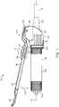
- FIG. 1 illustrates one embodiment of a powered surgical instrument 100 in accordance with aspects of the present disclosure.
- the powered surgical instrument 100 includes a housing 102 and an actuator assembly 103.
- the actuator assembly 103 includes a lever 104, an actuator 106, and a collar 108.
- the lever 104 pivotally extends away from the housing 102 as indicated by arrow 110.
- the housing 102 and the lever 104 can be grasped in a single hand of a user.
- the actuator 106 is slidably coupled on the lever 104 as indicated by arrow 111.
- the housing 102 of the powered surgical instrument 100 is generally cylindrical and extends from a first end 112 to a second end 114 along a central longitudinal axis 116.
- the first end 112 includes a back nut (see, e.g., FIG. 2 ) for attachment to a cable 120 used to provide power to the powered surgical instrument 100.
- a surgical implement (not shown) can be attached at the second end 114.
- the surgical implement can be a cutting tool, dissection tool, or other tool useful in a surgical procedure, for example.
- the on/off operation and motor speed of the surgical instrument 100 is controlled by the actuator assembly 103 fitted around the outside of the housing 102.
- the actuator assembly 103 can be removably attached to the housing 102.
- the actuator assembly 103 includes the collar 108 that is removably fitted over the housing 102.
- the lever 104 is pivotally secured to the collar 108 to extend along a length of housing 102 toward the second end 114.
- the speed of operation of the surgical instrument 100 can be varied as corresponding to the position or proximity of the lever 104 to the housing 102, as discussed in more detail below.
- the housing 102 has an outer surface 124 and an inner surface 126 defining a housing volume 128.
- the housing volume 128 is suitable to contain a plurality of control components for the surgical instrument 100.
- the control components can include a connector insert 130, a board 132, and at least one sensor 134.
- the control components work in cooperation with the lever 104 and the actuator 106 of the actuation assembly 103, as described further below.
- Electrical cables or wiring extend within the housing 102, from the motor (and cable 120), to electrically connect and operate the surgical implement, such as a cutter (not shown).
- the electrical cables can include power and control cables.
- the electrical cables, or wiring can extend through an opening 144, provided in the printed circuit board 132 or in a space provided adjacent to the printed circuit board 132.
- the cables can electrically connect from the motor to the surgical implement via a pin 146 extending through a connector insert, or opening, in the board 132.
- the pin 146 can be electrically conductive.
- the electrical wires coupled to the motor can be terminated directly at the board 132.
- the electrical wires can include three wires, one for each phase of the motor (i.e., three-phase motor).
- the pin 146 interfaces with the board 132 without extending through the board 132.
- a contact block can hold the pin 146 (or pins 146) as part of the cables inserted into the housing 102.
- the wires can extend fully through the opening 144.
- the opening 144 can be positioned at the edge 140 of the board 132 or elsewhere as appropriate.
- the pin 146 is coupled to a cable and inserted into a receptacle of a motor used to power the surgical implement. Regardless, the pin 146 can directly electrically connect to the printed circuit board 132.
- the sensor(s) 134 are mounted on the board 132 disposed in the housing 102.
- the board 132 is a printed circuit board (PCB) and can include circuitry and/or circuit board components known in the art.
- the board 132 can have a generally circular base having a first surface 136, a second surface 138 opposite the first surface 136, and an edge 140 extending between the first surface 136 and the second surface 138.
- the first surface 136 and the second surface 138 are disposed to extend perpendicular to the longitudinal axis 116.
- the sensor(s) 134 include a first sensor 134a and a second sensor 134b with the first sensor 134a disposed on the first surface 136 of the board 132 and the second sensor 134b disposed on the second surface 138 of the board 132.
- the first and second sensors 134a, 134b are centered on the board 132 and with respect to the central longitudinal axis 116.
- the circuit board 132 is disposed within the housing 102 in a location that the sensors 134 can sense, or detect, an axial component of the magnetic field of the magnet 142.
- the sensor(s) 134 can detect the same magnetic field regardless of the circumferential position of the actuator 106.
- the senor 134a is employed to provide a "run" mode for variable speed control of the rotation of the motor and attached surgical implement and the second sensor 134b can be employed to detect axial movement of the magnet 142 for deactivation of the lever 104 during non-use of the surgical instrument, for example, for safety.
- the sensor(s) 134 can be Hall Effect sensors or other appropriate sensor, for example.
- the sensor(s) 134 monitor the position of a magnet 142 internal to the actuator 106 when the actuator assembly 103 is used to control the on/off state and the speed of the motor (not shown).
- the centrally disposed sensor(s) 134 can receive magnetic field information from the actuator 106 regardless of the rotational position of the lever 104 around the circumference of the housing 102.
- the sensor(s) 134 interface with the magnet 142 of the actuator 106.
- the magnet 142, of the actuator 106 is fitted in the lever 104.
- the position of the magnet 142 is monitored by the sensor(s) 134 as an indication of the desired operating speed of the motor.
- the magnet 142 is positioned with the north-south polarity extending along a length of the lever 104, between the ends of the lever.
- the magnetic field axis direction of the magnet 142 is generally parallel to the housing 102 when the lever 104 is pivoted and pressed against the housing 102.
- Each of sensor(s) 134a, 134b is located coaxially with the longitudinal axis 146 on the printed circuit board 132.
- the sensor(s) 134 are aligned to receive only an axial component of the magnetic field generated by the actuator 154.
- each sensor 134a, 134b of the pair of sensors is disposed on an opposite side 136, 138 of the printed circuit board 132.
- the board 132 and sensor(s) 134 are positioned such that the actuator 106 can be positioned perpendicular to the sensor(s) 134, and the magnetic field axis direction of the actuator 106 parallel to the longitudinal axis of the housing 102, as described further below.
- the actuator assembly 103 includes the lever 104 mounted to the collar 108.
- the collar 108 is rotatably mounted to the housing as illustrated in FIGS. 1 and 2 .
- the lever 104 includes an elongated base 148, and a terminal end 150.
- the terminal end 150 can be extendable from the elongated base 148.
- the terminal end 150 can be slidably extendable away from the elongated base 148.
- the elongated base 148 includes a switch mounting region 152.
- a switch body 154 can be pivotally mounted to the lever 104 at the switch mounting region 152.
- the actuator 106 includes the switch body 154 and the magnet 142.
- the switch body 154 is moveably (e.g., slidably) coupled to the lever 104.
- the magnet 142 is included in the switch body 154.
- the switch body 154 includes an actuator holder 156 that houses the magnet 142 and provides a fastener passageway.
- the switch body 154 also includes an engagement member 158 that can be mated within the fastener passageway.
- the magnet 142 can be positioned in the actuator holder 156.
- the magnet 142 can be, for example, a samarium cobalt magnet, and /or a variety of other actuators know in the art.
- the switch body 154 is moveably coupled to the lever 104 by positioning the actuator holder 156 in the switch mount region 152 and positioning the engagement member 158 adjacent the top wall of the lever 104 such that bottom portion of the engagement member 158 extends through the switch mounting aperture defined by the lever 104.
- a fastener is then positioned in the fastener passageway defined by the actuator holder 156 and engaged with the fastener aperture defined by the engagement member 158 to couple the switch body 154 to the lever 104.
- the switch body 154 With the switch body 154 coupled to the lever 104, the switch body 154 can be slidingly moveable relative to the lever 104 in the switch mounting region 152.
- the actuator 106 can be locked into an activated or an inactivated position.
- the lever 104 is mounted to the collar 108 at a mounting section 160.
- the mounting section 160 includes an opening 162 at a bottom surface of the lever 104 to house a retaining member 164, such as a spring.
- the retaining member 164 couples to the lever 104 and to the collar 108 in order to pivotally connect the lever 104 to the collar 108.
- the lever 104 is coupled to the housing 102 with the collar 108.
- the collar 108 can be rotatably coupled to the housing 102, as described in more detail below.
- the collar 108 is removable from the housing 102.
- the collar 108 and is thus also the lever 104, is rotatable to any number of positions circumferentially around the housing 102.
- the collar 108 can be rotatably locked into a circumferential position with respect to the housing 102.
- a cylindrical base 166 of the collar 108 encircles the housing 102.
- the collar 108 can be removably mounted to the housing 102.
- the collar is disposed proximal to the back nut 122 and the lever 104 extends away the back nut 122.
- the collar 108 includes the cylindrical base 166 having a front edge 168 and a rear edge 170 with an interior surface 172 and an exterior surface 174 extending between the front edge 168 and rear edge 170.
- a passageway is formed at the interior surface 172.
- grooves 176 are formed along the exterior surface 174 for grasping by a user to facilitate rotating of the collar 108.
- the grooves 176 extend parallel to the longitudinal axis 116.
- the collar 108 can have holding ring indent 178 circumferentially disposed extending from the exterior surface 174 partially toward the interior surface 172.
- the holding ring indent 178 is configured to accommodate a holding ring 180 to temporarily lock the collar 108 unto the housing 102 (see, e.g., FIG. 1 ).
- the collar 108 includes a mounting channel 182 extending through the collar 108 from the interior surface 172 to the exterior surface 174.
- the mounting channel 182 can be segmented into circumferential and longitudinal portions.
- the mounting channel 182 is mateable with a nub (not shown) on the housing 102.
- the collar 108 includes a lever mount 184.
- the lever mount 184 can include a channel defined between spaced apart mounting tabs that extend outwardly from the main body of the collar 108.
- the mounting tabs 186 can extend parallel with the longitudinal axis 116.
- the mounting tabs 186 can each include an aperture 188 for mounting the lever 104.
- the collar 108 includes spaced apart mounting tabs that extend outwardly from the main body of the collar 108.
- An end 190 of the lever 104 extends between the mounting tabs 186 and is connected by a pin 192 to the mounting tabs 186.
- a resilient member 164 such as a torsion spring, is located between the collar 108 and the lever 104 so that the lever 104 is normally pivoted away from the handpiece housing 102 in an "off', or inactivated, position.
- the actuator 106 is slidably moved by a user to a "run", or activated, positioned that is sensed by the sensor 134.
- the lever 104 is pivotably movable relative to the housing 102, and the sensor 134 maintained in the housing 102, in order to vary the magnetic field strength of the magnet 142 detected by the sensor 134 and to vary a signal produced by the sensor 134 in response to the magnetic field strength detected.
- the lever 104 can be pressed by a user to pivot the lever 104 toward the handpiece in a "run", or activated, position to adjust (i.e., increase or decrease) the rotational speed of the surgical implement attached to the instrument 100.
- the lever 104 can be maintained in any position along the range indicated by arrow 110 to maintain a desired rotational speed for a desired period of time.
- the lever 104 when fully pivoted away from the housing is in the inactivated, or "off', position as detected by the sensor 134 and can be temporarily “locked” into the inactivated position.
Landscapes
- Health & Medical Sciences (AREA)
- Surgery (AREA)
- Life Sciences & Earth Sciences (AREA)
- Biomedical Technology (AREA)
- Medical Informatics (AREA)
- Veterinary Medicine (AREA)
- Public Health (AREA)
- Engineering & Computer Science (AREA)
- General Health & Medical Sciences (AREA)
- Heart & Thoracic Surgery (AREA)
- Nuclear Medicine, Radiotherapy & Molecular Imaging (AREA)
- Molecular Biology (AREA)
- Animal Behavior & Ethology (AREA)
- Orthopedic Medicine & Surgery (AREA)
- Dentistry (AREA)
- Oral & Maxillofacial Surgery (AREA)
- Surgical Instruments (AREA)
Claims (15)
- Steuerung für ein angetriebenes chirurgisches Instrument, die Steuerung umfassend:ein Gehäuse (102), das eine Mittellängsachse aufweist;einen Sensor (134); undeine Aktuatoranordnung (103),die einen Hebel (104), der mit dem Gehäuse (102) schwenkbar gekoppelt ist, einschließt, wobei der Hebel (104) einen Magneten (142) einschließt, wobei der Hebel (104) betriebsfähig ist, um den Magneten (142) relativ zu dem Sensor (134) zu bewegen, um ein Signal, das durch den Sensor (134) erzeugt wird, als Reaktion auf ein Magnetfeld des Magneten (142) zu variieren,dadurch gekennzeichnet, dass der Sensor (134) an einer Leiterplatte (132) innerhalb des Gehäuses (102) entlang der Mittellängsachse montiert ist.
- Steuerung nach Anspruch 1, wobei der Hebel (104) um die Mittellängsachse des Gehäuses (102) drehbar ist, speziell um die Mittellängsachse des Gehäuses (102) vollständig umlaufend drehbar ist.
- Steuerung nach einem der vorstehenden Ansprüche, wobei der Sensor (134) ausgerichtet ist, um eine axiale Komponente eines Magnetfelds des Magneten (142) zu erkennen.
- Steuerung nach einem der vorstehenden Ansprüche, wobei der Magnet (142) entlang einer Länge des Hebels (104) verschieblich positionierbar ist.
- Steuerung nach einem der vorstehenden Ansprüche,
wobei der Hebel (104) schwenkbar ist, um sich parallel zu dem Gehäuse (102) zu erstrecken, und/oder wobei eine Magnetfeldachse des Magneten (142) entlang einer Länge des Hebels (104) orientiert ist. - Steuerung nach einem der vorstehenden Ansprüche, wobei der Hebel (104) von dem Gehäuse (102) entfernbar ist.
- Steuerung nach einem der vorstehenden Ansprüche, wobei der Sensor (134) ein Paar Sensoren (134a, 134b) einschließt, wobei jeder von dem Paar Sensoren (134a, 134b) an einer gegenüberliegenden Oberfläche der Leiterplatte (132) mittig eingerichtet ist.
- Steuerung nach einem der vorstehenden Ansprüche, wobei sich ein Schalterkörper (154), der mit dem Magneten (142) gekoppelt ist, zu einem Äußeren des Hebels (104) erstreckt und entlang des Hebels (104) verschiebbar ist.
- Steuerung nach einem der vorstehenden Ansprüche, wobei der Magnet (142) eine Magnetfeldachse, die zu einer Länge des Hebels (104) parallel orientiert ist, aufweist.
- Steuerung nach einem der vorstehenden Ansprüche, wobei der Sensor (134) ein Hall-Effekt-Sensor ist.
- Angetriebenes chirurgisches Instrument, umfassend eine Steuerung nach einem der vorstehenden Ansprüche.
- Angetriebenes chirurgisches Instrument nach Anspruch 11, wobei der Hebel (104) und das Gehäuse (102) konfiguriert sind, um in einer einzelnen Hand eines Benutzers gefasst zu werden.
- Verfahren zum Steuern eines angetriebenen chirurgischen Instruments, das Verfahren umfassend:Schwenken eines Abschlussendes eines Hebels (104) zu einem Gehäuse (102) hin, wobei das Gehäuse (102) eine Mittellängsachse aufweist;Verschieben eines Schalters (154), der einen Aktuator (106), der mit dem Hebel (104) gekoppelt ist, aufweist, zu einer Position proximal zu einem Sensor (134), der innerhalb des Gehäuses (102) eingerichtet ist, wobei der Aktuator (106) ein Magnetfeld, das parallel zu einer Länge des Hebels (104) ist, aufweist;Erfassen eines Magnetfelds des Aktuators (106) mit dem Sensor (134); undAktivieren eines chirurgischen Werkzeugs, das mit dem angetriebenen chirurgischen Instrument gekoppelt ist, als Reaktion auf das erfasste Magnetfeld, dadurch gekennzeichnet, dass der Sensor (134) entlang der Mittellängsachse eingerichtet ist.
- Verfahren nach Anspruch 13, ferner umfassend:Umlaufendes Drehen des Hebels (104) um das Gehäuse (102) und/oderFreigeben des Hebels (104), um das Abschlussende von dem Gehäuse (102) weg zu schwenken.
- Verfahren nach einem der Ansprüche 13 oder 14, ferner umfassend:Verschieben des Schalters (154) in einer Richtung entlang des Hebels (104) weg von dem Sensor (134) undDeaktivieren des chirurgischen Werkzeugs.
Applications Claiming Priority (2)
| Application Number | Priority Date | Filing Date | Title |
|---|---|---|---|
| US15/207,755 US10548576B2 (en) | 2016-07-12 | 2016-07-12 | Control for surgical handpiece |
| PCT/US2017/037399 WO2018013281A1 (en) | 2016-07-12 | 2017-06-14 | Control for surgical handpiece |
Publications (2)
| Publication Number | Publication Date |
|---|---|
| EP3484380A1 EP3484380A1 (de) | 2019-05-22 |
| EP3484380B1 true EP3484380B1 (de) | 2023-01-18 |
Family
ID=59093648
Family Applications (1)
| Application Number | Title | Priority Date | Filing Date |
|---|---|---|---|
| EP17732008.2A Active EP3484380B1 (de) | 2016-07-12 | 2017-06-14 | Steuerung für chirurgisches handstück |
Country Status (8)
| Country | Link |
|---|---|
| US (2) | US10548576B2 (de) |
| EP (1) | EP3484380B1 (de) |
| JP (1) | JP6975179B2 (de) |
| KR (1) | KR20190028452A (de) |
| CN (1) | CN109310445B (de) |
| AU (1) | AU2017297202A1 (de) |
| CA (1) | CA3025878A1 (de) |
| WO (1) | WO2018013281A1 (de) |
Families Citing this family (6)
| Publication number | Priority date | Publication date | Assignee | Title |
|---|---|---|---|---|
| GB201504854D0 (en) * | 2015-03-23 | 2015-05-06 | Depuy Ireland | A attachment mechanism for a surgical instrument component |
| US10548576B2 (en) * | 2016-07-12 | 2020-02-04 | Medtronic Xomed, Inc. | Control for surgical handpiece |
| WO2020182273A1 (en) * | 2019-03-08 | 2020-09-17 | Mirka Oy | Trigger apparatus for powered device, powered device, and method of controlling an operation of a powered device |
| EP4304089B1 (de) * | 2019-04-12 | 2025-10-01 | Stryker European Operations Limited | Handschalter und verbinder für ein angetriebenes chirurgisches handstück |
| EP3822035A1 (de) * | 2019-11-14 | 2021-05-19 | Hilti Aktiengesellschaft | Handgriffvorrichtung für eine werkzeugmaschine |
| US11437942B2 (en) * | 2020-01-23 | 2022-09-06 | Whirlpool Corporation | Speed control assembly for appliance |
Family Cites Families (11)
| Publication number | Priority date | Publication date | Assignee | Title |
|---|---|---|---|---|
| US6017354A (en) | 1996-08-15 | 2000-01-25 | Stryker Corporation | Integrated system for powered surgical tools |
| US6650211B2 (en) | 2001-05-25 | 2003-11-18 | Asco Controls, Lp | Valve position switch |
| US7950560B2 (en) * | 2007-04-13 | 2011-05-31 | Tyco Healthcare Group Lp | Powered surgical instrument |
| US8197501B2 (en) * | 2008-03-20 | 2012-06-12 | Medtronic Xomed, Inc. | Control for a powered surgical instrument |
| US8956342B1 (en) | 2011-09-01 | 2015-02-17 | Microaire Surgical Instruments Llc | Method and device for ergonomically and ambidextrously operable surgical device |
| US9597104B2 (en) * | 2012-06-01 | 2017-03-21 | Covidien Lp | Handheld surgical handle assembly, surgical adapters for use between surgical handle assembly and surgical end effectors, and methods of use |
| US9955965B2 (en) * | 2012-07-09 | 2018-05-01 | Covidien Lp | Switch block control assembly of a medical device |
| US9421014B2 (en) * | 2012-10-18 | 2016-08-23 | Covidien Lp | Loading unit velocity and position feedback |
| US9782187B2 (en) * | 2013-01-18 | 2017-10-10 | Covidien Lp | Adapter load button lockout |
| CA2902238A1 (en) | 2013-03-15 | 2014-09-18 | Stryker Corporation | End effector of a surgical robotic manipulator |
| US10548576B2 (en) * | 2016-07-12 | 2020-02-04 | Medtronic Xomed, Inc. | Control for surgical handpiece |
-
2016
- 2016-07-12 US US15/207,755 patent/US10548576B2/en active Active
-
2017
- 2017-06-14 JP JP2018563498A patent/JP6975179B2/ja active Active
- 2017-06-14 CA CA3025878A patent/CA3025878A1/en not_active Abandoned
- 2017-06-14 EP EP17732008.2A patent/EP3484380B1/de active Active
- 2017-06-14 CN CN201780035944.4A patent/CN109310445B/zh active Active
- 2017-06-14 AU AU2017297202A patent/AU2017297202A1/en not_active Abandoned
- 2017-06-14 WO PCT/US2017/037399 patent/WO2018013281A1/en not_active Ceased
- 2017-06-14 KR KR1020197002984A patent/KR20190028452A/ko not_active Abandoned
-
2019
- 2019-10-17 US US16/655,884 patent/US11571191B2/en active Active
Also Published As
| Publication number | Publication date |
|---|---|
| JP2019521744A (ja) | 2019-08-08 |
| CN109310445B (zh) | 2021-05-28 |
| WO2018013281A1 (en) | 2018-01-18 |
| EP3484380A1 (de) | 2019-05-22 |
| JP6975179B2 (ja) | 2021-12-01 |
| US10548576B2 (en) | 2020-02-04 |
| US11571191B2 (en) | 2023-02-07 |
| CA3025878A1 (en) | 2018-01-18 |
| AU2017297202A1 (en) | 2018-12-13 |
| US20200046331A1 (en) | 2020-02-13 |
| CN109310445A (zh) | 2019-02-05 |
| US20180014820A1 (en) | 2018-01-18 |
| KR20190028452A (ko) | 2019-03-18 |
Similar Documents
| Publication | Publication Date | Title |
|---|---|---|
| US11571191B2 (en) | Control for surgical handpiece | |
| US12343067B2 (en) | Electrosurgical device | |
| US8545527B2 (en) | Control for a powered surgical instrument | |
| GB2546268A (en) | Electrosurgical device |
Legal Events
| Date | Code | Title | Description |
|---|---|---|---|
| STAA | Information on the status of an ep patent application or granted ep patent |
Free format text: STATUS: UNKNOWN |
|
| STAA | Information on the status of an ep patent application or granted ep patent |
Free format text: STATUS: THE INTERNATIONAL PUBLICATION HAS BEEN MADE |
|
| PUAI | Public reference made under article 153(3) epc to a published international application that has entered the european phase |
Free format text: ORIGINAL CODE: 0009012 |
|
| STAA | Information on the status of an ep patent application or granted ep patent |
Free format text: STATUS: REQUEST FOR EXAMINATION WAS MADE |
|
| 17P | Request for examination filed |
Effective date: 20181217 |
|
| AK | Designated contracting states |
Kind code of ref document: A1 Designated state(s): AL AT BE BG CH CY CZ DE DK EE ES FI FR GB GR HR HU IE IS IT LI LT LU LV MC MK MT NL NO PL PT RO RS SE SI SK SM TR |
|
| AX | Request for extension of the european patent |
Extension state: BA ME |
|
| DAV | Request for validation of the european patent (deleted) | ||
| DAX | Request for extension of the european patent (deleted) | ||
| STAA | Information on the status of an ep patent application or granted ep patent |
Free format text: STATUS: EXAMINATION IS IN PROGRESS |
|
| 17Q | First examination report despatched |
Effective date: 20210211 |
|
| GRAP | Despatch of communication of intention to grant a patent |
Free format text: ORIGINAL CODE: EPIDOSNIGR1 |
|
| STAA | Information on the status of an ep patent application or granted ep patent |
Free format text: STATUS: GRANT OF PATENT IS INTENDED |
|
| INTG | Intention to grant announced |
Effective date: 20220923 |
|
| RIN1 | Information on inventor provided before grant (corrected) |
Inventor name: ESTES, LARRY DALE Inventor name: LUEDI, MANFRED K. Inventor name: GARADI, VIKRAM |
|
| GRAS | Grant fee paid |
Free format text: ORIGINAL CODE: EPIDOSNIGR3 |
|
| GRAA | (expected) grant |
Free format text: ORIGINAL CODE: 0009210 |
|
| STAA | Information on the status of an ep patent application or granted ep patent |
Free format text: STATUS: THE PATENT HAS BEEN GRANTED |
|
| AK | Designated contracting states |
Kind code of ref document: B1 Designated state(s): AL AT BE BG CH CY CZ DE DK EE ES FI FR GB GR HR HU IE IS IT LI LT LU LV MC MK MT NL NO PL PT RO RS SE SI SK SM TR |
|
| REG | Reference to a national code |
Ref country code: GB Ref legal event code: FG4D |
|
| REG | Reference to a national code |
Ref country code: CH Ref legal event code: EP |
|
| REG | Reference to a national code |
Ref country code: DE Ref legal event code: R096 Ref document number: 602017065571 Country of ref document: DE |
|
| REG | Reference to a national code |
Ref country code: AT Ref legal event code: REF Ref document number: 1544256 Country of ref document: AT Kind code of ref document: T Effective date: 20230215 Ref country code: IE Ref legal event code: FG4D |
|
| REG | Reference to a national code |
Ref country code: LT Ref legal event code: MG9D |
|
| REG | Reference to a national code |
Ref country code: NL Ref legal event code: MP Effective date: 20230118 |
|
| REG | Reference to a national code |
Ref country code: AT Ref legal event code: MK05 Ref document number: 1544256 Country of ref document: AT Kind code of ref document: T Effective date: 20230118 |
|
| PG25 | Lapsed in a contracting state [announced via postgrant information from national office to epo] |
Ref country code: NL Free format text: LAPSE BECAUSE OF FAILURE TO SUBMIT A TRANSLATION OF THE DESCRIPTION OR TO PAY THE FEE WITHIN THE PRESCRIBED TIME-LIMIT Effective date: 20230118 |
|
| PG25 | Lapsed in a contracting state [announced via postgrant information from national office to epo] |
Ref country code: RS Free format text: LAPSE BECAUSE OF FAILURE TO SUBMIT A TRANSLATION OF THE DESCRIPTION OR TO PAY THE FEE WITHIN THE PRESCRIBED TIME-LIMIT Effective date: 20230118 Ref country code: PT Free format text: LAPSE BECAUSE OF FAILURE TO SUBMIT A TRANSLATION OF THE DESCRIPTION OR TO PAY THE FEE WITHIN THE PRESCRIBED TIME-LIMIT Effective date: 20230518 Ref country code: NO Free format text: LAPSE BECAUSE OF FAILURE TO SUBMIT A TRANSLATION OF THE DESCRIPTION OR TO PAY THE FEE WITHIN THE PRESCRIBED TIME-LIMIT Effective date: 20230418 Ref country code: LV Free format text: LAPSE BECAUSE OF FAILURE TO SUBMIT A TRANSLATION OF THE DESCRIPTION OR TO PAY THE FEE WITHIN THE PRESCRIBED TIME-LIMIT Effective date: 20230118 Ref country code: LT Free format text: LAPSE BECAUSE OF FAILURE TO SUBMIT A TRANSLATION OF THE DESCRIPTION OR TO PAY THE FEE WITHIN THE PRESCRIBED TIME-LIMIT Effective date: 20230118 Ref country code: HR Free format text: LAPSE BECAUSE OF FAILURE TO SUBMIT A TRANSLATION OF THE DESCRIPTION OR TO PAY THE FEE WITHIN THE PRESCRIBED TIME-LIMIT Effective date: 20230118 Ref country code: ES Free format text: LAPSE BECAUSE OF FAILURE TO SUBMIT A TRANSLATION OF THE DESCRIPTION OR TO PAY THE FEE WITHIN THE PRESCRIBED TIME-LIMIT Effective date: 20230118 Ref country code: AT Free format text: LAPSE BECAUSE OF FAILURE TO SUBMIT A TRANSLATION OF THE DESCRIPTION OR TO PAY THE FEE WITHIN THE PRESCRIBED TIME-LIMIT Effective date: 20230118 |
|
| PG25 | Lapsed in a contracting state [announced via postgrant information from national office to epo] |
Ref country code: SE Free format text: LAPSE BECAUSE OF FAILURE TO SUBMIT A TRANSLATION OF THE DESCRIPTION OR TO PAY THE FEE WITHIN THE PRESCRIBED TIME-LIMIT Effective date: 20230118 Ref country code: PL Free format text: LAPSE BECAUSE OF FAILURE TO SUBMIT A TRANSLATION OF THE DESCRIPTION OR TO PAY THE FEE WITHIN THE PRESCRIBED TIME-LIMIT Effective date: 20230118 Ref country code: IS Free format text: LAPSE BECAUSE OF FAILURE TO SUBMIT A TRANSLATION OF THE DESCRIPTION OR TO PAY THE FEE WITHIN THE PRESCRIBED TIME-LIMIT Effective date: 20230518 Ref country code: GR Free format text: LAPSE BECAUSE OF FAILURE TO SUBMIT A TRANSLATION OF THE DESCRIPTION OR TO PAY THE FEE WITHIN THE PRESCRIBED TIME-LIMIT Effective date: 20230419 Ref country code: FI Free format text: LAPSE BECAUSE OF FAILURE TO SUBMIT A TRANSLATION OF THE DESCRIPTION OR TO PAY THE FEE WITHIN THE PRESCRIBED TIME-LIMIT Effective date: 20230118 |
|
| REG | Reference to a national code |
Ref country code: DE Ref legal event code: R097 Ref document number: 602017065571 Country of ref document: DE |
|
| PG25 | Lapsed in a contracting state [announced via postgrant information from national office to epo] |
Ref country code: SM Free format text: LAPSE BECAUSE OF FAILURE TO SUBMIT A TRANSLATION OF THE DESCRIPTION OR TO PAY THE FEE WITHIN THE PRESCRIBED TIME-LIMIT Effective date: 20230118 Ref country code: RO Free format text: LAPSE BECAUSE OF FAILURE TO SUBMIT A TRANSLATION OF THE DESCRIPTION OR TO PAY THE FEE WITHIN THE PRESCRIBED TIME-LIMIT Effective date: 20230118 Ref country code: EE Free format text: LAPSE BECAUSE OF FAILURE TO SUBMIT A TRANSLATION OF THE DESCRIPTION OR TO PAY THE FEE WITHIN THE PRESCRIBED TIME-LIMIT Effective date: 20230118 Ref country code: DK Free format text: LAPSE BECAUSE OF FAILURE TO SUBMIT A TRANSLATION OF THE DESCRIPTION OR TO PAY THE FEE WITHIN THE PRESCRIBED TIME-LIMIT Effective date: 20230118 Ref country code: CZ Free format text: LAPSE BECAUSE OF FAILURE TO SUBMIT A TRANSLATION OF THE DESCRIPTION OR TO PAY THE FEE WITHIN THE PRESCRIBED TIME-LIMIT Effective date: 20230118 |
|
| PLBE | No opposition filed within time limit |
Free format text: ORIGINAL CODE: 0009261 |
|
| STAA | Information on the status of an ep patent application or granted ep patent |
Free format text: STATUS: NO OPPOSITION FILED WITHIN TIME LIMIT |
|
| PG25 | Lapsed in a contracting state [announced via postgrant information from national office to epo] |
Ref country code: SK Free format text: LAPSE BECAUSE OF FAILURE TO SUBMIT A TRANSLATION OF THE DESCRIPTION OR TO PAY THE FEE WITHIN THE PRESCRIBED TIME-LIMIT Effective date: 20230118 |
|
| 26N | No opposition filed |
Effective date: 20231019 |
|
| PG25 | Lapsed in a contracting state [announced via postgrant information from national office to epo] |
Ref country code: MC Free format text: LAPSE BECAUSE OF FAILURE TO SUBMIT A TRANSLATION OF THE DESCRIPTION OR TO PAY THE FEE WITHIN THE PRESCRIBED TIME-LIMIT Effective date: 20230118 |
|
| PG25 | Lapsed in a contracting state [announced via postgrant information from national office to epo] |
Ref country code: SI Free format text: LAPSE BECAUSE OF FAILURE TO SUBMIT A TRANSLATION OF THE DESCRIPTION OR TO PAY THE FEE WITHIN THE PRESCRIBED TIME-LIMIT Effective date: 20230118 Ref country code: MC Free format text: LAPSE BECAUSE OF FAILURE TO SUBMIT A TRANSLATION OF THE DESCRIPTION OR TO PAY THE FEE WITHIN THE PRESCRIBED TIME-LIMIT Effective date: 20230118 |
|
| REG | Reference to a national code |
Ref country code: CH Ref legal event code: PL |
|
| REG | Reference to a national code |
Ref country code: BE Ref legal event code: MM Effective date: 20230630 |
|
| GBPC | Gb: european patent ceased through non-payment of renewal fee |
Effective date: 20230614 |
|
| PG25 | Lapsed in a contracting state [announced via postgrant information from national office to epo] |
Ref country code: LU Free format text: LAPSE BECAUSE OF NON-PAYMENT OF DUE FEES Effective date: 20230614 |
|
| REG | Reference to a national code |
Ref country code: IE Ref legal event code: MM4A |
|
| PG25 | Lapsed in a contracting state [announced via postgrant information from national office to epo] |
Ref country code: LU Free format text: LAPSE BECAUSE OF NON-PAYMENT OF DUE FEES Effective date: 20230614 |
|
| PG25 | Lapsed in a contracting state [announced via postgrant information from national office to epo] |
Ref country code: IE Free format text: LAPSE BECAUSE OF NON-PAYMENT OF DUE FEES Effective date: 20230614 |
|
| PG25 | Lapsed in a contracting state [announced via postgrant information from national office to epo] |
Ref country code: IE Free format text: LAPSE BECAUSE OF NON-PAYMENT OF DUE FEES Effective date: 20230614 Ref country code: CH Free format text: LAPSE BECAUSE OF NON-PAYMENT OF DUE FEES Effective date: 20230630 Ref country code: GB Free format text: LAPSE BECAUSE OF NON-PAYMENT OF DUE FEES Effective date: 20230614 |
|
| PG25 | Lapsed in a contracting state [announced via postgrant information from national office to epo] |
Ref country code: IT Free format text: LAPSE BECAUSE OF FAILURE TO SUBMIT A TRANSLATION OF THE DESCRIPTION OR TO PAY THE FEE WITHIN THE PRESCRIBED TIME-LIMIT Effective date: 20230118 Ref country code: BE Free format text: LAPSE BECAUSE OF NON-PAYMENT OF DUE FEES Effective date: 20230630 |
|
| PG25 | Lapsed in a contracting state [announced via postgrant information from national office to epo] |
Ref country code: BG Free format text: LAPSE BECAUSE OF FAILURE TO SUBMIT A TRANSLATION OF THE DESCRIPTION OR TO PAY THE FEE WITHIN THE PRESCRIBED TIME-LIMIT Effective date: 20230118 |
|
| PG25 | Lapsed in a contracting state [announced via postgrant information from national office to epo] |
Ref country code: BG Free format text: LAPSE BECAUSE OF FAILURE TO SUBMIT A TRANSLATION OF THE DESCRIPTION OR TO PAY THE FEE WITHIN THE PRESCRIBED TIME-LIMIT Effective date: 20230118 |
|
| PGFP | Annual fee paid to national office [announced via postgrant information from national office to epo] |
Ref country code: DE Payment date: 20250520 Year of fee payment: 9 |
|
| PGFP | Annual fee paid to national office [announced via postgrant information from national office to epo] |
Ref country code: FR Payment date: 20250520 Year of fee payment: 9 |
|
| PG25 | Lapsed in a contracting state [announced via postgrant information from national office to epo] |
Ref country code: CY Free format text: LAPSE BECAUSE OF FAILURE TO SUBMIT A TRANSLATION OF THE DESCRIPTION OR TO PAY THE FEE WITHIN THE PRESCRIBED TIME-LIMIT; INVALID AB INITIO Effective date: 20170614 |
|
| PG25 | Lapsed in a contracting state [announced via postgrant information from national office to epo] |
Ref country code: HU Free format text: LAPSE BECAUSE OF FAILURE TO SUBMIT A TRANSLATION OF THE DESCRIPTION OR TO PAY THE FEE WITHIN THE PRESCRIBED TIME-LIMIT; INVALID AB INITIO Effective date: 20170614 |
|
| PG25 | Lapsed in a contracting state [announced via postgrant information from national office to epo] |
Ref country code: TR Free format text: LAPSE BECAUSE OF FAILURE TO SUBMIT A TRANSLATION OF THE DESCRIPTION OR TO PAY THE FEE WITHIN THE PRESCRIBED TIME-LIMIT Effective date: 20230118 |