EP3484005A1 - Pulse width modulation upshift at partial load to improve total harmonic cancellation performance for chiller applications - Google Patents
Pulse width modulation upshift at partial load to improve total harmonic cancellation performance for chiller applications Download PDFInfo
- Publication number
- EP3484005A1 EP3484005A1 EP18204903.1A EP18204903A EP3484005A1 EP 3484005 A1 EP3484005 A1 EP 3484005A1 EP 18204903 A EP18204903 A EP 18204903A EP 3484005 A1 EP3484005 A1 EP 3484005A1
- Authority
- EP
- European Patent Office
- Prior art keywords
- load
- frequency
- harmonics
- order
- ahf
- Prior art date
- Legal status (The legal status is an assumption and is not a legal conclusion. Google has not performed a legal analysis and makes no representation as to the accuracy of the status listed.)
- Granted
Links
Images


Classifications
-
- H—ELECTRICITY
- H02—GENERATION; CONVERSION OR DISTRIBUTION OF ELECTRIC POWER
- H02J—ELECTRIC POWER NETWORKS; CIRCUIT ARRANGEMENTS OR SYSTEMS FOR SUPPLYING OR DISTRIBUTING ELECTRIC POWER; SYSTEMS FOR STORING ELECTRIC ENERGY
- H02J3/00—Circuit arrangements for AC mains or AC distribution networks
- H02J3/01—Arrangements for reducing harmonics or ripples
-
- H—ELECTRICITY
- H02—GENERATION; CONVERSION OR DISTRIBUTION OF ELECTRIC POWER
- H02M—APPARATUS FOR CONVERSION BETWEEN AC AND AC, BETWEEN AC AND DC, OR BETWEEN DC AND DC, AND FOR USE WITH MAINS OR SIMILAR POWER SUPPLY SYSTEMS; CONVERSION OF DC OR AC INPUT POWER INTO SURGE OUTPUT POWER; CONTROL OR REGULATION THEREOF
- H02M1/00—Details of apparatus for conversion
- H02M1/12—Arrangements for reducing harmonics from AC input or output
-
- F—MECHANICAL ENGINEERING; LIGHTING; HEATING; WEAPONS; BLASTING
- F25—REFRIGERATION OR COOLING; COMBINED HEATING AND REFRIGERATION SYSTEMS; HEAT PUMP SYSTEMS; MANUFACTURE OR STORAGE OF ICE; LIQUEFACTION SOLIDIFICATION OF GASES
- F25B—REFRIGERATION MACHINES, PLANTS OR SYSTEMS; COMBINED HEATING AND REFRIGERATION SYSTEMS; HEAT PUMP SYSTEMS
- F25B49/00—Arrangement or mounting of control or safety devices
- F25B49/02—Arrangement or mounting of control or safety devices for compression type machines, plants or systems
- F25B49/025—Motor control arrangements
-
- H—ELECTRICITY
- H02—GENERATION; CONVERSION OR DISTRIBUTION OF ELECTRIC POWER
- H02J—ELECTRIC POWER NETWORKS; CIRCUIT ARRANGEMENTS OR SYSTEMS FOR SUPPLYING OR DISTRIBUTING ELECTRIC POWER; SYSTEMS FOR STORING ELECTRIC ENERGY
- H02J3/00—Circuit arrangements for AC mains or AC distribution networks
- H02J3/18—Arrangements for adjusting, eliminating or compensating reactive power in networks
- H02J3/1821—Arrangements for adjusting, eliminating or compensating reactive power in networks using shunt compensators
- H02J3/1835—Arrangements for adjusting, eliminating or compensating reactive power in networks using shunt compensators with stepless control
- H02J3/1842—Arrangements for adjusting, eliminating or compensating reactive power in networks using shunt compensators with stepless control having reactive elements actively controlled by bridge converters, e.g. active filters or static compensators [STATCOM]
-
- F—MECHANICAL ENGINEERING; LIGHTING; HEATING; WEAPONS; BLASTING
- F25—REFRIGERATION OR COOLING; COMBINED HEATING AND REFRIGERATION SYSTEMS; HEAT PUMP SYSTEMS; MANUFACTURE OR STORAGE OF ICE; LIQUEFACTION SOLIDIFICATION OF GASES
- F25B—REFRIGERATION MACHINES, PLANTS OR SYSTEMS; COMBINED HEATING AND REFRIGERATION SYSTEMS; HEAT PUMP SYSTEMS
- F25B2600/00—Control issues
- F25B2600/02—Compressor control
- F25B2600/021—Inverters therefor
-
- F—MECHANICAL ENGINEERING; LIGHTING; HEATING; WEAPONS; BLASTING
- F25—REFRIGERATION OR COOLING; COMBINED HEATING AND REFRIGERATION SYSTEMS; HEAT PUMP SYSTEMS; MANUFACTURE OR STORAGE OF ICE; LIQUEFACTION SOLIDIFICATION OF GASES
- F25B—REFRIGERATION MACHINES, PLANTS OR SYSTEMS; COMBINED HEATING AND REFRIGERATION SYSTEMS; HEAT PUMP SYSTEMS
- F25B2600/00—Control issues
- F25B2600/02—Compressor control
- F25B2600/024—Compressor control by controlling the electric parameters, e.g. current or voltage
-
- Y—GENERAL TAGGING OF NEW TECHNOLOGICAL DEVELOPMENTS; GENERAL TAGGING OF CROSS-SECTIONAL TECHNOLOGIES SPANNING OVER SEVERAL SECTIONS OF THE IPC; TECHNICAL SUBJECTS COVERED BY FORMER USPC CROSS-REFERENCE ART COLLECTIONS [XRACs] AND DIGESTS
- Y02—TECHNOLOGIES OR APPLICATIONS FOR MITIGATION OR ADAPTATION AGAINST CLIMATE CHANGE
- Y02E—REDUCTION OF GREENHOUSE GAS [GHG] EMISSIONS, RELATED TO ENERGY GENERATION, TRANSMISSION OR DISTRIBUTION
- Y02E40/00—Technologies for an efficient electrical power generation, transmission or distribution
- Y02E40/40—Arrangements for reducing harmonics
Definitions
- the subject matter disclosed herein generally relates to chillers, and more particularly, to a method and apparatus to control harmonics of variable frequency drives of chillers.
- An active harmonic filter is an analog or digital device that is installed on a coupling point to a line in parallel with a rectifier front end type variable frequency drive and is configured to measure power quality on the grid or the rectifier side and to inject current from the coupling point to the electrical grid accordingly. That is, the AHF injects the current into the line in order to compensate for any unwanted deviations from the standard current (i.e., 50 or 60 Hz supply) as found from the measurements. Such deviations can be partially mitigated or mitigated in full.
- the standard current i.e., 50 or 60 Hz supply
- the deviations may be present in the form of current harmonics.
- AHF active harmonic filter
- THD total harmonic cancellation
- a pulse width modulation (PWM) based active harmonic filter (AHF) system includes a controller configured to adjust a load on the PWM based AHF system from a first load to a second load, the first load being greater than the second load, wherein the controller is configured to adjust a frequency of the PWM based AHF system from a first frequency to a second frequency when the load is equal to the second load, and wherein the second frequency is greater than the first frequency; a first harmonic compensator configured to filter a first order of harmonics of a load when the load is equal to the second load; and a second harmonic compensator configured to filter a second order of harmonics of the load in parallel with the first order of harmonics when the load is equal to the second load and the frequency is equal to the second frequency, the second order of harmonics being greater than the first order of harmonics.
- PWM pulse width modulation
- AHF active harmonic filter
- further embodiments may include that the load includes a rectifier front end type variable frequency drive in a high tier chiller.
- a method of operating a pulse width modulation (PWM) based active harmonic filter (AHF) system including: adjusting a load on a PWM based AHF system from a first load to a second load, the first load being greater than the second load; filtering a first order of harmonics of a load when the load is equal to the second load; adjusting a frequency of the PWM based AHF system from a first frequency to a second frequency when the load is equal to the second load, wherein the second frequency is greater than the first frequency; and filtering a second order of harmonics of the load in parallel with the first order of harmonics when the frequency is equal to the second frequency, the second order of harmonics being greater than the first order of harmonics.
- PWM pulse width modulation
- AHF active harmonic filter
- further embodiments may include that the load includes a rectifier front end type variable frequency drive in a high tier chiller.
- a pulse width modulation (PWM) based active harmonic filter (AHF) system includes an input line by which upstream current is carried from a grid; an output line by which downstream current is carried toward a load; a controller configured to adjust a load on the PWM based AHF system from a first load to a second load, the first load being greater than the second load, wherein the controller is configured to adjust a frequency of the PWM based AHF system from a first frequency to a second frequency when the load is equal to the second load, and wherein the second frequency is greater than the first frequency; a first harmonic compensator configured to filter a first order of harmonics of a load when the load is equal to the second load; and a second harmonic compensator configured to filter a second order of harmonics of the load in parallel with the first order of harmonics when the load is equal to the second load and the frequency is equal to the second frequency, the second order of harmonics being greater than the first order of harmonics.
- PWM pulse width modulation
- AHF active harmonic filter
- further embodiments may include that the grid includes an electrical grid and the load comprises a rectifier front end type variable frequency drive in a high tier chiller.
- FIG. 1 depicts a chiller system 10 in an exemplary embodiment.
- Chiller system 10 is a screw chiller, but embodiments of the invention are appropriate for use with other compression chiller assemblies, such as, for example, a centrifugal chiller.
- chiller system 10 includes compressor 12, variable frequency drive 14, condenser 16, and cooler 18.
- variable frequency drive 14 controls the frequency of the alternating current (AC) supplied to the motor thereby controlling the speed of the motor and the output of compressor 12.
- AC alternating current
- condenser 16 the gaseous refrigerant condenses into liquid as it gives up heat.
- the condensed liquid refrigerant then flows into cooler 18, which circulates chilled water.
- the low pressure environment in cooler 18 causes the refrigerant to change states to a gas and, as it does so, it absorbs the required heat of vaporization from the chilled water, thus reducing the temperature of the water.
- the low pressure vapor is then drawn into the inlet of compressor 12 and the cycle is continually repeated.
- the chilled water is circulated through a distribution system to cooling coils for, for example, comfort air conditioning to cool an inside location separated from an outside location.
- Portions of the chiller system 10 may operate at a low pressure (e.g., less than atmosphere) which can cause non-condensables (e.g., ambient air) to be drawn into the chiller system 10.
- a low pressure e.g., less than atmosphere
- non-condensables e.g., ambient air
- a system which increases the pulse width modulation (PWM) switching frequency at partial load and also adds a higher order harmonic regulator with the higher PWM switching frequency.
- PWM pulse width modulation
- AHFs active harmonic filters
- the AHF total current is also reduced with the reduced load, thus allowing a controller to increase the switching frequency without thermal issues and also add the higher order harmonic regulator which can cancel more high order harmonics elements and improve the overall total harmonic cancellation (THD) performance.
- a pulse width modulations (PWM) based active harmonic filter (AHF) system 110 is provided and includes an input line 111, an output line 112, an active harmonic filter (AHF) 113, a controller 115, an electrical grid 120, a load 130, such as a rectifier front end type variable frequency drive 301 in a high tier chiller 10 (see FIG. 1 ).
- PWM pulse width modulations
- AHF active harmonic filter
- controller 115 includes an input line 111, an output line 112, an active harmonic filter (AHF) 113, a controller 115, an electrical grid 120, a load 130, such as a rectifier front end type variable frequency drive 301 in a high tier chiller 10 (see FIG. 1 ).
- Upstream current is carried from the electrical grid 120, along the input line 111 to the AHF 113 and to the load 130 as downstream current along the output line 112.
- the AHF 113 may be, but is not required to be, configured to measure a characteristic of the upstream current carried by and along the input line 111, such as a deviation from a standard frequency, and to execute PWM based on results of that measurement to thereby affect the characteristic of the downstream current on the output line 112. In so doing, the AHF 113 may tend to generate and develop ripple effects in the upstream current which may propagate undesirably towards the electrical grid 120.
- the controller 115 is operably coupled to the AHF 113 and is configured to control the PWM of the AHF 113.
- the harmonic compensators 210, 220 may include a first harmonic compensator 210 and a second order harmonic compensator 220.
- the second order harmonic compensator 220 may be utilized in addition to the first order harmonic compensator 210 at partial load.
- an original harmonic order will be compensated by the first harmonic compensator 210, while the second order harmonic compensator 220 may compensate, in parallel, an additional harmonic of a higher order than the original harmonic.
- the controller 115 is configured to adjust a load on the PWM based AHF system 110 from a first load to a second load based on an inside temperature of an inside location, an outside temperature of an outside location separated from the inside location, and cooling requests from thermostats.
- the cooling requests may instruct the controller 115 to cool the inside location relative to the outside location, such that the inside temperature is lower than the outside temperature.
- the first load is greater than the second load.
- the second load is a partial load.
- the controller 115 is configured to adjust a frequency of the PWM based AHF system 110 from a first frequency to a second frequency when the load is equal to the second load.
- the second frequency is greater than the first frequency.
- the first harmonic compensator 210 is configured to filter a first order of harmonics of a load when the load is equal to the second load.
- the second harmonic compensator 220 is configured to filter a second order of harmonics of the load in parallel when the load is equal to the second load and the frequency is equal to the second frequency.
- the second order of harmonics is greater than the first order of harmonics in frequency.
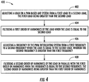
- FIG. 4 shows a flow chart of method 400 of operating a PWM based active harmonic filter (AHF) system 110, in accordance with an embodiment of the present disclosure.
- AHF active harmonic filter
- embodiments can be in the form of processor-implemented processes and devices for practicing those processes, such as a processor.
- Embodiments can also be in the form of computer program code containing instructions embodied in tangible media, such as network cloud storage, SD cards, flash drives, floppy diskettes, CD ROMs, hard drives, or any other computer-readable storage medium, wherein, when the computer program code is loaded into and executed by a computer, the computer becomes a device for practicing the embodiments.
- Embodiments can also be in the form of computer program code, for example, whether stored in a storage medium, loaded into and/or executed by a computer, or transmitted over some transmission medium, loaded into and/or executed by a computer, or transmitted over some transmission medium, such as over electrical wiring or cabling, through fiber optics, or via electromagnetic radiation, wherein, when the computer program code is loaded into an executed by a computer, the computer becomes an device for practicing the embodiments.
- the computer program code segments configure the microprocessor to create specific logic circuits.
Landscapes
- Engineering & Computer Science (AREA)
- Power Engineering (AREA)
- Physics & Mathematics (AREA)
- Mechanical Engineering (AREA)
- Thermal Sciences (AREA)
- General Engineering & Computer Science (AREA)
- Supply And Distribution Of Alternating Current (AREA)
Abstract
Description
- The subject matter disclosed herein generally relates to chillers, and more particularly, to a method and apparatus to control harmonics of variable frequency drives of chillers.
- An active harmonic filter (AHF) is an analog or digital device that is installed on a coupling point to a line in parallel with a rectifier front end type variable frequency drive and is configured to measure power quality on the grid or the rectifier side and to inject current from the coupling point to the electrical grid accordingly. That is, the AHF injects the current into the line in order to compensate for any unwanted deviations from the standard current (i.e., 50 or 60 Hz supply) as found from the measurements. Such deviations can be partially mitigated or mitigated in full.
- In some cases, such as those where the load includes a rectifier front end type variable frequency drive in high tier chiller applications, the deviations may be present in the form of current harmonics. Here, when an active harmonic filter (AHF) is used to reduce current harmonics on the AC grid side connected in parallel with rectifier front end type variable frequency drives for high-tier chiller applications, it normally achieves best total harmonic cancellation (THD) performance at full load conditions. The THD level will increase at partial load conditions due to higher current distortion ratio at partial load conditions
- According to one embodiment, a pulse width modulation (PWM) based active harmonic filter (AHF) system is provided. The PWM AHF system includes a controller configured to adjust a load on the PWM based AHF system from a first load to a second load, the first load being greater than the second load, wherein the controller is configured to adjust a frequency of the PWM based AHF system from a first frequency to a second frequency when the load is equal to the second load, and wherein the second frequency is greater than the first frequency; a first harmonic compensator configured to filter a first order of harmonics of a load when the load is equal to the second load; and a second harmonic compensator configured to filter a second order of harmonics of the load in parallel with the first order of harmonics when the load is equal to the second load and the frequency is equal to the second frequency, the second order of harmonics being greater than the first order of harmonics.
- In addition to one or more of the features described above, or as an alternative, further embodiments may include that the load includes a rectifier front end type variable frequency drive in a high tier chiller.
- According to another embodiment, a method of operating a pulse width modulation (PWM) based active harmonic filter (AHF) system is provided. The method including: adjusting a load on a PWM based AHF system from a first load to a second load, the first load being greater than the second load; filtering a first order of harmonics of a load when the load is equal to the second load; adjusting a frequency of the PWM based AHF system from a first frequency to a second frequency when the load is equal to the second load, wherein the second frequency is greater than the first frequency; and filtering a second order of harmonics of the load in parallel with the first order of harmonics when the frequency is equal to the second frequency, the second order of harmonics being greater than the first order of harmonics.
- In addition to one or more of the features described above, or as an alternative, further embodiments may include that the load includes a rectifier front end type variable frequency drive in a high tier chiller.
- According to another embodiment, a pulse width modulation (PWM) based active harmonic filter (AHF) system is provided. The PWM AHF system includes an input line by which upstream current is carried from a grid; an output line by which downstream current is carried toward a load; a controller configured to adjust a load on the PWM based AHF system from a first load to a second load, the first load being greater than the second load, wherein the controller is configured to adjust a frequency of the PWM based AHF system from a first frequency to a second frequency when the load is equal to the second load, and wherein the second frequency is greater than the first frequency; a first harmonic compensator configured to filter a first order of harmonics of a load when the load is equal to the second load; and a second harmonic compensator configured to filter a second order of harmonics of the load in parallel with the first order of harmonics when the load is equal to the second load and the frequency is equal to the second frequency, the second order of harmonics being greater than the first order of harmonics.
- In addition to one or more of the features described above, or as an alternative, further embodiments may include that the grid includes an electrical grid and the load comprises a rectifier front end type variable frequency drive in a high tier chiller.
- Technical effects of embodiments of the present disclosure include achieving a reduction of higher harmonics utilizing harmonic compensators and increasing frequency of pulse width modulation while decreasing load.
- The foregoing features and elements may be combined in various combinations without exclusivity, unless expressly indicated otherwise. These features and elements as well as the operation thereof will become more apparent in light of the following description and the accompanying drawings. It should be understood, however, that the following description and drawings are intended to be illustrative and explanatory in nature and non-limiting.
- The following descriptions should not be considered limiting in any way. With reference to the accompanying drawings, like elements are numbered alike:
-
FIG. 1 schematically illustrates an isometric view of a chiller, in accordance with an embodiment of the disclosure; -
FIG. 2 schematically illustrates a schematic illustration of a pulse width modulation (PWM) based active harmonic filter (AHF)system, in accordance with an embodiment of the disclosure; -
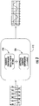
FIG. 3 schematically illustrates a software schematic illustration of an active harmonic filters (AHF) shown with the addition of one or more harmonic compensators, in accordance with an embodiment of the disclosure; and -
FIG. 4 illustrates a flow diagram illustrating a method of operating a PWM based active harmonic filter (AHF) system, according to an embodiment of the present disclosure. - A detailed description of one or more embodiments of the disclosed apparatus and method are presented herein by way of exemplification and not limitation with reference to the Figures.
-
FIG. 1 depicts achiller system 10 in an exemplary embodiment.Chiller system 10 is a screw chiller, but embodiments of the invention are appropriate for use with other compression chiller assemblies, such as, for example, a centrifugal chiller. As shown inFIG. 1 ,chiller system 10 includescompressor 12,variable frequency drive 14,condenser 16, andcooler 18. - In operation, gaseous refrigerant is induced into
compressor 12 and compressed.Compressor 12 is driven by a motor under the control ofvariable frequency drive 14.Variable frequency drive 14 controls the frequency of the alternating current (AC) supplied to the motor thereby controlling the speed of the motor and the output ofcompressor 12. After the refrigerant is compressed, the high temperature, high pressure refrigerant gas is supplied to condenser 16. Incondenser 16, the gaseous refrigerant condenses into liquid as it gives up heat. The condensed liquid refrigerant then flows intocooler 18, which circulates chilled water. The low pressure environment incooler 18 causes the refrigerant to change states to a gas and, as it does so, it absorbs the required heat of vaporization from the chilled water, thus reducing the temperature of the water. The low pressure vapor is then drawn into the inlet ofcompressor 12 and the cycle is continually repeated. The chilled water is circulated through a distribution system to cooling coils for, for example, comfort air conditioning to cool an inside location separated from an outside location. - Portions of the chiller system 10 (e.g., cooler 18) may operate at a low pressure (e.g., less than atmosphere) which can cause non-condensables (e.g., ambient air) to be drawn into the
chiller system 10. The non-condensables in the refrigerant flow of thechiller system 10 degrades performance of the chiller. - As will be described below, a system is provided which increases the pulse width modulation (PWM) switching frequency at partial load and also adds a higher order harmonic regulator with the higher PWM switching frequency. At full load, due to thermal limitation, active harmonic filters (AHFs) can only run at lower PWM switching frequency. A lower switching frequency will also not have enough control bandwidth to cancel higher order harmonics elements. Advantageously, at partial load, the AHF total current is also reduced with the reduced load, thus allowing a controller to increase the switching frequency without thermal issues and also add the higher order harmonic regulator which can cancel more high order harmonics elements and improve the overall total harmonic cancellation (THD) performance.
- With reference to
FIG. 2 , avariable frequency drive 14 is shown. A pulse width modulations (PWM) based active harmonic filter (AHF)system 110 is provided and includes aninput line 111, anoutput line 112, an active harmonic filter (AHF) 113, acontroller 115, anelectrical grid 120, aload 130, such as a rectifier front end typevariable frequency drive 301 in a high tier chiller 10 (seeFIG. 1 ). Upstream current is carried from theelectrical grid 120, along theinput line 111 to theAHF 113 and to theload 130 as downstream current along theoutput line 112. - The
AHF 113 may be, but is not required to be, configured to measure a characteristic of the upstream current carried by and along theinput line 111, such as a deviation from a standard frequency, and to execute PWM based on results of that measurement to thereby affect the characteristic of the downstream current on theoutput line 112. In so doing, the AHF 113 may tend to generate and develop ripple effects in the upstream current which may propagate undesirably towards theelectrical grid 120. As such, thecontroller 115 is operably coupled to theAHF 113 and is configured to control the PWM of theAHF 113. - Referring to
FIG. 3 with continued reference toFIG. 1 and2 , a software schematic of the AHF 113 is shown with the addition of one or moreharmonic compensators harmonic compensators harmonic compensator 210 and a second orderharmonic compensator 220. The second orderharmonic compensator 220 may be utilized in addition to the first orderharmonic compensator 210 at partial load. When both the firstharmonic compensator 210 and the second orderharmonic compensator 220 are in operation, an original harmonic order will be compensated by the firstharmonic compensator 210, while the second orderharmonic compensator 220 may compensate, in parallel, an additional harmonic of a higher order than the original harmonic. Thecontroller 115 is configured to adjust a load on the PWM basedAHF system 110 from a first load to a second load based on an inside temperature of an inside location, an outside temperature of an outside location separated from the inside location, and cooling requests from thermostats. The cooling requests may instruct thecontroller 115 to cool the inside location relative to the outside location, such that the inside temperature is lower than the outside temperature. The first load is greater than the second load. In an embodiment the second load is a partial load. Thecontroller 115 is configured to adjust a frequency of the PWM basedAHF system 110 from a first frequency to a second frequency when the load is equal to the second load. The second frequency is greater than the first frequency. The firstharmonic compensator 210 is configured to filter a first order of harmonics of a load when the load is equal to the second load. The secondharmonic compensator 220 is configured to filter a second order of harmonics of the load in parallel when the load is equal to the second load and the frequency is equal to the second frequency. The second order of harmonics is greater than the first order of harmonics in frequency. Advantageously, by thecontroller 115 reducing the load from the first load to the second load and increasing the frequency from the first frequency to the second frequency allows for allows for additional harmonics to be filtered out by the secondharmonic compensator 220. - Referring now to
FIG. 4 , with continued reference toFIGs. 1-3 .FIG. 4 shows a flow chart ofmethod 400 of operating a PWM based active harmonic filter (AHF)system 110, in accordance with an embodiment of the present disclosure. Atblock 402, a load on a PWM basedAHF system 110 is adjusted from a first load to a second load. The first load is greater than the second load. Atblock 404, a first order of harmonics of a load is filtered when the load is equal to the second load. Atblock 406, a frequency of the PWM basedAHF system 110 is adjusted from a first frequency to a second frequency when the load is equal to the second load. The second frequency is greater than the first frequency. Atblock 408, a second order of harmonics of the load is filtered when the frequency is equal to the second frequency. The second order of harmonics is greater than the first order of harmonics. - While the above description has described the flow process of
FIG. 4 in a particular order, it should be appreciated that unless otherwise specifically required in the attached claims that the ordering of the steps may be varied. - As described above, embodiments can be in the form of processor-implemented processes and devices for practicing those processes, such as a processor. Embodiments can also be in the form of computer program code containing instructions embodied in tangible media, such as network cloud storage, SD cards, flash drives, floppy diskettes, CD ROMs, hard drives, or any other computer-readable storage medium, wherein, when the computer program code is loaded into and executed by a computer, the computer becomes a device for practicing the embodiments. Embodiments can also be in the form of computer program code, for example, whether stored in a storage medium, loaded into and/or executed by a computer, or transmitted over some transmission medium, loaded into and/or executed by a computer, or transmitted over some transmission medium, such as over electrical wiring or cabling, through fiber optics, or via electromagnetic radiation, wherein, when the computer program code is loaded into an executed by a computer, the computer becomes an device for practicing the embodiments. When implemented on a general-purpose microprocessor, the computer program code segments configure the microprocessor to create specific logic circuits.
- The term "about" is intended to include the degree of error associated with measurement of the particular quantity based upon the equipment available at the time of filing the application. For example, "about" can include a range of ± 8% or 5%, or 2% of a given value.
- The terminology used herein is for the purpose of describing particular embodiments only and is not intended to be limiting of the present disclosure. As used herein, the singular forms "a", "an" and "the" are intended to include the plural forms as well, unless the context clearly indicates otherwise. It will be further understood that the terms "comprises" and/or "comprising," when used in this specification, specify the presence of stated features, integers, steps, operations, elements, and/or components, but do not preclude the presence or addition of one or more other features, integers, steps, operations, element components, and/or groups thereof.
- While the present disclosure has been described with reference to an exemplary embodiment or embodiments, it will be understood by those skilled in the art that various changes may be made and equivalents may be substituted for elements thereof without departing from the scope of the present disclosure. In addition, many modifications may be made to adapt a particular situation or material to the teachings of the present disclosure without departing from the essential scope thereof. Therefore, it is intended that the present disclosure not be limited to the particular embodiment disclosed as the best mode contemplated for carrying out this present disclosure, but that the present disclosure will include all embodiments falling within the scope of the claims.
Claims (6)
- A pulse width modulation (PWM) based active harmonic filter (AHF) system, comprising:a controller configured to adjust a load on the PWM based AHF system from a first load to a second load, the first load being greater than the second load, wherein the controller is configured to adjust a frequency of the PWM based AHF system from a first frequency to a second frequency when the load is equal to the second load, and wherein the second frequency is greater than the first frequency;a first harmonic compensator configured to filter a first order of harmonics of a load when the load is equal to the second load; anda second harmonic compensator configured to filter a second order of harmonics of the load in parallel with the first order of harmonics when the load is equal to the second load and the frequency is equal to the second frequency, the second order of harmonics being greater than the first order of harmonics.
- The PWM based AHF system according to claim 1, wherein the load comprises a rectifier front end type variable frequency drive in a high tier chiller.
- A method of operating a pulse width modulation (PWM) based active harmonic filter (AHF) system, the method comprising:adjusting a load on a PWM based AHF system from a first load to a second load, the first load being greater than the second load;filtering a first order of harmonics of a load when the load is equal to the second load;adjusting a frequency of the PWM based AHF system from a first frequency to a second frequency when the load is equal to the second load, wherein the second frequency is greater than the first frequency; andfiltering a second order of harmonics of the load in parallel with the first order of harmonics when the frequency is equal to the second frequency, the second order of harmonics being greater than the first order of harmonics.
- The method according to claim 3, wherein the load comprises a rectifier front end type variable frequency drive in a high tier chiller.
- A pulse width modulation (PWM) based active harmonic filter (AHF) system, comprising:an input line by which upstream current is carried from a grid;an output line by which downstream current is carried toward a load;a controller configured to adjust a load on the PWM based AHF system from a first load to a second load, the first load being greater than the second load, wherein the controller is configured to adjust a frequency of the PWM based AHF system from a first frequency to a second frequency when the load is equal to the second load, and wherein the second frequency is greater than the first frequency;a first harmonic compensator configured to filter a first order of harmonics of a load when the load is equal to the second load; anda second harmonic compensator configured to filter a second order of harmonics of the load in parallel with the first order of harmonics when the load is equal to the second load and the frequency is equal to the second frequency, the second order of harmonics being greater than the first order of harmonics.
- The PWM based AHF system according to claim 5, wherein the grid comprises an electrical grid and the load comprises a rectifier front end type variable frequency drive in a high tier chiller.
Applications Claiming Priority (1)
| Application Number | Priority Date | Filing Date | Title |
|---|---|---|---|
| US201762583213P | 2017-11-08 | 2017-11-08 |
Publications (2)
| Publication Number | Publication Date |
|---|---|
| EP3484005A1 true EP3484005A1 (en) | 2019-05-15 |
| EP3484005B1 EP3484005B1 (en) | 2022-06-08 |
Family
ID=64183955
Family Applications (1)
| Application Number | Title | Priority Date | Filing Date |
|---|---|---|---|
| EP18204903.1A Active EP3484005B1 (en) | 2017-11-08 | 2018-11-07 | Pulse width modulation upshift at partial load to improve total harmonic cancellation performance for chiller applications |
Country Status (4)
| Country | Link |
|---|---|
| US (1) | US10554116B2 (en) |
| EP (1) | EP3484005B1 (en) |
| CN (1) | CN109755939B (en) |
| ES (1) | ES2926224T3 (en) |
Families Citing this family (1)
| Publication number | Priority date | Publication date | Assignee | Title |
|---|---|---|---|---|
| EP3688868A1 (en) * | 2017-09-28 | 2020-08-05 | Carrier Corporation | Pulse width modulation interleaving |
Citations (2)
| Publication number | Priority date | Publication date | Assignee | Title |
|---|---|---|---|---|
| WO2011124223A2 (en) * | 2010-04-06 | 2011-10-13 | Danfoss Drives A/S | Power quality improvement by active filter |
| JP2017011778A (en) * | 2015-06-17 | 2017-01-12 | 株式会社富士通ゼネラル | Air conditioner |
Family Cites Families (20)
| Publication number | Priority date | Publication date | Assignee | Title |
|---|---|---|---|---|
| JPH01152969A (en) | 1987-12-07 | 1989-06-15 | Toshiba Corp | Control device for inverter |
| ES2071730T3 (en) * | 1990-12-10 | 1995-07-01 | Asea Brown Boveri | PROCEDURE AND DEVICE FOR THE ELIMINATION OR REDUCTION OF HARMONICS AND / OR OF RESONANCE OSCILLATIONS. |
| US5513090A (en) * | 1994-11-15 | 1996-04-30 | Electric Power Research Institute, Inc. | Hybrid series active, parallel passive, power line conditioner for harmonic isolation between a supply and a load |
| US5731965A (en) | 1996-06-21 | 1998-03-24 | Wisconsin Alumni Research Foundation | Power line harmonic reduction by hybrid parallel active/passive filter system with square wave inverter and DC bus control |
| CA2212504C (en) | 1996-08-09 | 2004-11-16 | Mesta Electronics, Inc. | Active harmonic filter and power factor corrector |
| DE19819869C2 (en) | 1998-04-27 | 2001-06-21 | Ruediger Bredtmann | Process for the compensation of current harmonics in electrical energy networks with compatibility level control |
| US6091940A (en) * | 1998-10-21 | 2000-07-18 | Parkervision, Inc. | Method and system for frequency up-conversion |
| TWI247475B (en) * | 2002-03-11 | 2006-01-11 | Uis Abler Electronics Co Ltd | An active harmonic suppression equipment and control algorithm |
| US6774758B2 (en) | 2002-09-11 | 2004-08-10 | Kalyan P. Gokhale | Low harmonic rectifier circuit |
| US8476873B2 (en) | 2009-08-10 | 2013-07-02 | Emerson Climate Technologies, Inc. | System and method for current balancing |
| US8941365B2 (en) | 2011-08-16 | 2015-01-27 | Texas Instruments Incorporated | Methods and apparatus to improve power factor at light-load |
| CN202395445U (en) * | 2011-11-03 | 2012-08-22 | 东南大学 | Multi-machine full compensation and fractional compensation combination type completely active harmonic treatment device |
| US8994346B2 (en) | 2012-02-09 | 2015-03-31 | Dell Products Lp | Systems and methods for dynamic management of switching frequency for voltage regulation |
| WO2014026124A1 (en) | 2012-08-10 | 2014-02-13 | Emerson Climate Technologies, Inc. | Motor drive control using pulse-width modulation pulse skipping |
| GB2521968B (en) | 2012-10-10 | 2018-10-10 | Trane Int Inc | Variable fan speed control in HVAC systems and methods |
| US9146045B2 (en) | 2013-08-07 | 2015-09-29 | Climacool Corp | Modular chiller system comprising interconnected flooded heat exchangers |
| US9866108B2 (en) | 2014-10-08 | 2018-01-09 | Power Intergrations, Inc. | PFC shutdown circuit for light load |
| US9887616B2 (en) | 2015-07-01 | 2018-02-06 | Hella Corporate Center Usa, Inc. | Electric power conversion apparatus with active filter |
| CN106602558A (en) * | 2016-12-02 | 2017-04-26 | 安徽波维电子科技有限公司 | Parallel active filter control system |
| CN206402112U (en) | 2016-12-27 | 2017-08-11 | 厦门理工学院 | Bank electricity system high power frequency conversion power supply based on 36 pulse wave rectifiers |
-
2018
- 2018-11-07 EP EP18204903.1A patent/EP3484005B1/en active Active
- 2018-11-07 US US16/182,792 patent/US10554116B2/en active Active
- 2018-11-07 ES ES18204903T patent/ES2926224T3/en active Active
- 2018-11-07 CN CN201811317600.5A patent/CN109755939B/en active Active
Patent Citations (2)
| Publication number | Priority date | Publication date | Assignee | Title |
|---|---|---|---|---|
| WO2011124223A2 (en) * | 2010-04-06 | 2011-10-13 | Danfoss Drives A/S | Power quality improvement by active filter |
| JP2017011778A (en) * | 2015-06-17 | 2017-01-12 | 株式会社富士通ゼネラル | Air conditioner |
Non-Patent Citations (1)
| Title |
|---|
| WANG LEI ET AL: "An adaptive hysteresis band controller for LC-coupling hybrid active power filter with approximate constant switching frequency", 2014 IEEE PES ASIA-PACIFIC POWER AND ENERGY ENGINEERING CONFERENCE (APPEEC), IEEE, 7 December 2014 (2014-12-07), pages 1 - 5, XP032752821, DOI: 10.1109/APPEEC.2014.7065993 * |
Also Published As
| Publication number | Publication date |
|---|---|
| CN109755939A (en) | 2019-05-14 |
| ES2926224T3 (en) | 2022-10-24 |
| US10554116B2 (en) | 2020-02-04 |
| CN109755939B (en) | 2024-05-28 |
| EP3484005B1 (en) | 2022-06-08 |
| US20190140535A1 (en) | 2019-05-09 |
Similar Documents
| Publication | Publication Date | Title |
|---|---|---|
| EP3228958B1 (en) | Linkage control method and apparatus for indoor and outdoor units of precision air conditioner | |
| CN106121982B (en) | Compressor control method and device, the convertible frequency air-conditioner of convertible frequency air-conditioner | |
| JP7685950B2 (en) | Oil-injected multi-stage compressor system and procedure for controlling such a compressor system | |
| JP2019083030A (en) | Extremum-seeking control system for chilled water plant and extremum-seeking controller | |
| US20150354849A1 (en) | Heat source system, and device and method for controlling cooling water supply device | |
| US20150000636A1 (en) | Method And System For Adjusting Engine Speed In A Transport Refrigeration System | |
| WO2019153887A1 (en) | Control method and device for air conditioning system and air conditioning system | |
| US11686511B2 (en) | Motor temperature control technique with temperature override | |
| BR112016027833B1 (en) | REFRIGERATION APPLIANCE AND PROCESS FOR OPERATING A REFRIGERATION APPLIANCE | |
| CN107407506A (en) | Control device and method for refrigeration cycle device | |
| US10554116B2 (en) | Pulse width modulation upshift at partial load to improve total harmonic cancellation performance for chiller applications | |
| CN107525319B (en) | Air conditioning control system and air conditioning control method | |
| CN105864920A (en) | Light-load dehumidification method and air conditioner | |
| JP2014219147A (en) | Temperature controller | |
| US11060776B2 (en) | Method for controlling a refrigeration device | |
| CN110326194B (en) | control device | |
| RU2723109C2 (en) | Cooling power capacity control during natural gas liquefaction | |
| JP2011094937A (en) | Primary pump system heat source variable flow rate control system and method | |
| CN106996713A (en) | A kind of constant temperature cooperative control method of many water cooling towers of multi fan | |
| CN113365467B (en) | Air-cooled motor controller for controlling at least one electric motor and method for controlling a fan of a corresponding motor controller | |
| US11815300B2 (en) | Chiller system and a method for generating coordination maps for energy efficient chilled water and condenser water temperature resets in chiller plant system | |
| CN118775233B (en) | Air compressor exhaust temperature control method based on intake air temperature and humidity | |
| RU2690541C2 (en) | Gas air-cooling apparatus control system | |
| CN116552193A (en) | Electric compressor segmental control method and device based on CO2 heat pump system | |
| Burba | Improved energy efficiency of air cooled chillers |
Legal Events
| Date | Code | Title | Description |
|---|---|---|---|
| PUAI | Public reference made under article 153(3) epc to a published international application that has entered the european phase |
Free format text: ORIGINAL CODE: 0009012 |
|
| STAA | Information on the status of an ep patent application or granted ep patent |
Free format text: STATUS: THE APPLICATION HAS BEEN PUBLISHED |
|
| AK | Designated contracting states |
Kind code of ref document: A1 Designated state(s): AL AT BE BG CH CY CZ DE DK EE ES FI FR GB GR HR HU IE IS IT LI LT LU LV MC MK MT NL NO PL PT RO RS SE SI SK SM TR |
|
| AX | Request for extension of the european patent |
Extension state: BA ME |
|
| STAA | Information on the status of an ep patent application or granted ep patent |
Free format text: STATUS: REQUEST FOR EXAMINATION WAS MADE |
|
| 17P | Request for examination filed |
Effective date: 20191114 |
|
| RBV | Designated contracting states (corrected) |
Designated state(s): AL AT BE BG CH CY CZ DE DK EE ES FI FR GB GR HR HU IE IS IT LI LT LU LV MC MK MT NL NO PL PT RO RS SE SI SK SM TR |
|
| RIC1 | Information provided on ipc code assigned before grant |
Ipc: H02J 3/18 20060101ALI20211007BHEP Ipc: H02J 3/01 20060101AFI20211007BHEP |
|
| GRAP | Despatch of communication of intention to grant a patent |
Free format text: ORIGINAL CODE: EPIDOSNIGR1 |
|
| STAA | Information on the status of an ep patent application or granted ep patent |
Free format text: STATUS: GRANT OF PATENT IS INTENDED |
|
| INTG | Intention to grant announced |
Effective date: 20220124 |
|
| GRAS | Grant fee paid |
Free format text: ORIGINAL CODE: EPIDOSNIGR3 |
|
| GRAA | (expected) grant |
Free format text: ORIGINAL CODE: 0009210 |
|
| STAA | Information on the status of an ep patent application or granted ep patent |
Free format text: STATUS: THE PATENT HAS BEEN GRANTED |
|
| AK | Designated contracting states |
Kind code of ref document: B1 Designated state(s): AL AT BE BG CH CY CZ DE DK EE ES FI FR GB GR HR HU IE IS IT LI LT LU LV MC MK MT NL NO PL PT RO RS SE SI SK SM TR |
|
| REG | Reference to a national code |
Ref country code: AT Ref legal event code: REF Ref document number: 1497581 Country of ref document: AT Kind code of ref document: T Effective date: 20220615 Ref country code: CH Ref legal event code: EP |
|
| REG | Reference to a national code |
Ref country code: DE Ref legal event code: R096 Ref document number: 602018036437 Country of ref document: DE |
|
| REG | Reference to a national code |
Ref country code: IE Ref legal event code: FG4D |
|
| REG | Reference to a national code |
Ref country code: NL Ref legal event code: FP |
|
| REG | Reference to a national code |
Ref country code: LT Ref legal event code: MG9D |
|
| REG | Reference to a national code |
Ref country code: ES Ref legal event code: FG2A Ref document number: 2926224 Country of ref document: ES Kind code of ref document: T3 Effective date: 20221024 |
|
| PG25 | Lapsed in a contracting state [announced via postgrant information from national office to epo] |
Ref country code: SE Free format text: LAPSE BECAUSE OF FAILURE TO SUBMIT A TRANSLATION OF THE DESCRIPTION OR TO PAY THE FEE WITHIN THE PRESCRIBED TIME-LIMIT Effective date: 20220608 Ref country code: NO Free format text: LAPSE BECAUSE OF FAILURE TO SUBMIT A TRANSLATION OF THE DESCRIPTION OR TO PAY THE FEE WITHIN THE PRESCRIBED TIME-LIMIT Effective date: 20220908 Ref country code: LT Free format text: LAPSE BECAUSE OF FAILURE TO SUBMIT A TRANSLATION OF THE DESCRIPTION OR TO PAY THE FEE WITHIN THE PRESCRIBED TIME-LIMIT Effective date: 20220608 Ref country code: HR Free format text: LAPSE BECAUSE OF FAILURE TO SUBMIT A TRANSLATION OF THE DESCRIPTION OR TO PAY THE FEE WITHIN THE PRESCRIBED TIME-LIMIT Effective date: 20220608 Ref country code: GR Free format text: LAPSE BECAUSE OF FAILURE TO SUBMIT A TRANSLATION OF THE DESCRIPTION OR TO PAY THE FEE WITHIN THE PRESCRIBED TIME-LIMIT Effective date: 20220909 Ref country code: FI Free format text: LAPSE BECAUSE OF FAILURE TO SUBMIT A TRANSLATION OF THE DESCRIPTION OR TO PAY THE FEE WITHIN THE PRESCRIBED TIME-LIMIT Effective date: 20220608 Ref country code: BG Free format text: LAPSE BECAUSE OF FAILURE TO SUBMIT A TRANSLATION OF THE DESCRIPTION OR TO PAY THE FEE WITHIN THE PRESCRIBED TIME-LIMIT Effective date: 20220908 |
|
| REG | Reference to a national code |
Ref country code: AT Ref legal event code: MK05 Ref document number: 1497581 Country of ref document: AT Kind code of ref document: T Effective date: 20220608 |
|
| PG25 | Lapsed in a contracting state [announced via postgrant information from national office to epo] |
Ref country code: RS Free format text: LAPSE BECAUSE OF FAILURE TO SUBMIT A TRANSLATION OF THE DESCRIPTION OR TO PAY THE FEE WITHIN THE PRESCRIBED TIME-LIMIT Effective date: 20220608 Ref country code: LV Free format text: LAPSE BECAUSE OF FAILURE TO SUBMIT A TRANSLATION OF THE DESCRIPTION OR TO PAY THE FEE WITHIN THE PRESCRIBED TIME-LIMIT Effective date: 20220608 |
|
| PG25 | Lapsed in a contracting state [announced via postgrant information from national office to epo] |
Ref country code: SM Free format text: LAPSE BECAUSE OF FAILURE TO SUBMIT A TRANSLATION OF THE DESCRIPTION OR TO PAY THE FEE WITHIN THE PRESCRIBED TIME-LIMIT Effective date: 20220608 Ref country code: SK Free format text: LAPSE BECAUSE OF FAILURE TO SUBMIT A TRANSLATION OF THE DESCRIPTION OR TO PAY THE FEE WITHIN THE PRESCRIBED TIME-LIMIT Effective date: 20220608 Ref country code: RO Free format text: LAPSE BECAUSE OF FAILURE TO SUBMIT A TRANSLATION OF THE DESCRIPTION OR TO PAY THE FEE WITHIN THE PRESCRIBED TIME-LIMIT Effective date: 20220608 Ref country code: PT Free format text: LAPSE BECAUSE OF FAILURE TO SUBMIT A TRANSLATION OF THE DESCRIPTION OR TO PAY THE FEE WITHIN THE PRESCRIBED TIME-LIMIT Effective date: 20221010 Ref country code: EE Free format text: LAPSE BECAUSE OF FAILURE TO SUBMIT A TRANSLATION OF THE DESCRIPTION OR TO PAY THE FEE WITHIN THE PRESCRIBED TIME-LIMIT Effective date: 20220608 Ref country code: CZ Free format text: LAPSE BECAUSE OF FAILURE TO SUBMIT A TRANSLATION OF THE DESCRIPTION OR TO PAY THE FEE WITHIN THE PRESCRIBED TIME-LIMIT Effective date: 20220608 Ref country code: AT Free format text: LAPSE BECAUSE OF FAILURE TO SUBMIT A TRANSLATION OF THE DESCRIPTION OR TO PAY THE FEE WITHIN THE PRESCRIBED TIME-LIMIT Effective date: 20220608 |
|
| PG25 | Lapsed in a contracting state [announced via postgrant information from national office to epo] |
Ref country code: PL Free format text: LAPSE BECAUSE OF FAILURE TO SUBMIT A TRANSLATION OF THE DESCRIPTION OR TO PAY THE FEE WITHIN THE PRESCRIBED TIME-LIMIT Effective date: 20220608 Ref country code: IS Free format text: LAPSE BECAUSE OF FAILURE TO SUBMIT A TRANSLATION OF THE DESCRIPTION OR TO PAY THE FEE WITHIN THE PRESCRIBED TIME-LIMIT Effective date: 20221008 |
|
| PGFP | Annual fee paid to national office [announced via postgrant information from national office to epo] |
Ref country code: BE Payment date: 20221020 Year of fee payment: 5 |
|
| REG | Reference to a national code |
Ref country code: DE Ref legal event code: R097 Ref document number: 602018036437 Country of ref document: DE |
|
| PG25 | Lapsed in a contracting state [announced via postgrant information from national office to epo] |
Ref country code: AL Free format text: LAPSE BECAUSE OF FAILURE TO SUBMIT A TRANSLATION OF THE DESCRIPTION OR TO PAY THE FEE WITHIN THE PRESCRIBED TIME-LIMIT Effective date: 20220608 |
|
| PLBE | No opposition filed within time limit |
Free format text: ORIGINAL CODE: 0009261 |
|
| STAA | Information on the status of an ep patent application or granted ep patent |
Free format text: STATUS: NO OPPOSITION FILED WITHIN TIME LIMIT |
|
| PG25 | Lapsed in a contracting state [announced via postgrant information from national office to epo] |
Ref country code: DK Free format text: LAPSE BECAUSE OF FAILURE TO SUBMIT A TRANSLATION OF THE DESCRIPTION OR TO PAY THE FEE WITHIN THE PRESCRIBED TIME-LIMIT Effective date: 20220608 |
|
| 26N | No opposition filed |
Effective date: 20230310 |
|
| PG25 | Lapsed in a contracting state [announced via postgrant information from national office to epo] |
Ref country code: SI Free format text: LAPSE BECAUSE OF FAILURE TO SUBMIT A TRANSLATION OF THE DESCRIPTION OR TO PAY THE FEE WITHIN THE PRESCRIBED TIME-LIMIT Effective date: 20220608 |
|
| PG25 | Lapsed in a contracting state [announced via postgrant information from national office to epo] |
Ref country code: MC Free format text: LAPSE BECAUSE OF FAILURE TO SUBMIT A TRANSLATION OF THE DESCRIPTION OR TO PAY THE FEE WITHIN THE PRESCRIBED TIME-LIMIT Effective date: 20220608 |
|
| GBPC | Gb: european patent ceased through non-payment of renewal fee |
Effective date: 20221107 |
|
| PG25 | Lapsed in a contracting state [announced via postgrant information from national office to epo] |
Ref country code: LU Free format text: LAPSE BECAUSE OF NON-PAYMENT OF DUE FEES Effective date: 20221107 |
|
| PG25 | Lapsed in a contracting state [announced via postgrant information from national office to epo] |
Ref country code: IE Free format text: LAPSE BECAUSE OF NON-PAYMENT OF DUE FEES Effective date: 20221107 Ref country code: GB Free format text: LAPSE BECAUSE OF NON-PAYMENT OF DUE FEES Effective date: 20221107 |
|
| PG25 | Lapsed in a contracting state [announced via postgrant information from national office to epo] |
Ref country code: HU Free format text: LAPSE BECAUSE OF FAILURE TO SUBMIT A TRANSLATION OF THE DESCRIPTION OR TO PAY THE FEE WITHIN THE PRESCRIBED TIME-LIMIT; INVALID AB INITIO Effective date: 20181107 |
|
| PG25 | Lapsed in a contracting state [announced via postgrant information from national office to epo] |
Ref country code: CY Free format text: LAPSE BECAUSE OF FAILURE TO SUBMIT A TRANSLATION OF THE DESCRIPTION OR TO PAY THE FEE WITHIN THE PRESCRIBED TIME-LIMIT Effective date: 20220608 |
|
| PG25 | Lapsed in a contracting state [announced via postgrant information from national office to epo] |
Ref country code: MK Free format text: LAPSE BECAUSE OF FAILURE TO SUBMIT A TRANSLATION OF THE DESCRIPTION OR TO PAY THE FEE WITHIN THE PRESCRIBED TIME-LIMIT Effective date: 20220608 |
|
| REG | Reference to a national code |
Ref country code: BE Ref legal event code: MM Effective date: 20231130 |
|
| PG25 | Lapsed in a contracting state [announced via postgrant information from national office to epo] |
Ref country code: MT Free format text: LAPSE BECAUSE OF FAILURE TO SUBMIT A TRANSLATION OF THE DESCRIPTION OR TO PAY THE FEE WITHIN THE PRESCRIBED TIME-LIMIT Effective date: 20220608 |
|
| PG25 | Lapsed in a contracting state [announced via postgrant information from national office to epo] |
Ref country code: BE Free format text: LAPSE BECAUSE OF NON-PAYMENT OF DUE FEES Effective date: 20231130 |
|
| PG25 | Lapsed in a contracting state [announced via postgrant information from national office to epo] |
Ref country code: BE Free format text: LAPSE BECAUSE OF NON-PAYMENT OF DUE FEES Effective date: 20231130 |
|
| PG25 | Lapsed in a contracting state [announced via postgrant information from national office to epo] |
Ref country code: BG Free format text: LAPSE BECAUSE OF FAILURE TO SUBMIT A TRANSLATION OF THE DESCRIPTION OR TO PAY THE FEE WITHIN THE PRESCRIBED TIME-LIMIT Effective date: 20220608 |
|
| PGFP | Annual fee paid to national office [announced via postgrant information from national office to epo] |
Ref country code: NL Payment date: 20241022 Year of fee payment: 7 |
|
| PG25 | Lapsed in a contracting state [announced via postgrant information from national office to epo] |
Ref country code: BG Free format text: LAPSE BECAUSE OF FAILURE TO SUBMIT A TRANSLATION OF THE DESCRIPTION OR TO PAY THE FEE WITHIN THE PRESCRIBED TIME-LIMIT Effective date: 20220608 |
|
| PGFP | Annual fee paid to national office [announced via postgrant information from national office to epo] |
Ref country code: IT Payment date: 20241022 Year of fee payment: 7 Ref country code: ES Payment date: 20241202 Year of fee payment: 7 |
|
| PGFP | Annual fee paid to national office [announced via postgrant information from national office to epo] |
Ref country code: CH Payment date: 20241201 Year of fee payment: 7 |
|
| PG25 | Lapsed in a contracting state [announced via postgrant information from national office to epo] |
Ref country code: TR Free format text: LAPSE BECAUSE OF FAILURE TO SUBMIT A TRANSLATION OF THE DESCRIPTION OR TO PAY THE FEE WITHIN THE PRESCRIBED TIME-LIMIT Effective date: 20220608 |
|
| PGFP | Annual fee paid to national office [announced via postgrant information from national office to epo] |
Ref country code: DE Payment date: 20251022 Year of fee payment: 8 |
|
| PGFP | Annual fee paid to national office [announced via postgrant information from national office to epo] |
Ref country code: FR Payment date: 20251023 Year of fee payment: 8 |