EP3484001A1 - Electric power converter - Google Patents
Electric power converter Download PDFInfo
- Publication number
- EP3484001A1 EP3484001A1 EP18205880.0A EP18205880A EP3484001A1 EP 3484001 A1 EP3484001 A1 EP 3484001A1 EP 18205880 A EP18205880 A EP 18205880A EP 3484001 A1 EP3484001 A1 EP 3484001A1
- Authority
- EP
- European Patent Office
- Prior art keywords
- hemt
- voltage
- phase
- circuit unit
- source
- Prior art date
- Legal status (The legal status is an assumption and is not a legal conclusion. Google has not performed a legal analysis and makes no representation as to the accuracy of the status listed.)
- Withdrawn
Links
Images


Classifications
-
- B—PERFORMING OPERATIONS; TRANSPORTING
- B62—LAND VEHICLES FOR TRAVELLING OTHERWISE THAN ON RAILS
- B62D—MOTOR VEHICLES; TRAILERS
- B62D5/00—Power-assisted or power-driven steering
- B62D5/04—Power-assisted or power-driven steering electrical, e.g. using an electric servo-motor connected to, or forming part of, the steering gear
- B62D5/0457—Power-assisted or power-driven steering electrical, e.g. using an electric servo-motor connected to, or forming part of, the steering gear characterised by control features of the drive means as such
- B62D5/0481—Power-assisted or power-driven steering electrical, e.g. using an electric servo-motor connected to, or forming part of, the steering gear characterised by control features of the drive means as such monitoring the steering system, e.g. failures
- B62D5/0484—Power-assisted or power-driven steering electrical, e.g. using an electric servo-motor connected to, or forming part of, the steering gear characterised by control features of the drive means as such monitoring the steering system, e.g. failures for reaction to failures, e.g. limp home
-
- H—ELECTRICITY
- H02—GENERATION; CONVERSION OR DISTRIBUTION OF ELECTRIC POWER
- H02M—APPARATUS FOR CONVERSION BETWEEN AC AND AC, BETWEEN AC AND DC, OR BETWEEN DC AND DC, AND FOR USE WITH MAINS OR SIMILAR POWER SUPPLY SYSTEMS; CONVERSION OF DC OR AC INPUT POWER INTO SURGE OUTPUT POWER; CONTROL OR REGULATION THEREOF
- H02M1/00—Details of apparatus for conversion
- H02M1/08—Circuits specially adapted for the generation of control voltages for semiconductor devices incorporated in static converters
-
- B—PERFORMING OPERATIONS; TRANSPORTING
- B62—LAND VEHICLES FOR TRAVELLING OTHERWISE THAN ON RAILS
- B62D—MOTOR VEHICLES; TRAILERS
- B62D5/00—Power-assisted or power-driven steering
- B62D5/04—Power-assisted or power-driven steering electrical, e.g. using an electric servo-motor connected to, or forming part of, the steering gear
- B62D5/0457—Power-assisted or power-driven steering electrical, e.g. using an electric servo-motor connected to, or forming part of, the steering gear characterised by control features of the drive means as such
- B62D5/0481—Power-assisted or power-driven steering electrical, e.g. using an electric servo-motor connected to, or forming part of, the steering gear characterised by control features of the drive means as such monitoring the steering system, e.g. failures
- B62D5/0487—Power-assisted or power-driven steering electrical, e.g. using an electric servo-motor connected to, or forming part of, the steering gear characterised by control features of the drive means as such monitoring the steering system, e.g. failures detecting motor faults
-
- H—ELECTRICITY
- H02—GENERATION; CONVERSION OR DISTRIBUTION OF ELECTRIC POWER
- H02H—EMERGENCY PROTECTIVE CIRCUIT ARRANGEMENTS
- H02H7/00—Emergency protective circuit arrangements specially adapted for specific types of electric machines or apparatus or for sectionalised protection of cable or line systems, and effecting automatic switching in the event of an undesired change from normal working conditions
- H02H7/10—Emergency protective circuit arrangements specially adapted for specific types of electric machines or apparatus or for sectionalised protection of cable or line systems, and effecting automatic switching in the event of an undesired change from normal working conditions for converters; for rectifiers
- H02H7/12—Emergency protective circuit arrangements specially adapted for specific types of electric machines or apparatus or for sectionalised protection of cable or line systems, and effecting automatic switching in the event of an undesired change from normal working conditions for converters; for rectifiers for static converters or rectifiers
- H02H7/122—Emergency protective circuit arrangements specially adapted for specific types of electric machines or apparatus or for sectionalised protection of cable or line systems, and effecting automatic switching in the event of an undesired change from normal working conditions for converters; for rectifiers for static converters or rectifiers for inverters, i.e. DC/AC converters
- H02H7/1225—Emergency protective circuit arrangements specially adapted for specific types of electric machines or apparatus or for sectionalised protection of cable or line systems, and effecting automatic switching in the event of an undesired change from normal working conditions for converters; for rectifiers for static converters or rectifiers for inverters, i.e. DC/AC converters responsive to internal faults, e.g. shoot-through
-
- H—ELECTRICITY
- H02—GENERATION; CONVERSION OR DISTRIBUTION OF ELECTRIC POWER
- H02J—ELECTRIC POWER NETWORKS; CIRCUIT ARRANGEMENTS OR SYSTEMS FOR SUPPLYING OR DISTRIBUTING ELECTRIC POWER; SYSTEMS FOR STORING ELECTRIC ENERGY
- H02J3/00—Circuit arrangements for AC mains or AC distribution networks
- H02J3/38—Arrangements for feeding a single network from two or more generators or sources in parallel; Arrangements for feeding already energised networks from additional generators or sources in parallel
-
- H—ELECTRICITY
- H02—GENERATION; CONVERSION OR DISTRIBUTION OF ELECTRIC POWER
- H02M—APPARATUS FOR CONVERSION BETWEEN AC AND AC, BETWEEN AC AND DC, OR BETWEEN DC AND DC, AND FOR USE WITH MAINS OR SIMILAR POWER SUPPLY SYSTEMS; CONVERSION OF DC OR AC INPUT POWER INTO SURGE OUTPUT POWER; CONTROL OR REGULATION THEREOF
- H02M7/00—Conversion of AC power input into DC power output; Conversion of DC power input into AC power output
- H02M7/42—Conversion of DC power input into AC power output without possibility of reversal
- H02M7/44—Conversion of DC power input into AC power output without possibility of reversal by static converters
- H02M7/48—Conversion of DC power input into AC power output without possibility of reversal by static converters using discharge tubes with control electrode or semiconductor devices with control electrode
- H02M7/53—Conversion of DC power input into AC power output without possibility of reversal by static converters using discharge tubes with control electrode or semiconductor devices with control electrode using devices of a triode or transistor type requiring continuous application of a control signal
- H02M7/537—Conversion of DC power input into AC power output without possibility of reversal by static converters using discharge tubes with control electrode or semiconductor devices with control electrode using devices of a triode or transistor type requiring continuous application of a control signal using semiconductor devices only, e.g. single switched pulse inverters
- H02M7/5387—Conversion of DC power input into AC power output without possibility of reversal by static converters using discharge tubes with control electrode or semiconductor devices with control electrode using devices of a triode or transistor type requiring continuous application of a control signal using semiconductor devices only, e.g. single switched pulse inverters in a bridge configuration
- H02M7/53871—Conversion of DC power input into AC power output without possibility of reversal by static converters using discharge tubes with control electrode or semiconductor devices with control electrode using devices of a triode or transistor type requiring continuous application of a control signal using semiconductor devices only, e.g. single switched pulse inverters in a bridge configuration with automatic control of output voltage or current
-
- H—ELECTRICITY
- H02—GENERATION; CONVERSION OR DISTRIBUTION OF ELECTRIC POWER
- H02P—CONTROL OR REGULATION OF ELECTRIC MOTORS, ELECTRIC GENERATORS OR DYNAMO-ELECTRIC CONVERTERS; CONTROLLING TRANSFORMERS, REACTORS OR CHOKE COILS
- H02P27/00—Arrangements or methods for the control of AC motors characterised by the kind of supply voltage
- H02P27/04—Arrangements or methods for the control of AC motors characterised by the kind of supply voltage using variable-frequency supply voltage, e.g. inverter or converter supply voltage
- H02P27/06—Arrangements or methods for the control of AC motors characterised by the kind of supply voltage using variable-frequency supply voltage, e.g. inverter or converter supply voltage using DC to AC converters or inverters
-
- H—ELECTRICITY
- H02—GENERATION; CONVERSION OR DISTRIBUTION OF ELECTRIC POWER
- H02M—APPARATUS FOR CONVERSION BETWEEN AC AND AC, BETWEEN AC AND DC, OR BETWEEN DC AND DC, AND FOR USE WITH MAINS OR SIMILAR POWER SUPPLY SYSTEMS; CONVERSION OF DC OR AC INPUT POWER INTO SURGE OUTPUT POWER; CONTROL OR REGULATION THEREOF
- H02M1/00—Details of apparatus for conversion
- H02M1/0067—Converter structures employing plural converter units, other than for parallel operation of the units on a single load
- H02M1/007—Plural converter units in cascade
Definitions
- the invention relates to an electric power converter.
- JP 2014-045576 A discloses an electric power steering system.
- the electric power steering system includes a motor driver as an example of an electric power converter.
- the motor driver includes a motor, an inverter unit, and a motor relay.
- the inverter unit converts direct-current (DC) power, from a DC power source, to alternating current (AC) to sinusoidally drive the motor.
- the inverter unit includes a U-phase arm circuit, a V-phase arm circuit, and a W-phase arm circuit respectively corresponding to a U-phase winding, a V-phase winding, and a W-phase winding of the motor.
- Each of the U-phase arm circuit, the V-phase arm circuit, and the W-phase arm circuit includes a high-side metal oxide semiconductor field effect transistor (MOSFET) and a low-side MOSFET.
- the motor relay is interposed between the motor and the inverter unit to interrupt electrical connection between the motor and the inverter unit in the event a problem occurs with the motor or the inverter unit.
- the motor relay includes a U-phase motor relay, a V-phase motor relay, and a W-phase motor relay respectively corresponding to the U-phase winding, the V-phase winding, and the W-phase winding of the motor.
- the U-phase motor relay is interposed between the U-phase arm circuit and the U-phase winding of the motor.
- the V-phase motor relay is interposed between the V-phase arm circuit and the V-phase winding of the motor.
- the W-phase motor relay is interposed between the W-phase arm circuit and the W-phase winding of the motor.
- the motor relays are used to interrupt electrical connection between the motor and the inverter unit. This requires as many motor relays as the number of phases of the motor. Thus, this increases the number of components and accordingly increases the cost and size of the electric power converter.
- a purpose of the invention is to provide an electric power converter that allows cost and size reduction.
- An electric power converter including the following: an inverter unit configured to convert direct current power, from a direct current source, to alternating current to drive a motor and including multiple high electron mobility transistors (HEMTs) that form multiple arm circuits; multiple driver units, each connected to and configured to turn on and off a corresponding one of the HEMTs; a short circuit detector configured to detect a short circuit in the HEMTs; and a controller connected to the driver units and the short circuit detector, and configured to control the driver units.
- Each of the driver units includes an output unit, an auxiliary power source, a switch unit, and a diode.
- the output unit includes a series circuit of first and second switching elements with drain electrodes connected together.
- the output unit responds to on and off commands from the controller by respectively outputting on and off signals to a gate electrode of the corresponding HEMT from a connection node between the first and second switching elements to turn on and off the corresponding HEMT.
- the auxiliary power source outputs a predetermined positive voltage.
- the switch unit switches between a first connection state and a second connection state. In the first connection state, the switch unit connects a source electrode of the first switching element to the auxiliary power source. In the second connection state, the switch unit connects the source electrode of the first switching element to a drain electrode of the corresponding HEMT.
- the diode is interposed between a source electrode of the second switching element and a source electrode of the corresponding HEMT, and is oriented such that forward current through the diode flows from the source electrode of the second switching element to the source electrode of the corresponding HEMT.
- the controller switches the switch unit from the first connection state to the second connection state and outputs the off command to each of the driver units when determining, on the basis of an output of the short circuit detector, that the short circuit occurs in any of the HEMTs.
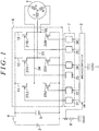
- FIG. 1 is a circuit diagram illustrating an electric power converter 1 according to an embodiment of the invention.
- the electric power converter 1 is a three-phase inverter circuit and supplies electric power to a three-phase motor 2.
- the electric power converter 1 includes a direct-current (DC) power source 3, a power supply switch 4, a smoothing capacitor 5, an inverter circuit unit 6 (an inverter unit), a driver circuit unit 7 (a driver unit), a shunt resistor 8 (a short circuit detector), and a microcomputer 9 (a controller).
- DC direct-current
- the electric power converter 1 includes a direct-current (DC) power source 3, a power supply switch 4, a smoothing capacitor 5, an inverter circuit unit 6 (an inverter unit), a driver circuit unit 7 (a driver unit), a shunt resistor 8 (a short circuit detector), and a microcomputer 9 (a controller).
- DC direct-current
- the smoothing capacitor 5 is connected in series with the DC power source 3 via the power supply switch 4.
- the inverter circuit unit 6 is connected in parallel with the smoothing capacitor 5.
- the inverter circuit unit 6 includes a U-phase arm circuit 11, a V-phase arm circuit 12, and a W-phase arm circuit 13.
- the U-phase arm circuit 11, the V-phase arm circuit 12, and the W-phase arm circuit 13 respectively correspond to a U-phase winding, a V-phase winding, and a W-phase winding of the three-phase motor 2.
- the U-phase arm circuit 11, the V-phase arm circuit 12, and the W-phase arm circuit 13 are connected in parallel with the smoothing capacitor 5.
- the U-phase arm circuit 11 includes a series circuit of a high-side first high electron mobility transistor (HEMT) 21U and a low-side second HEMT 22U.
- the first HEMT 21U forms an upper arm.
- the second HEMT 22U forms a lower arm.
- the first HEMT 21U and the second HEMT 22U are normally-off devices.
- the V-phase arm circuit 12 includes a series circuit of a high-side first HEMT 21V and a low-side second HEMT 22V
- the first HEMT 21V forms an upper arm.
- the second HEMT 22V forms a lower arm.
- the first HEMT 21V and the second HEMT 22V are normally-off devices.
- the W-phase arm circuit 13 includes a series circuit of a high-side first HEMT 21W and a low-side second HEMT 22W.
- the first HEMT 21W forms an upper arm.
- the second HEMT 22W forms a lower arm.
- the first HEMT 21W and the second HEMT 22W are normally-off devices.
- Each of the first HEMTs 21U, 21V, and 21W has a first gate electrode, a first source electrode, and a first drain electrode.
- Each of the second HEMTs 22U, 22V, and 22W has a second gate electrode, a second source electrode, and a second drain electrode.
- the U-phase arm circuit 11 is formed by connecting the first source electrode of the first HEMT 21U to the second drain electrode of the second HEMT 22U.
- the V-phase arm circuit 12 is formed by connecting the first source electrode of the first HEMT 21V to the second drain electrode of the second HEMT 22V.
- the W-phase arm circuit 13 is formed by connecting the first source electrode of the first HEMT 21W to the second drain electrode of the second HEMT 22W.
- Each of the first HEMTs 21U, 21V, and 21W has a first threshold voltage Vth1.
- the first HEMTs 21U, 21V, and 21W switch from an off state to an on state when both the following conditions are satisfied: a first drain voltage VD1 is greater than or equal to a first source voltage VS1 (i.e., VD1 ⁇ VS1); and a first gate-source voltage VGS1 between the first gate electrode and the first source electrode is greater than the first threshold voltage Vth1 (i.e., VGS1 > Vth1).
- the first HEMTs 21U, 21V, and 21W switch from the on state back to the off state when the first gate-source voltage VGS1 becomes less than or equal to the first threshold voltage Vth1 (i.e., VGS1 ⁇ Vth1). Further, the first HEMTs 21U, 21V, and 21W switch from the off state to the on state when both the following conditions are satisfied: the first drain voltage VD1 is less than the first source voltage VS1 (i.e., VD1 ⁇ VS1); and a first gate-drain voltage VGD1 between the first gate electrode and the first drain electrode is greater than the first threshold voltage Vth1 (i.e., VGD1 > Vth1).
- the first HEMTs 21U, 21V, and 21W switch from the on state back to the off state when the first gate-drain voltage VGD1 becomes less than or equal to the first threshold voltage Vth1 (i.e., VGD1 ⁇ Vth1).
- Each of the second HEMTs 22U, 22V, and 22W has a second threshold voltage Vth2.
- the second HEMTs 22U, 22V, and 22W switch from an off state to an on state when both the following conditions are satisfied: a second drain voltage VD2 is greater than or equal to a second source voltage VS2 (i.e., VD2 ⁇ VS2); and a second gate-source voltage VGS2 between the second gate electrode and the second source electrode is greater than the second threshold voltage Vth2 (i.e., VGS2 > Vth2).
- the second HEMTs 22U, 22V, and 22W switch from the on state back to the off state when the second gate-source voltage VGS2 becomes less than or equal to the second threshold voltage Vth2 (i.e., VGS2 ⁇ Vth2). Further, the second HEMTs 22U, 22V, and 22W switch from the off state to the on state when both the following conditions are satisfied: the second drain voltage VD2 is less than the second source voltage VS2 (i.e., VD2 ⁇ VS2); and a second gate-drain voltage VGD2 between the second gate electrode and the second drain electrode is greater than the second threshold voltage Vth2 (i.e., VGD2 > Vth2).
- the second HEMTs 22U, 22V, and 22W switch from the on state back to the off state when the second gate-drain voltage VGD2 becomes less than or equal to the second threshold voltage Vth2 (i.e., VGD2 ⁇ Vth2).
- the first HEMTs 21U, 21V, and 21W have two-dimensional electron gas (2DEG) channels and therefore have no freewheeling diodes.
- the first HEMTs 21U, 21V, and 21W are not connected to any freewheeling diodes.
- the second HEMTs 22U, 22V, and 22W have 2DEG channels and therefore have no freewheeling diodes.
- the second HEMTs 22U, 22V, and 22W are not connected to any freewheeling diodes.
- a U-phase wire 24 is connected to a U-phase connection node between the first HEMT 21U and the second HEMT 22U of the U-phase arm circuit 11.
- the U-phase wire 24 is also connected to the U-phase winding of the three-phase motor 2.
- a V-phase wire 25 is connected to a V-phase connection node between the first HEMT 21V and the second HEMT 22V of the V-phase arm circuit 12.
- the V-phase wire 25 is also connected to the V-phase winding of the three-phase motor 2.
- a W-phase wire 26 is connected to a W-phase connection node between the first HEMT 21W and the second HEMT 22W of the W-phase arm circuit 13.
- the W-phase wire 26 is connected to the W-phase winding of the three-phase motor 2.
- the driver circuit unit 7 includes a U-phase upper driver circuit unit 31, a U-phase lower driver circuit unit 32, a V-phase upper driver circuit unit 33, a V-phase lower driver circuit unit 34, a W-phase upper driver circuit unit 35, and a W-phase lower driver circuit unit 36.
- the U-phase upper driver circuit unit 31 is connected to the first HEMT 21U of the U-phase arm circuit 11.
- the U-phase upper driver circuit unit 31 generates an on-off signal to alternately turn on and off the first HEMT 21U and outputs the on-off signal to the first gate electrode of the first HEMT 21U.
- the U-phase lower driver circuit unit 32 is connected to the second HEMT 22U of the U-phase arm circuit 11.
- the U-phase lower driver circuit unit 32 generates an on-off signal to alternately turn on and off the second HEMT 22U and outputs the on-off signal to the second gate electrode of the second HEMT 22U.
- the V-phase upper driver circuit unit 33 is connected to the first HEMT 21V of the V-phase arm circuit 12.
- the V-phase upper driver circuit unit 33 generates an on-off signal to alternately turn on and off the first HEMT 21V and outputs the on-off signal to the first gate electrode of the first HEMT 21V.
- the V-phase lower driver circuit unit 34 is connected to the second HEMT 22V of the V-phase arm circuit 12.
- the V-phase lower driver circuit unit 34 generates an on-off signal to alternately turn on and off the second HEMT 22V and outputs the on-off signal to the second gate electrode of the second HEMT 22V
- the W-phase upper driver circuit unit 35 is connected to the first HEMT 21W of the W-phase arm circuit 13.
- the W-phase upper driver circuit unit 35 generates an on-off signal to alternately turn on and off the first HEMT 21W and outputs the on-off signal to the first gate electrode of the first HEMT 21W.
- the W-phase lower driver circuit unit 36 is connected to the second HEMT 22W of the W-phase arm circuit 13.
- the W-phase lower driver circuit unit 36 generates an on-off signal to alternately turn on and off the second HEMT 22W and outputs the on-off signal to the second gate electrode of the second HEMT 22W.
- the shunt resistor 8 is interposed between the inverter circuit unit 6 and ground. When electric current flows from the inverter circuit unit 6 to the ground through the shunt resistor 8, a terminal voltage VR appears across terminals of the shunt resistor 8.
- the microcomputer 9 is connected to the driver circuit unit 7 and the shunt resistor 8.
- the microcomputer 9 generates on-off commands to individually turn on and off the first HEMTs 21U, 21V, and 21W and outputs each of the on-off commands to a corresponding one of the U-phase upper driver circuit unit 31, the V-phase upper driver circuit unit 33, and the W-phase upper driver circuit unit 35.
- the microcomputer 9 generates on-off commands to individually turn on and off the second HEMTs 22U, 22V, and 22W and outputs each of the on-off commands to a corresponding one of the U-phase lower driver circuit unit 32, the V-phase lower driver circuit unit 34, and the W-phase lower driver circuit unit 36. Further, the microcomputer 9 determines, on the basis of the terminal voltage VR of the shunt resistor 8, whether a short circuit occurs in the inverter circuit unit 6.
- the U-phase upper driver circuit unit 31, the V-phase upper driver circuit unit 33, and the W-phase upper driver circuit unit 35 generate on-off signals in accordance with the respective on-off commands from the microcomputer 9, and respectively output the on-off signals to the first HEMTs 21U, 21V, and 21W.
- the first HEMTs 21U, 21V, and 21W are turned on and off in a predetermined switching pattern.
- the U-phase lower driver circuit unit 32, the V-phase lower driver circuit unit 34, and the W-phase lower driver circuit unit 36 generate on-off signals in accordance with the respective on-off commands from the microcomputer 9, and respectively output the on-off signals to the second HEMTs 22U, 22V, and 22W.
- the second HEMTs 22U, 22V, and 22W are turned on and off in a predetermined switching pattern.
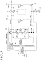
- FIG. 2 is a circuit diagram of the U-phase upper driver circuit unit 31 illustrated in FIG. 1 .
- the V-phase upper driver circuit unit 33 and the W-phase upper driver circuit unit 35 are almost identical in structure and circuit operation to the U-phase upper driver circuit unit 31.
- FIG. 2 omits the W-phase arm circuit 13 and other components that are not referred to in the description of the U-phase upper driver circuit unit 31.
- the U-phase upper driver circuit unit 31 is connected to the microcomputer 9, the first gate electrode of the first HEMT 21U, the first drain electrode of the first HEMT 21U, and the first source electrode of the first HEMT 21U.
- the U-phase upper driver circuit unit 31 includes a first output circuit unit 41, a first auxiliary power source 42, a first switch circuit unit 43 (a switch unit), and a first diode 44.
- the first output circuit unit 41 generates and outputs an on signal to the first gate electrode of the first HEMT 21U in response to an on command from the microcomputer 9.
- the first output circuit unit 41 generates and outputs an off signal to the first gate electrode of the first HEMT 21U in response to an off command from the microcomputer 9.
- the first output circuit unit 41 includes a series circuit of a p-type first upper metal insulator semiconductor field effect transistor (MISFET) 45 and an n-type first lower MISFET 46. More specifically, in the first output circuit unit 41, the p-type first upper MISFET 45 and the n-type first lower MISFET 46 are complementarily connected to form a first complementary metal insulator semiconductor (CMIS) circuit.
- the first CMIS circuit forms a NOT gate as an example of a logic circuit.
- the first upper MISFET 45 includes a first upper gate electrode, a first upper source electrode, and a first upper drain electrode.
- the first lower MISFET 46 includes a first lower gate electrode, a first lower source electrode, and a first lower drain electrode.
- the first output circuit unit 41 is formed by connecting the first upper drain electrode of the first upper MISFET 45 to the first lower drain electrode of the first lower MISFET 46.
- the first upper gate electrode of the first upper MISFET 45 and the first lower gate electrode of the first lower MISFET 46 are connected together to the microcomputer 9.
- a first connection node 47 between the first upper MISFET 45 and the first lower MISFET 46 is connected to the first gate electrode of the first HEMT 21U.
- a first upper freewheeling diode 48 is connected in parallel with the first upper MISFET 45 and is oriented such that forward current through the first upper freewheeling diode 48 flows from the first upper drain electrode of the first upper MISFET 45 to the first upper source electrode of the first upper MISFET 45.
- a first lower freewheeling diode 49 is connected in parallel with the first lower MISFET 46 and is oriented such that forward current through the first lower freewheeling diode 49 flows from the first lower source electrode of the first lower MISFET 46 to the first lower drain electrode of the first lower MISFET 46.
- the first output circuit unit 41 receives the on command from the microcomputer 9, the first upper MISFET 45 switches to an on state, and the first lower MISFET 46 switches to an off state. In this case, the first upper MISFET 45 generates and outputs the on signal to the first gate electrode of the first HEMT 21U.
- the first output circuit unit 41 When the first output circuit unit 41 receives the off command from the microcomputer 9, the first upper MISFET 45 switches to an off state, and the first lower MISFET 46 switches to an on state. In this case, the first lower MISFET 46 generates and outputs the off signal to the first gate electrode of the first HEMT 21U.
- the first auxiliary power source 42 is connectable via the first switch circuit unit 43 to the first upper source electrode of the first upper MISFET 45.
- the first auxiliary power source 42 outputs a predetermined positive voltage with respect to a source voltage of the first HEMT 21U.
- the first switch circuit unit 43 is interposed between the first drain electrode of the first HEMT 21U, the first upper source electrode of the first upper MISFET 45, and the first auxiliary power source 42.
- the first switch circuit unit 43 is connected to the microcomputer 9. In accordance with a switch command from the microcomputer 9, the first switch circuit unit 43 switches between a first connection state and a second connection state so as to change a connection destination.
- the first switch circuit unit 43 connects the first upper source electrode of the first upper MISFET 45 to the first auxiliary power source 42.
- the first switch circuit unit 43 connects the first upper source electrode of the first upper MISFET 45 to the first drain electrode of the first HEMT 21U.
- the first switch circuit unit 43 is normally controlled to be in the first connection state, and switches from the first connection state to the second connection state upon reception of the switch command from the microcomputer 9.
- the first diode 44 is interposed between the first lower source electrode of the first lower MISFET 46 and the first source electrode of the first HEMT 21U, and is oriented such that forward current through the first diode 44 flows from the first lower source electrode of the first lower MISFET 46 to the first source electrode of the first HEMT 21U.
- the circuit operation of the U-phase upper driver circuit unit 31 is specifically described. The following description describes how the U-phase upper driver circuit unit 31 operates in the event of a short circuit in the first HEMT 21V of the V-phase arm circuit 12.
- a motor phase voltage VM oscillates between plus five volts (+5 V) and minus five volts (-5 V), and that a power supply voltage VE is 12 V
- the motor phase voltage VM is induced by rotation of the three-phase motor 2 and oscillates between positive and negative values.
- a first auxiliary power source voltage VSE1 of the first auxiliary power source 42 is 10 V
- the first threshold voltage Vth1 of the first HEMT 21U is 3 V
- a ground voltage VGND is 0 V.
- the first upper MISFET 45 switches to the off state, and the first lower MISFET 46 switches to the on state.
- electric current flows from the first HEMT 21U to the first diode 44 through the first lower MISFET 46.
- the first forward voltage Vf1 is about 0.6 V
- the first drain voltage VD1 is greater than or equal to the first source voltage VS1 (i.e., VD1 ⁇ VS1). More specifically, the first drain voltage VD1 is greater than the first source voltage VS1 (i.e., VD1 > VS1).
- the first gate-source voltage VGS1 is less than or equal to the first threshold voltage Vth1 of the first HEMT 21U (i.e., VGS1 ⁇ Vth1). More specifically, the first gate-source voltage VGS1 is less than the first threshold voltage Vth1 (i.e., VGS1 ⁇ Vth1). Therefore, the first HEMT 21U switches to the off state, so that electric current does not flow between the three-phase motor 2 and the inverter circuit unit 6.
- the motor phase voltage VM becomes -5 V
- the microcomputer 9 outputs the off command to the U-phase upper driver circuit unit 31
- the first gate voltage VG1 of the first HEMT 21U increases with the increase in the first source voltage VS1 and eventually reaches 17 V.
- the first drain voltage VD1 is less than the first source voltage VS1 (i.e., VD1 ⁇ VS1).
- the first gate-drain voltage VGD1 is greater than the first threshold voltage Vth1 of the first HEMT 21U (i.e., VGD1 > Vth1).
- the U-phase upper driver circuit unit 31 receives the off command from the microcomputer 9, the first HEMT 21U switches to the on state, so that electric current flows between the three-phase motor 2 and the inverter circuit unit 6.
- the U-phase upper driver circuit unit 31 performs the following control.
- shoot-through current IT flows into the shunt resistor 8 due to a short circuit in the first HEMT 21V
- the terminal voltage VR across the shunt resistor 8 increases.
- the terminal voltage VR is output to the microcomputer 9.
- the microcomputer 9 determines whether a short circuit occurs in any of the HEMTs (in this example, the first HEMT 21V). If determining that a short circuit occurs in any of the HEMTs (in this example, the first HEMT 21V), the microcomputer 9 outputs the off command to the U-phase upper driver circuit unit 31. Further, the microcomputer 9 outputs the switch command to the first switch circuit unit 43.
- the first upper MISFET 45 switches to the off state, and the first lower MISFET 46 switches to the on state. Further, the first switch circuit unit 43 switches from the first connection state to the second connection state. As such, the first drain electrode of the first HEMT 21U is connected to the first upper source electrode of the first upper MISFET 45.
- the motor phase voltage VM is +5 V
- electric current flows through the first diode 44. This causes the first forward voltage Vf1 across the first diode 44.
- the first forward voltage Vf1 is about 0.6 V.
- the first drain voltage VD1 is greater than or equal to the first source voltage VS1 (i.e., VD1 ⁇ VS1). More specifically, the first drain voltage VD1 is greater than the first source voltage VS1 (i.e., VD1 > VS1).
- the first gate-source voltage VGS1 is less than or equal to the first threshold voltage Vth1 of the first HEMT 21U (i.e., VGS1 ⁇ Vth1). More specifically, the first gate-source voltage VGS1 is less than the first threshold voltage Vth1 (i.e., VGS1 ⁇ Vth1). Therefore, the first HEMT 21U switches to the off state, so that electric current does not flow between the three-phase motor 2 and the inverter circuit unit 6.
- the motor phase voltage VM becomes -5 V
- electric current flows through a closed circuit including the first HEMT 21U, the first upper MISFET 45, and the first switch circuit unit 43. In this case, the first diode 44 blocks the flow of electric current from the three-phase motor 2 to the first lower source electrode of the first lower MISFET 46.
- a second forward voltage Vf2 appears across the first upper freewheeling diode 48.
- the second forward voltage Vf2 is about 0.6 V.
- the first drain voltage VD1 is less than or equal to the first source voltage VS1 (i.e., VD1 ⁇ VS1). More specifically, the first drain voltage VD1 is less than the first source voltage VS1 (i.e., VD1 ⁇ VS1).
- the first gate-drain voltage VGD1 is less than or equal to the first threshold voltage Vth1 of the first HEMT 21U (i.e., VGD1 ⁇ Vth1). More specifically, the first gate-drain voltage VGD1 is less than the first threshold voltage Vth1 (i.e., VGD1 ⁇ Vth1). Therefore, the first HEMT 21U switches to the off state, so that electric current does not flow between the three-phase motor 2 and the inverter circuit unit 6.
- a short circuit may occur in any of the HEMTs (in this example, the first HEMT 21V), when the first drain voltage VD1 of the first HEMT 21U that is not short-circuited is greater than or equal to the first source voltage VS1 (i.e., VD1 ⁇ VS1).
- the first gate-source voltage VGS1 is controlled to be less than or equal to the first threshold voltage Vth1 of the first HEMT 21U (i.e., VGS1 ⁇ Vth1).
- a short circuit may occur in any of the HEMTs (in this example, the first HEMT 21V), when the first drain voltage VD1 of the first HEMT 21U that is not short-circuited is less than the first source voltage VS1 (i.e., VD1 ⁇ VS1).
- the first gate-drain voltage VGD1 is controlled to be less than or equal to the first threshold voltage Vth1 of the first HEMT 21U (i.e., VGD1 ⁇ Vth1).
- the U-phase upper driver circuit unit 31 forces the first HEMT 21U to the off state, regardless of whether the motor phase voltage VM is positive or negative, thereby keeping the first HEMT 21U from switching to the on state.
- electric current does not flow between the first drain electrode and the first source electrode of the first HEMT 21U.
- electric current does not flow between the three-phase motor 2 and the inverter circuit unit 6.
- FIG. 3 is a circuit diagram of the U-phase lower driver circuit unit 32 illustrated in FIG. 1 .
- the V-phase lower driver circuit unit 34 and the W-phase lower driver circuit unit 36 are almost identical in structure and circuit operation to the U-phase lower driver circuit unit 32. For this reason, the structure and circuit operation of only the U-phase lower driver circuit unit 32 are described here.
- the description of the U-phase lower driver circuit unit 32 made below applies similarly to the V-phase lower driver circuit unit 34 and the W-phase lower driver circuit unit 36, and therefore the descriptions of the V-phase lower driver circuit unit 34 and the W-phase lower driver circuit unit 36 are omitted.
- FIG. 3 omits the W-phase arm circuit 13 and other components that are not referred to in the description of the U-phase lower driver circuit unit 32.
- the U-phase lower driver circuit unit 32 is connected to the microcomputer 9, the second gate electrode of the second HEMT 22U, the second drain electrode of the second HEMT 22U, and the second source electrode of the second HEMT 22U.
- the U-phase lower driver circuit unit 32 includes a second output circuit unit 51, a second auxiliary power source 52, a second switch circuit unit 53 (a switch unit), and a second diode 54.
- the second output circuit unit 51 generates and outputs an on signal to the second gate electrode of the second HEMT 22U in response to an on command from the microcomputer 9.
- the second output circuit unit 51 generates and outputs an off signal to the second gate electrode of the second HEMT 22U in response to an off command from the microcomputer 9.
- the second output circuit unit 51 includes a series circuit of a p-type second upper MISFET 55 and an n-type second lower MISFET 56.
- the second upper MISFET 55 and the second lower MISFET 56 are complementarily connected to form a second CMIS circuit.
- the second CMIS circuit forms a NOT gate as an example of a logic circuit.
- the second upper MISFET 55 includes a second upper gate electrode, a second upper source electrode, and a second upper drain electrode.
- the second lower MISFET 56 includes a second lower gate electrode, a second lower source electrode, and a second lower drain electrode.
- the second output circuit unit 51 is formed by connecting the second upper drain electrode of the second upper MISFET 55 to the second lower drain electrode of the second lower MISFET 56.
- the second upper gate electrode of the second upper MISFET 55 and the second lower gate electrode of the second lower MISFET 56 are connected together to the microcomputer 9.
- a second connection node 57 between the second upper MISFET 55 and the second lower MISFET 56 is connected to the second gate electrode of the second HEMT 22U.
- a second upper freewheeling diode 58 is connected in parallel with the second upper MISFET 55 and is oriented such that forward current through the second upper freewheeling diode 58 flows from the second upper drain electrode of the second upper MISFET 55 to the second upper source electrode of the second upper MISFET 55.
- a second lower freewheeling diode 59 is connected in parallel with the second lower MISFET 56 and is oriented such that forward current through the second lower freewheeling diode 59 flows from the second upper source electrode of the second lower MISFET 56 to the second lower drain electrode of the second lower MISFET 56.
- the second output circuit unit 51 When the second output circuit unit 51 receives the on command from the microcomputer 9, the second upper MISFET 55 switches to an on state, and the second lower MISFET 56 switches to an off state. In this case, the second upper MISFET 55 generates and outputs the on signal to the second gate electrode of the second HEMT 22U.
- the second output circuit unit 51 receives the off command from the microcomputer 9, the second upper MISFET 55 switches to an off state, and the second lower MISFET 56 switches to an on state. In this case, the second lower MISFET 56 generates and outputs the off signal to the second gate electrode of the second HEMT 22U.
- the second auxiliary power source 52 is connectable via the second switch circuit unit 53 to the second upper source electrode of the second upper MISFET 55.
- the second auxiliary power source 52 outputs a predetermined positive voltage with respect to a source voltage of the second HEMT 22U.
- the second switch circuit unit 53 is interposed between the second drain electrode of the second HEMT 22U, the second upper source electrode of the second upper MISFET 55, and the second auxiliary power source 52.
- the second switch circuit unit 53 is connected to the microcomputer 9.
- the second switch circuit unit 53 switches between a first connection state and a second connection state so as to change a connection destination.
- the second switch circuit unit 53 connects the second upper source electrode of the second upper MISFET 55 to the second auxiliary power source 52.
- the second switch circuit unit 53 connects the second upper source electrode of the second upper MISFET 55 to the second drain electrode of the second HEMT 22U.
- the second switch circuit unit 53 is normally controlled to be in the first connection state, and switches from the first connection state to the second connection state upon reception of the switch command from the microcomputer 9.
- the second diode 54 is interposed between the second lower source electrode of the second lower MISFET 56 and the second source electrode of the second HEMT 22U, and is oriented such that forward current through the second diode 54 flows from the second lower source electrode of the second lower MISFET 56 to the second source electrode of the second HEMT 22U.
- the second upper MISFET 55 switches to the off state
- the second lower MISFET 56 switches to the on state.
- electric current flows from the second HEMT 22U to the second diode 54 through the second lower MISFET 56.
- the third forward voltage Vf3 is about 0.6 V.
- the second drain voltage VD2 is greater than or equal to the second source voltage VS2 (i.e., VD2 ⁇ VS2). More specifically, the second drain voltage VD2 is greater than the second source voltage VS2 (i.e., VD2 > VS2).
- the second gate-source voltage VGS2 is less than or equal to the second threshold voltage Vth2 of the second HEMT 22U (i.e., VGS2 ⁇ Vth2). More specifically, the second gate-source voltage VGS2 is less than the second threshold voltage Vth2 (i.e., VGS2 ⁇ Vth2). Therefore, the second HEMT 22U switches to the off state, so that electric current does not flow between the three-phase motor 2 and the inverter circuit unit 6.
- the second drain voltage VD2 of the second HEMT 22U becomes -5 V.
- the second drain voltage VD2 is less than the second source voltage VS2 (i.e., VD2 ⁇ VS2).
- the second gate-drain voltage VGD2 is greater than the second threshold voltage Vth2 of the second HEMT 22U (i.e., VGD2 > Vth2).
- the U-phase lower driver circuit unit 32 receives the off command from the microcomputer 9, the second HEMT 22U switches to the on state, so that electric current flows between the three-phase motor 2 and the inverter circuit unit 6.
- the U-phase lower driver circuit unit 32 performs the following control.
- the shoot-through current IT flows into the shunt resistor 8 due to a short circuit in the second HEMT 22U
- the terminal voltage VR across the shunt resistor 8 increases.
- the terminal voltage VR is output to the microcomputer 9.
- the microcomputer 9 If determining, on the basis of the terminal voltage VR, that a short circuit occurs in any of the HEMTs (in this example, the second HEMT 22V), the microcomputer 9 outputs the off command to the U-phase lower driver circuit unit 32. Further, the microcomputer 9 outputs the switch command to the second switch circuit unit 53. Thus, the second upper MISFET 55 switches to the off state, and the second lower MISFET 56 switches to the on state. Further, the second switch circuit unit 53 switches from the first connection state to the second connection state. As such, the second upper source electrode of the second upper MISFET 55 is connected to the second drain electrode of the second HEMT 22U.
- the second drain voltage VD2 is greater than or equal to the second source voltage VS2 (i.e., VD2 ⁇ VS2). More specifically, the second drain voltage VD2 is greater than the second source voltage VS2 (i.e., VD2 > VS2).
- the second gate-source voltage VGS2 is less than or equal to the second threshold voltage Vth2 of the second HEMT 22U (i.e., VGS2 ⁇ Vth2). More specifically, the second gate-source voltage VGS2 is less than the second threshold voltage Vth2 (i.e., VGS2 ⁇ Vth2). Therefore, the second HEMT 22U switches to the off state, so that electric current does not flow between the three-phase motor 2 and the inverter circuit unit 6.
- the second gate-drain voltage VGD2 is less than or equal to the second threshold voltage Vth2 of the second HEMT 22U (i.e., VGD2 ⁇ Vth2). More specifically, the second gate-drain voltage VGD2 is less than the second threshold voltage Vth2 (i.e., VGD2 ⁇ Vth2). Therefore, the second HEMT 22U switches to the off state, so that electric current does not flow between the three-phase motor 2 and the inverter circuit unit 6.
- a short circuit may occur in any of the HEMTs (in this example, the second HEMT 22V), when the second drain voltage VD2 of the second HEMT 22U that is not short-circuited is greater than or equal to the second source voltage VS2 (i.e., VD2 ⁇ VS2).
- the second gate-source voltage VGS2 of the second HEMT 22U is controlled to be less than or equal to the second threshold voltage Vth2 of the second HEMT 22U (i.e., VGS2 ⁇ Vth2).
- a short circuit may occur in any of the HEMTs (in this example, the second HEMT 22V), when the second drain voltage VD2 of the second HEMT 22U that is not short-circuited is less than the second source voltage VS2 (i.e., VD2 ⁇ VS2).
- the second gate-drain voltage VGD2 of the second HEMT 22U is controlled to be less than or equal to the second threshold voltage Vth2 of the second HEMT 22U (i.e., VGD2 ⁇ Vth2).
- the U-phase lower driver circuit unit 32 forces the second HEMT 22U to the off state, regardless of whether the motor phase voltage VM is positive or negative, thereby keeping the second HEMT 22U from switching to the on state.
- electric current does not flow between the second drain electrode and the second source electrode of the second HEMT 22U. As a result, electric current does not flow between the three-phase motor 2 and the inverter circuit unit 6.
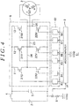
- FIG. 4 is a circuit diagram illustrating an electric power converter 61 according to a reference example of the invention. Like elements between the electric power converters 1 and 61 are represented by like reference symbols and are not described again here.
- a first HEMT 21U, a second HEMT 22U, a first HEMT 21V, a second HEMT 22V, a first HEMT 21W, and a second HEMT 22W are either normally-off devices or normally-on devices.
- the following description assumes that the first HEMT 21U, the second HEMT 22U, the first HEMT 21V, the second HEMT 22V, the first HEMT 21W, and the second HEMT 22W are all normally-on devices.
- Each of the first HEMTs 21U, 21V, and 21W has a first threshold voltage Vth11.
- the first HEMTs 21U, 21V, and 21W switch from an on state to an off state, when both the following conditions are satisfied: a first drain voltage VD1 is greater than or equal to a first source voltage VS1 (i.e., VD1 ⁇ VS1); and a first gate-source voltage VGS1 between a first gate electrode and a first source electrode is less than or equal to the first threshold voltage Vth11 (i.e., VGS1 ⁇ Vth11).
- the first HEMTs 21U, 21V, and 21W switch from the off state back to the on state, when the first gate-source voltage VGS1 exceeds the first threshold voltage Vth11 (i.e., VGS1 > Vth11). Further, the first HEMTs 21U, 21V, and 21W switch from the on state to the off state, when both the following conditions are satisfied: the first drain voltage VD1 is less than the first source voltage VS1 (i.e., VD1 ⁇ VS1); and a first gate-drain voltage VGD1 between the first gate electrode and a first drain electrode is less than or equal to the first threshold voltage Vth11 (i.e., VGD1 ⁇ Vth11).
- the first HEMTs 21U, 21V, and 21W switch from the off state back to the on state, when the first gate-drain voltage VGD1 exceeds the first threshold voltage Vth11 (i.e., VGD1 > Vth11).
- Each of the second HEMTs 22U, 22V, and 22W has a second threshold voltage Vth12.
- the second HEMTs 22U, 22V, and 22W switch from an on state to an off state, when both the following conditions are satisfied: a second drain voltage VD2 is greater than or equal to a second source voltage VS2 (i.e., VD2 ⁇ VS2); and a second gate-source voltage VGS2 between a second gate electrode and a second source electrode is less than or equal to the second threshold voltage Vth12 (i.e., VGS2 ⁇ Vth12).
- the second HEMTs 22U, 22V, and 22W switch from the off state back to the on state, when the second gate-source voltage VGS2 exceeds the second threshold voltage Vth12 (i.e., VGS2 > Vth12). Further, the second HEMTs 22U, 22V, and 22W switch from the on state to the off state, when both the following conditions are satisfied: the second drain voltage VD2 is less than the second source voltage VS2 (i.e., VD2 ⁇ VS2); and a second gate-drain voltage VGD2 between the second gate electrode and a second drain electrode is less than or equal to the second threshold voltage Vth12 (i.e., VGD2 ⁇ Vth12).
- the electric power converter 61 includes a driver circuit 62 instead of the driver circuit unit 7.
- the driver circuit 62 includes a U-phase upper driver circuit unit 63, a U-phase lower driver circuit unit 64, a V-phase upper driver circuit unit 65, a V-phase lower driver circuit unit 66, a W-phase upper driver circuit unit 67, and a W-phase lower driver circuit unit 68.
- FIG. 5 is a circuit diagram illustrating the U-phase upper driver circuit unit 63 and the U-phase lower driver circuit unit 64 for the U-phase arm circuit 11 illustrated in FIG. 4 .
- the V-phase upper driver circuit unit 65 and the W-phase upper driver circuit unit 67 are almost identical in structure and circuit operation to the U-phase upper driver circuit unit 63.
- the description of the U-phase upper driver circuit unit 63 made below applies similarly to the V-phase upper driver circuit unit 65 and the W-phase upper driver circuit unit 67, and therefore the descriptions of the V-phase upper driver circuit unit 65 and the W-phase upper driver circuit unit 67 are omitted.
- the V-phase lower driver circuit unit 66 and the W-phase lower driver circuit unit 68 are almost identical in structure and circuit operation to the U-phase lower driver circuit unit 64.
- the description of the U-phase lower driver circuit unit 64 made below applies similarly to the V-phase lower driver circuit unit 66 and the W-phase lower driver circuit unit 68, and therefore the descriptions of the V-phase lower driver circuit unit 66 and the W-phase lower driver circuit unit 68 are omitted.
- the structure and circuit operation of the U-phase upper driver circuit unit 63 are described first, and then the structure and circuit operation of the U-phase lower driver circuit unit 64 are described.
- the U-phase upper driver circuit unit 63 includes the first output circuit unit 41, a first forced-off-signal output unit 69, and a first switch circuit unit 70.
- the first output circuit unit 41 is formed by connecting the first upper drain electrode of the first upper MISFET 45 to the first lower drain electrode of the first lower MISFET 46.
- the first connection node 47 between the first upper MISFET 45 and the first lower MISFET 46 is connectable via the first switch circuit unit 70 to the first gate electrode of the first HEMT 21U.
- the first forced-off-signal output unit 69 is also connectable via the first switch circuit unit 70 to the first gate electrode of the first HEMT 21U.
- the first forced-off-signal output unit 69 outputs, to the first gate electrode of the first HEMT 21U via the first switch circuit unit 70, a forced-off-signal that forces the first HEMT 21U to the off state.
- the first forced-off-signal output unit 69 includes a first power source 71 and outputs, as the forced-off-signal, a predetermined first voltage VN1 to the first gate electrode of the first HEMT 21U.
- the first voltage VN1 is defined with respect to a ground voltage VGND.
- the first voltage VN1 is set less than or equal to the value of the following expression: Vth11 -
- the first switch circuit unit 70 is interposed between the first HEMT 21U, the first output circuit unit 41, and the first forced-off-signal output unit 69.
- the first switch circuit unit 70 is connected to a microcomputer 9. In accordance with a switch command from the microcomputer 9, the first switch circuit unit 70 switches between a first connection state and a second connection state so as to change a connection destination.
- the first switch circuit unit 70 connects the first gate electrode of the first HEMT 21U to the first output circuit unit 41.
- the first switch circuit unit 70 connects the first gate electrode of the first HEMT 21U to the first forced-off-signal output unit 69.
- the first switch circuit unit 70 is normally controlled to be in the first connection state, and switches from the first connection state to the second connection state upon reception of the switch command from the microcomputer 9.
- the circuit operation of the U-phase upper driver circuit unit 63 is specifically described.
- the following description describes how the U-phase upper driver circuit unit 63 operates in the event of a short circuit in the first HEMT 21V of the V-phase arm circuit 12.
- shoot-through current IT flows into a shunt resistor 8 due to a short circuit in the first HEMT 21V
- a terminal voltage VR across the shunt resistor 8 increases.
- the terminal voltage VR is output to the microcomputer 9.
- the microcomputer 9 determines whether a short circuit occurs in any of the HEMTs (in this example, the first HEMT 21V). If determining that a short circuit occurs in any of the HEMTs (in this example, the first HEMT 21V), the microcomputer 9 outputs the switch command to the first switch circuit unit 70.
- the first forced-off-signal output unit 69 is connected to the first gate electrode of the first HEMT 21U so that the forced-off-signal is output to the first gate electrode of the first HEMT 21U.
- the motor phase voltage VM oscillates between +5 V and -5 V, and that the power supply voltage VE is 12 V.
- the first threshold voltage Vth11 of the first HEMT 21U is -3 V, and the ground voltage VGND is 0 V.
- the first gate voltage VG1 of the first HEMT 21U ( ⁇ Vth11 -
- the first drain voltage VD1 is less than or equal to the first source voltage VS1 (i.e., VD1 ⁇ VS1). More specifically, the first drain voltage VD1 is less than the first source voltage VS1 (i.e., VD1 ⁇ VS1).
- the first gate-drain voltage VGD1 is less than or equal to the first threshold voltage Vth11 of the first HEMT 21U (i.e., VGD1 ⁇ Vth11).
- the first gate-drain voltage VGD1 is less than the first threshold voltage Vth11 of the first HEMT 21U (i.e., VGD1 ⁇ Vth11). Therefore, the first HEMT 21U switches to the off state, so that electric current does not flow between the three-phase motor 2 and the inverter circuit unit 6.
- the first gate voltage VG1 of the first HEMT 21U ( ⁇ Vth11 -
- the first drain voltage VD1 is greater than or equal to the first source voltage VS1 (i.e., VD1 ⁇ VS1). More specifically, the first drain voltage VD1 is greater than the first source voltage VS1 (i.e., VD1 > VS1).
- the first gate-source voltage VGS1 is less than or equal to the first threshold voltage Vth11 of the first HEMT 21U (i.e., VGS1 ⁇ Vth11). Therefore, the first HEMT 21U switches to the off state, so that electric current does not flow between the three-phase motor 2 and the inverter circuit unit 6.
- the first gate-source voltage VGS1 becomes less than the first threshold voltage Vth11 (i.e., VGS1 ⁇ Vth11) by setting the first voltage VN1 to be less than the value of the following expression: Vth11 -
- the first forced-off-signal output unit 69 outputs the forced-off-signal to the first HEMT 21U that is not short-circuited.
- the first drain voltage VD1 of the first HEMT 21U is less than the first source voltage VS1 of the first HEMT 21U (i.e., VD1 ⁇ VS1).
- the forced-off-signal causes the first gate-drain voltage VGD1 of the first HEMT 21U to be less than or equal to the first threshold voltage Vth11 of the first HEMT 21U (i.e., VGD1 ⁇ Vth11).
- the forced-off-signal when the forced-off-signal is output, the first drain voltage VD1 of the first HEMT 21U is greater than or equal to the first source voltage VS1 of the first HEMT 21U (VD1 ⁇ VS1).
- the forced-off-signal causes the first gate-source voltage VGS1 of the first HEMT 21U to be less than or equal to the first threshold voltage Vth11 of the first HEMT 21U (i.e., VGS1 ⁇ Vth11).
- the first voltage VN1 from the first power source 71 serves as the forced-off-signal.
- the first voltage VN1 is set less than or equal to the value of the following expression: Vth11 -
- the U-phase upper driver circuit unit 63 keeps the first HEMT 21U from switching to the on state, regardless of whether the motor phase voltage VM is positive or negative.
- electric current does not flow between the first drain electrode and the first source electrode of the first HEMT 21U.
- electric current does not flow between the three-phase motor 2 and the inverter circuit unit 6.
- the U-phase lower driver circuit unit 64 includes the second output circuit unit 51, a second forced-off-signal output unit 72, and a second switch circuit unit 73.
- the second output circuit unit 51 is formed by connecting the second upper drain electrode of the second upper MISFET 55 to the second lower drain electrode of the second lower MISFET 56.
- the second connection node 57 between the second upper MISFET 55 and the second lower MISFET 56 is connectable via the second switch circuit unit 73 to the second gate electrode of the second HEMT 22U.
- the second forced-off-signal output unit 72 is also connectable via the second switch circuit unit 73 to the second gate electrode of the second HEMT 22U.
- the second forced-off-signal output unit 72 outputs, to the second gate electrode of the second HEMT 22U via the second switch circuit unit 73, a forced-off-signal that forces the second HEMT 22U to the off state.
- the second forced-off-signal output unit 72 includes a second power source 74 and outputs, as the forced-off-signal, a predetermined second voltage VN2 to the second gate electrode of the second HEMT 22U.
- the second voltage VN2 is defined with respect to the ground voltage VGND.
- the second voltage VN2 is set less than or equal to the value of the following expression: Vth12 -
- the second switch circuit unit 73 is interposed between the second HEMT 22U, the second output circuit unit 51, and the second forced-off-signal output unit 72.
- the second switch circuit unit 73 is connected to the microcomputer 9. In accordance with a switch command from the microcomputer 9, the second switch circuit unit 73 switches between a first connection state and a second connection state so as to change a connection destination.
- the second switch circuit unit 73 connects the second gate electrode of the second HEMT 22U to the second output circuit unit 51. In the second connection state, the second switch circuit unit 73 connects the second gate electrode of the second HEMT 22U to the second forced-off-signal output unit 72. According to the reference example, the second switch circuit unit 73 is normally controlled to be in the first connection state, and switches from the first connection state to the second connection state upon reception of the switch command from the microcomputer 9.
- the circuit operation of the U-phase lower driver circuit unit 64 is specifically described.
- the following description describes how the U-phase lower driver circuit unit 64 operates in the event of a short circuit in the second HEMT 22V of the V-phase arm circuit 12.
- the terminal voltage VR across the shunt resistor 8 increases.
- the terminal voltage VR is output to the microcomputer 9.
- the microcomputer 9 determines whether a short circuit occurs in any of the HEMTs (in this example, the second HEMT 22V). If determining that a short circuit occurs in any of the HEMTs (in this example, the second HEMT 22V), the microcomputer 9 outputs the switch command to the second switch circuit unit 73.
- the second forced-off-signal output unit 72 is connected to the second gate electrode of the second HEMT 22U so that the forced-off-signal is output to the second gate electrode of the second HEMT 22U.
- the motor phase voltage VM oscillates between +5 V and -5 V, and that the power supply voltage VE is 12 V.
- the second threshold voltage Vth12 of the second HEMT 22U is -3 V, and the ground voltage VGND is 0 V.
- ) is less than or equal to -8 V.
- the second drain voltage VD2 is greater than or equal to the second source voltage VS2 (VD2 ⁇ VS2). More specifically, the second drain voltage VD2 is greater than the second source voltage VS2 (i.e., VD2 > VS2).
- the second gate-source voltage VGS2 is less than or equal to the second threshold voltage Vth12 of the second HEMT 22U (i.e., VGS2 ⁇ Vth12). More specifically, the second gate-source voltage VGS2 is less than the second threshold voltage Vth12 (i.e., VGS2 ⁇ Vth12). Therefore, the second HEMT 22U switches to the off state, so that electric current does not flow between the three-phase motor 2 and the inverter circuit unit 6.
- the second drain voltage VD2 of the second HEMT 22U becomes -5 V.
- the second gate voltage VG2 of the second HEMT 22U ( ⁇ Vth12 -
- the second drain voltage VD2 is less than or equal to the second source voltage VS2 (i.e., VD2 ⁇ VS2).
- the second gate-drain voltage VGD2 of the second HEMT 22U is less than or equal to -3 V.
- the second gate-drain voltage VGD2 is less than or equal to the second threshold voltage Vth12 of the second HEMT 22U (i.e., VGD2 ⁇ Vth12). Therefore, the second HEMT 22U switches to the off state, so that electric current does not flow between the three-phase motor 2 and the inverter circuit unit 6.
- the second gate-drain voltage VGD2 becomes less than the second threshold value Vth12 (i.e., VGD2 ⁇ Vth12) by setting the second voltage VN2 to be less than the value of the following expression: Vth12 -
- the second forced-off-signal output unit 72 outputs the forced-off-signal to the second HEMT 22U that is not short-circuited.
- the second drain voltage VD2 of the second HEMT 22U is greater than or equal to the second source voltage VS2 of the second HEMT 22U (i.e., VD2 ⁇ VS2).
- the forced-off-signal causes the second gate-source voltage VGS2 of the second HEMT 22U to be less than or equal to the second threshold value Vth12 of the second HEMT 22U (i.e., VGS2 ⁇ Vth12).
- the second drain voltage VD2 of the second HEMT 22U is less than the second source voltage VS2 of the second HEMT 22U (i.e., VD2 ⁇ VS2).
- the forced-off-signal causes the second gate-drain voltage VGD2 of the second HEMT 22U to be less than or equal to the second threshold value Vth12 of the second HEMT 22U (i.e., VGD2 ⁇ Vth12).
- the second voltage VN2 from the second power source 74 serves as the forced-off-signal.
- the second voltage VN2 is set less than or equal to the value of the following expression: Vth12 -
- the U-phase lower driver circuit unit 64 keeps the second HEMT 22U from switching to the on state, regardless of whether the motor phase voltage VM is positive or negative.
- electric current does not flow between the second drain electrode and the second source electrode of the second HEMT 22U.
- electric current does not flow between the three-phase motor 2 and the inverter circuit unit 6.
- the first CMIS circuit may be a single-chip circuit or a two-chip circuit. That is, the p-type first upper MISFET 45 and the n-type first lower MISFET 46 may be combined in one chip, or may be formed on separate chips.
- the second CMIS circuit may be a single-chip circuit or a two-chip circuit. That is, the p-type second upper MISFET 55 and the n-type second lower MISFET 56 may be combined in one chip, or may be formed on separate chips.
- the electric power converters 1, 16 may be built in a vehicle electric power steering system, as inverter circuits for supplying electric power to a three-phase motor. Other modifications are possible within the scope of the invention.
Landscapes
- Engineering & Computer Science (AREA)
- Power Engineering (AREA)
- Chemical & Material Sciences (AREA)
- Combustion & Propulsion (AREA)
- Transportation (AREA)
- Mechanical Engineering (AREA)
- Control Of Ac Motors In General (AREA)
- Inverter Devices (AREA)
Abstract
Description
- The invention relates to an electric power converter.
- Japanese Patent Application Publication No.
2014-045576 JP 2014-045576 A - Each of the U-phase arm circuit, the V-phase arm circuit, and the W-phase arm circuit includes a high-side metal oxide semiconductor field effect transistor (MOSFET) and a low-side MOSFET. The motor relay is interposed between the motor and the inverter unit to interrupt electrical connection between the motor and the inverter unit in the event a problem occurs with the motor or the inverter unit. The motor relay includes a U-phase motor relay, a V-phase motor relay, and a W-phase motor relay respectively corresponding to the U-phase winding, the V-phase winding, and the W-phase winding of the motor.
- The U-phase motor relay is interposed between the U-phase arm circuit and the U-phase winding of the motor. The V-phase motor relay is interposed between the V-phase arm circuit and the V-phase winding of the motor. The W-phase motor relay is interposed between the W-phase arm circuit and the W-phase winding of the motor.
- In the electric power converter disclosed in
JP 2014-045576 A - A purpose of the invention is to provide an electric power converter that allows cost and size reduction.
- An electric power converter including the following: an inverter unit configured to convert direct current power, from a direct current source, to alternating current to drive a motor and including multiple high electron mobility transistors (HEMTs) that form multiple arm circuits; multiple driver units, each connected to and configured to turn on and off a corresponding one of the HEMTs; a short circuit detector configured to detect a short circuit in the HEMTs; and a controller connected to the driver units and the short circuit detector, and configured to control the driver units. Each of the driver units includes an output unit, an auxiliary power source, a switch unit, and a diode. The output unit includes a series circuit of first and second switching elements with drain electrodes connected together. The output unit responds to on and off commands from the controller by respectively outputting on and off signals to a gate electrode of the corresponding HEMT from a connection node between the first and second switching elements to turn on and off the corresponding HEMT. The auxiliary power source outputs a predetermined positive voltage. The switch unit switches between a first connection state and a second connection state. In the first connection state, the switch unit connects a source electrode of the first switching element to the auxiliary power source. In the second connection state, the switch unit connects the source electrode of the first switching element to a drain electrode of the corresponding HEMT. The diode is interposed between a source electrode of the second switching element and a source electrode of the corresponding HEMT, and is oriented such that forward current through the diode flows from the source electrode of the second switching element to the source electrode of the corresponding HEMT. The controller switches the switch unit from the first connection state to the second connection state and outputs the off command to each of the driver units when determining, on the basis of an output of the short circuit detector, that the short circuit occurs in any of the HEMTs.
- The foregoing and further features and advantages of the invention will become apparent from the following description of example embodiments with reference to the accompanying drawings, wherein like numerals are used to represent like elements and wherein:
-
FIG. 1 is a circuit diagram illustrating an electric power converter according to an embodiment of the invention; -
FIG. 2 is a circuit diagram illustrating an upper driver circuit unit for a U-phase arm circuit illustrated inFIG. 1 ; -
FIG. 3 is a circuit diagram illustrating a lower driver circuit unit for the U-phase arm circuit illustrated inFIG. 1 ; -
FIG. 4 is a circuit diagram illustrating an electric power converter according to a reference example of the invention; and -
FIG. 5 is a circuit diagram illustrating an upper driver circuit unit and a lower driver circuit unit for a U-phase arm circuit illustrated inFIG. 4 . - Embodiments of the invention are described in detail below with reference to the drawings.
FIG. 1 is a circuit diagram illustrating an electric power converter 1 according to an embodiment of the invention. According to the embodiment, the electric power converter 1 is a three-phase inverter circuit and supplies electric power to a three-phase motor 2. Referring toFIG. 1 , the electric power converter 1 includes a direct-current (DC)power source 3, apower supply switch 4, a smoothing capacitor 5, an inverter circuit unit 6 (an inverter unit), a driver circuit unit 7 (a driver unit), a shunt resistor 8 (a short circuit detector), and a microcomputer 9 (a controller). - The smoothing capacitor 5 is connected in series with the
DC power source 3 via thepower supply switch 4. Theinverter circuit unit 6 is connected in parallel with the smoothing capacitor 5. Theinverter circuit unit 6 includes aU-phase arm circuit 11, a V-phase arm circuit 12, and a W-phase arm circuit 13. TheU-phase arm circuit 11, the V-phase arm circuit 12, and the W-phase arm circuit 13 respectively correspond to a U-phase winding, a V-phase winding, and a W-phase winding of the three-phase motor 2. TheU-phase arm circuit 11, the V-phase arm circuit 12, and the W-phase arm circuit 13 are connected in parallel with the smoothing capacitor 5. - The
U-phase arm circuit 11 includes a series circuit of a high-side first high electron mobility transistor (HEMT) 21U and a low-side second HEMT 22U. The first HEMT 21U forms an upper arm. The second HEMT 22U forms a lower arm. The first HEMT 21U and the second HEMT 22U are normally-off devices. - The V-
phase arm circuit 12 includes a series circuit of a high-sidefirst HEMT 21V and a low-side second HEMT 22V The first HEMT 21V forms an upper arm. The second HEMT 22V forms a lower arm. The first HEMT 21V and the second HEMT 22V are normally-off devices. - The W-
phase arm circuit 13 includes a series circuit of a high-side first HEMT 21W and a low-side second HEMT 22W. The first HEMT 21W forms an upper arm. The second HEMT 22W forms a lower arm. The first HEMT 21W and the second HEMT 22W are normally-off devices. - Each of the
first HEMTs second HEMTs U-phase arm circuit 11 is formed by connecting the first source electrode of thefirst HEMT 21U to the second drain electrode of thesecond HEMT 22U. The V-phase arm circuit 12 is formed by connecting the first source electrode of thefirst HEMT 21V to the second drain electrode of thesecond HEMT 22V. The W-phase arm circuit 13 is formed by connecting the first source electrode of thefirst HEMT 21W to the second drain electrode of thesecond HEMT 22W. - Each of the
first HEMTs first HEMTs - Then, the
first HEMTs first HEMTs - Then, the
first HEMTs second HEMTs second HEMTs - Then, the
second HEMTs second HEMTs - Then, the
second HEMTs first HEMTs first HEMTs - Likewise, the
second HEMTs second HEMTs U-phase wire 24 is connected to a U-phase connection node between thefirst HEMT 21U and thesecond HEMT 22U of theU-phase arm circuit 11. TheU-phase wire 24 is also connected to the U-phase winding of the three-phase motor 2. - A V-
phase wire 25 is connected to a V-phase connection node between thefirst HEMT 21V and thesecond HEMT 22V of the V-phase arm circuit 12. The V-phase wire 25 is also connected to the V-phase winding of the three-phase motor 2. A W-phase wire 26 is connected to a W-phase connection node between thefirst HEMT 21W and thesecond HEMT 22W of the W-phase arm circuit 13. The W-phase wire 26 is connected to the W-phase winding of the three-phase motor 2. - The
driver circuit unit 7 includes a U-phase upperdriver circuit unit 31, a U-phase lowerdriver circuit unit 32, a V-phase upperdriver circuit unit 33, a V-phase lowerdriver circuit unit 34, a W-phase upper driver circuit unit 35, and a W-phase lower driver circuit unit 36. The U-phase upperdriver circuit unit 31 is connected to thefirst HEMT 21U of theU-phase arm circuit 11. The U-phase upperdriver circuit unit 31 generates an on-off signal to alternately turn on and off thefirst HEMT 21U and outputs the on-off signal to the first gate electrode of thefirst HEMT 21U. - The U-phase lower
driver circuit unit 32 is connected to thesecond HEMT 22U of theU-phase arm circuit 11. The U-phase lowerdriver circuit unit 32 generates an on-off signal to alternately turn on and off thesecond HEMT 22U and outputs the on-off signal to the second gate electrode of thesecond HEMT 22U. The V-phase upperdriver circuit unit 33 is connected to thefirst HEMT 21V of the V-phase arm circuit 12. The V-phase upperdriver circuit unit 33 generates an on-off signal to alternately turn on and off thefirst HEMT 21V and outputs the on-off signal to the first gate electrode of thefirst HEMT 21V. - The V-phase lower
driver circuit unit 34 is connected to thesecond HEMT 22V of the V-phase arm circuit 12. The V-phase lowerdriver circuit unit 34 generates an on-off signal to alternately turn on and off thesecond HEMT 22V and outputs the on-off signal to the second gate electrode of thesecond HEMT 22V The W-phase upper driver circuit unit 35 is connected to thefirst HEMT 21W of the W-phase arm circuit 13. The W-phase upper driver circuit unit 35 generates an on-off signal to alternately turn on and off thefirst HEMT 21W and outputs the on-off signal to the first gate electrode of thefirst HEMT 21W. - The W-phase lower driver circuit unit 36 is connected to the
second HEMT 22W of the W-phase arm circuit 13. The W-phase lower driver circuit unit 36 generates an on-off signal to alternately turn on and off thesecond HEMT 22W and outputs the on-off signal to the second gate electrode of thesecond HEMT 22W. Theshunt resistor 8 is interposed between theinverter circuit unit 6 and ground. When electric current flows from theinverter circuit unit 6 to the ground through theshunt resistor 8, a terminal voltage VR appears across terminals of theshunt resistor 8. - The
microcomputer 9 is connected to thedriver circuit unit 7 and theshunt resistor 8. Themicrocomputer 9 generates on-off commands to individually turn on and off thefirst HEMTs driver circuit unit 31, the V-phase upperdriver circuit unit 33, and the W-phase upper driver circuit unit 35. Themicrocomputer 9 generates on-off commands to individually turn on and off thesecond HEMTs driver circuit unit 32, the V-phase lowerdriver circuit unit 34, and the W-phase lower driver circuit unit 36. Further, themicrocomputer 9 determines, on the basis of the terminal voltage VR of theshunt resistor 8, whether a short circuit occurs in theinverter circuit unit 6. - The U-phase upper
driver circuit unit 31, the V-phase upperdriver circuit unit 33, and the W-phase upper driver circuit unit 35 generate on-off signals in accordance with the respective on-off commands from themicrocomputer 9, and respectively output the on-off signals to thefirst HEMTs first HEMTs driver circuit unit 32, the V-phase lowerdriver circuit unit 34, and the W-phase lower driver circuit unit 36 generate on-off signals in accordance with the respective on-off commands from themicrocomputer 9, and respectively output the on-off signals to thesecond HEMTs second HEMTs - As such, the
first HEMTs second HEMTs DC power source 3, to alternating current (AC) to sinusoidally drive the three-phase motor 2.FIG. 2 is a circuit diagram of the U-phase upperdriver circuit unit 31 illustrated inFIG. 1 . The V-phase upperdriver circuit unit 33 and the W-phase upper driver circuit unit 35 are almost identical in structure and circuit operation to the U-phase upperdriver circuit unit 31. - For this reason, the structure and circuit operation of only the U-phase upper
driver circuit unit 31 are described here as an example. The description of the U-phase upperdriver circuit unit 31 made below applies similarly to the V-phase upperdriver circuit unit 33 and the W-phase upper driver circuit unit 35, and therefore the descriptions of the V-phase upperdriver circuit unit 33 and the W-phase upper driver circuit unit 35 are omitted. For the sake of brevity,FIG. 2 omits the W-phase arm circuit 13 and other components that are not referred to in the description of the U-phase upperdriver circuit unit 31. The U-phase upperdriver circuit unit 31 is connected to themicrocomputer 9, the first gate electrode of thefirst HEMT 21U, the first drain electrode of thefirst HEMT 21U, and the first source electrode of thefirst HEMT 21U. - The U-phase upper
driver circuit unit 31 includes a firstoutput circuit unit 41, a firstauxiliary power source 42, a first switch circuit unit 43 (a switch unit), and afirst diode 44. The firstoutput circuit unit 41 generates and outputs an on signal to the first gate electrode of thefirst HEMT 21U in response to an on command from themicrocomputer 9. The firstoutput circuit unit 41 generates and outputs an off signal to the first gate electrode of thefirst HEMT 21U in response to an off command from themicrocomputer 9. - Specifically, the first
output circuit unit 41 includes a series circuit of a p-type first upper metal insulator semiconductor field effect transistor (MISFET) 45 and an n-type firstlower MISFET 46. More specifically, in the firstoutput circuit unit 41, the p-type firstupper MISFET 45 and the n-type firstlower MISFET 46 are complementarily connected to form a first complementary metal insulator semiconductor (CMIS) circuit. The first CMIS circuit forms a NOT gate as an example of a logic circuit. - The first
upper MISFET 45 includes a first upper gate electrode, a first upper source electrode, and a first upper drain electrode. The firstlower MISFET 46 includes a first lower gate electrode, a first lower source electrode, and a first lower drain electrode. The firstoutput circuit unit 41 is formed by connecting the first upper drain electrode of the firstupper MISFET 45 to the first lower drain electrode of the firstlower MISFET 46. - The first upper gate electrode of the first
upper MISFET 45 and the first lower gate electrode of the firstlower MISFET 46 are connected together to themicrocomputer 9. Afirst connection node 47 between the firstupper MISFET 45 and the firstlower MISFET 46 is connected to the first gate electrode of thefirst HEMT 21U. A first upper freewheelingdiode 48 is connected in parallel with the firstupper MISFET 45 and is oriented such that forward current through the first upper freewheelingdiode 48 flows from the first upper drain electrode of the firstupper MISFET 45 to the first upper source electrode of the firstupper MISFET 45. - A first lower freewheeling
diode 49 is connected in parallel with the firstlower MISFET 46 and is oriented such that forward current through the first lower freewheelingdiode 49 flows from the first lower source electrode of the firstlower MISFET 46 to the first lower drain electrode of the firstlower MISFET 46. When the firstoutput circuit unit 41 receives the on command from themicrocomputer 9, the firstupper MISFET 45 switches to an on state, and the firstlower MISFET 46 switches to an off state. In this case, the firstupper MISFET 45 generates and outputs the on signal to the first gate electrode of thefirst HEMT 21U. - When the first
output circuit unit 41 receives the off command from themicrocomputer 9, the firstupper MISFET 45 switches to an off state, and the firstlower MISFET 46 switches to an on state. In this case, the firstlower MISFET 46 generates and outputs the off signal to the first gate electrode of thefirst HEMT 21U. The firstauxiliary power source 42 is connectable via the firstswitch circuit unit 43 to the first upper source electrode of the firstupper MISFET 45. The firstauxiliary power source 42 outputs a predetermined positive voltage with respect to a source voltage of thefirst HEMT 21U. - The first
switch circuit unit 43 is interposed between the first drain electrode of thefirst HEMT 21U, the first upper source electrode of the firstupper MISFET 45, and the firstauxiliary power source 42. The firstswitch circuit unit 43 is connected to themicrocomputer 9. In accordance with a switch command from themicrocomputer 9, the firstswitch circuit unit 43 switches between a first connection state and a second connection state so as to change a connection destination. - In the first connection state, the first
switch circuit unit 43 connects the first upper source electrode of the firstupper MISFET 45 to the firstauxiliary power source 42. In the second connection state, the firstswitch circuit unit 43 connects the first upper source electrode of the firstupper MISFET 45 to the first drain electrode of thefirst HEMT 21U. According to the embodiment, the firstswitch circuit unit 43 is normally controlled to be in the first connection state, and switches from the first connection state to the second connection state upon reception of the switch command from themicrocomputer 9. - The
first diode 44 is interposed between the first lower source electrode of the firstlower MISFET 46 and the first source electrode of thefirst HEMT 21U, and is oriented such that forward current through thefirst diode 44 flows from the first lower source electrode of the firstlower MISFET 46 to the first source electrode of thefirst HEMT 21U. Next, the circuit operation of the U-phase upperdriver circuit unit 31 is specifically described. The following description describes how the U-phase upperdriver circuit unit 31 operates in the event of a short circuit in thefirst HEMT 21V of the V-phase arm circuit 12. - The following description assumes that a motor phase voltage VM oscillates between plus five volts (+5 V) and minus five volts (-5 V), and that a power supply voltage VE is 12 V The motor phase voltage VM is induced by rotation of the three-
phase motor 2 and oscillates between positive and negative values. A first auxiliary power source voltage VSE1 of the firstauxiliary power source 42 is 10 V, the first threshold voltage Vth1 of thefirst HEMT 21U is 3 V, and a ground voltage VGND is 0 V. - These voltage values are merely examples used to describe the circuit operation of the U-phase upper
driver circuit unit 31, and are not intended to limit voltages associated with the circuits to any specific values. First, a description is made about how the U-phase upperdriver circuit unit 31 operates if themicrocomputer 9 does not output the switch command to the firstswitch circuit unit 43 in the event of a short circuit in thefirst HEMT 21V The firstauxiliary power source 42 is connected to the first upper source electrode of the firstupper MISFET 45. - When the
microcomputer 9 outputs the off command to the U-phase upperdriver circuit unit 31, the firstupper MISFET 45 switches to the off state, and the firstlower MISFET 46 switches to the on state. Thus, electric current flows from thefirst HEMT 21U to thefirst diode 44 through the firstlower MISFET 46. This causes a first forward voltage Vf1 across thefirst diode 44. The first forward voltage Vf1 is about 0.6 V - When the motor phase voltage VM is 5 V, the first drain voltage VD1 of the
first HEMT 21U (= VE) is 12 V. The first source voltage VS1 of thefirst HEMT 21U (= VE - VM) is 7 V A first gate voltage VG1 of thefirst HEMT 21U (= VS1 + Vf1) is 7.6 V. Thus, the first drain voltage VD1 is greater than or equal to the first source voltage VS1 (i.e., VD1 ≥ VS1). More specifically, the first drain voltage VD1 is greater than the first source voltage VS1 (i.e., VD1 > VS1). The first gate-source voltage VGS1 of thefirst HEMT 21U (= VG1 - VS1) is 0.6 V. - Thus, the first gate-source voltage VGS1 is less than or equal to the first threshold voltage Vth1 of the
first HEMT 21U (i.e., VGS1 ≤ Vth1). More specifically, the first gate-source voltage VGS1 is less than the first threshold voltage Vth1 (i.e., VGS1 < Vth1). Therefore, thefirst HEMT 21U switches to the off state, so that electric current does not flow between the three-phase motor 2 and theinverter circuit unit 6. On the other hand, when the motor phase voltage VM becomes -5 V, while themicrocomputer 9 outputs the off command to the U-phase upperdriver circuit unit 31, the first drain voltage VD1 of thefirst HEMT 21U (= VE) becomes 12 V. Thus, the first source voltage VS1 of thefirst HEMT 21U (= VE - VM) becomes 17 V. - The first gate voltage VG1 of the
first HEMT 21U increases with the increase in the first source voltage VS1 and eventually reaches 17 V. The first drain voltage VD1 is less than the first source voltage VS1 (i.e., VD1 < VS1). The first gate-drain voltage VGD1 of thefirst HEMT 21U (= VG1 - VD1) is 5 V. Thus, the first gate-drain voltage VGD1 is greater than the first threshold voltage Vth1 of thefirst HEMT 21U (i.e., VGD1 > Vth1). In this case, although the U-phase upperdriver circuit unit 31 receives the off command from themicrocomputer 9, thefirst HEMT 21U switches to the on state, so that electric current flows between the three-phase motor 2 and theinverter circuit unit 6. - In the electric power converter 1, in order to interrupt the current flow between the three-
phase motor 2 and theinverter circuit unit 6, the U-phase upperdriver circuit unit 31 performs the following control. When shoot-through current IT flows into theshunt resistor 8 due to a short circuit in thefirst HEMT 21V, the terminal voltage VR across theshunt resistor 8 increases. The terminal voltage VR is output to themicrocomputer 9. - On the basis of the terminal voltage VR, the
microcomputer 9 determines whether a short circuit occurs in any of the HEMTs (in this example, thefirst HEMT 21V). If determining that a short circuit occurs in any of the HEMTs (in this example, thefirst HEMT 21V), themicrocomputer 9 outputs the off command to the U-phase upperdriver circuit unit 31. Further, themicrocomputer 9 outputs the switch command to the firstswitch circuit unit 43. - Thus, the first
upper MISFET 45 switches to the off state, and the firstlower MISFET 46 switches to the on state. Further, the firstswitch circuit unit 43 switches from the first connection state to the second connection state. As such, the first drain electrode of thefirst HEMT 21U is connected to the first upper source electrode of the firstupper MISFET 45. When the motor phase voltage VM is +5 V, electric current flows through thefirst diode 44. This causes the first forward voltage Vf1 across thefirst diode 44. The first forward voltage Vf1 is about 0.6 V. - At this time, the first drain voltage VD1 of the
first HEMT 21U (= VE) is 12 V. The first source voltage VS1 of thefirst HEMT 21U (= VE - VM) is 7 V. The first gate voltage VG1 of thefirst HEMT 21U (= VS1 + Vf1) is 7.6 V. Thus, the first drain voltage VD1 is greater than or equal to the first source voltage VS1 (i.e., VD1 ≥ VS1). More specifically, the first drain voltage VD1 is greater than the first source voltage VS1 (i.e., VD1 > VS1). The first gate-source voltage VGS1 of thefirst HEMT 21U (= VG1 - VS1) is 0.6 V. - Thus, the first gate-source voltage VGS1 is less than or equal to the first threshold voltage Vth1 of the
first HEMT 21U (i.e., VGS1 ≤ Vth1). More specifically, the first gate-source voltage VGS1 is less than the first threshold voltage Vth1 (i.e., VGS1 < Vth1). Therefore, thefirst HEMT 21U switches to the off state, so that electric current does not flow between the three-phase motor 2 and theinverter circuit unit 6. On the other hand, when the motor phase voltage VM becomes -5 V, electric current flows through a closed circuit including thefirst HEMT 21U, the firstupper MISFET 45, and the firstswitch circuit unit 43. In this case, thefirst diode 44 blocks the flow of electric current from the three-phase motor 2 to the first lower source electrode of the firstlower MISFET 46. - At this time, a second forward voltage Vf2 appears across the first upper freewheeling
diode 48. The second forward voltage Vf2 is about 0.6 V. Thus, the first drain voltage VD1 of the firstupper MISFET 45, i.e., the first gate voltage VG1 of thefirst HEMT 21U is clamped to a value (= VE + Vf2) that is the sum of the power supply voltage VE (= VD1) and the second forward voltage Vf2. At this time, the first drain voltage VD1 of thefirst HEMT 21U (= VE) is 12 V. The first source voltage VS1 of thefirst HEMT 21U (= VE - VM) is 17 V. The first gate voltage VG1 (= VE + Vf2) is 12.6 V. - Thus, the first drain voltage VD1 is less than or equal to the first source voltage VS1 (i.e., VD1 ≤ VS1). More specifically, the first drain voltage VD1 is less than the first source voltage VS1 (i.e., VD1 < VS1). The first gate-drain voltage VGD1 of the
first HEMT 21U (= VG1 - VD1) becomes 0.6 V. Thus, the first gate-drain voltage VGD1 is less than or equal to the first threshold voltage Vth1 of thefirst HEMT 21U (i.e., VGD1 ≤ Vth1). More specifically, the first gate-drain voltage VGD1 is less than the first threshold voltage Vth1 (i.e., VGD1 < Vth1). Therefore, thefirst HEMT 21U switches to the off state, so that electric current does not flow between the three-phase motor 2 and theinverter circuit unit 6. - As described above, a short circuit may occur in any of the HEMTs (in this example, the
first HEMT 21V), when the first drain voltage VD1 of thefirst HEMT 21U that is not short-circuited is greater than or equal to the first source voltage VS1 (i.e., VD1 ≥ VS1). According to the U-phase upperdriver circuit unit 31, if such a short circuit occurs, the first gate-source voltage VGS1 is controlled to be less than or equal to the first threshold voltage Vth1 of thefirst HEMT 21U (i.e., VGS1 ≤ Vth1). - Further, a short circuit may occur in any of the HEMTs (in this example, the
first HEMT 21V), when the first drain voltage VD1 of thefirst HEMT 21U that is not short-circuited is less than the first source voltage VS1 (i.e., VD1 < VS1). According to the U-phase upperdriver circuit unit 31, if such a short circuit occurs, the first gate-drain voltage VGD1 is controlled to be less than or equal to the first threshold voltage Vth1 of thefirst HEMT 21U (i.e., VGD1 ≤ Vth1). - As such, when a short circuit occurs in any of the HEMTs (in this example, the
first HEMT 21V), the U-phase upperdriver circuit unit 31 forces thefirst HEMT 21U to the off state, regardless of whether the motor phase voltage VM is positive or negative, thereby keeping thefirst HEMT 21U from switching to the on state. Thus, when a short circuit occurs in any of the HEMTs (in this example, thefirst HEMT 21V), electric current does not flow between the first drain electrode and the first source electrode of thefirst HEMT 21U. As a result, electric current does not flow between the three-phase motor 2 and theinverter circuit unit 6. -
FIG. 3 is a circuit diagram of the U-phase lowerdriver circuit unit 32 illustrated inFIG. 1 . The V-phase lowerdriver circuit unit 34 and the W-phase lower driver circuit unit 36 are almost identical in structure and circuit operation to the U-phase lowerdriver circuit unit 32. For this reason, the structure and circuit operation of only the U-phase lowerdriver circuit unit 32 are described here. The description of the U-phase lowerdriver circuit unit 32 made below applies similarly to the V-phase lowerdriver circuit unit 34 and the W-phase lower driver circuit unit 36, and therefore the descriptions of the V-phase lowerdriver circuit unit 34 and the W-phase lower driver circuit unit 36 are omitted. For the sake of brevity,FIG. 3 omits the W-phase arm circuit 13 and other components that are not referred to in the description of the U-phase lowerdriver circuit unit 32. - The U-phase lower
driver circuit unit 32 is connected to themicrocomputer 9, the second gate electrode of thesecond HEMT 22U, the second drain electrode of thesecond HEMT 22U, and the second source electrode of thesecond HEMT 22U. The U-phase lowerdriver circuit unit 32 includes a secondoutput circuit unit 51, a secondauxiliary power source 52, a second switch circuit unit 53 (a switch unit), and asecond diode 54. - The second
output circuit unit 51 generates and outputs an on signal to the second gate electrode of thesecond HEMT 22U in response to an on command from themicrocomputer 9. The secondoutput circuit unit 51 generates and outputs an off signal to the second gate electrode of thesecond HEMT 22U in response to an off command from themicrocomputer 9. Specifically, the secondoutput circuit unit 51 includes a series circuit of a p-type secondupper MISFET 55 and an n-type secondlower MISFET 56. - More specifically, in the second
output circuit unit 51, the secondupper MISFET 55 and the secondlower MISFET 56 are complementarily connected to form a second CMIS circuit. The second CMIS circuit forms a NOT gate as an example of a logic circuit. The secondupper MISFET 55 includes a second upper gate electrode, a second upper source electrode, and a second upper drain electrode. The secondlower MISFET 56 includes a second lower gate electrode, a second lower source electrode, and a second lower drain electrode. - The second
output circuit unit 51 is formed by connecting the second upper drain electrode of the secondupper MISFET 55 to the second lower drain electrode of the secondlower MISFET 56. The second upper gate electrode of the secondupper MISFET 55 and the second lower gate electrode of the secondlower MISFET 56 are connected together to themicrocomputer 9. Asecond connection node 57 between the secondupper MISFET 55 and the secondlower MISFET 56 is connected to the second gate electrode of thesecond HEMT 22U. - A second upper freewheeling
diode 58 is connected in parallel with the secondupper MISFET 55 and is oriented such that forward current through the second upper freewheelingdiode 58 flows from the second upper drain electrode of the secondupper MISFET 55 to the second upper source electrode of the secondupper MISFET 55. A second lower freewheelingdiode 59 is connected in parallel with the secondlower MISFET 56 and is oriented such that forward current through the second lower freewheelingdiode 59 flows from the second upper source electrode of the secondlower MISFET 56 to the second lower drain electrode of the secondlower MISFET 56. - When the second
output circuit unit 51 receives the on command from themicrocomputer 9, the secondupper MISFET 55 switches to an on state, and the secondlower MISFET 56 switches to an off state. In this case, the secondupper MISFET 55 generates and outputs the on signal to the second gate electrode of thesecond HEMT 22U. When the secondoutput circuit unit 51 receives the off command from themicrocomputer 9, the secondupper MISFET 55 switches to an off state, and the secondlower MISFET 56 switches to an on state. In this case, the secondlower MISFET 56 generates and outputs the off signal to the second gate electrode of thesecond HEMT 22U. - The second
auxiliary power source 52 is connectable via the secondswitch circuit unit 53 to the second upper source electrode of the secondupper MISFET 55. The secondauxiliary power source 52 outputs a predetermined positive voltage with respect to a source voltage of thesecond HEMT 22U. The secondswitch circuit unit 53 is interposed between the second drain electrode of thesecond HEMT 22U, the second upper source electrode of the secondupper MISFET 55, and the secondauxiliary power source 52. The secondswitch circuit unit 53 is connected to themicrocomputer 9. - In accordance with a switch command from the
microcomputer 9, the secondswitch circuit unit 53 switches between a first connection state and a second connection state so as to change a connection destination. In the first connection state, the secondswitch circuit unit 53 connects the second upper source electrode of the secondupper MISFET 55 to the secondauxiliary power source 52. In the second connection state, the secondswitch circuit unit 53 connects the second upper source electrode of the secondupper MISFET 55 to the second drain electrode of thesecond HEMT 22U. - According to the embodiment, the second
switch circuit unit 53 is normally controlled to be in the first connection state, and switches from the first connection state to the second connection state upon reception of the switch command from themicrocomputer 9. Thesecond diode 54 is interposed between the second lower source electrode of the secondlower MISFET 56 and the second source electrode of thesecond HEMT 22U, and is oriented such that forward current through thesecond diode 54 flows from the second lower source electrode of the secondlower MISFET 56 to the second source electrode of thesecond HEMT 22U. - Next, the circuit operation of the U-phase lower
driver circuit unit 32 is specifically described. The following description describes how the U-phase lowerdriver circuit unit 32 operates in the event of a short circuit in thesecond HEMT 22V of the V-phase arm circuit 12. As in the case of the description of the U-phase upperdriver circuit unit 31, the following description assumes that the motor phase voltage VM oscillates between +5 V and -5 V, and that the power supply voltage VE is 12 V. A second auxiliary power source voltage VSE2 of the secondauxiliary power source 52 is 10 V, the second threshold voltage Vth2 of thesecond HEMT 22U is 3 V, and the ground voltage VGND is 0 V. - These voltage values are merely examples used to describe the circuit operation of the U-phase lower
driver circuit unit 32, and are not intended to limit voltages associated with the circuits to any specific values. First, a description is made about how the U-phase lowerdriver circuit unit 32 operates if themicrocomputer 9 does not output the switch command to the secondswitch circuit unit 53 in the event of a short circuit in thesecond HEMT 22V. The secondauxiliary power source 52 is connected to the second upper source electrode of the secondupper MISFET 55. - When the
microcomputer 9 outputs the off command to the U-phase lowerdriver circuit unit 32, the secondupper MISFET 55 switches to the off state, and the secondlower MISFET 56 switches to the on state. Thus, electric current flows from thesecond HEMT 22U to thesecond diode 54 through the secondlower MISFET 56. This causes a third forward voltage Vf3 across thesecond diode 54. The third forward voltage Vf3 is about 0.6 V. - When the motor phase voltage VM is 5 V, the second drain voltage VD2 of the
second HEMT 22U (= VM) is 5 V. The second source voltage VS2 of thesecond HEMT 22U (= VGND) is 0 V. A second gate voltage VG2 of thesecond HEMT 22U (= VGND + Vf3) is 0.6 V. Thus, the second drain voltage VD2 is greater than or equal to the second source voltage VS2 (i.e., VD2 ≥ VS2). More specifically, the second drain voltage VD2 is greater than the second source voltage VS2 (i.e., VD2 > VS2). The second gate-source voltage VGS2 of thesecond HEMT 22U (= VG2 - VS2) is 0.6 V. - Thus, the second gate-source voltage VGS2 is less than or equal to the second threshold voltage Vth2 of the
second HEMT 22U (i.e., VGS2 ≤ Vth2). More specifically, the second gate-source voltage VGS2 is less than the second threshold voltage Vth2 (i.e., VGS2 < Vth2). Therefore, thesecond HEMT 22U switches to the off state, so that electric current does not flow between the three-phase motor 2 and theinverter circuit unit 6. On the other hand, when the motor phase voltage VM becomes -5 V, while themicrocomputer 9 outputs the off command to the U-phase lowerdriver circuit unit 32, the second drain voltage VD2 of thesecond HEMT 22U (= VE) becomes -5 V. The second source voltage VS2 of thesecond HEMT 22U (= VGND) is 0 V. The second gate voltage VG2 of thesecond HEMT 22U (= VGND + Vf3) is 0.6 V. - The second drain voltage VD2 is less than the second source voltage VS2 (i.e., VD2 < VS2). The second gate-drain voltage VGD2 of the
second HEMT 22U (= VG2 - VD2) is 5.6 V. Thus, the second gate-drain voltage VGD2 is greater than the second threshold voltage Vth2 of thesecond HEMT 22U (i.e., VGD2 > Vth2). In this case, although the U-phase lowerdriver circuit unit 32 receives the off command from themicrocomputer 9, thesecond HEMT 22U switches to the on state, so that electric current flows between the three-phase motor 2 and theinverter circuit unit 6. - In the electric power converter 1, in order to interrupt the current flow between the three-
phase motor 2 and theinverter circuit unit 6, the U-phase lowerdriver circuit unit 32 performs the following control. When the shoot-through current IT flows into theshunt resistor 8 due to a short circuit in thesecond HEMT 22U, the terminal voltage VR across theshunt resistor 8 increases. The terminal voltage VR is output to themicrocomputer 9. - If determining, on the basis of the terminal voltage VR, that a short circuit occurs in any of the HEMTs (in this example, the
second HEMT 22V), themicrocomputer 9 outputs the off command to the U-phase lowerdriver circuit unit 32. Further, themicrocomputer 9 outputs the switch command to the secondswitch circuit unit 53. Thus, the secondupper MISFET 55 switches to the off state, and the secondlower MISFET 56 switches to the on state. Further, the secondswitch circuit unit 53 switches from the first connection state to the second connection state. As such, the second upper source electrode of the secondupper MISFET 55 is connected to the second drain electrode of thesecond HEMT 22U. - When the motor phase voltage VM is +5 V, electric current flows through the
second diode 54. This causes the third forward voltage Vf3 across thesecond diode 54. The third forward voltage Vf3 is about 0.6 V. At this time, the second drain voltage VD2 of thesecond HEMT 22U (= VM) is +5 V. The second source voltage VS2 of thesecond HEMT 22U (= VGND) is 0 V. The second gate voltage VG2 of thesecond HEMT 22U (= VGND + Vf3) is 0.6 V. - Thus, the second drain voltage VD2 is greater than or equal to the second source voltage VS2 (i.e., VD2 ≥ VS2). More specifically, the second drain voltage VD2 is greater than the second source voltage VS2 (i.e., VD2 > VS2). The second gate-source voltage VGS2 of the
second HEMT 22U (= VG2 - VS2) is 0.6 V. Thus, the second gate-source voltage VGS2 is less than or equal to the second threshold voltage Vth2 of thesecond HEMT 22U (i.e., VGS2 ≤ Vth2). More specifically, the second gate-source voltage VGS2 is less than the second threshold voltage Vth2 (i.e., VGS2 < Vth2). Therefore, thesecond HEMT 22U switches to the off state, so that electric current does not flow between the three-phase motor 2 and theinverter circuit unit 6. - On the other hand, when the motor phase voltage VM becomes -5 V, electric current flows through a closed circuit including the
second HEMT 22U, the secondupper MISFET 55, and the secondswitch circuit unit 53. In this case, thesecond diode 54 blocks the flow of electric current from the three-phase motor 2 to the second lower source electrode of the secondlower MISFET 56. At this time, a fourth forward voltage Vf4 appears across the second upper freewheelingdiode 58. The fourth forward voltage Vf4 is about 0.6 V. Thus, the second gate voltage VG2 of thesecond HEMT 22U is clamped to a value (= VD2 + Vf4) that is the sum of the second drain voltage VD2 and the fourth forward voltage Vf4. - At this time, the second drain voltage VD2 of the
second HEMT 22U (= VM) is -5 V. The second source voltage VS2 of thesecond HEMT 22U (= VGND) is 0 V. The second gate voltage VG2 (= VD2 + Vf4) is -4.4 V. The second gate-drain voltage VGD2 of thesecond HEMT 22U (= VG2 - VD2) is 0.6 V. - Thus, the second gate-drain voltage VGD2 is less than or equal to the second threshold voltage Vth2 of the
second HEMT 22U (i.e., VGD2 ≤ Vth2). More specifically, the second gate-drain voltage VGD2 is less than the second threshold voltage Vth2 (i.e., VGD2 < Vth2). Therefore, thesecond HEMT 22U switches to the off state, so that electric current does not flow between the three-phase motor 2 and theinverter circuit unit 6. - As described above, a short circuit may occur in any of the HEMTs (in this example, the
second HEMT 22V), when the second drain voltage VD2 of thesecond HEMT 22U that is not short-circuited is greater than or equal to the second source voltage VS2 (i.e., VD2 ≥ VS2). According to the U-phase lowerdriver circuit unit 32, if such a short circuit occurs, the second gate-source voltage VGS2 of thesecond HEMT 22U is controlled to be less than or equal to the second threshold voltage Vth2 of thesecond HEMT 22U (i.e., VGS2 ≤ Vth2). - Further, a short circuit may occur in any of the HEMTs (in this example, the
second HEMT 22V), when the second drain voltage VD2 of thesecond HEMT 22U that is not short-circuited is less than the second source voltage VS2 (i.e., VD2 < VS2). According to the U-phase lowerdriver circuit unit 32, if such a short circuit occurs, the second gate-drain voltage VGD2 of thesecond HEMT 22U is controlled to be less than or equal to the second threshold voltage Vth2 of thesecond HEMT 22U (i.e., VGD2 ≤ Vth2). - As such, when a short circuit occurs in any of the HEMTs (in this example, the
second HEMT 22V), the U-phase lowerdriver circuit unit 32 forces thesecond HEMT 22U to the off state, regardless of whether the motor phase voltage VM is positive or negative, thereby keeping thesecond HEMT 22U from switching to the on state. Thus, when a short circuit occurs in any of the HEMTs (in this example, thesecond HEMT 22V), electric current does not flow between the second drain electrode and the second source electrode of thesecond HEMT 22U. As a result, electric current does not flow between the three-phase motor 2 and theinverter circuit unit 6. - In conclusion, according to the electric power converter 1, there is no need to interpose motor relays between the three-
phase motor 2 and theinverter circuit unit 6. This leads to a reduction in the number of components of the electric power converter 1, thus making it possible to reduce the cost and size of the electric power converter 1.FIG. 4 is a circuit diagram illustrating anelectric power converter 61 according to a reference example of the invention. Like elements between theelectric power converters 1 and 61 are represented by like reference symbols and are not described again here. - According to the
electric power converter 61, afirst HEMT 21U, asecond HEMT 22U, afirst HEMT 21V, asecond HEMT 22V, afirst HEMT 21W, and asecond HEMT 22W are either normally-off devices or normally-on devices. The following description assumes that thefirst HEMT 21U, thesecond HEMT 22U, thefirst HEMT 21V, thesecond HEMT 22V, thefirst HEMT 21W, and thesecond HEMT 22W are all normally-on devices. - Each of the
first HEMTs first HEMTs - Then, the
first HEMTs first HEMTs - Then, the
first HEMTs second HEMTs second HEMTs - Then, the
second HEMTs second HEMTs - Then, the
second HEMTs electric power converter 61 includes adriver circuit 62 instead of thedriver circuit unit 7. Thedriver circuit 62 includes a U-phase upperdriver circuit unit 63, a U-phase lowerdriver circuit unit 64, a V-phase upperdriver circuit unit 65, a V-phase lowerdriver circuit unit 66, a W-phase upperdriver circuit unit 67, and a W-phase lower driver circuit unit 68. -
FIG. 5 is a circuit diagram illustrating the U-phase upperdriver circuit unit 63 and the U-phase lowerdriver circuit unit 64 for theU-phase arm circuit 11 illustrated inFIG. 4 . The V-phase upperdriver circuit unit 65 and the W-phase upperdriver circuit unit 67 are almost identical in structure and circuit operation to the U-phase upperdriver circuit unit 63. - For this reason, the description of the U-phase upper
driver circuit unit 63 made below applies similarly to the V-phase upperdriver circuit unit 65 and the W-phase upperdriver circuit unit 67, and therefore the descriptions of the V-phase upperdriver circuit unit 65 and the W-phase upperdriver circuit unit 67 are omitted. The V-phase lowerdriver circuit unit 66 and the W-phase lower driver circuit unit 68 are almost identical in structure and circuit operation to the U-phase lowerdriver circuit unit 64. - For this reason, the description of the U-phase lower
driver circuit unit 64 made below applies similarly to the V-phase lowerdriver circuit unit 66 and the W-phase lower driver circuit unit 68, and therefore the descriptions of the V-phase lowerdriver circuit unit 66 and the W-phase lower driver circuit unit 68 are omitted. The structure and circuit operation of the U-phase upperdriver circuit unit 63 are described first, and then the structure and circuit operation of the U-phase lowerdriver circuit unit 64 are described. - Referring to
FIG. 5 , the U-phase upperdriver circuit unit 63 includes the firstoutput circuit unit 41, a first forced-off-signal output unit 69, and a firstswitch circuit unit 70. As in the electric power converter 1, the firstoutput circuit unit 41 is formed by connecting the first upper drain electrode of the firstupper MISFET 45 to the first lower drain electrode of the firstlower MISFET 46. - The
first connection node 47 between the firstupper MISFET 45 and the firstlower MISFET 46 is connectable via the firstswitch circuit unit 70 to the first gate electrode of thefirst HEMT 21U. The first forced-off-signal output unit 69 is also connectable via the firstswitch circuit unit 70 to the first gate electrode of thefirst HEMT 21U. The first forced-off-signal output unit 69 outputs, to the first gate electrode of thefirst HEMT 21U via the firstswitch circuit unit 70, a forced-off-signal that forces thefirst HEMT 21U to the off state. - According to the reference example, the first forced-off-
signal output unit 69 includes afirst power source 71 and outputs, as the forced-off-signal, a predetermined first voltage VN1 to the first gate electrode of thefirst HEMT 21U. The first voltage VN1 is defined with respect to a ground voltage VGND. On the basis of the first threshold voltage Vth11 of thefirst HEMT 21U, the motor phase voltage VM, and the power supply voltage VE, the first voltage VN1 is set less than or equal to the value of the following expression: Vth11 - |VM| + VE (i.e., VN1 ≤ Vth11 - |VM| + VE). It is preferable that the first voltage VN1 be set less than the value of the following expression: Vth11 - |VM| + VE (i.e., VN1 < Vth11 - |VM| + VE). - The first
switch circuit unit 70 is interposed between thefirst HEMT 21U, the firstoutput circuit unit 41, and the first forced-off-signal output unit 69. The firstswitch circuit unit 70 is connected to amicrocomputer 9. In accordance with a switch command from themicrocomputer 9, the firstswitch circuit unit 70 switches between a first connection state and a second connection state so as to change a connection destination. - In the first connection state, the first
switch circuit unit 70 connects the first gate electrode of thefirst HEMT 21U to the firstoutput circuit unit 41. In the second connection state, the firstswitch circuit unit 70 connects the first gate electrode of thefirst HEMT 21U to the first forced-off-signal output unit 69. According to the reference example, the firstswitch circuit unit 70 is normally controlled to be in the first connection state, and switches from the first connection state to the second connection state upon reception of the switch command from themicrocomputer 9. - Next, the circuit operation of the U-phase upper
driver circuit unit 63 is specifically described. The following description describes how the U-phase upperdriver circuit unit 63 operates in the event of a short circuit in thefirst HEMT 21V of the V-phase arm circuit 12. When shoot-through current IT flows into ashunt resistor 8 due to a short circuit in thefirst HEMT 21V, a terminal voltage VR across theshunt resistor 8 increases. The terminal voltage VR is output to themicrocomputer 9. - On the basis of the terminal voltage VR, the
microcomputer 9 determines whether a short circuit occurs in any of the HEMTs (in this example, thefirst HEMT 21V). If determining that a short circuit occurs in any of the HEMTs (in this example, thefirst HEMT 21V), themicrocomputer 9 outputs the switch command to the firstswitch circuit unit 70. Thus, the first forced-off-signal output unit 69 is connected to the first gate electrode of thefirst HEMT 21U so that the forced-off-signal is output to the first gate electrode of thefirst HEMT 21U. - As in the case of in the preceding description, the following description assumes that the motor phase voltage VM oscillates between +5 V and -5 V, and that the power supply voltage VE is 12 V. The first threshold voltage Vth11 of the
first HEMT 21U is -3 V, and the ground voltage VGND is 0 V. First, when the motor phase voltage VM is +5 V, the first drain voltage VD1 of thefirst HEMT 21U (= VE) is 12 V. The first source voltage VS1 of thefirst HEMT 21U (= VE + VM) is 17 V. The first gate voltage VG1 of thefirst HEMT 21U (≤ Vth11 - |VM| + VE) is less than or equal to 4 V. - Thus, the first drain voltage VD1 is less than or equal to the first source voltage VS1 (i.e., VD1 ≤ VS1). More specifically, the first drain voltage VD1 is less than the first source voltage VS1 (i.e., VD1 < VS1). The first gate-drain voltage VGD1 of the
first HEMT 21U (= VG1 - VD1) is less than or equal to -8 V. Thus, the first gate-drain voltage VGD1 is less than or equal to the first threshold voltage Vth11 of thefirst HEMT 21U (i.e., VGD1 ≤ Vth11). More specifically, the first gate-drain voltage VGD1 is less than the first threshold voltage Vth11 of thefirst HEMT 21U (i.e., VGD1 < Vth11). Therefore, thefirst HEMT 21U switches to the off state, so that electric current does not flow between the three-phase motor 2 and theinverter circuit unit 6. - On the other hand, when the motor phase voltage VM becomes -5 V, the first drain voltage VD1 of the
first HEMT 21U (= VE) is 12 V. The first source voltage VS1 of thefirst HEMT 21U (= VE + VM) is 7 V. The first gate voltage VG1 of thefirst HEMT 21U (≤ Vth11 - |VM| + VE) is less than or equal to 4 V. Thus, the first drain voltage VD1 is greater than or equal to the first source voltage VS1 (i.e., VD1 ≥ VS1). More specifically, the first drain voltage VD1 is greater than the first source voltage VS1 (i.e., VD1 > VS1). The first gate-source voltage VGS1 of thefirst HEMT 21U (= VG1 - VS1) is less than or equal to -3 V. - Thus, the first gate-source voltage VGS1 is less than or equal to the first threshold voltage Vth11 of the
first HEMT 21U (i.e., VGS1 ≤ Vth11). Therefore, thefirst HEMT 21U switches to the off state, so that electric current does not flow between the three-phase motor 2 and theinverter circuit unit 6. In this case, it is possible to ensure that the first gate-source voltage VGS1 becomes less than the first threshold voltage Vth11 (i.e., VGS1 < Vth11) by setting the first voltage VN1 to be less than the value of the following expression: Vth11 - |VM| + VE (i.e., VN1 < Vth11 - |VM| + VE). - As described above, according to the U-phase upper
driver circuit unit 63, when a short circuit occurs in any of the HEMTs (in this example, thefirst HEMT 21V), the first forced-off-signal output unit 69 outputs the forced-off-signal to thefirst HEMT 21U that is not short-circuited. In one case, when the forced-off-signal is output, the first drain voltage VD1 of thefirst HEMT 21U is less than the first source voltage VS1 of thefirst HEMT 21U (i.e., VD1 < VS1). In this case, the forced-off-signal causes the first gate-drain voltage VGD1 of thefirst HEMT 21U to be less than or equal to the first threshold voltage Vth11 of thefirst HEMT 21U (i.e., VGD1 ≤ Vth11). - In the other case, when the forced-off-signal is output, the first drain voltage VD1 of the
first HEMT 21U is greater than or equal to the first source voltage VS1 of thefirst HEMT 21U (VD1 ≥ VS1). In this case, the forced-off-signal causes the first gate-source voltage VGS1 of thefirst HEMT 21U to be less than or equal to the first threshold voltage Vth11 of thefirst HEMT 21U (i.e., VGS1 ≤ Vth11). According to the reference example, the first voltage VN1 from thefirst power source 71 serves as the forced-off-signal. On the basis of the first threshold voltage Vth11 of thefirst HEMT 21U, the motor phase voltage VM, and the power supply voltage VE, the first voltage VN1 is set less than or equal to the value of the following expression: Vth11 - |VM| + VE (i.e., VN1 ≤ Vth11 - |VM| + VE). - As such, when a short circuit occurs in any of the HEMTs (in this example, the
first HEMT 21V), the U-phase upperdriver circuit unit 63 keeps thefirst HEMT 21U from switching to the on state, regardless of whether the motor phase voltage VM is positive or negative. Thus, when a short circuit occurs in any of the HEMTs (in this example, thefirst HEMT 21V), electric current does not flow between the first drain electrode and the first source electrode of thefirst HEMT 21U. As a result, electric current does not flow between the three-phase motor 2 and theinverter circuit unit 6. - Referring to
FIG. 5 , the U-phase lowerdriver circuit unit 64 includes the secondoutput circuit unit 51, a second forced-off-signal output unit 72, and a secondswitch circuit unit 73. As in the electric power converter 1, the secondoutput circuit unit 51 is formed by connecting the second upper drain electrode of the secondupper MISFET 55 to the second lower drain electrode of the secondlower MISFET 56. - The
second connection node 57 between the secondupper MISFET 55 and the secondlower MISFET 56 is connectable via the secondswitch circuit unit 73 to the second gate electrode of thesecond HEMT 22U. The second forced-off-signal output unit 72 is also connectable via the secondswitch circuit unit 73 to the second gate electrode of thesecond HEMT 22U. The second forced-off-signal output unit 72 outputs, to the second gate electrode of thesecond HEMT 22U via the secondswitch circuit unit 73, a forced-off-signal that forces thesecond HEMT 22U to the off state. - According to the reference example, the second forced-off-
signal output unit 72 includes asecond power source 74 and outputs, as the forced-off-signal, a predetermined second voltage VN2 to the second gate electrode of thesecond HEMT 22U. The second voltage VN2 is defined with respect to the ground voltage VGND. On the basis of the second threshold value Vth12 of thesecond HEMT 22U and the motor phase voltage VM, the second voltage VN2 is set less than or equal to the value of the following expression: Vth12 - |VM| (i.e., VN2 ≤ Vth12 - |VM|). It is preferable that the second voltage VN2 be set less than the value of the following expression: Vth12 - |VM| (i.e., VN2 < Vth12 - |VM|). - The second
switch circuit unit 73 is interposed between thesecond HEMT 22U, the secondoutput circuit unit 51, and the second forced-off-signal output unit 72. The secondswitch circuit unit 73 is connected to themicrocomputer 9. In accordance with a switch command from themicrocomputer 9, the secondswitch circuit unit 73 switches between a first connection state and a second connection state so as to change a connection destination. - In the first connection state, the second
switch circuit unit 73 connects the second gate electrode of thesecond HEMT 22U to the secondoutput circuit unit 51. In the second connection state, the secondswitch circuit unit 73 connects the second gate electrode of thesecond HEMT 22U to the second forced-off-signal output unit 72. According to the reference example, the secondswitch circuit unit 73 is normally controlled to be in the first connection state, and switches from the first connection state to the second connection state upon reception of the switch command from themicrocomputer 9. - Next, the circuit operation of the U-phase lower
driver circuit unit 64 is specifically described. The following description describes how the U-phase lowerdriver circuit unit 64 operates in the event of a short circuit in thesecond HEMT 22V of the V-phase arm circuit 12. When the shoot-through current IT flows into theshunt resistor 8 due to a short circuit in thesecond HEMT 22V, the terminal voltage VR across theshunt resistor 8 increases. The terminal voltage VR is output to themicrocomputer 9. - On the basis of the terminal voltage VR, the
microcomputer 9 determines whether a short circuit occurs in any of the HEMTs (in this example, thesecond HEMT 22V). If determining that a short circuit occurs in any of the HEMTs (in this example, thesecond HEMT 22V), themicrocomputer 9 outputs the switch command to the secondswitch circuit unit 73. Thus, the second forced-off-signal output unit 72 is connected to the second gate electrode of thesecond HEMT 22U so that the forced-off-signal is output to the second gate electrode of thesecond HEMT 22U. - As in the case of the preceding embodiment, the following description assumes that the motor phase voltage VM oscillates between +5 V and -5 V, and that the power supply voltage VE is 12 V. The second threshold voltage Vth12 of the
second HEMT 22U is -3 V, and the ground voltage VGND is 0 V. First, when the motor phase voltage VM is +5 V, the second drain voltage VD2 of thesecond HEMT 22U (= VE) is 5 V. The second source voltage VS2 of thesecond HEMT 22U (= VGND) is 0 V. The second gate voltage VG2 of thesecond HEMT 22U (≤ Vth12 - |VM|) is less than or equal to -8 V. - Thus, the second drain voltage VD2 is greater than or equal to the second source voltage VS2 (VD2 ≥ VS2). More specifically, the second drain voltage VD2 is greater than the second source voltage VS2 (i.e., VD2 > VS2). The second gate-source voltage VGS2 of the
second HEMT 22U (= VG2 - VS2) is less than or equal to -8 V. Thus, the second gate-source voltage VGS2 is less than or equal to the second threshold voltage Vth12 of thesecond HEMT 22U (i.e., VGS2 ≤ Vth12). More specifically, the second gate-source voltage VGS2 is less than the second threshold voltage Vth12 (i.e., VGS2 < Vth12). Therefore, thesecond HEMT 22U switches to the off state, so that electric current does not flow between the three-phase motor 2 and theinverter circuit unit 6. - Meanwhile, when the motor phase voltage VM becomes -5 V, the second drain voltage VD2 of the
second HEMT 22U (= VE) becomes -5 V. The second source voltage VS2 of thesecond HEMT 22U (= VGND) is 0 V. The second gate voltage VG2 of thesecond HEMT 22U (≤ Vth12 - |VM|) is less than or equal to -8 V. The second drain voltage VD2 is less than or equal to the second source voltage VS2 (i.e., VD2 ≤ VS2). The second gate-drain voltage VGD2 of thesecond HEMT 22U (= VG2 - VD2) is less than or equal to -3 V. - Thus, the second gate-drain voltage VGD2 is less than or equal to the second threshold voltage Vth12 of the
second HEMT 22U (i.e., VGD2 ≤ Vth12). Therefore, thesecond HEMT 22U switches to the off state, so that electric current does not flow between the three-phase motor 2 and theinverter circuit unit 6. In this case, it is possible to ensure that the second gate-drain voltage VGD2 becomes less than the second threshold value Vth12 (i.e., VGD2 < Vth12) by setting the second voltage VN2 to be less than the value of the following expression: Vth12 - |VM| (i.e., VN2 < Vth12 - |VM|). - As described above, according to the U-phase lower
driver circuit unit 64, when a short circuit occurs in any of the HEMTs (in this example, thesecond HEMT 22V), the second forced-off-signal output unit 72 outputs the forced-off-signal to thesecond HEMT 22U that is not short-circuited. In one case, when the forced-off-signal is output, the second drain voltage VD2 of thesecond HEMT 22U is greater than or equal to the second source voltage VS2 of thesecond HEMT 22U (i.e., VD2 ≥ VS2). In this case, the forced-off-signal causes the second gate-source voltage VGS2 of thesecond HEMT 22U to be less than or equal to the second threshold value Vth12 of thesecond HEMT 22U (i.e., VGS2 ≤ Vth12). - In the other case, when the forced-off-signal is output, the second drain voltage VD2 of the
second HEMT 22U is less than the second source voltage VS2 of thesecond HEMT 22U (i.e., VD2 < VS2). In this case, the forced-off-signal causes the second gate-drain voltage VGD2 of thesecond HEMT 22U to be less than or equal to the second threshold value Vth12 of thesecond HEMT 22U (i.e., VGD2 ≤ Vth12). According to the reference example, the second voltage VN2 from thesecond power source 74 serves as the forced-off-signal. On the basis of the second threshold value Vth12 of thesecond HEMT 22U and the motor phase voltage VM, the second voltage VN2 is set less than or equal to the value of the following expression: Vth12 - |VM| (i.e., VN2 ≤ Vth12 - |VM|). - As such, when a short circuit occurs in any of the HEMTs (in this example, the
second HEMT 22V), the U-phase lowerdriver circuit unit 64 keeps thesecond HEMT 22U from switching to the on state, regardless of whether the motor phase voltage VM is positive or negative. Thus, when a short circuit occurs in any of the HEMTs (in this example, thesecond HEMT 22V), electric current does not flow between the second drain electrode and the second source electrode of thesecond HEMT 22U. As a result, electric current does not flow between the three-phase motor 2 and theinverter circuit unit 6. - In conclusion, according to the
electric power converter 61, there is no need to interpose motor relays between the three-phase motor 2 and theinverter circuit unit 6. This leads to a reduction in the number of components of theelectric power converter 61, thus making it possible to reduce the cost and size of theelectric power converter 61. The embodiment and the reference example of the invention may be modified in various ways. Some modifications are described below. - The first CMIS circuit may be a single-chip circuit or a two-chip circuit. That is, the p-type first
upper MISFET 45 and the n-type firstlower MISFET 46 may be combined in one chip, or may be formed on separate chips. The second CMIS circuit may be a single-chip circuit or a two-chip circuit. That is, the p-type secondupper MISFET 55 and the n-type secondlower MISFET 56 may be combined in one chip, or may be formed on separate chips. - The electric power converters 1, 16 may be built in a vehicle electric power steering system, as inverter circuits for supplying electric power to a three-phase motor. Other modifications are possible within the scope of the invention.
Claims (3)
- An electric power converter comprising:an inverter unit configured to convert direct current power, from a direct current source, to alternating current to drive a motor, the inverter unit including a plurality of high electron mobility transistors (HEMTs) that form a plurality of arm circuits;a plurality of driver units, each connected to and configured to turn on and off a corresponding one of the plurality of HEMTs;a short circuit detector configured to detect a short circuit in the plurality of HEMTs; anda controller connected to the plurality of driver units and the short circuit detector, the controller configured to control the plurality of driver units, whereineach of the plurality of driver units includes an output unit, an auxiliary power source, a switch unit, and a diode,the output unit includes a series circuit of first and second switching elements with drain electrodes connected together,the output unit responds to on and off commands from the controller by respectively outputting on and off signals to a gate electrode of the corresponding HEMT from a connection node between the first and second switching elements to turn on and off the corresponding HEMT,the auxiliary power source outputs a predetermined positive voltage,the switch unit switches between a first connection state where the switch unit connects a source electrode of the first switching element to the auxiliary power source, and a second connection state where the switch unit connects the source electrode of the first switching element to a drain electrode of the corresponding HEMT,the diode is interposed between a source electrode of the second switching element and a source electrode of the corresponding HEMT, and is oriented such that forward current through the diode flows from the source electrode of the second switching element to the source electrode of the corresponding HEMT,the controller switches the switch unit from the first connection state to the second connection state and outputs the off command to each of the plurality of driver units when determining, on a basis of an output of the short circuit detector, that the short circuit occurs in any of the plurality of HEMTs.
- The electric power converter according to claim 1, wherein each of the plurality of driver units further includes a first freewheeling diode and a second freewheeling diode,
the first freewheeling diode is connected in parallel with the first switching element and is oriented such that forward current through the first freewheeling diode flows from the drain electrode of the first switching element to the source electrode of the first switching element, and
the second freewheeling diode is connected in parallel with the second switching element and is oriented such that forward current through the second freewheeling diode flows from the source electrode of the second switching element to the drain electrode of the second switching element. - The electric power converter according to claim 1 or 2, wherein
the auxiliary power source outputs the positive voltage with respect to a source voltage of the corresponding HEMT.
Applications Claiming Priority (1)
| Application Number | Priority Date | Filing Date | Title |
|---|---|---|---|
| JP2017219357A JP2019092292A (en) | 2017-11-14 | 2017-11-14 | Power conversion device |
Publications (1)
| Publication Number | Publication Date |
|---|---|
| EP3484001A1 true EP3484001A1 (en) | 2019-05-15 |
Family
ID=64308596
Family Applications (1)
| Application Number | Title | Priority Date | Filing Date |
|---|---|---|---|
| EP18205880.0A Withdrawn EP3484001A1 (en) | 2017-11-14 | 2018-11-13 | Electric power converter |
Country Status (4)
| Country | Link |
|---|---|
| US (1) | US10333382B2 (en) |
| EP (1) | EP3484001A1 (en) |
| JP (1) | JP2019092292A (en) |
| CN (1) | CN109787193A (en) |
Families Citing this family (7)
| Publication number | Priority date | Publication date | Assignee | Title |
|---|---|---|---|---|
| EP3726719A1 (en) * | 2019-04-15 | 2020-10-21 | Infineon Technologies Austria AG | Power converter and power conversion method |
| CN110085581B (en) * | 2019-05-30 | 2024-03-29 | 广东美的制冷设备有限公司 | High-integration intelligent power module and air conditioner |
| EP4521491A3 (en) | 2020-01-24 | 2025-03-26 | Epinovatech AB | Solid-state battery layer structure and method for producing the same |
| EP3907877A1 (en) * | 2020-05-07 | 2021-11-10 | Epinovatech AB | Induction machine |
| EP3916804A1 (en) | 2020-05-29 | 2021-12-01 | Epinovatech AB | A vertical hemt and a method to produce a vertical hemt |
| EP4090139B1 (en) | 2021-05-10 | 2023-10-25 | Epinovatech AB | Power converter device |
| CN114162213B (en) * | 2021-08-31 | 2022-09-06 | 中汽创智科技有限公司 | Power steering system |
Citations (3)
| Publication number | Priority date | Publication date | Assignee | Title |
|---|---|---|---|---|
| US20140055059A1 (en) * | 2012-08-27 | 2014-02-27 | Denso Corporation | Motor driving device and electric power steering apparatus including motor driving device |
| WO2017017434A1 (en) * | 2015-07-27 | 2017-02-02 | Trw Limited | Control for electric power steering |
| US20170264221A1 (en) * | 2014-09-10 | 2017-09-14 | Trw Limited | Motor drive circuitry |
Family Cites Families (5)
| Publication number | Priority date | Publication date | Assignee | Title |
|---|---|---|---|---|
| US8154228B2 (en) * | 2009-06-10 | 2012-04-10 | Kollmorgen Corporation | Dynamic braking for electric motors |
| JP5352570B2 (en) * | 2010-12-13 | 2013-11-27 | 株式会社日立製作所 | Rotating machine control device, rotating machine system, vehicle, electric vehicle or power generation system |
| JP2013146142A (en) * | 2012-01-13 | 2013-07-25 | Denso Corp | Motor drive device |
| US9853573B2 (en) * | 2016-03-28 | 2017-12-26 | The Aerospace Corporation | Grid-tie inverter with active power factor correction |
| JP6731146B2 (en) * | 2016-06-20 | 2020-07-29 | 株式会社ジェイテクト | Overcurrent protection device |
-
2017
- 2017-11-14 JP JP2017219357A patent/JP2019092292A/en active Pending
-
2018
- 2018-11-08 US US16/183,830 patent/US10333382B2/en not_active Expired - Fee Related
- 2018-11-09 CN CN201811330382.9A patent/CN109787193A/en active Pending
- 2018-11-13 EP EP18205880.0A patent/EP3484001A1/en not_active Withdrawn
Patent Citations (4)
| Publication number | Priority date | Publication date | Assignee | Title |
|---|---|---|---|---|
| US20140055059A1 (en) * | 2012-08-27 | 2014-02-27 | Denso Corporation | Motor driving device and electric power steering apparatus including motor driving device |
| JP2014045576A (en) | 2012-08-27 | 2014-03-13 | Denso Corp | Motor drive device and electrically-driven power steering device using the same |
| US20170264221A1 (en) * | 2014-09-10 | 2017-09-14 | Trw Limited | Motor drive circuitry |
| WO2017017434A1 (en) * | 2015-07-27 | 2017-02-02 | Trw Limited | Control for electric power steering |
Non-Patent Citations (1)
| Title |
|---|
| GURPINAR EMRE ET AL: "600 V normally-off p-gate GaN HEMT based 3-level inverter", 2017 IEEE 3RD INTERNATIONAL FUTURE ENERGY ELECTRONICS CONFERENCE AND ECCE ASIA (IFEEC 2017 - ECCE ASIA), IEEE, 3 June 2017 (2017-06-03), pages 621 - 626, XP033129580, DOI: 10.1109/IFEEC.2017.7992110 * |
Also Published As
| Publication number | Publication date |
|---|---|
| US20190149031A1 (en) | 2019-05-16 |
| CN109787193A (en) | 2019-05-21 |
| JP2019092292A (en) | 2019-06-13 |
| US10333382B2 (en) | 2019-06-25 |
Similar Documents
| Publication | Publication Date | Title |
|---|---|---|
| US10333382B2 (en) | Electric power converter | |
| CN110289842B (en) | Semiconductor device with a semiconductor device having a plurality of semiconductor chips | |
| JP5267616B2 (en) | Drive control device | |
| KR101297545B1 (en) | Bidirectional switch circuit and power converter provided with same | |
| JPWO2019038957A1 (en) | Control circuit and power conversion device | |
| JP5263317B2 (en) | Semiconductor switching element drive circuit | |
| JP2011223309A (en) | Load drive circuit with bidirectional current detection function | |
| CN110401335B (en) | Drive circuit, power module and power conversion system | |
| US9143078B2 (en) | Power inverter including SiC JFETs | |
| US20180375423A1 (en) | Semiconductor device, power converting device, driving device, vehicle, and elevator | |
| CN112787489A (en) | Driving device and driving method for semiconductor device, and power conversion device | |
| JP2006314154A (en) | Power converter | |
| US8971071B2 (en) | Driver circuit and inverter circuit | |
| CN111865128A (en) | Power modules and power circuits with integrated surge voltage limiting components | |
| JP5534076B2 (en) | Drive control device | |
| JP6476727B2 (en) | Power supply | |
| JP2019088078A (en) | Driver circuit and power converter | |
| JP4632415B2 (en) | Load drive circuit | |
| US11196421B2 (en) | Logic circuit and circuit chip | |
| JP7651845B2 (en) | Drive unit | |
| JP2012095413A (en) | Load control device | |
| US20190115911A1 (en) | In-vehicle semiconductor switching device and in-vehicle power supply device | |
| WO2016157813A1 (en) | Load driving apparatus | |
| JP2019122116A (en) | Power conversion device | |
| JP6530199B2 (en) | Semiconductor device |
Legal Events
| Date | Code | Title | Description |
|---|---|---|---|
| PUAI | Public reference made under article 153(3) epc to a published international application that has entered the european phase |
Free format text: ORIGINAL CODE: 0009012 |
|
| AK | Designated contracting states |
Kind code of ref document: A1 Designated state(s): AL AT BE BG CH CY CZ DE DK EE ES FI FR GB GR HR HU IE IS IT LI LT LU LV MC MK MT NL NO PL PT RO RS SE SI SK SM TR |
|
| AX | Request for extension of the european patent |
Extension state: BA ME |
|
| 17P | Request for examination filed |
Effective date: 20190823 |
|
| RBV | Designated contracting states (corrected) |
Designated state(s): AL AT BE BG CH CY CZ DE DK EE ES FI FR GB GR HR HU IE IS IT LI LT LU LV MC MK MT NL NO PL PT RO RS SE SI SK SM TR |
|
| STAA | Information on the status of an ep patent application or granted ep patent |
Free format text: STATUS: THE APPLICATION HAS BEEN WITHDRAWN |
|
| 18W | Application withdrawn |
Effective date: 20200619 |