EP3483995A1 - Medium voltage gas insulated switchgear with pressure reinforced compartment - Google Patents
Medium voltage gas insulated switchgear with pressure reinforced compartment Download PDFInfo
- Publication number
- EP3483995A1 EP3483995A1 EP17201616.4A EP17201616A EP3483995A1 EP 3483995 A1 EP3483995 A1 EP 3483995A1 EP 17201616 A EP17201616 A EP 17201616A EP 3483995 A1 EP3483995 A1 EP 3483995A1
- Authority
- EP
- European Patent Office
- Prior art keywords
- medium voltage
- compartment
- gas insulated
- insulated switchgear
- voltage gas
- Prior art date
- Legal status (The legal status is an assumption and is not a legal conclusion. Google has not performed a legal analysis and makes no representation as to the accuracy of the status listed.)
- Granted
Links
Images




Classifications
-
- H—ELECTRICITY
- H02—GENERATION; CONVERSION OR DISTRIBUTION OF ELECTRIC POWER
- H02B—BOARDS, SUBSTATIONS OR SWITCHING ARRANGEMENTS FOR THE SUPPLY OR DISTRIBUTION OF ELECTRIC POWER
- H02B13/00—Arrangement of switchgear in which switches are enclosed in, or structurally associated with, a casing, e.g. cubicle
- H02B13/02—Arrangement of switchgear in which switches are enclosed in, or structurally associated with, a casing, e.g. cubicle with metal casing
- H02B13/035—Gas-insulated switchgear
- H02B13/045—Details of casing, e.g. gas tightness
-
- H—ELECTRICITY
- H02—GENERATION; CONVERSION OR DISTRIBUTION OF ELECTRIC POWER
- H02B—BOARDS, SUBSTATIONS OR SWITCHING ARRANGEMENTS FOR THE SUPPLY OR DISTRIBUTION OF ELECTRIC POWER
- H02B1/00—Frameworks, boards, panels, desks, casings; Details of substations or switching arrangements
- H02B1/56—Cooling; Ventilation
Definitions
- the invention relates to a Medium voltage gas insulated switchgear with pressure consolidated compartment, with three phase switch with movable contacts, gearbox and bushings, wherein the switchgear is provided with a further inner compartment, containing the switches and the gearbox, which is constructed gas and pressure tight versus the remaining other housing of the switchgear, according to the features of the preamble of claim 1.
- the insulating gas in the switchgear compartment is used at relatively low pressures, that means, some few hundred mbar above environmental pressure.
- Such insulating gas can be dry air, N2 or SF6, depending on the nominal voltage and the desired overall dimensions of the switchgear.
- the compartments of said GIS can then have a simple, rectangular shape. Additional profiles are being used, in some cases to reinforce the structure, to avoid bulging of the side walls of the compartment due to the pressure of the gas, that was filled into the compartment.
- Well known medium voltage GIS compartments are not suitable for the use of insulating gases at higher pressures, e.g. mixtures with fluoroketones at higher pressures than the state of the art or dry air at a pressure of about 3 bar.
- the bulging of the structure would be excessive. If the thickness of the steel walls of the compartments would be increased to reduce the bulging, the material costs would strongly increase.
- the object of the invention is, to realize higher insulation gas pressures, by a reduced need of material for the compartment.
- Subject of the invention is that the compressive strengthening of the aforesaid inner compartment is realized by integrated wall structures, by the use of metal sheets with integral corrugations and edges with large radii.
- the corrugations are oriented in parallel to the long axis, wherein the long axis can be the moving axis of the movable contacts, and with addition of rectangularly to the wallstructures oriented support element of the switches.
- the support element is a traverse, directly fixed with the wall of the inner compartment.
- the support element, or as further stiffening element can be the aforesaid gearbox directly fixed with the wall of the inner compartment.
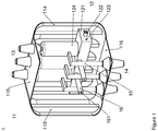
- Figure 1 shows an exemplary gas insulated (GIS) circuit breaker compartment 1 according to the present invention with removed front wall 111 and removed left side wall 112, so that the internal components are visible;
- Figure 2 shows a top view;
- Figure 3 a front view.
- GIS gas insulated
- the enclosure 11 is composed of metallic walls 111-116, preferably made of non-ferromagnetic stainless steel. These metallic walls shall have corrugations 117 and relatively large radii 118 to increase their mechanical stiffness.
- the radius 118 shall be larger than the usual bending radius of the sheet metal processing, and it shall be small enough not to constraint the devices that are inside the compartment, like the circuit breaker 12, or the interfaces, like the bushings 13, 14. Reasonable values for these radii are between 1 cm and 30cm.
- the corrugations can go inside the radii to reinforce the structure and keep the channels for the natural ventilation open at the outside of a compartment and between several compartments.
- the compartment 11 consists of 6 separate walls that are connected by welding. It is further possible and advantageous to manufacture more than one wall in one piece. Then the connection between adjacent walls can be realised by bending the metal sheet.
- back wall 113 and top wall 115 can be manufactured in one piece.
- Back wall 113 and side wall 112 can also be manufactured in one piece, but only the linear section of their connecting edge can be bended; in the region where their radii meet welding will be required.
- the improved mechanical stiffness is not limited to the very wall where it is applied to.
- Figure 2 shows that the length and width of the top wall 115 are shortened due to the fact the adjacent walls have large bending radii, and shorter width and length already result in an increased mechanical stiffness, even when the top wall 115 does not show any corrugations or radii in this example.
- corrugations it is also possible to add corrugations to the top wall 115 or to the bottom wall 116 in case of need.
- a further aspect of the corrugations is that they can improve the stream of cooling air along the outside of the compartment when the corrugations are arranged in a vertical manner and no obstacles block the flow of air.
- the room that the corrugations form between adjacent compartments can also be used for guiding the released gases in case of internal arcing.
- the required means for a controlled pressure release in case of a failure are not shown here.
- the corrugations 117 can either be directed towards the inside the compartment, as shown in the Figures 1-3 , or to the outside (not shown).
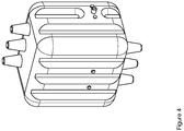
- Figure 4 shows an alternative way of shaping the connection between the front / back wall and the side walls. As here also large bending radii are being used, the mechanical stress to the connections of the walls is reduced.
- Figure 5 shows how additional heat sinks can be added to the corrugations, e.g. by spot welding of a simple piece of sheet metal 130.
- the transfer of heat from the compartment to the stream of cooling air at the outside of the compartment is supported by an increased surface. As warm air has a lower density than cold air, surrounding air will flow from the bottom to the top of the compartment along the vertical corrugations and the heat sink.
- Heat sinks may be added at any place at the outside of the compartment, wherever it is useful for the effective cooling of the panel, i.e. at one or more side walls and at the impressed areas of the wall - as shown in figure 5 - and / or at the salient areas of the wall.
- Figure 6 shows how a side wall - here as an example the back wall 113 - can be equipped with an additional sandwich wall 140.
- This will result in two advantages - first, the mechanical stiffness is remarkably increased when the sandwich wall ist firmly connected to the side wall, e.g. by welding spots distributed on all the areas where the two walls touch.
- the second advantage is the thermosiphon cooling effect inside the compartment due to the chimney that has been build when the sandwich plate 140 leaves openings 141, 142 at its upper and lower end, as shown in figure 7 , where the insulating gas inside the compartment can run between the side wall and the sandwich wall.
- the warmest gas inside the compartment is where the heat or electrical losses are being generated, i.e. in the center where the conductors are.
- the coldest gas is at the side walls, where the surrounding air is cooling the compartment.
- the gas will fall down inside said chimneys between the side walls and the sandwich walls as it is being cooled there. This falling gas will enhance the circulation of insulating gas inside the compartment so that the heat is transported more effectively to the outside of the compartment. Consequently, the compartment can carry higher nominal currents.
- the corrugated walls 111-116 can preferably be made by mechanical pressing, deep drawing or by hydroforming.
- the walls 111-116 can be advantageous to make the walls 111-116 from tailored blaks, so that certain areas of the wall can have different material properties, e.g. sheets with higher stiffness for local reinforcement or regions with improved weldability.
- the second key aspect of this invention is the usage of the compartment internal devices for the reinforcement of the compartment.
- the idea is that at least one mechanical reinforcement is provided by the internal device, e.g. the circuit breaker 12, in at least one of the three spatial directions, to limit bulging of the compartment in any direction.
- front wall 111 and back wall 113 shall be mechanically connected by the gearbox 121 of the circuit breaker 12.
- Fixation means 123 shall be foreseen in the gearbox 121 where it touches the front wall 111 and the back wall 113. Due to this connection, the bulging of the walls 111 and 113 will be strongly reduced when the compartment is pressurised.
- Top wall 115 and bottom wall 116 shall be mechanically connected by the top bushings 13, the switching poles 124, the gearbox 121, the conductors 15 and the bottom bushings 14.
- the circuit breaker 12 is to be designed in a way that the corresponding forces can be borne. Due to this connection, the bulging of the walls 115 and 116 will be strongly reduced when the compartment is pressurised.
- the side walls 112, 114 shall be mechanically connected by the gearbox 121 and by mechanical supports 16 with fixation means 161 that connect both side walls to the gearbox.
- these supports can be conductive or have to be insulating.
- the supports that connect the gearbox to the right side wall 114 can be conductive, while the supports that connect the gearbox to the left side wall 112 will generally have to be insulating as they pass between the conductors of two phases. Due to this connection, the bulging of the walls 112 and 114 will be strongly reduced when the compartment is pressurised.
- fixation means 123, 161 together with the fixation means 17 can e.g. be inside threads 123, 161 for inserting screws 17 to build a fixed structure of wall, internal parts and opposing wall.
- this screw connection through the enclosure does not jeopardisethe gas tightness of the enclosure.
- sealings can be used here, or the heads of the screws can be welded to the walls in a gas-tight manner after insertion.
- fixations do not necessarily require an opening in the walls.
- accessible connections can be fixed before the final closure of the compartment.
- a threaded stud can then be welded to the inside of the wall.
- the shown example includes a massive gearbox running through the entire compartment, therefore it is advantageous to exploit this box for the reinforcement structure.
- the figures show a compartment for a CB as an example.
- the ideas of this invention are also generally usable for all kinds of compartments, e.g. for compartments with three position switches.
Landscapes
- Engineering & Computer Science (AREA)
- Power Engineering (AREA)
- Gas-Insulated Switchgears (AREA)
Abstract
Description
- The invention relates to a Medium voltage gas insulated switchgear with pressure consolidated compartment, with three phase switch with movable contacts, gearbox and bushings, wherein the switchgear is provided with a further inner compartment, containing the switches and the gearbox, which is constructed gas and pressure tight versus the remaining other housing of the switchgear, according to the features of the preamble of
claim 1. - For medium voltage gas insulated switch gears GIS, it is well known, that the insulating gas in the switchgear compartment is used at relatively low pressures, that means, some few hundred mbar above environmental pressure. Such insulating gas can be dry air, N2 or SF6, depending on the nominal voltage and the desired overall dimensions of the switchgear. The compartments of said GIS can then have a simple, rectangular shape. Additional profiles are being used, in some cases to reinforce the structure, to avoid bulging of the side walls of the compartment due to the pressure of the gas, that was filled into the compartment.
- Well known medium voltage GIS compartments are not suitable for the use of insulating gases at higher pressures, e.g. mixtures with fluoroketones at higher pressures than the state of the art or dry air at a pressure of about 3 bar. The bulging of the structure would be excessive. If the thickness of the steel walls of the compartments would be increased to reduce the bulging, the material costs would strongly increase.
- So the object of the invention is, to realize higher insulation gas pressures, by a reduced need of material for the compartment.
- This is solved by the invention, by the features of
claim 1.
Further advantageous embodiments are given by the depending claims 2 to 9. - Subject of the invention is that the compressive strengthening of the aforesaid inner compartment is realized by integrated wall structures, by the use of metal sheets with integral corrugations and edges with large radii.
- In a further advantageous embodiment, the corrugations are oriented in parallel to the long axis, wherein the long axis can be the moving axis of the movable contacts, and with addition of rectangularly to the wallstructures oriented support element of the switches.
- Important is the combination of stiffening structuring of the wall in addition with a rectangular stiffening via the traverse or gearbox, result in combination to an enhanced pressure stability, by the use of reduced material.
- In a further advantageous embodiment, the support element is a traverse, directly fixed with the wall of the inner compartment.
Alternatively or additionally, the support element, or as further stiffening element, can be the aforesaid gearbox directly fixed with the wall of the inner compartment. - So the invention proposes:
- to use metal sheets with corrugations and edges with large radii for the walls of the compartment
and - to use the devices that are anyway required inside the compartment, e.g. circuit breakers, as a reinforcement means for the compartment.
- An advantageous embodiment of the invention is shown in the figures:
-
Figure 1 : Exemplary gas insulated (GIS)circuit breaker compartment 1 -
Figure 2 : Top view -
Figure 3 : Front view -
Figure 4 : Alternative way of shaping -
Figure 5 : Optional heat sinks -
Figure 6 : Optional sandwich structure -
Figure 7 : Thermosiphon cooling -
Figure 1 shows an exemplary gas insulated (GIS)circuit breaker compartment 1 according to the present invention with removedfront wall 111 and removedleft side wall 112, so that the internal components are visible;Figure 2 shows a top view;Figure 3 a front view. - The
enclosure 11 is composed of metallic walls 111-116, preferably made of non-ferromagnetic stainless steel. These metallic walls shall havecorrugations 117 and relativelylarge radii 118 to increase their mechanical stiffness. Theradius 118 shall be larger than the usual bending radius of the sheet metal processing, and it shall be small enough not to constraint the devices that are inside the compartment, like thecircuit breaker 12, or the interfaces, like thebushings - The arrangement of corrugations and radii is advantageous when the resulting welding lines are straight and short.
- Furthermore, the corrugations can go inside the radii to reinforce the structure and keep the channels for the natural ventilation open at the outside of a compartment and between several compartments.
- In the example shown in
Figures 1-3 thecompartment 11 consists of 6 separate walls that are connected by welding. It is further possible and advantageous to manufacture more than one wall in one piece. Then the connection between adjacent walls can be realised by bending the metal sheet. - For example,
back wall 113 andtop wall 115 can be manufactured in one piece.Back wall 113 andside wall 112 can also be manufactured in one piece, but only the linear section of their connecting edge can be bended; in the region where their radii meet welding will be required. The improved mechanical stiffness is not limited to the very wall where it is applied to. -
Figure 2 shows that the length and width of thetop wall 115 are shortened due to the fact the adjacent walls have large bending radii, and shorter width and length already result in an increased mechanical stiffness, even when thetop wall 115 does not show any corrugations or radii in this example. Certainly it is also possible to add corrugations to thetop wall 115 or to thebottom wall 116 in case of need. - A further aspect of the corrugations is that they can improve the stream of cooling air along the outside of the compartment when the corrugations are arranged in a vertical manner and no obstacles block the flow of air.
- This can especially be seen in
Figure 2 . - The room that the corrugations form between adjacent compartments can also be used for guiding the released gases in case of internal arcing. The required means for a controlled pressure release in case of a failure are not shown here. The
corrugations 117 can either be directed towards the inside the compartment, as shown in theFigures 1-3 , or to the outside (not shown). -
Figure 4 shows an alternative way of shaping the connection between the front / back wall and the side walls. As here also large bending radii are being used, the mechanical stress to the connections of the walls is reduced. -
Figure 5 shows how additional heat sinks can be added to the corrugations, e.g. by spot welding of a simple piece of sheet metal 130. The transfer of heat from the compartment to the stream of cooling air at the outside of the compartment is supported by an increased surface. As warm air has a lower density than cold air, surrounding air will flow from the bottom to the top of the compartment along the vertical corrugations and the heat sink.
Heat sinks may be added at any place at the outside of the compartment, wherever it is useful for the effective cooling of the panel, i.e. at one or more side walls and at the impressed areas of the wall - as shown infigure 5 - and / or at the salient areas of the wall. -
Figure 6 shows how a side wall - here as an example the back wall 113 - can be equipped with anadditional sandwich wall 140. This will result in two advantages - first, the mechanical stiffness is remarkably increased when the sandwich wall ist firmly connected to the side wall, e.g. by welding spots distributed on all the areas where the two walls touch.
The second advantage is the thermosiphon cooling effect inside the compartment due to the chimney that has been build when thesandwich plate 140leaves openings figure 7 , where the insulating gas inside the compartment can run between the side wall and the sandwich wall. The warmest gas inside the compartment is where the heat or electrical losses are being generated, i.e. in the center where the conductors are. The coldest gas is at the side walls, where the surrounding air is cooling the compartment. As the density of cold insulating gas is lower than the density of warm insulating gas, the gas will fall down inside said chimneys between the side walls and the sandwich walls as it is being cooled there. This falling gas will enhance the circulation of insulating gas inside the compartment so that the heat is transported more effectively to the outside of the compartment. Consequently, the compartment can carry higher nominal currents. - The corrugated walls 111-116 can preferably be made by mechanical pressing, deep drawing or by hydroforming.
- Further, it can be advantageous to make the walls 111-116 from tailored blaks, so that certain areas of the wall can have different material properties, e.g. sheets with higher stiffness for local reinforcement or regions with improved weldability.
- The second key aspect of this invention is the usage of the compartment internal devices for the reinforcement of the compartment.
The idea is that at least one mechanical reinforcement is provided by the internal device, e.g. thecircuit breaker 12, in at least one of the three spatial directions, to limit bulging of the compartment in any direction. - In the shown example,
front wall 111 andback wall 113 shall be mechanically connected by thegearbox 121 of thecircuit breaker 12. Fixation means 123 shall be foreseen in thegearbox 121 where it touches thefront wall 111 and theback wall 113.
Due to this connection, the bulging of thewalls -
Top wall 115 andbottom wall 116 shall be mechanically connected by thetop bushings 13, the switchingpoles 124, thegearbox 121, theconductors 15 and thebottom bushings 14. Thecircuit breaker 12 is to be designed in a way that the corresponding forces can be borne.
Due to this connection, the bulging of thewalls - The
side walls gearbox 121 and bymechanical supports 16 with fixation means 161 that connect both side walls to the gearbox. Depending on their position inside the compartment, these supports can be conductive or have to be insulating. In the shown example, the supports that connect the gearbox to the right side wall 114 (supports not shown) can be conductive, while the supports that connect the gearbox to theleft side wall 112 will generally have to be insulating as they pass between the conductors of two phases.
Due to this connection, the bulging of thewalls - The mentioned fixation means 123, 161 together with the fixation means 17 can e.g. be
inside threads screws 17 to build a fixed structure of wall, internal parts and opposing wall. - Certainly, it has to be considered that this screw connection through the enclosure does not jeopardisethe gas tightness of the enclosure. E.g. sealings can be used here, or the heads of the screws can be welded to the walls in a gas-tight manner after insertion.
- Said fixations do not necessarily require an opening in the walls. Depending on the sequence of assembly, accessible connections can be fixed before the final closure of the compartment. A threaded stud can then be welded to the inside of the wall.
- The shown example includes a massive gearbox running through the entire compartment, therefore it is advantageous to exploit this box for the reinforcement structure. In other compartments without this gearbox or alike devices, it may be advantageous to use a mechanical support like
part 16, but directly between two opposing walls (not shown). - The figures show a compartment for a CB as an example. Certainly, the ideas of this invention are also generally usable for all kinds of compartments, e.g. for compartments with three position switches.
-
- 1
- Gas insulated circuit breaker compartment
- 11
- Enclosure
- 12
- Circuit Breaker (without drive - drive is external to the compartment)
- 13
- Top bushings
- 14
- Bottom bushings
- 15
- Conductors
- 16
- Mechanical supports
- 17
- Fixation means
- 111
- Front wall
- 112
- Side wall left
- 113
- Back wall
- 114
- Side wall right
- 115
- Top wall
- 116
- Bottom wall
- 117
- Corrugation
- 118
- Radius
- 119
- Welding line
- 121
- Gearbox
- 122
- Drive shaft to mechanically couple the external drive
- 123
- Fixation means
- 124
- Switching poles
- 130
- Heat sink
- 140
- Sandwich wall
- 141
- Upper opening between side wall and sandwich wall
- 142
- Lower opening between side wall and sandwich wall
- 161
- Fixation means
Claims (9)
- Medium voltage gas insulated switchgear with pressure consolidated compartment for one, two or three phases, wherein the switchgear is provided with a further inner compartment, which is constructed gas and pressure tight versus the remaining other housing of the switchgear characterized in that the compressive strengthening of the aforesaid inner compartment is realized by integrated wall structures, by the use of metal sheets with integral corrugations and edges with large radii.
- Medium voltage gas insulated switchgear, according to claim 1, characterized in that the integral corrugations are oriented in parallel to the long exis, wherein the long axis is the moving axis of the movable contacts, and with addition rectangular to the wallstructures oriented support element of the switches.
- Medium voltage gas insulated switchgear, according to claim 1 or 2, characterized in that the inner compartment is further reinforced with one or more internal support elements that are oriented rectangularly to the wallstructures, mechanically connecting one wall with another wall.
- Medium voltage gas insulated switchgear, according to claim 3, characterized in that the support element is a traverse (121), directly fixed with two walls of the inner compartment.
- Medium voltage gas insulated switchgear, according to claim 3 or 4, characterized in that the support element is the aforesaid gearbox or another part of a switch or VCB frame, directly fixed with two walls of the inner compartment.
- Medium voltage gas insulated switchgear, according to one of the preceeding claims, characterized in that the metal sheets with corrugations are produced by the use of hydroforming technology.
- Medium voltage gas insulated switchgear, according to one of the preceeding claims, characterized in that the metal sheets with corrugations consist of tailored blanks.
- Medium voltage gas insulated switchgear, according to one of the preceeding claims, characterized in that the metal sheets with corrugations consist of sandwich profiles.
- Medium voltage gas insulated switchgear, according to one of the preceeding claims, characterized in that heat sinks are added to the corrugations.
Priority Applications (2)
| Application Number | Priority Date | Filing Date | Title |
|---|---|---|---|
| EP17201616.4A EP3483995B1 (en) | 2017-11-14 | 2017-11-14 | Medium voltage gas insulated switchgear with pressure reinforced compartment |
| PCT/EP2018/080843 WO2019096711A1 (en) | 2017-11-14 | 2018-11-09 | Medium voltage gas insulated switchgear with pressure consolidated compartment |
Applications Claiming Priority (1)
| Application Number | Priority Date | Filing Date | Title |
|---|---|---|---|
| EP17201616.4A EP3483995B1 (en) | 2017-11-14 | 2017-11-14 | Medium voltage gas insulated switchgear with pressure reinforced compartment |
Publications (2)
| Publication Number | Publication Date |
|---|---|
| EP3483995A1 true EP3483995A1 (en) | 2019-05-15 |
| EP3483995B1 EP3483995B1 (en) | 2022-09-21 |
Family
ID=60331443
Family Applications (1)
| Application Number | Title | Priority Date | Filing Date |
|---|---|---|---|
| EP17201616.4A Not-in-force EP3483995B1 (en) | 2017-11-14 | 2017-11-14 | Medium voltage gas insulated switchgear with pressure reinforced compartment |
Country Status (2)
| Country | Link |
|---|---|
| EP (1) | EP3483995B1 (en) |
| WO (1) | WO2019096711A1 (en) |
Cited By (10)
| Publication number | Priority date | Publication date | Assignee | Title |
|---|---|---|---|---|
| CN112018651A (en) * | 2020-08-26 | 2020-12-01 | 西安神电(泾阳)电器有限公司 | Method for improving insulating strength of insulating part for environment-friendly gas-filled cabinet and insulating part |
| EP3745548A1 (en) * | 2019-05-29 | 2020-12-02 | Schneider Electric Industries SAS | Gas insulated container |
| CN112350198A (en) * | 2020-11-27 | 2021-02-09 | 余斌 | Automatic power distribution cabinet capable of preventing influence of humid air and using method thereof |
| CN113193506A (en) * | 2020-01-29 | 2021-07-30 | Abb瑞士股份有限公司 | Compartment for medium-pressure air or gas-insulated switchgear |
| US20210249161A1 (en) * | 2020-02-06 | 2021-08-12 | Abb Schweiz Ag | Bushing for a medium voltage switchgear |
| WO2022167491A1 (en) * | 2021-02-05 | 2022-08-11 | Schneider Electric Industries Sas | Pressure vessel |
| CN116260067A (en) * | 2023-03-24 | 2023-06-13 | 江苏大全长江电器股份有限公司 | A 72.5kV single-tank environmentally friendly gas-insulated GIS structure for offshore wind power towers |
| EP4475362A1 (en) * | 2023-06-05 | 2024-12-11 | Abb Schweiz Ag | Switchgear and electrical assembly |
| EP4485719A1 (en) * | 2023-06-30 | 2025-01-01 | Abb Schweiz Ag | A metal enclosure for electrical switchgear |
| EP4485720A1 (en) * | 2023-06-30 | 2025-01-01 | Abb Schweiz Ag | A metal enclosure for electrical switchgear |
Families Citing this family (2)
| Publication number | Priority date | Publication date | Assignee | Title |
|---|---|---|---|---|
| ES2943533T3 (en) * | 2020-07-20 | 2023-06-14 | Abb Schweiz Ag | circuit breaker compartment |
| CN116706755B (en) * | 2023-07-28 | 2023-10-20 | 四川宝光电器设备有限公司 | Environment-friendly gas-insulated inflatable cabinet |
Citations (8)
| Publication number | Priority date | Publication date | Assignee | Title |
|---|---|---|---|---|
| DE2610309A1 (en) * | 1976-03-12 | 1977-09-15 | Calor Emag Elektrizitaets Ag | Metal clad gas insulated HV switchgear - has ratio of inner to outer pressure kept nearly constant |
| JPH03295212A (en) * | 1990-04-13 | 1991-12-26 | Toshiba Corp | Panel radiator for gas-insulated machine |
| DE4107725C1 (en) * | 1991-03-11 | 1992-09-10 | Sachsenwerk Ag, 8400 Regensburg, De | Encapsulated three=phase medium voltage switchgear - is filled with insulating gas with diverters mounted in series and transformers in outlet chamber |
| EP0871269A1 (en) * | 1997-04-08 | 1998-10-14 | Gec Alsthom T & D Sa | Gas-tight, metal housing for an electric energy distribution unit |
| DE29912027U1 (en) * | 1999-07-02 | 1999-09-23 | Siemens AG, 80333 München | Containers for switchgear, in particular for gas-insulated medium-voltage switchgear |
| EP1211771A1 (en) * | 2000-11-30 | 2002-06-05 | Mitsubishi Denki Kabushiki Kaisha | Gas-filled switching apparatus |
| EP1237246A1 (en) * | 2001-03-01 | 2002-09-04 | Siemens Aktiengesellschaft | Housing for a gas insulated switchgear with a heat exchanger |
| WO2010142302A1 (en) * | 2009-06-08 | 2010-12-16 | Abb Technology Ag | Metal encapsulation for switch gear, and method for manufacturing the same |
-
2017
- 2017-11-14 EP EP17201616.4A patent/EP3483995B1/en not_active Not-in-force
-
2018
- 2018-11-09 WO PCT/EP2018/080843 patent/WO2019096711A1/en not_active Ceased
Patent Citations (8)
| Publication number | Priority date | Publication date | Assignee | Title |
|---|---|---|---|---|
| DE2610309A1 (en) * | 1976-03-12 | 1977-09-15 | Calor Emag Elektrizitaets Ag | Metal clad gas insulated HV switchgear - has ratio of inner to outer pressure kept nearly constant |
| JPH03295212A (en) * | 1990-04-13 | 1991-12-26 | Toshiba Corp | Panel radiator for gas-insulated machine |
| DE4107725C1 (en) * | 1991-03-11 | 1992-09-10 | Sachsenwerk Ag, 8400 Regensburg, De | Encapsulated three=phase medium voltage switchgear - is filled with insulating gas with diverters mounted in series and transformers in outlet chamber |
| EP0871269A1 (en) * | 1997-04-08 | 1998-10-14 | Gec Alsthom T & D Sa | Gas-tight, metal housing for an electric energy distribution unit |
| DE29912027U1 (en) * | 1999-07-02 | 1999-09-23 | Siemens AG, 80333 München | Containers for switchgear, in particular for gas-insulated medium-voltage switchgear |
| EP1211771A1 (en) * | 2000-11-30 | 2002-06-05 | Mitsubishi Denki Kabushiki Kaisha | Gas-filled switching apparatus |
| EP1237246A1 (en) * | 2001-03-01 | 2002-09-04 | Siemens Aktiengesellschaft | Housing for a gas insulated switchgear with a heat exchanger |
| WO2010142302A1 (en) * | 2009-06-08 | 2010-12-16 | Abb Technology Ag | Metal encapsulation for switch gear, and method for manufacturing the same |
Cited By (16)
| Publication number | Priority date | Publication date | Assignee | Title |
|---|---|---|---|---|
| EP3745548A1 (en) * | 2019-05-29 | 2020-12-02 | Schneider Electric Industries SAS | Gas insulated container |
| US11909181B2 (en) | 2020-01-29 | 2024-02-20 | Abb Schweiz Ag | Compartment for a medium voltage air or gas insulated switchgear |
| CN113193506A (en) * | 2020-01-29 | 2021-07-30 | Abb瑞士股份有限公司 | Compartment for medium-pressure air or gas-insulated switchgear |
| EP3859914A1 (en) * | 2020-01-29 | 2021-08-04 | ABB Schweiz AG | Compartment for a medium voltage air or gas insulated switchgear |
| CN113193506B (en) * | 2020-01-29 | 2024-12-13 | Abb瑞士股份有限公司 | Compartment for medium voltage air or gas insulated switchgear |
| US20210249161A1 (en) * | 2020-02-06 | 2021-08-12 | Abb Schweiz Ag | Bushing for a medium voltage switchgear |
| US11742114B2 (en) * | 2020-02-06 | 2023-08-29 | Abb Schweiz Ag | Bushing for a medium voltage switchgear |
| CN112018651B (en) * | 2020-08-26 | 2022-04-01 | 西安神电(泾阳)电器有限公司 | Method for improving insulating strength of insulating part for environment-friendly gas-filled cabinet and insulating part |
| CN112018651A (en) * | 2020-08-26 | 2020-12-01 | 西安神电(泾阳)电器有限公司 | Method for improving insulating strength of insulating part for environment-friendly gas-filled cabinet and insulating part |
| CN112350198A (en) * | 2020-11-27 | 2021-02-09 | 余斌 | Automatic power distribution cabinet capable of preventing influence of humid air and using method thereof |
| CN112350198B (en) * | 2020-11-27 | 2021-06-25 | 秦皇岛金胜达配电开关控制设备制造有限公司 | Automatic power distribution cabinet capable of preventing influence of humid air and using method thereof |
| WO2022167491A1 (en) * | 2021-02-05 | 2022-08-11 | Schneider Electric Industries Sas | Pressure vessel |
| CN116260067A (en) * | 2023-03-24 | 2023-06-13 | 江苏大全长江电器股份有限公司 | A 72.5kV single-tank environmentally friendly gas-insulated GIS structure for offshore wind power towers |
| EP4475362A1 (en) * | 2023-06-05 | 2024-12-11 | Abb Schweiz Ag | Switchgear and electrical assembly |
| EP4485719A1 (en) * | 2023-06-30 | 2025-01-01 | Abb Schweiz Ag | A metal enclosure for electrical switchgear |
| EP4485720A1 (en) * | 2023-06-30 | 2025-01-01 | Abb Schweiz Ag | A metal enclosure for electrical switchgear |
Also Published As
| Publication number | Publication date |
|---|---|
| EP3483995B1 (en) | 2022-09-21 |
| WO2019096711A1 (en) | 2019-05-23 |
Similar Documents
| Publication | Publication Date | Title |
|---|---|---|
| EP3483995B1 (en) | Medium voltage gas insulated switchgear with pressure reinforced compartment | |
| US5124881A (en) | Enclosed switchgear | |
| US8481881B2 (en) | Electric circuit breaker and switchgear panel with circuit breaker | |
| US3636237A (en) | Bus duct | |
| CN102687228B (en) | Medium voltage circuit breaker arrangement | |
| KR101433004B1 (en) | Heat sink busbar and switchgear having thereof | |
| US8963670B2 (en) | Tap changer | |
| US7286337B2 (en) | Switching device for power distribution | |
| JPS62144506A (en) | Gas insulated switchgear | |
| EP0459593B1 (en) | Compartment module for a metal-enclosed, modular medium-voltage distribution system and a distribution system assembled with these compartment modules | |
| CN103403833A (en) | Sealed circuit breaker | |
| US10153110B2 (en) | Vacuum circuit breaker | |
| JP2005304200A (en) | Gas insulated switchgear | |
| HK1245994A1 (en) | Vacuum circuit breaker | |
| CN1065354C (en) | Power distribution device enclosed in a metal box with a vacuum switchgear | |
| EP1772883B1 (en) | A medium-voltage vacuum circuit breaker and a related medium-voltage switchboard | |
| US3348103A (en) | Class 1, division 2, panel board | |
| CN1197215C (en) | Container for distribution equipment, in particular, used for gas insulated medium voltage distribution equipment | |
| JP4726661B2 (en) | Switchgear | |
| CN101901715B (en) | breaker | |
| CN101842950B (en) | Electromagnetic contactor | |
| CN1008961B (en) | Switching apparatus | |
| JP2573313B2 (en) | Self-cooling gas-insulated transformer with non-voltage tap changer | |
| KR20180000846U (en) | Switchgear | |
| CN113243067A (en) | Compartment for medium-voltage gas-insulated switchgear |
Legal Events
| Date | Code | Title | Description |
|---|---|---|---|
| PUAI | Public reference made under article 153(3) epc to a published international application that has entered the european phase |
Free format text: ORIGINAL CODE: 0009012 |
|
| STAA | Information on the status of an ep patent application or granted ep patent |
Free format text: STATUS: THE APPLICATION HAS BEEN PUBLISHED |
|
| AK | Designated contracting states |
Kind code of ref document: A1 Designated state(s): AL AT BE BG CH CY CZ DE DK EE ES FI FR GB GR HR HU IE IS IT LI LT LU LV MC MK MT NL NO PL PT RO RS SE SI SK SM TR |
|
| AX | Request for extension of the european patent |
Extension state: BA ME |
|
| STAA | Information on the status of an ep patent application or granted ep patent |
Free format text: STATUS: REQUEST FOR EXAMINATION WAS MADE |
|
| 17P | Request for examination filed |
Effective date: 20191115 |
|
| RBV | Designated contracting states (corrected) |
Designated state(s): AL AT BE BG CH CY CZ DE DK EE ES FI FR GB GR HR HU IE IS IT LI LT LU LV MC MK MT NL NO PL PT RO RS SE SI SK SM TR |
|
| STAA | Information on the status of an ep patent application or granted ep patent |
Free format text: STATUS: EXAMINATION IS IN PROGRESS |
|
| 17Q | First examination report despatched |
Effective date: 20210301 |
|
| GRAP | Despatch of communication of intention to grant a patent |
Free format text: ORIGINAL CODE: EPIDOSNIGR1 |
|
| STAA | Information on the status of an ep patent application or granted ep patent |
Free format text: STATUS: GRANT OF PATENT IS INTENDED |
|
| RIC1 | Information provided on ipc code assigned before grant |
Ipc: H02B 1/56 20060101ALN20220324BHEP Ipc: H02B 13/045 20060101AFI20220324BHEP |
|
| INTG | Intention to grant announced |
Effective date: 20220419 |
|
| GRAS | Grant fee paid |
Free format text: ORIGINAL CODE: EPIDOSNIGR3 |
|
| GRAA | (expected) grant |
Free format text: ORIGINAL CODE: 0009210 |
|
| STAA | Information on the status of an ep patent application or granted ep patent |
Free format text: STATUS: THE PATENT HAS BEEN GRANTED |
|
| AK | Designated contracting states |
Kind code of ref document: B1 Designated state(s): AL AT BE BG CH CY CZ DE DK EE ES FI FR GB GR HR HU IE IS IT LI LT LU LV MC MK MT NL NO PL PT RO RS SE SI SK SM TR |
|
| RAP3 | Party data changed (applicant data changed or rights of an application transferred) |
Owner name: ABB SCHWEIZ AG |
|
| REG | Reference to a national code |
Ref country code: GB Ref legal event code: FG4D |
|
| RIN1 | Information on inventor provided before grant (corrected) |
Inventor name: REUBER, CHRISTIAN Inventor name: KOPP, DALIBOR Inventor name: GENTSCH, DIETMAR |
|
| REG | Reference to a national code |
Ref country code: CH Ref legal event code: EP |
|
| REG | Reference to a national code |
Ref country code: IE Ref legal event code: FG4D |
|
| REG | Reference to a national code |
Ref country code: DE Ref legal event code: R096 Ref document number: 602017061933 Country of ref document: DE |
|
| REG | Reference to a national code |
Ref country code: AT Ref legal event code: REF Ref document number: 1520440 Country of ref document: AT Kind code of ref document: T Effective date: 20221015 |
|
| REG | Reference to a national code |
Ref country code: LT Ref legal event code: MG9D |
|
| REG | Reference to a national code |
Ref country code: NL Ref legal event code: MP Effective date: 20220921 |
|
| PG25 | Lapsed in a contracting state [announced via postgrant information from national office to epo] |
Ref country code: SE Free format text: LAPSE BECAUSE OF FAILURE TO SUBMIT A TRANSLATION OF THE DESCRIPTION OR TO PAY THE FEE WITHIN THE PRESCRIBED TIME-LIMIT Effective date: 20220921 Ref country code: RS Free format text: LAPSE BECAUSE OF FAILURE TO SUBMIT A TRANSLATION OF THE DESCRIPTION OR TO PAY THE FEE WITHIN THE PRESCRIBED TIME-LIMIT Effective date: 20220921 Ref country code: NO Free format text: LAPSE BECAUSE OF FAILURE TO SUBMIT A TRANSLATION OF THE DESCRIPTION OR TO PAY THE FEE WITHIN THE PRESCRIBED TIME-LIMIT Effective date: 20221221 Ref country code: LV Free format text: LAPSE BECAUSE OF FAILURE TO SUBMIT A TRANSLATION OF THE DESCRIPTION OR TO PAY THE FEE WITHIN THE PRESCRIBED TIME-LIMIT Effective date: 20220921 Ref country code: LT Free format text: LAPSE BECAUSE OF FAILURE TO SUBMIT A TRANSLATION OF THE DESCRIPTION OR TO PAY THE FEE WITHIN THE PRESCRIBED TIME-LIMIT Effective date: 20220921 Ref country code: FI Free format text: LAPSE BECAUSE OF FAILURE TO SUBMIT A TRANSLATION OF THE DESCRIPTION OR TO PAY THE FEE WITHIN THE PRESCRIBED TIME-LIMIT Effective date: 20220921 |
|
| REG | Reference to a national code |
Ref country code: AT Ref legal event code: MK05 Ref document number: 1520440 Country of ref document: AT Kind code of ref document: T Effective date: 20220921 |
|
| PG25 | Lapsed in a contracting state [announced via postgrant information from national office to epo] |
Ref country code: HR Free format text: LAPSE BECAUSE OF FAILURE TO SUBMIT A TRANSLATION OF THE DESCRIPTION OR TO PAY THE FEE WITHIN THE PRESCRIBED TIME-LIMIT Effective date: 20220921 Ref country code: GR Free format text: LAPSE BECAUSE OF FAILURE TO SUBMIT A TRANSLATION OF THE DESCRIPTION OR TO PAY THE FEE WITHIN THE PRESCRIBED TIME-LIMIT Effective date: 20221222 |
|
| PG25 | Lapsed in a contracting state [announced via postgrant information from national office to epo] |
Ref country code: SM Free format text: LAPSE BECAUSE OF FAILURE TO SUBMIT A TRANSLATION OF THE DESCRIPTION OR TO PAY THE FEE WITHIN THE PRESCRIBED TIME-LIMIT Effective date: 20220921 Ref country code: RO Free format text: LAPSE BECAUSE OF FAILURE TO SUBMIT A TRANSLATION OF THE DESCRIPTION OR TO PAY THE FEE WITHIN THE PRESCRIBED TIME-LIMIT Effective date: 20220921 Ref country code: PT Free format text: LAPSE BECAUSE OF FAILURE TO SUBMIT A TRANSLATION OF THE DESCRIPTION OR TO PAY THE FEE WITHIN THE PRESCRIBED TIME-LIMIT Effective date: 20230123 Ref country code: ES Free format text: LAPSE BECAUSE OF FAILURE TO SUBMIT A TRANSLATION OF THE DESCRIPTION OR TO PAY THE FEE WITHIN THE PRESCRIBED TIME-LIMIT Effective date: 20220921 Ref country code: CZ Free format text: LAPSE BECAUSE OF FAILURE TO SUBMIT A TRANSLATION OF THE DESCRIPTION OR TO PAY THE FEE WITHIN THE PRESCRIBED TIME-LIMIT Effective date: 20220921 Ref country code: AT Free format text: LAPSE BECAUSE OF FAILURE TO SUBMIT A TRANSLATION OF THE DESCRIPTION OR TO PAY THE FEE WITHIN THE PRESCRIBED TIME-LIMIT Effective date: 20220921 |
|
| PG25 | Lapsed in a contracting state [announced via postgrant information from national office to epo] |
Ref country code: SK Free format text: LAPSE BECAUSE OF FAILURE TO SUBMIT A TRANSLATION OF THE DESCRIPTION OR TO PAY THE FEE WITHIN THE PRESCRIBED TIME-LIMIT Effective date: 20220921 Ref country code: PL Free format text: LAPSE BECAUSE OF FAILURE TO SUBMIT A TRANSLATION OF THE DESCRIPTION OR TO PAY THE FEE WITHIN THE PRESCRIBED TIME-LIMIT Effective date: 20220921 Ref country code: IS Free format text: LAPSE BECAUSE OF FAILURE TO SUBMIT A TRANSLATION OF THE DESCRIPTION OR TO PAY THE FEE WITHIN THE PRESCRIBED TIME-LIMIT Effective date: 20230121 Ref country code: EE Free format text: LAPSE BECAUSE OF FAILURE TO SUBMIT A TRANSLATION OF THE DESCRIPTION OR TO PAY THE FEE WITHIN THE PRESCRIBED TIME-LIMIT Effective date: 20220921 |
|
| REG | Reference to a national code |
Ref country code: DE Ref legal event code: R097 Ref document number: 602017061933 Country of ref document: DE |
|
| PG25 | Lapsed in a contracting state [announced via postgrant information from national office to epo] |
Ref country code: NL Free format text: LAPSE BECAUSE OF FAILURE TO SUBMIT A TRANSLATION OF THE DESCRIPTION OR TO PAY THE FEE WITHIN THE PRESCRIBED TIME-LIMIT Effective date: 20220921 Ref country code: MC Free format text: LAPSE BECAUSE OF FAILURE TO SUBMIT A TRANSLATION OF THE DESCRIPTION OR TO PAY THE FEE WITHIN THE PRESCRIBED TIME-LIMIT Effective date: 20220921 Ref country code: AL Free format text: LAPSE BECAUSE OF FAILURE TO SUBMIT A TRANSLATION OF THE DESCRIPTION OR TO PAY THE FEE WITHIN THE PRESCRIBED TIME-LIMIT Effective date: 20220921 |
|
| REG | Reference to a national code |
Ref country code: CH Ref legal event code: PL |
|
| REG | Reference to a national code |
Ref country code: BE Ref legal event code: MM Effective date: 20221130 |
|
| PLBE | No opposition filed within time limit |
Free format text: ORIGINAL CODE: 0009261 |
|
| STAA | Information on the status of an ep patent application or granted ep patent |
Free format text: STATUS: NO OPPOSITION FILED WITHIN TIME LIMIT |
|
| PG25 | Lapsed in a contracting state [announced via postgrant information from national office to epo] |
Ref country code: LI Free format text: LAPSE BECAUSE OF NON-PAYMENT OF DUE FEES Effective date: 20221130 Ref country code: DK Free format text: LAPSE BECAUSE OF FAILURE TO SUBMIT A TRANSLATION OF THE DESCRIPTION OR TO PAY THE FEE WITHIN THE PRESCRIBED TIME-LIMIT Effective date: 20220921 Ref country code: CH Free format text: LAPSE BECAUSE OF NON-PAYMENT OF DUE FEES Effective date: 20221130 |
|
| GBPC | Gb: european patent ceased through non-payment of renewal fee |
Effective date: 20221221 |
|
| 26N | No opposition filed |
Effective date: 20230622 |
|
| PG25 | Lapsed in a contracting state [announced via postgrant information from national office to epo] |
Ref country code: SI Free format text: LAPSE BECAUSE OF FAILURE TO SUBMIT A TRANSLATION OF THE DESCRIPTION OR TO PAY THE FEE WITHIN THE PRESCRIBED TIME-LIMIT Effective date: 20220921 Ref country code: LU Free format text: LAPSE BECAUSE OF NON-PAYMENT OF DUE FEES Effective date: 20221114 |
|
| PG25 | Lapsed in a contracting state [announced via postgrant information from national office to epo] |
Ref country code: IE Free format text: LAPSE BECAUSE OF NON-PAYMENT OF DUE FEES Effective date: 20221114 Ref country code: GB Free format text: LAPSE BECAUSE OF NON-PAYMENT OF DUE FEES Effective date: 20221221 |
|
| PG25 | Lapsed in a contracting state [announced via postgrant information from national office to epo] |
Ref country code: BE Free format text: LAPSE BECAUSE OF NON-PAYMENT OF DUE FEES Effective date: 20221130 |
|
| PGFP | Annual fee paid to national office [announced via postgrant information from national office to epo] |
Ref country code: FR Payment date: 20231120 Year of fee payment: 7 Ref country code: DE Payment date: 20231121 Year of fee payment: 7 |
|
| PG25 | Lapsed in a contracting state [announced via postgrant information from national office to epo] |
Ref country code: HU Free format text: LAPSE BECAUSE OF FAILURE TO SUBMIT A TRANSLATION OF THE DESCRIPTION OR TO PAY THE FEE WITHIN THE PRESCRIBED TIME-LIMIT; INVALID AB INITIO Effective date: 20171114 |
|
| PG25 | Lapsed in a contracting state [announced via postgrant information from national office to epo] |
Ref country code: CY Free format text: LAPSE BECAUSE OF FAILURE TO SUBMIT A TRANSLATION OF THE DESCRIPTION OR TO PAY THE FEE WITHIN THE PRESCRIBED TIME-LIMIT Effective date: 20220921 |
|
| PG25 | Lapsed in a contracting state [announced via postgrant information from national office to epo] |
Ref country code: MK Free format text: LAPSE BECAUSE OF FAILURE TO SUBMIT A TRANSLATION OF THE DESCRIPTION OR TO PAY THE FEE WITHIN THE PRESCRIBED TIME-LIMIT Effective date: 20220921 Ref country code: IT Free format text: LAPSE BECAUSE OF FAILURE TO SUBMIT A TRANSLATION OF THE DESCRIPTION OR TO PAY THE FEE WITHIN THE PRESCRIBED TIME-LIMIT Effective date: 20220921 |
|
| PG25 | Lapsed in a contracting state [announced via postgrant information from national office to epo] |
Ref country code: BG Free format text: LAPSE BECAUSE OF FAILURE TO SUBMIT A TRANSLATION OF THE DESCRIPTION OR TO PAY THE FEE WITHIN THE PRESCRIBED TIME-LIMIT Effective date: 20220921 |
|
| PG25 | Lapsed in a contracting state [announced via postgrant information from national office to epo] |
Ref country code: MT Free format text: LAPSE BECAUSE OF FAILURE TO SUBMIT A TRANSLATION OF THE DESCRIPTION OR TO PAY THE FEE WITHIN THE PRESCRIBED TIME-LIMIT Effective date: 20220921 |
|
| REG | Reference to a national code |
Ref country code: DE Ref legal event code: R119 Ref document number: 602017061933 Country of ref document: DE |
|
| PG25 | Lapsed in a contracting state [announced via postgrant information from national office to epo] |
Ref country code: DE Free format text: LAPSE BECAUSE OF NON-PAYMENT OF DUE FEES Effective date: 20250603 |
|
| PG25 | Lapsed in a contracting state [announced via postgrant information from national office to epo] |
Ref country code: FR Free format text: LAPSE BECAUSE OF NON-PAYMENT OF DUE FEES Effective date: 20241130 |
|
| PG25 | Lapsed in a contracting state [announced via postgrant information from national office to epo] |
Ref country code: TR Free format text: LAPSE BECAUSE OF FAILURE TO SUBMIT A TRANSLATION OF THE DESCRIPTION OR TO PAY THE FEE WITHIN THE PRESCRIBED TIME-LIMIT Effective date: 20220921 |