EP3483901A2 - Integrierte magnetelemente - Google Patents
Integrierte magnetelemente Download PDFInfo
- Publication number
- EP3483901A2 EP3483901A2 EP18185468.8A EP18185468A EP3483901A2 EP 3483901 A2 EP3483901 A2 EP 3483901A2 EP 18185468 A EP18185468 A EP 18185468A EP 3483901 A2 EP3483901 A2 EP 3483901A2
- Authority
- EP
- European Patent Office
- Prior art keywords
- magnetic
- core
- side pillar
- core frame
- pillar
- Prior art date
- Legal status (The legal status is an assumption and is not a legal conclusion. Google has not performed a legal analysis and makes no representation as to the accuracy of the status listed.)
- Granted
Links
Images


Classifications
-
- H—ELECTRICITY
- H01—ELECTRIC ELEMENTS
- H01F—MAGNETS; INDUCTANCES; TRANSFORMERS; SELECTION OF MATERIALS FOR THEIR MAGNETIC PROPERTIES
- H01F17/00—Fixed inductances of the signal type
- H01F17/04—Fixed inductances of the signal type with magnetic core
- H01F17/045—Fixed inductances of the signal type with magnetic core with core of cylindric geometry and coil wound along its longitudinal axis, i.e. rod or drum core
-
- H—ELECTRICITY
- H01—ELECTRIC ELEMENTS
- H01F—MAGNETS; INDUCTANCES; TRANSFORMERS; SELECTION OF MATERIALS FOR THEIR MAGNETIC PROPERTIES
- H01F27/00—Details of transformers or inductances, in general
- H01F27/24—Magnetic cores
- H01F27/245—Magnetic cores made from sheets, e.g. grain-oriented
-
- H—ELECTRICITY
- H01—ELECTRIC ELEMENTS
- H01F—MAGNETS; INDUCTANCES; TRANSFORMERS; SELECTION OF MATERIALS FOR THEIR MAGNETIC PROPERTIES
- H01F27/00—Details of transformers or inductances, in general
- H01F27/24—Magnetic cores
-
- H—ELECTRICITY
- H01—ELECTRIC ELEMENTS
- H01F—MAGNETS; INDUCTANCES; TRANSFORMERS; SELECTION OF MATERIALS FOR THEIR MAGNETIC PROPERTIES
- H01F27/00—Details of transformers or inductances, in general
- H01F27/28—Coils; Windings; Conductive connections
- H01F27/30—Fastening or clamping coils, windings, or parts thereof together; Fastening or mounting coils or windings on core, casing, or other support
- H01F27/306—Fastening or mounting coils or windings on core, casing or other support
-
- H—ELECTRICITY
- H01—ELECTRIC ELEMENTS
- H01F—MAGNETS; INDUCTANCES; TRANSFORMERS; SELECTION OF MATERIALS FOR THEIR MAGNETIC PROPERTIES
- H01F27/00—Details of transformers or inductances, in general
- H01F27/34—Special means for preventing or reducing unwanted electric or magnetic effects, e.g. no-load losses, reactive currents, harmonics, oscillations, leakage fields
- H01F27/38—Auxiliary core members; Auxiliary coils or windings
-
- H—ELECTRICITY
- H01—ELECTRIC ELEMENTS
- H01F—MAGNETS; INDUCTANCES; TRANSFORMERS; SELECTION OF MATERIALS FOR THEIR MAGNETIC PROPERTIES
- H01F27/00—Details of transformers or inductances, in general
- H01F27/40—Structural association with built-in electric component, e.g. fuse
-
- H—ELECTRICITY
- H01—ELECTRIC ELEMENTS
- H01F—MAGNETS; INDUCTANCES; TRANSFORMERS; SELECTION OF MATERIALS FOR THEIR MAGNETIC PROPERTIES
- H01F3/00—Cores, Yokes, or armatures
- H01F3/10—Composite arrangements of magnetic circuits
-
- H—ELECTRICITY
- H01—ELECTRIC ELEMENTS
- H01F—MAGNETS; INDUCTANCES; TRANSFORMERS; SELECTION OF MATERIALS FOR THEIR MAGNETIC PROPERTIES
- H01F3/00—Cores, Yokes, or armatures
- H01F3/10—Composite arrangements of magnetic circuits
- H01F3/14—Constrictions; Gaps, e.g. air-gaps
-
- H—ELECTRICITY
- H01—ELECTRIC ELEMENTS
- H01F—MAGNETS; INDUCTANCES; TRANSFORMERS; SELECTION OF MATERIALS FOR THEIR MAGNETIC PROPERTIES
- H01F30/00—Fixed transformers not covered by group H01F19/00
- H01F30/06—Fixed transformers not covered by group H01F19/00 characterised by the structure
- H01F30/12—Two-phase, three-phase or polyphase transformers
-
- H—ELECTRICITY
- H01—ELECTRIC ELEMENTS
- H01F—MAGNETS; INDUCTANCES; TRANSFORMERS; SELECTION OF MATERIALS FOR THEIR MAGNETIC PROPERTIES
- H01F37/00—Fixed inductances not covered by group H01F17/00
-
- H—ELECTRICITY
- H02—GENERATION; CONVERSION OR DISTRIBUTION OF ELECTRIC POWER
- H02J—ELECTRIC POWER NETWORKS; CIRCUIT ARRANGEMENTS OR SYSTEMS FOR SUPPLYING OR DISTRIBUTING ELECTRIC POWER; SYSTEMS FOR STORING ELECTRIC ENERGY
- H02J3/00—Circuit arrangements for AC mains or AC distribution networks
- H02J3/01—Arrangements for reducing harmonics or ripples
-
- H—ELECTRICITY
- H02—GENERATION; CONVERSION OR DISTRIBUTION OF ELECTRIC POWER
- H02K—DYNAMO-ELECTRIC MACHINES
- H02K3/00—Details of windings
- H02K3/04—Windings characterised by the conductor shape, form or construction, e.g. with bar conductors
- H02K3/28—Layout of windings or of connections between windings
-
- H—ELECTRICITY
- H01—ELECTRIC ELEMENTS
- H01F—MAGNETS; INDUCTANCES; TRANSFORMERS; SELECTION OF MATERIALS FOR THEIR MAGNETIC PROPERTIES
- H01F3/00—Cores, Yokes, or armatures
- H01F3/10—Composite arrangements of magnetic circuits
- H01F2003/106—Magnetic circuits using combinations of different magnetic materials
-
- H—ELECTRICITY
- H01—ELECTRIC ELEMENTS
- H01F—MAGNETS; INDUCTANCES; TRANSFORMERS; SELECTION OF MATERIALS FOR THEIR MAGNETIC PROPERTIES
- H01F17/00—Fixed inductances of the signal type
- H01F2017/0093—Common mode choke coil
Definitions
- the application relates in general to an integrated magnetic element, and in particular to an integrated magnetic element having common-mode effect and different-mode effects at the same time.
- EMI electromagnetic interference
- a common practice employed for preventing noise from entering electronic devices is to adapt a filter circuit.
- the filter circuits that are commonly used to eliminate noise have some obvious defects.
- the magnetic core of the filter circuit is usually made of a silicon steel sheet, but the high-frequency characteristics of the silicon steel sheet are poor, and when the inductor is made of a silicon steel sheet, it has worse effect at high frequency, which means that the filtering efficiency must be enhanced with additional components.
- a pair of grounding capacitors may need to be added to the P, N input terminals in the structure of the two-phase reactor, but these capacitors may increase the leakage current and also increase the size and complexity of the device. Therefore, how to provide a magnetic element with both better common-mode and differential-mode filtering effects at the same time is a problem that needs to be solved immediately.
- An embodiment of the present invention provides an integrated magnetic element, including a first magnetic-core frame, three second magnetic-core frames, and three coil windings.
- the first magnetic-core frame has a first side pillar and a second side pillar opposite to the first side pillar.
- Three second magnetic-core frames are arranged on a side corresponding to the first side pillar of the first magnetic-core frame, and are arranged in parallel with the axis of the first side pillar of the first magnetic-core frame.
- Each of the second magnetic-core frames has a first side pillar adjacent to the first side pillar of the first magnetic-core frame, and a second side pillar opposite to the first side pillar of itself.
- Three coil windings are connected to a three-phase grid, and wind around the first side pillar of the first magnetic-core frame and the corresponding first side pillar of the second magnetic-core frame respectively.
- the first magnetic-core frame has a first side pillar and a second side pillar opposite to the first side pillar.
- Three second magnetic cores are arranged on a side of the first side pillar of the first magnetic-core frame, and are arranged in parallel with the axis of the first side pillar of the first magnetic-core frame.
- Each of the second magnetic-core frames has a first side pillar adjacent to the first side pillar of the first magnetic-core frame, and a second side pillar opposite to the first side pillar of itself.
- the third magnetic-core frame is arranged on a side of the second side pillar of the three second magnetic-core frames, and has a first side pillar adjacent to the second side pillar of the three second magnetic-core frames and a second side pillar opposite to the first side pillar of itself.
- Three first coil windings are connected to a three-phase grid, and respectively winds around the first side pillar of the first magnetic-core frame and the corresponding first side pillar of the second magnetic-core frame.
- Three second coil windings respectively winds around the corresponding second side pillar of the second magnetic-core frame and the first side pillar of the third magnetic-core frame.
- Another embodiment of the present invention provides an integrated magnetic element, including a magnetic-core frame, three C-type magnetic cores and three coil windings.
- the magnetic-core frame has a first side pillar and a second side pillar opposite to the first side pillar.
- Three C-type magnetic cores are arranged on a side corresponding to the first side pillar of the magnetic-core frame, and are arranged in parallel with the axis of the first side pillar of the magnetic-core frame.
- Each of the C-type magnetic cores has a side pillar adjacent to the first side pillar of the magnetic-core frame.
- the three coil windings are connected to the output terminal of a VFD (Variable-frequency Drive) system, and respectively winds around the first side pillar of the magnetic-core frame and the corresponding side pillar of the C-type magnetic core.
- VFD Very-frequency Drive
- Each of the C-type magnetic cores has a gap, located on a side opposite to the side pillar of itself, and each of the gaps has a Hall sensor disposed therein.
- the magnetic-core frame has a first side pillar and a second side pillar opposite to the first side pillar.
- the first C-type magnetic core is arranged on a side of the first side pillar of the magnetic-core frame, and has a side pillar adjacent to the first side pillar of the magnetic-core frame.
- the second C-type magnetic core is arranged on a side of the second side pillar of the magnetic-core frame, and has a side pillar adjacent to the second side pillar of the magnetic-core frame.
- the first coil winding winds around the first side pillar of the magnetic-core frame and the side pillar of the first C-type magnetic core.
- the second coil winding winds around the second side pillar of the magnetic-core frame and the side pillar of the second C-type magnetic core.
- the first C-type magnetic core has a gap located opposite to the side pillar of itself, and the second C-type magnetic core has a gap located opposite to the side pillar of itself.
- the first coil winding and the second coil winding have the same winding direction.
- the magnetic-core frame has a first side pillar and a second side pillar opposite to the first side pillar.
- the core module includes an E-type magnetic core and an I-type magnetic core.
- the E-type magnetic core has a center pillar, a first side pillar, a second side pillar and a third side pillar.
- the third side pillar is perpendicular to the center pillar, the first side pillar and the second side pillar of the E-type magnetic core.
- the I-type magnetic core is parallel to the third side pillar of the E-type magnetic core, and is arranged on the side corresponding to the third side pillar of the E-type magnetic core.
- a gap between the I-type magnetic core and the first side pillar of the E-type magnetic core and a gap between the I-type magnetic core and the second side pillar of the E-type magnetic core have the same size.
- the first coil winding winds around the first side pillar of the magnetic-core frame and the first side pillar of the E-type magnetic core.
- the second coil winding winds around the second side pillar of the magnetic-core frame and the second side pillar of the E-type magnetic core.
- the core module and the magnetic-core frame are stacked together.
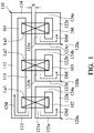
- FIG. 1 is a schematic side view of a three-phase integrated reactor in accordance with a first embodiment of the present invention.
- the three-phase integrated reactor includes a first magnetic-core frame 110, three second magnetic-core frames 120a-120c, and three coil windings La1-La3.
- the first magnetic-core frame 110 provides the common-mode effect
- the second magnetic-core frames 120a-120c provide the differential-mode effect (respectively numbered as CM and DM with arrow index).
- Each of the first magnetic-core frame 110 and the second magnetic-core frames 120a-120c may have a close-looped magnetic circuit with any suitable shape, and each includes a window (such as the window 101, 102, 103 , 104 shown in FIG. 1 ).
- each of the first magnetic-core frame 110 and the second magnetic-core frames 120a-120c shown in FIG. 1 is having a rectangular shape, this is only an example of the present invention and it is not limited thereto.
- the windows 101-104 penetrates through the first magnetic-core frame 110 and the second magnetic-core frames 120a-120c from the side shown in FIG. 1 to the opposite side, respectively, so that the coil windings La1-La3 can wind around the magnetic-core frames 110, 120a-120c through the windows 101-104, respectively.
- the first magnetic-core frame 110 is formed of a first side pillar 111 and a second side pillar 112 opposite to each other, and a third side pillar 113 and a fourth side pillar 114 opposite to each other.
- the second magnetic-core frames 120a-120c are respectively composed of corresponding first side pillars 121a-121c and second side pillars 122a-122c opposite each other, and third side pillars 123a-123c and fourth side pillars 124a-124c opposite each other.
- the second magnetic-core frames 120a-120c are all provided on a side of the first side pillar 111 of the first magnetic-core frame 110, and arranged in parallel with the axis of the first side pillar 111 of the first magnetic-core frame 110, which makes the first side pillars 121a-121c of the second magnetic-core frames 120a-120c are adjacent to the first side pillar 111 of the first magnetic-core frame 110, respectively.
- the first magnetic-core frame 110 and each of the second magnetic-core frames 120a-120c are all spaced apart from each other by a distance S to form an air gap.
- the distance S of each space is the same, but this is only an example of the present invention, and it is not limited thereto.
- the coil winding La1 winds around the first side pillar 111 of the first magnetic-core frame 110 and the first side pillar 121a of the second magnetic-core frame 120a through the window 101 and the window 102.
- the coil winding La2 winds around the first side pillar 111 of the first magnetic-core frame 110 and the first side pillar 121b of the second magnetic-core frame 120b through the window 101 and the window 103.
- the coil winding La3 winds around the first side pillar 111 of the first magnetic-core frame 110 and the first side pillar 121c of the second magnetic-core frame 120c through the window 101 and the window 104.
- the winding directions of the coil windings La1-La3 are the same.
- the first magnetic-core frame 110 and the second magnetic-core frames 120a-120c can be made of the same material.
- the first magnetic-core frame 110 and the second magnetic-core frames 120a-120c can be made of a silicon steel sheet or iron powder core.
- the first magnetic-core frame 110 which having a common-mode effect can be made of manganese zinc (MnZn) or ferrite to enhance the suppression of EMI at high frequencies
- each of the second magnetic-core frames 120a-120c is made of a silicon steel sheet or iron powder core to lower the cost of production.
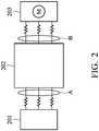
- FIG. 2 is a schematic diagram of the structure of a general converter system.
- the three-phase integrated reactor shown in FIG. 1 can be connected in series between a three-phase grid 201 and an inverter 202 (at the portion "A" shown in left part) which is shown in left part of FIG. 2 to filter the common-mode noise and the differential-mode noise generated by the three-phase grid 201.
- FIG. 3 is a schematic side view of a three-phase integrated reactor in accordance with a second embodiment of the present invention.
- the three-phase integrated reactor includes a first magnetic-core frame 310, three second magnetic-core frames 320a-320c, a third magnetic-core frame 330, three first coil windings La1-La3, and three second coil windings Lb1-Lb3.
- the first magnetic-core frame 310 and the third magnetic-core frame 330 are used to provide the common-mode effect while the second magnetic-core frames 320a-320c are used to provide the differential-mode effect (respectively numbered as CM and DM with arrow index).
- Each of the first magnetic-core frame 310, the second magnetic-core frames 320a-320c, and the third magnetic-core frame 330 has a close-looped magnetic circuit with any suitable shape, and each includes a window, respectively (windows 301, 302, 303, 304, and 305 shown in the figure). It should be noted that although each of the first magnetic-core frame 310, the second magnetic-core frames 320a-320c, and the third magnetic-core frame 330 is having a rectangular shape, but this is only an example of the present invention, and it is not limited thereto.
- the windows 301-305 go through the first magnetic-core frame 310, the second magnetic-core frames 320a-320c, and the third magnetic-core frame 330, respectively, from the side shown in the figure to another side, so that the coil windings La1-La3, Lb1-Lb3 can wind around the magnetic-core frames 310, 320a-320c, 330 through the windows 301-305, respectively.
- the first magnetic-core frame 310 is composed of a first side pillar 311 and a second side pillar 312 opposite to each other, and a third side pillar 313 and a fourth side pillar 314 opposite to each other.
- Each of the second magnetic-core frames 320a-320c is composed of corresponding first side pillars 321a-321c and second side pillars 322a-322c opposite to each other, and third side pillars 323a-323c and fourth side pillars 324a-324c opposite to each other, respectively.
- the second magnetic-core frames 320a-320c are all arranged on a first side of the first side pillar 311 of the first magnetic-core frame 310, and arranged in parallel with the axis of the first side pillar 311 of the first magnetic-core frame 310, so that the first side pillars 321a-321c of the second magnetic-core frames 320a-320c are adjacent to the first side pillar 311 of the first magnetic-core frame 310, respectively.
- the third magnetic-core frame 330 is composed of a first side pillar 331 and a second side pillar 332 opposite to each other, and a third side pillar 333 and a fourth side pillar 334 opposite to each other.
- the third magnetic-core frame 330 is arranged on a second side of each of the second side pillars 322a-322c of the second magnetic-core frames 320a-320c, so that the first side pillar 331 of the third magnetic-core frame 330 is adjacent to the second side pillars 322a-322c of the second magnetic-core frames 320a-320c, respectively.
- the first magnetic-core frame 310 and each of the second magnetic-core frames 320a-320c are respectively spaced apart from each other by a distance S1 to form air gaps
- the third magnetic-core frame 330 and each of the second magnetic-core frames 320a-320c are respectively spaced apart from each other by a distance S2 to form air gaps.
- the distances S1 and S2 are the same, but this is only an example of the present invention, and it is not limited thereto.
- Each of the first coil windings La1-La3 winds around the first side pillar 311 of the first magnetic-core frame 310 and the corresponding second side pillars 321a-321c of the second magnetic-core frames 320a-320c, respectively.
- the first coil winding La1 winds around the first side pillar 311 of the first magnetic-core frame 310 and the first side pillar 321a of the second magnetic-core frame 320a through the window 301 and the window 302.
- the first coil winding La2 winds around the first side pillar 311 of the first magnetic-core frame 310 and the first side pillar 321b of the second magnetic-core frame 320b through the window 301 and the window 303.
- the first coil winding La3 winds around the first side pillar 311 of the first magnetic-core frame 310 and the first side pillar 321c of the second magnetic-core frame 320c through the window 301 and the window 304.
- the winding directions of the first coil windings La1-La3 are the same.
- each of the second coil windings Lb1-Lb3 winds around the corresponding second side pillars 322a to 322c of the second magnetic-core frames 320a-320c and the first side pillar 331 of the third magnetic-core frame 330.
- the second coil winding Lb1 winds around the first side pillar 331 of the third magnetic-core frame 330 and the second side pillar 322a of the second magnetic-core frame 320a through the window 305 and the window 302.
- the second coil winding Lb2 winds around the first side pillar 331 of the third magnetic-core frame 330 and the second side pillar 322b of the second magnetic-core frame 320b through the window 305 and the window 303.
- the second coil winding Lb3 winds around the first side pillar 331 of the third magnetic-core frame 330 and the second side pillar 322c of the second magnetic-core frame 320c through the window 305 and the window 304.
- the winding directions of the second coil windings Lb1-Lb3 are the same, but are opposite to the winding directions of the first coil windings La1-La3.
- the first magnetic-core frame 310, the second magnetic-core frames 320a-320c, and the third magnetic-core frame 330 can be made of the same material.
- the first magnetic-core frame 310, the second magnetic-core frames 320a-320c, and the third magnetic-core frame 330 can be made of the silicon steel sheet or the iron powder core.
- the first magnetic-core frame 310 and the third magnetic-core frame 330 which having the common-mode effect can be made of manganese zinc or a ferrite material to enhance the suppression of the EMI at high frequencies, and each of the second magnetic-core frames 320a-320c is made of a silicon steel sheet or an iron powder core to lower the cost of production.
- the three-phase integrated reactor described in the second embodiment provides two sets of inductors, in one example, the three-phase integrated reactor can be connected in series with a set of capacitors and a LCL circuit.
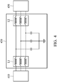
- FIG. 4 is a schematic diagram of a circuit architecture having the LCL circuit.
- the LCL circuit 420 which in combination with a three-phase integrated reactor and a set of capacitors can be connected in series between a three-phase grid 410 and an input terminal of a device 430.
- the device 430 can be an active front end (AFE) circuit, a REG circuit, an APF circuit, or an SVG circuit.
- AFE active front end
- the architecture of the LCL circuit recited in the second embodiment of the present invention has both the effect of common-mode and differential-mode at the same time, which can smooth the suddenly-increased current and raise the amount of high-frequency noise suppression.
- FIGs. 5A and 5B are schematic side views of an integrated three-phase current sensor common-mode choke with different air gaps in accordance with a third embodiment of the present invention.
- the output terminal of a general VFD system has a set of Hall sensor modules for detecting variation of the current.
- the integrated three-phase current sensor common-mode choke described below achieves the effect of suppressing the common-mode and also provides the function of current detection.
- the integrated three-phase current sensor common-mode choke includes a magnetic-core frame 510, three C-type magnetic cores 520a-520c, and three coil windings La1-La3.
- the first magnetic-core frame 510 provides the common-mode effect while the C-type magnetic cores 520a-520c provide the differential-mode effect and current detection functions (respectively numbered as CM and DM with arrow index).
- the magnetic-core frame 510 can be a close-looped magnetic circuit with any suitable shape, and it includes a window 501. It should be noted that although the magnetic-core frame 510 shown in FIG. 5A is having a rectangular shape, this is only an example of the present invention and it is not limited thereto.
- Each of the C-type magnetic cores 520a-520c is presented as a C-shaped element and respectively includes a relative larger window 502-504 therein, and a relative smaller gap 550a-550c on the opposite sides of first side pillars 521a-521c thereof.
- the windows 501-504 pass through the magnetic-core frame 510 and the C-type magnetic cores 520a-520c, respectively, from one side shown in FIG. 5A to the other side, so that the coil windings La1-La3 can wind around the magnetic-core frame 510 and the C-type magnetic cores 520a-520c through the windows 501-504, respectively.
- the magnetic-core frame 510 includes a first side pillar 511 and a second side pillar 512 opposite to each other, and a third side pillar 513 and a fourth side pillar 514 opposite to each other.
- the C-type magnetic cores 520a-520c are all arranged on a side corresponding to the first side pillar 511 of the magnetic-core frame 510, and are arranged in parallel with the axis of the first side pillar 511 of the magnetic-core frame 510, so that the first side pillars 521a-521c of the C-type magnetic cores 520a-520c are adjacent to the first side pillar 511 of the magnetic-core frame 510, respectively.
- the magnetic-core frame 510 and each of the C-type magnetic cores 520a-520c are spaced apart from each other by a distance S to form air gaps.
- the distances S are the same, but these are only examples of the present invention and it is not limited thereto.
- the magnetic-core frame 510 and the C-type magnetic cores 520a-520c can be integrated into a one-piece structure by processes or other means, which means that a magnetic-core frame and C-type magnetic cores can be formed into a structure without air gaps.
- Hall sensors 570a-570c are provided in each of the corresponding smaller gaps 550a-550c of the C-type magnetic cores 520a-520c respectively for sensing the magnetic field variations of the corresponding C-type magnetic cores 520a-520c.
- each of the coil windings La1-La3 respectively winds around the first side pillar 511 of the magnetic-core frame 510 and the corresponding first side pillars 521a-521c of the C-type magnetic cores 520a-520c.
- the coil winding La1 winds around the first side pillar 511 of the magnetic-core frame 510 and the first side pillar 521a of the C-type magnetic core 520a through the window 501 and the window 502.
- the coil winding La2 winds around the first side pillar 511 of the magnetic-core frame 510 and the first side pillar 521b of the C-type magnetic core 520b through the window 501 and the window 503.
- the coil winding La3 winds around the first side pillar 511 of the magnetic-core frame 510 and the first side pillar 521c of the C-type magnetic core 520c through the window 501 and the window 504.
- the winding directions of the coil windings La1-La3 are the same.
- the integrated three-phase current sensor common-mode choke described in the third embodiment can be adapted and connected in series between the output terminal of the VFD 202 and the motor 203 (such as the portion "B" shown in right part of FIG. 2 ) for detecting the current that drives the motor 203, and determining the switching period of the switch.
- the integrated three-phase current sensor common-mode choke system recited in this embodiment can be also adapted to filter noise between the VFD 202 and the motor 203.
- FIGs. 6A and 6B are schematic side views of a two-phase integrated reactor having different air gaps in accordance with a fourth embodiment of the present invention.
- the two-phase integrated reactor includes a magnetic-core frame 610, a first C-type magnetic core 620, a second C-type magnetic core 630, a first coil winding La, and a second coil winding Lb.
- the magnetic-core frame 610 provides the common-mode effect, and the first C-type magnetic core 620 and the second C-type magnetic core 630 provide the differential-mode effect (respectively numbered as CM and DM with arrow index).
- the magnetic-core frame 610 can be a close-looped magnetic circuit with any suitable shape, and it includes a window 601.
- each of the first C-type magnetic core 620 and the second C-type magnetic core 630 is a C-shaped element.
- the first C-type magnetic core 620 includes a relative larger window 602 and a relative smaller gap 625 located at the side corresponding to the first side pillar 621 of itself.
- the second C-type magnetic core 630 includes a relative larger window 603 and a relative smaller gap 635 located at the side corresponding to the first side pillar 631 of itself.
- the windows 601-603 respectively passes through the magnetic-core frame 610, the first C-type magnetic core 620, and the second C-type magnetic core 630 from a side shown in FIG. 6A to another side, so that the coil windings La, Lb can wind around the magnetic-core frame 610, the first C-type magnetic core 620 and the second C-type magnetic core 630 through the windows 601-603, respectively.
- the magnetic-core frame 610 includes a first side pillar 611 and a second side pillar 612 opposite to each other, and a third side pillar 613 and a fourth side pillar 614 opposite to each other.
- the first C-type magnetic core 620 is disposed on a side corresponding to the first side pillar 611 of the magnetic-core frame 610, so that the first side pillar 621 of the first C-type magnetic core 620 is adjacent to the first side pillar 611 of the magnetic-core frame 610.
- the gap 625 of the first C-type magnetic core 620 is located at a side that is far away from the first side pillar 611 of the magnetic-core frame 610.
- the second C-type magnetic core 630 is disposed on a side corresponding to the second side pillar 612 of the magnetic-core frame 610, so that the first side pillar 631 of the second C-type magnetic core 630 is adjacent to the second side pillar 612 of the magnetic-core frame 610.
- the gap 635 of the second C-type magnetic core 630 is located at a side that is far away from the second side pillar 612 of the magnetic-core frame 610.
- the magnetic-core frame 610, the first C-type magnetic core 620, and the second C-type magnetic core 630 are spaced apart from each other by a distance S1 and S2 to form air gaps, respectively.
- the distances S1 and S2 are the same, but this is only an example of the present invention and it is not limited thereto.
- the coil winding La connects to one of the P and N input terminals, and winds around the first side pillar 611 of the magnetic-core frame 610 and the first side pillar 621 of the first C-type magnetic core 620 through the window 601 and the window 602, respectively.
- the coil winding Lb connects to the other of the P and N input terminals, and winds around the second side pillar 612 of the magnetic-core frame 610 and the first side pillar 631 of the second C-type magnetic core 630 through the window 601 and the window 603, respectively.
- the winding directions of the coil windings La and Lb are the same.
- the magnetic-core frame 610, the first C-type magnetic core 620, and the second C-type magnetic core 630 can be made of the same material, for example, they can be made of silicon steel sheets or iron powder cores.
- the magnetic-core frame 610, the first C-type magnetic core 620, and the second C-type magnetic core 630 are made of the same material, it can be shown as the architecture shown in Fig 6B .
- the magnetic-core frame 610, the first C-type magnetic core 620, and the second C-type magnetic core 630 can be integrated into a one-piece structure, but it is not limited thereto.
- the magnetic-core frame 610 having the common-mode effect can be made of manganese zinc or ferrite to increase EMI suppression at high frequencies.
- the first C-type magnetic core 620 and the second C-type magnetic core 630 can be made of a silicon steel sheet or iron powder core to lower the cost of production.
- the two-phase integrated reactor can be adapted as a reactor for the DC link PN input terminal in an inverter.
- FIG. 7 is a schematic diagram of the structure of a general VFD system. As shown in FIG. 7 , the two-phase integrated reactor 730 described in the fourth embodiment is connected in series between a rectifier 720 and an inverter 740, and the system may further include a three-phase grid 710 located at the front end and a motor 750 at the rear end respectively.
- the two-phase integrated reactor of the present invention significantly increases the inductance of the common-mode at the high frequency.
- the two-phase integrated reactor can also be applied to the REG circuit to block the circular current that flows back to the three-phase grid.
- the PN current might be unbalanced due to the erroneous operation during the transformer is operated, which might cause a ground fault in the machine or system. Therefore, in order to detect the abnormal situation of PN current as soon as possible, a coil winding can be added to the magnetic-core frame 610 of the two-phase integrated reactor described in the fourth embodiment to detect the current at the PN terminal.
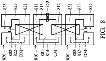
- FIG. 8 is a schematic side view of a two-phase integrated reactor having a ground fault detection function in accordance with a fifth embodiment of the present invention.
- the structure of the magnetic-core frame 810, the first C-type magnetic core 820, the second C-type magnetic core 830, the first coil winding La, and the second coil winding Lb shown in Fig. 8 are substantially the same as the two-phase integrated reactor shown in FIG. 6A , thus it is not described herein to simplify the description.
- An additional coil winding 850 is added at the third side pillar 813 of the magnetic-core frame 810 to sense the current at the PN terminal.
- the coil winding 850 is further connected to a controller (not shown), but it is not applied with the current, and is only used for sensing the current. The sensed current signal will be transmitted to the controller to execute the preventive process.
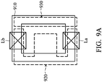
- FIG. 9A is a schematic side view of an enhanced differential-mode and common-mode reactor in accordance with a sixth embodiment of the present invention.
- FIG. 9B is a schematic side view of a magnetic-core frame of the enhanced differential-mode and common-mode reactor in accordance with the sixth embodiment of the present invention.
- FIG. 9C is a schematic side view of a core module of the enhanced differential-mode and common-mode reactor in accordance with the sixth embodiment of the present invention.
- the enhanced differential-mode common-mode reactor includes a magnetic-core frame 910, a core module, a first coil winding La, and a second coil winding Lb.
- the magnetic-core frame 910 and the core modules are stacked together vertically, which means that the magnetic-core frame 910 overlaps the core module in a projection direction.
- the magnetic-core frame 910 is used to provide the common-mode effect (numbered as CM with arrow index shown in FIG. 9B ) and the core module provides the differential-mode effect (numbered as DM with arrow index shown in FIG. 9C ), and the differential-mode current shown in the dotted line is drawn back from the center pillar of the core module to the side pillar of the core module.
- the structure of the core module will be described in detail later.
- the magnetic-core frame 910 can be a close-looped magnetic circuit with any suitable shape, and it includes a window 901.
- the magnetic-core frame 910 includes a first side pillar 911 and a second side pillar 912 opposite to each other, and a third side pillar 913 and a fourth side pillar 914 opposite to each other.
- FIG. 9B is having a rectangular shape, but this is only an example of the present invention and it is not limited thereto.
- the core module includes an E-type magnetic core 920 and an I-type magnetic core 930.
- the E-type magnetic core 920 includes a first side pillar 921, a second side pillar 922, a center pillar 923, and a third side pillar 924.
- the first side pillar 921, the second side pillar 922, and the center pillar 923 are substantially parallel to each other, and the first side pillar 921 and the second side pillar 922 are located at opposite sides of the center pillar 923, respectively.
- the first side pillar 921, the second side pillar 922, and the center pillar 923 are all perpendicular to the third side pillar 924.
- the I-type magnetic core 930 is provided on a side corresponding to the third side pillar 924 of the E-type magnetic core 920, and the first side pillar 921 and the second side pillar 922 of the E-type magnetic core 920 and the I-type magnetic core 930 are spaced apart from each other by a distance S1 to form air gaps, respectively, in order to facilitate the adjustment of the magnetic properties.
- the distances S1 between the first side pillar 921 or the second side pillar 922 of the E-type magnetic core 920 and the I-type magnetic core 930 are the same, and the distances S1 can be adjusted based on the configuration of the I-type magnetic core 930 and the E-type magnetic core 920, that is, the air gaps between the I-type magnetic core 930 and the E-type magnetic core 920 can be adjusted.
- the center pillar 923 of the E-type magnetic core 920 is shorter than both the first side pillar 921 and the second side pillar 922 of the E-type magnetic core 920 (as shown in FIG. 9C , the distance S1 is smaller than the distance S2), but this is only an example of the present invention and it is not limited thereto.
- the coil winding La winds around the first side pillar 911 of the magnetic-core frame 910 and the first side pillar 921 of the E-type magnetic core 920 through the window 901 of the magnetic-core frame 910.
- the coil winding Lb winds around the second side pillar 912 of the magnetic-core frame 910 and the second side pillar 922 of the E-type magnetic core 920 through the window 901 of the magnetic-core frame 910.
- the winding directions of the coil windings La and Lb are the same.
- the magnetic-core frame 910 and the core module can be made of the same material, for example, they can be made of the silicon steel sheets or the iron powder cores.
- the magnetic-core frame 910 in order to provide a better common-mode effect, can also be made of the manganese zinc or the ferrite, and the core module is made of the silicon steel sheets or the iron powder core to enhance the high-frequency common-mode effect and to lower the production costs.
- the various integrated magnetic elements of embodiments of the present invention it is possible to achieve the effects of suppressing the common-mode noise and the differential-mode noise at the same time without placing an extra capacitor for increasing the EMI suppression effect in the VFD system, which can avoid the sides effects that the capacitor might generate a large leakage current or high voltage noise will be entered into the capacitor.
- the design of the system design can be simplified to reduce the size and the costs of the system or the device.
Landscapes
- Engineering & Computer Science (AREA)
- Power Engineering (AREA)
- Chemical & Material Sciences (AREA)
- Composite Materials (AREA)
- Microelectronics & Electronic Packaging (AREA)
- Coils Or Transformers For Communication (AREA)
- Inverter Devices (AREA)
Applications Claiming Priority (1)
| Application Number | Priority Date | Filing Date | Title |
|---|---|---|---|
| CN201710963855.8A CN109671552B (zh) | 2017-10-17 | 2017-10-17 | 整合型磁性元件 |
Publications (3)
| Publication Number | Publication Date |
|---|---|
| EP3483901A2 true EP3483901A2 (de) | 2019-05-15 |
| EP3483901A3 EP3483901A3 (de) | 2019-06-26 |
| EP3483901B1 EP3483901B1 (de) | 2020-09-09 |
Family
ID=63173936
Family Applications (1)
| Application Number | Title | Priority Date | Filing Date |
|---|---|---|---|
| EP18185468.8A Active EP3483901B1 (de) | 2017-10-17 | 2018-07-25 | Integrierte magnetelemente |
Country Status (3)
| Country | Link |
|---|---|
| US (2) | US10804024B2 (de) |
| EP (1) | EP3483901B1 (de) |
| CN (2) | CN109671552B (de) |
Cited By (1)
| Publication number | Priority date | Publication date | Assignee | Title |
|---|---|---|---|---|
| WO2025202092A1 (de) * | 2024-03-28 | 2025-10-02 | Tdk Electronics Ag | Induktives bauteil, magnetische kernstruktur und verfahren zur herstellung eines induktiven bauteils |
Families Citing this family (2)
| Publication number | Priority date | Publication date | Assignee | Title |
|---|---|---|---|---|
| CN111430139B (zh) * | 2020-05-12 | 2024-05-24 | 天津职业技术师范大学(中国职业培训指导教师进修中心) | 一种有效集成安装的电感阵列结构及实现方法 |
| EP4388564A4 (de) * | 2022-01-05 | 2025-06-18 | Telefonaktiebolaget LM Ericsson (publ) | Induktor zur unterdrückung von gleichtakt (cm) und differenzmodus (dm)-rauschen |
Family Cites Families (28)
| Publication number | Priority date | Publication date | Assignee | Title |
|---|---|---|---|---|
| US2792556A (en) * | 1953-08-20 | 1957-05-14 | Westinghouse Electric Corp | Ballast |
| BE634771A (de) * | 1963-06-29 | |||
| US4019123A (en) * | 1973-09-18 | 1977-04-19 | Westinghouse Brake And Signal Co. Ltd. | Magnetic amplifier arrangements |
| US4019122A (en) * | 1974-08-14 | 1977-04-19 | Telcon-Magnetic Cores Limited | Stabilized power supplies |
| CA1095601A (en) * | 1978-08-28 | 1981-02-10 | Alfred M. Hase | Regulating transformer with magnetic shunt |
| US4802055A (en) * | 1987-10-26 | 1989-01-31 | Joseph L. Brooks Manufacturing Corp. | Transient voltage surge suppressor |
| CH676763A5 (de) * | 1988-01-14 | 1991-02-28 | Susanne Riedi Joks | |
| JPH0779063B2 (ja) * | 1988-08-15 | 1995-08-23 | 三菱電機株式会社 | 位相調整変圧器 |
| US5163173A (en) * | 1991-03-29 | 1992-11-10 | Top Gulf Coast Corporation | Variable impedance transformer with equalizing winding |
| US5789907A (en) * | 1991-03-29 | 1998-08-04 | Top Gulf Coast Corporation | Variable impedence transformer |
| US5376912A (en) * | 1992-03-12 | 1994-12-27 | Casagrande; Serge | Combined transformer and inductor |
| US6400249B1 (en) * | 2000-12-18 | 2002-06-04 | Ascom Energy Systems Ag | Transformer providing low output voltage |
| US7142081B1 (en) * | 2005-05-03 | 2006-11-28 | Mte Corporation | Multiple three-phase inductor with a common core |
| TWI358187B (en) * | 2007-08-16 | 2012-02-11 | Delta Electronics Inc | Magnetic integrated circuit for multiphase interle |
| US20090167473A1 (en) * | 2007-12-27 | 2009-07-02 | Wen-Sen Hsieh | Transformer structure |
| EP2299456B1 (de) * | 2009-09-17 | 2016-08-24 | DET International Holding Limited | Integriertes magnetisches Bauteil |
| JP5391168B2 (ja) | 2010-09-03 | 2014-01-15 | 本田技研工業株式会社 | 複合型変圧器 |
| US8692644B2 (en) * | 2011-01-24 | 2014-04-08 | Mte Corporation | Harmonic mitigation devices and applications thereof |
| US8791782B2 (en) * | 2011-01-28 | 2014-07-29 | Uses, Inc. | AC power conditioning circuit |
| CN103578691B (zh) * | 2012-07-26 | 2016-08-17 | 浙江海利普电子科技有限公司 | 扼流圈和emi滤波电路 |
| JP5790700B2 (ja) * | 2013-04-15 | 2015-10-07 | 株式会社デンソー | フィルタ部品 |
| DE102014206469A1 (de) * | 2014-04-03 | 2015-10-08 | SUMIDA Components & Modules GmbH | Drossel und drosselkern |
| JP6504778B2 (ja) * | 2014-10-08 | 2019-04-24 | 住友重機械工業株式会社 | コンバータおよびそれを用いた作業機械 |
| CN106158243B (zh) * | 2015-04-10 | 2018-11-20 | 台达电子工业股份有限公司 | 电源转换器及其集成式电感装置 |
| CN204808997U (zh) * | 2015-07-09 | 2015-11-25 | 台达电子企业管理(上海)有限公司 | 磁性组件及其适用的电源系统 |
| CN106340880B (zh) * | 2016-11-30 | 2018-01-05 | 广东电网有限责任公司茂名供电局 | 铁芯结构改变的配电网中性线零序谐波抑制装置 |
| CN106504855B (zh) * | 2016-12-30 | 2018-06-12 | 上海意兰可电力电子设备有限公司 | 三相电抗器内置共模电抗器 |
| EP3699936B1 (de) * | 2017-01-12 | 2025-10-29 | Delta Electronics (Thailand) Public Co., Ltd. | Integriertes magnetisches bauteil und schaltstromwandler |
-
2017
- 2017-10-17 CN CN201710963855.8A patent/CN109671552B/zh active Active
- 2017-10-17 CN CN202110259726.7A patent/CN113113206B/zh active Active
-
2018
- 2018-05-31 US US15/994,007 patent/US10804024B2/en active Active
- 2018-07-25 EP EP18185468.8A patent/EP3483901B1/de active Active
-
2020
- 2020-09-14 US US17/020,388 patent/US11605489B2/en active Active
Non-Patent Citations (1)
| Title |
|---|
| None |
Cited By (1)
| Publication number | Priority date | Publication date | Assignee | Title |
|---|---|---|---|---|
| WO2025202092A1 (de) * | 2024-03-28 | 2025-10-02 | Tdk Electronics Ag | Induktives bauteil, magnetische kernstruktur und verfahren zur herstellung eines induktiven bauteils |
Also Published As
| Publication number | Publication date |
|---|---|
| EP3483901B1 (de) | 2020-09-09 |
| CN113113206A (zh) | 2021-07-13 |
| US11605489B2 (en) | 2023-03-14 |
| EP3483901A3 (de) | 2019-06-26 |
| US10804024B2 (en) | 2020-10-13 |
| CN113113206B (zh) | 2022-10-18 |
| US20190115139A1 (en) | 2019-04-18 |
| CN109671552B (zh) | 2021-04-09 |
| US20200411225A1 (en) | 2020-12-31 |
| CN109671552A (zh) | 2019-04-23 |
Similar Documents
| Publication | Publication Date | Title |
|---|---|---|
| US11062837B2 (en) | Planar transformer, power conversion circuit, and adapter | |
| US11605489B2 (en) | Integrated magnetic elements | |
| US8670250B2 (en) | Common mode noise reduction apparatus and method | |
| WO2017211104A1 (zh) | Emi滤波器及电源emi滤波器接入电路 | |
| US20130049918A1 (en) | Common Mode Choke Apparatus and Method | |
| JP6568743B2 (ja) | 伝導性ノイズ抑制回路及びインバータ装置 | |
| US20130308352A1 (en) | Method for improving performance of filter and power conversion apparatus | |
| US8994305B2 (en) | Filtering reactor stage and variable-frequency driving system using the same | |
| CN112152444A (zh) | 功率因数校正电路、电路板及空调器 | |
| CN101610027B (zh) | 一种功率因数校正用电磁干扰抑制电路 | |
| CN210629360U (zh) | 基于差共模一体电抗器的变频装置 | |
| US20220108823A1 (en) | Inductor | |
| Jiang et al. | Terminal configuration principles for achieving various electromagnetic integration units with flexible multilayer foil technique | |
| US20210194348A1 (en) | Common mode (cm) electromagnetic interference (emi) filters for reducing radiated emi in power converters | |
| KR20130006019U (ko) | 씨엠/디엠 일체형 이엠아이필터 | |
| CN102403957A (zh) | 一种无谐波变频调速装置 | |
| CN105261461A (zh) | 抵抗共模干扰的变压器绕线电路、结构及便携式充电器 | |
| CN213340022U (zh) | 一种变压器装置、开关电源和电源适配器 | |
| CN213185875U (zh) | 功率因数校正电路、电路板及空调器 | |
| KR20150091730A (ko) | 누설자속저감 권선법을 이용한 공진형 전력변환기용 변압기 | |
| CN110581011A (zh) | 集成式emc滤波器和电力电子装置 | |
| CN110601516A (zh) | 一种滤波装置、电源及其滤波方法 | |
| CN214624709U (zh) | 一种医用设备供电系统用滤波电抗器 | |
| CN210429514U (zh) | 去y电容的变压器 | |
| He et al. | Analysis and Design of EMI Filter Based on Differential Mode Inductor Magnetic Integration |
Legal Events
| Date | Code | Title | Description |
|---|---|---|---|
| PUAI | Public reference made under article 153(3) epc to a published international application that has entered the european phase |
Free format text: ORIGINAL CODE: 0009012 |
|
| STAA | Information on the status of an ep patent application or granted ep patent |
Free format text: STATUS: THE APPLICATION HAS BEEN PUBLISHED |
|
| AK | Designated contracting states |
Kind code of ref document: A2 Designated state(s): AL AT BE BG CH CY CZ DE DK EE ES FI FR GB GR HR HU IE IS IT LI LT LU LV MC MK MT NL NO PL PT RO RS SE SI SK SM TR |
|
| AX | Request for extension of the european patent |
Extension state: BA ME |
|
| PUAL | Search report despatched |
Free format text: ORIGINAL CODE: 0009013 |
|
| AK | Designated contracting states |
Kind code of ref document: A3 Designated state(s): AL AT BE BG CH CY CZ DE DK EE ES FI FR GB GR HR HU IE IS IT LI LT LU LV MC MK MT NL NO PL PT RO RS SE SI SK SM TR |
|
| AX | Request for extension of the european patent |
Extension state: BA ME |
|
| RIC1 | Information provided on ipc code assigned before grant |
Ipc: H01F 38/00 20060101ALN20190517BHEP Ipc: H01F 3/10 20060101AFI20190517BHEP Ipc: H01F 27/38 20060101ALI20190517BHEP |
|
| STAA | Information on the status of an ep patent application or granted ep patent |
Free format text: STATUS: REQUEST FOR EXAMINATION WAS MADE |
|
| 17P | Request for examination filed |
Effective date: 20191220 |
|
| RBV | Designated contracting states (corrected) |
Designated state(s): AL AT BE BG CH CY CZ DE DK EE ES FI FR GB GR HR HU IE IS IT LI LT LU LV MC MK MT NL NO PL PT RO RS SE SI SK SM TR |
|
| RIC1 | Information provided on ipc code assigned before grant |
Ipc: H01F 3/10 20060101AFI20200213BHEP Ipc: H01F 27/38 20060101ALI20200213BHEP Ipc: H01F 38/00 20060101ALN20200213BHEP |
|
| GRAP | Despatch of communication of intention to grant a patent |
Free format text: ORIGINAL CODE: EPIDOSNIGR1 |
|
| STAA | Information on the status of an ep patent application or granted ep patent |
Free format text: STATUS: GRANT OF PATENT IS INTENDED |
|
| RIC1 | Information provided on ipc code assigned before grant |
Ipc: H01F 27/38 20060101ALI20200306BHEP Ipc: H01F 38/00 20060101ALN20200306BHEP Ipc: H01F 3/10 20060101AFI20200306BHEP |
|
| INTG | Intention to grant announced |
Effective date: 20200323 |
|
| GRAS | Grant fee paid |
Free format text: ORIGINAL CODE: EPIDOSNIGR3 |
|
| GRAA | (expected) grant |
Free format text: ORIGINAL CODE: 0009210 |
|
| STAA | Information on the status of an ep patent application or granted ep patent |
Free format text: STATUS: THE PATENT HAS BEEN GRANTED |
|
| AK | Designated contracting states |
Kind code of ref document: B1 Designated state(s): AL AT BE BG CH CY CZ DE DK EE ES FI FR GB GR HR HU IE IS IT LI LT LU LV MC MK MT NL NO PL PT RO RS SE SI SK SM TR |
|
| REG | Reference to a national code |
Ref country code: GB Ref legal event code: FG4D |
|
| REG | Reference to a national code |
Ref country code: AT Ref legal event code: REF Ref document number: 1312609 Country of ref document: AT Kind code of ref document: T Effective date: 20200915 Ref country code: CH Ref legal event code: EP |
|
| REG | Reference to a national code |
Ref country code: IE Ref legal event code: FG4D |
|
| REG | Reference to a national code |
Ref country code: DE Ref legal event code: R096 Ref document number: 602018007562 Country of ref document: DE |
|
| REG | Reference to a national code |
Ref country code: FI Ref legal event code: FGE |
|
| REG | Reference to a national code |
Ref country code: LT Ref legal event code: MG4D |
|
| PG25 | Lapsed in a contracting state [announced via postgrant information from national office to epo] |
Ref country code: SE Free format text: LAPSE BECAUSE OF FAILURE TO SUBMIT A TRANSLATION OF THE DESCRIPTION OR TO PAY THE FEE WITHIN THE PRESCRIBED TIME-LIMIT Effective date: 20200909 Ref country code: BG Free format text: LAPSE BECAUSE OF FAILURE TO SUBMIT A TRANSLATION OF THE DESCRIPTION OR TO PAY THE FEE WITHIN THE PRESCRIBED TIME-LIMIT Effective date: 20201209 Ref country code: NO Free format text: LAPSE BECAUSE OF FAILURE TO SUBMIT A TRANSLATION OF THE DESCRIPTION OR TO PAY THE FEE WITHIN THE PRESCRIBED TIME-LIMIT Effective date: 20201209 Ref country code: HR Free format text: LAPSE BECAUSE OF FAILURE TO SUBMIT A TRANSLATION OF THE DESCRIPTION OR TO PAY THE FEE WITHIN THE PRESCRIBED TIME-LIMIT Effective date: 20200909 Ref country code: GR Free format text: LAPSE BECAUSE OF FAILURE TO SUBMIT A TRANSLATION OF THE DESCRIPTION OR TO PAY THE FEE WITHIN THE PRESCRIBED TIME-LIMIT Effective date: 20201210 Ref country code: LT Free format text: LAPSE BECAUSE OF FAILURE TO SUBMIT A TRANSLATION OF THE DESCRIPTION OR TO PAY THE FEE WITHIN THE PRESCRIBED TIME-LIMIT Effective date: 20200909 |
|
| REG | Reference to a national code |
Ref country code: AT Ref legal event code: MK05 Ref document number: 1312609 Country of ref document: AT Kind code of ref document: T Effective date: 20200909 |
|
| REG | Reference to a national code |
Ref country code: NL Ref legal event code: MP Effective date: 20200909 |
|
| PG25 | Lapsed in a contracting state [announced via postgrant information from national office to epo] |
Ref country code: LV Free format text: LAPSE BECAUSE OF FAILURE TO SUBMIT A TRANSLATION OF THE DESCRIPTION OR TO PAY THE FEE WITHIN THE PRESCRIBED TIME-LIMIT Effective date: 20200909 Ref country code: RS Free format text: LAPSE BECAUSE OF FAILURE TO SUBMIT A TRANSLATION OF THE DESCRIPTION OR TO PAY THE FEE WITHIN THE PRESCRIBED TIME-LIMIT Effective date: 20200909 Ref country code: PL Free format text: LAPSE BECAUSE OF FAILURE TO SUBMIT A TRANSLATION OF THE DESCRIPTION OR TO PAY THE FEE WITHIN THE PRESCRIBED TIME-LIMIT Effective date: 20200909 |
|
| PG25 | Lapsed in a contracting state [announced via postgrant information from national office to epo] |
Ref country code: SM Free format text: LAPSE BECAUSE OF FAILURE TO SUBMIT A TRANSLATION OF THE DESCRIPTION OR TO PAY THE FEE WITHIN THE PRESCRIBED TIME-LIMIT Effective date: 20200909 Ref country code: EE Free format text: LAPSE BECAUSE OF FAILURE TO SUBMIT A TRANSLATION OF THE DESCRIPTION OR TO PAY THE FEE WITHIN THE PRESCRIBED TIME-LIMIT Effective date: 20200909 Ref country code: CZ Free format text: LAPSE BECAUSE OF FAILURE TO SUBMIT A TRANSLATION OF THE DESCRIPTION OR TO PAY THE FEE WITHIN THE PRESCRIBED TIME-LIMIT Effective date: 20200909 Ref country code: PT Free format text: LAPSE BECAUSE OF FAILURE TO SUBMIT A TRANSLATION OF THE DESCRIPTION OR TO PAY THE FEE WITHIN THE PRESCRIBED TIME-LIMIT Effective date: 20210111 Ref country code: RO Free format text: LAPSE BECAUSE OF FAILURE TO SUBMIT A TRANSLATION OF THE DESCRIPTION OR TO PAY THE FEE WITHIN THE PRESCRIBED TIME-LIMIT Effective date: 20200909 |
|
| PG25 | Lapsed in a contracting state [announced via postgrant information from national office to epo] |
Ref country code: AT Free format text: LAPSE BECAUSE OF FAILURE TO SUBMIT A TRANSLATION OF THE DESCRIPTION OR TO PAY THE FEE WITHIN THE PRESCRIBED TIME-LIMIT Effective date: 20200909 Ref country code: AL Free format text: LAPSE BECAUSE OF FAILURE TO SUBMIT A TRANSLATION OF THE DESCRIPTION OR TO PAY THE FEE WITHIN THE PRESCRIBED TIME-LIMIT Effective date: 20200909 Ref country code: ES Free format text: LAPSE BECAUSE OF FAILURE TO SUBMIT A TRANSLATION OF THE DESCRIPTION OR TO PAY THE FEE WITHIN THE PRESCRIBED TIME-LIMIT Effective date: 20200909 Ref country code: IS Free format text: LAPSE BECAUSE OF FAILURE TO SUBMIT A TRANSLATION OF THE DESCRIPTION OR TO PAY THE FEE WITHIN THE PRESCRIBED TIME-LIMIT Effective date: 20210109 |
|
| REG | Reference to a national code |
Ref country code: DE Ref legal event code: R097 Ref document number: 602018007562 Country of ref document: DE |
|
| PG25 | Lapsed in a contracting state [announced via postgrant information from national office to epo] |
Ref country code: SK Free format text: LAPSE BECAUSE OF FAILURE TO SUBMIT A TRANSLATION OF THE DESCRIPTION OR TO PAY THE FEE WITHIN THE PRESCRIBED TIME-LIMIT Effective date: 20200909 |
|
| PLBE | No opposition filed within time limit |
Free format text: ORIGINAL CODE: 0009261 |
|
| STAA | Information on the status of an ep patent application or granted ep patent |
Free format text: STATUS: NO OPPOSITION FILED WITHIN TIME LIMIT |
|
| 26N | No opposition filed |
Effective date: 20210610 |
|
| PG25 | Lapsed in a contracting state [announced via postgrant information from national office to epo] |
Ref country code: DK Free format text: LAPSE BECAUSE OF FAILURE TO SUBMIT A TRANSLATION OF THE DESCRIPTION OR TO PAY THE FEE WITHIN THE PRESCRIBED TIME-LIMIT Effective date: 20200909 Ref country code: SI Free format text: LAPSE BECAUSE OF FAILURE TO SUBMIT A TRANSLATION OF THE DESCRIPTION OR TO PAY THE FEE WITHIN THE PRESCRIBED TIME-LIMIT Effective date: 20200909 |
|
| PG25 | Lapsed in a contracting state [announced via postgrant information from national office to epo] |
Ref country code: IT Free format text: LAPSE BECAUSE OF FAILURE TO SUBMIT A TRANSLATION OF THE DESCRIPTION OR TO PAY THE FEE WITHIN THE PRESCRIBED TIME-LIMIT Effective date: 20200909 |
|
| REG | Reference to a national code |
Ref country code: CH Ref legal event code: PL |
|
| PG25 | Lapsed in a contracting state [announced via postgrant information from national office to epo] |
Ref country code: MC Free format text: LAPSE BECAUSE OF FAILURE TO SUBMIT A TRANSLATION OF THE DESCRIPTION OR TO PAY THE FEE WITHIN THE PRESCRIBED TIME-LIMIT Effective date: 20200909 |
|
| REG | Reference to a national code |
Ref country code: BE Ref legal event code: MM Effective date: 20210731 |
|
| PG25 | Lapsed in a contracting state [announced via postgrant information from national office to epo] |
Ref country code: LI Free format text: LAPSE BECAUSE OF NON-PAYMENT OF DUE FEES Effective date: 20210731 Ref country code: CH Free format text: LAPSE BECAUSE OF NON-PAYMENT OF DUE FEES Effective date: 20210731 |
|
| PG25 | Lapsed in a contracting state [announced via postgrant information from national office to epo] |
Ref country code: LU Free format text: LAPSE BECAUSE OF NON-PAYMENT OF DUE FEES Effective date: 20210725 Ref country code: FR Free format text: LAPSE BECAUSE OF NON-PAYMENT OF DUE FEES Effective date: 20210731 |
|
| PG25 | Lapsed in a contracting state [announced via postgrant information from national office to epo] |
Ref country code: IE Free format text: LAPSE BECAUSE OF NON-PAYMENT OF DUE FEES Effective date: 20210725 Ref country code: BE Free format text: LAPSE BECAUSE OF NON-PAYMENT OF DUE FEES Effective date: 20210731 |
|
| GBPC | Gb: european patent ceased through non-payment of renewal fee |
Effective date: 20220725 |
|
| PG25 | Lapsed in a contracting state [announced via postgrant information from national office to epo] |
Ref country code: GB Free format text: LAPSE BECAUSE OF NON-PAYMENT OF DUE FEES Effective date: 20220725 |
|
| PG25 | Lapsed in a contracting state [announced via postgrant information from national office to epo] |
Ref country code: NL Free format text: LAPSE BECAUSE OF NON-PAYMENT OF DUE FEES Effective date: 20200923 Ref country code: CY Free format text: LAPSE BECAUSE OF FAILURE TO SUBMIT A TRANSLATION OF THE DESCRIPTION OR TO PAY THE FEE WITHIN THE PRESCRIBED TIME-LIMIT Effective date: 20200909 |
|
| PG25 | Lapsed in a contracting state [announced via postgrant information from national office to epo] |
Ref country code: HU Free format text: LAPSE BECAUSE OF FAILURE TO SUBMIT A TRANSLATION OF THE DESCRIPTION OR TO PAY THE FEE WITHIN THE PRESCRIBED TIME-LIMIT; INVALID AB INITIO Effective date: 20180725 |
|
| PG25 | Lapsed in a contracting state [announced via postgrant information from national office to epo] |
Ref country code: MK Free format text: LAPSE BECAUSE OF FAILURE TO SUBMIT A TRANSLATION OF THE DESCRIPTION OR TO PAY THE FEE WITHIN THE PRESCRIBED TIME-LIMIT Effective date: 20200909 |
|
| PG25 | Lapsed in a contracting state [announced via postgrant information from national office to epo] |
Ref country code: MT Free format text: LAPSE BECAUSE OF FAILURE TO SUBMIT A TRANSLATION OF THE DESCRIPTION OR TO PAY THE FEE WITHIN THE PRESCRIBED TIME-LIMIT Effective date: 20200909 |
|
| PGFP | Annual fee paid to national office [announced via postgrant information from national office to epo] |
Ref country code: FI Payment date: 20250725 Year of fee payment: 8 |
|
| PGFP | Annual fee paid to national office [announced via postgrant information from national office to epo] |
Ref country code: DE Payment date: 20250729 Year of fee payment: 8 |
|
| PG25 | Lapsed in a contracting state [announced via postgrant information from national office to epo] |
Ref country code: TR Free format text: LAPSE BECAUSE OF FAILURE TO SUBMIT A TRANSLATION OF THE DESCRIPTION OR TO PAY THE FEE WITHIN THE PRESCRIBED TIME-LIMIT Effective date: 20200909 |