EP3483848A1 - Storage bag and paper sheet processing apparatus - Google Patents
Storage bag and paper sheet processing apparatus Download PDFInfo
- Publication number
- EP3483848A1 EP3483848A1 EP17827358.7A EP17827358A EP3483848A1 EP 3483848 A1 EP3483848 A1 EP 3483848A1 EP 17827358 A EP17827358 A EP 17827358A EP 3483848 A1 EP3483848 A1 EP 3483848A1
- Authority
- EP
- European Patent Office
- Prior art keywords
- storage bag
- banknote storage
- banknote
- opening
- banknotes
- Prior art date
- Legal status (The legal status is an assumption and is not a legal conclusion. Google has not performed a legal analysis and makes no representation as to the accuracy of the status listed.)
- Granted
Links
Images



Classifications
-
- G—PHYSICS
- G07—CHECKING-DEVICES
- G07D—HANDLING OF COINS OR VALUABLE PAPERS, e.g. TESTING, SORTING BY DENOMINATIONS, COUNTING, DISPENSING, CHANGING OR DEPOSITING
- G07D11/00—Devices accepting coins; Devices accepting, dispensing, sorting or counting valuable papers
- G07D11/10—Mechanical details
- G07D11/12—Containers for valuable papers
-
- B—PERFORMING OPERATIONS; TRANSPORTING
- B65—CONVEYING; PACKING; STORING; HANDLING THIN OR FILAMENTARY MATERIAL
- B65H—HANDLING THIN OR FILAMENTARY MATERIAL, e.g. SHEETS, WEBS, CABLES
- B65H31/00—Pile receivers
- B65H31/26—Auxiliary devices for retaining articles in the pile
-
- G—PHYSICS
- G07—CHECKING-DEVICES
- G07D—HANDLING OF COINS OR VALUABLE PAPERS, e.g. TESTING, SORTING BY DENOMINATIONS, COUNTING, DISPENSING, CHANGING OR DEPOSITING
- G07D13/00—Handling of coins or of valuable papers, characterised by a combination of mechanisms not covered by a single one of groups G07D1/00 - G07D11/00
-
- G—PHYSICS
- G07—CHECKING-DEVICES
- G07F—COIN-FREED OR LIKE APPARATUS
- G07F19/00—Complete banking systems; Coded card-freed arrangements adapted for dispensing or receiving monies or the like and posting such transactions to existing accounts, e.g. automatic teller machines
-
- E—FIXED CONSTRUCTIONS
- E05—LOCKS; KEYS; WINDOW OR DOOR FITTINGS; SAFES
- E05G—SAFES OR STRONG-ROOMS FOR VALUABLES; BANK PROTECTION DEVICES; SAFETY TRANSACTION PARTITIONS
- E05G7/00—Safety transaction partitions, e.g. movable pay-plates; Bank drive-up windows
- E05G7/001—Bank depositories
Definitions
- the present invention relates to a storage bag in which sheets such as banknotes are stored, and a sheet handling apparatus to which such a storage bag can be detachably mounted.
- banknote handling machine for performing various processes such as deposit processing and dispense processing of banknotes
- a banknote handling machine for example, one disclosed in Japanese Patent Application Laid-Open No. 2014-174581 ( JP2014-174581A ) and the like is conventionally known. More specifically, Japanese Patent Application Laid-Open No. 2014-174581 discloses a cash accounting apparatus installed in a back office area of a store such as a supermarket so that a storage bag for storing banknotes can be detachably mounted to the cash accounting apparatus and the banknotes deposited in the cash accounting apparatus are stored in the storage bag.
- the conventional storage bag has a substantially rectangular shape, and a lateral width of a side surface of the storage bag is about the same size from the opening to the bottom.
- a storage bag if such a storage bag is used, there is a problem that the banknotes stored in the storage bag in a stacked state tend to collapse. More specifically, in order to ensure that the banknotes are stored in the storage bag, it is necessary to make the opening provided at an upper end of the storage bag as large as possible, but if the size of the opening is increased, the lateral width of the storage bag also becomes large.
- the lateral width of the storage bag is much larger than the length of the banknote in the longitudinal direction, there is a possibility that the banknotes collapse inside the storage bag when a plurality of banknotes is stored in the storage bag in a stacked state.
- a storage bag of the present invention mounted to a sheet handling apparatus and configured to store sheets handled by the sheet handling apparatus includes: an upper end at which an opening is provided; and a periferal length of an internal space of the storage bag at a position where the opening is provided is the maximum size.
- a plurality of sheets may be stored in the storage bag in a stacked state.
- the periferal length of the internal space may decrease as a distance from the opening increases.
- a lateral width of a side surface of the storage bag may be the maximum size at the position where the opening is provided, and the lateral width of the side surface of the storage bag may decrease as a distance from the opening increases.
- a reinforcing unit for reinforcing a side surface of the storage bag may be provided in the vicinity of the opening, and the periferal length of the internal space at a position where the reinforcing unit is provided may be the same length.
- the storage bag may have a substantially rectangular shape, and the internal space may be formed by adhering an internal surface of a portion near an edge of the storage bag.
- the storage bag may include a first portion which is provided on a side close to the opening and the periferal length of the internal space decreases as a distance from the opening increases, and a second portion which is provided on a side farther from the opening than the first portion and having a constant periferal length of the internal space.
- a sheet handling apparatus of the present invention to which a storage bag as described above is detachably mounted includes: a pair of left and right holding members configured to hold a portion of the storage bag in the vicinity of the opening; and a platform on which at least a part of the storage bag held by the holding members is placed, the platform being movable in a substantially vertical direction, and a distance between the holding members when holding the storage bag is larger than a width of the platform.
- the sheet handling apparatus of the present invention may further include a pair of left and right regulating members configured to regulate respective sides of the storage bag held by each holding member, and the distance between the holding members when holding the storage bag is larger than a distance between the regulating members.
- each regulating member that faces the respective sides of the storage bag may be inclined with respect to a vertical direction so as to approach each other as a distance from the opening of the storage bag held by the holding members increases.
- the sheet handling apparatus of the present invention may further include: a temporary storage unit configured to temporarily hold a sheet to be stored in the storage bag held by the holding members; and a pusher for pushing the sheets held by the temporary storage unit into the inside of the storage bag held by the holding members.
- FIGS. 1 to 11 are diagrams showing a banknote handling machine according to the present embodiment and a banknote storage bag mounted to a mounting unit of such a banknote handling machine.
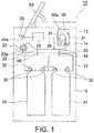
- FIG. 1 is a schematic configuration diagram schematically showing an internal configuration of the banknote handling machine according to the present embodiment
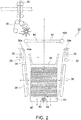
- FIG. 2 is a side view showing a detail of a configuration of a banknote storage mechanism in the banknote handling machine shown in FIG. 1
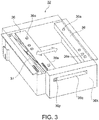
- FIG. 3 is a perspective view showing a configuration of a pair of holding members and the like in the banknote storage mechanism shown in FIG. 2 .
- FIGS. 1 to 11 are diagrams showing a banknote handling machine according to the present embodiment and a banknote storage bag mounted to a mounting unit of such a banknote handling machine.
- FIG. 1 is a schematic configuration diagram schematically showing an internal configuration of the banknote handling machine according to the present embodiment
- FIG. 2 is a side view showing a detail of a configuration of a banknote storage mechanism in the banknote handling machine shown in FIG. 1
- FIG. 4 to 9 are side views showing various examples of configurations of banknote storage bag to be held by each holding member of the banknote storage mechanism shown in FIG. 2 and the like.
- FIG. 10 is a side view showing a configuration of a conventional banknote storage bag.
- FIG. 11 is a functional block diagram showing a configuration of a control system of the banknote handling machine shown in FIG. 1 and the like.
- a banknote handling machine 10 is generally installed in a front office area or back office area of a store such as a supermarket, or placed in a lobby of a bank or an inside of the bank, and the banknote handling machine 10 can perform various processes such as deposit processing of banknotes.
- the banknote handling machine 10 has a substantially rectangular parallelepiped housing 12.
- a left side surface of the housing 12 in FIG. 1 is a front surface of the housing 12 (that is, the surface facing an operator).
- An upper assembly 14 and a lower assembly 16 are arranged inside the housing 12 such that the upper assembly 14 and the lower assembly 16 can be respectively drawn forward from the front surface of the housing 12 (specifically, to the left in FIG. 1 ).
- an inlet unit 20 such as a hopper for taking in the banknotes from outside into inside the housing 12 is disposed at an upper part of the front surface of the housing 12 (the upper part of the left side surface in FIG. 1 ). Further, in the upper assembly 14, an outlet 22 for feeding out the banknotes from inside the housing 12 to outside is disposed below the inlet unit 20 in the front surface of the housing 12 (the surface on the left side in FIG. 1 ).
- the inlet unit 20 is provided with a banknote feeding mechanism 20a for feeding the banknotes, placed on the inlet unit 20 in a stacked state by the operator, one by one into the housing 12.
- a transporting unit 24 for transporting the banknotes one by one in the housing 12 is disposed in the upper assembly 14 in the housing 12 of the banknote handling machine 10.
- the banknotes fed out from the inlet unit 20 by the banknote feeding mechanism 20a are transported one by one by the transporting unit 24.
- the transporting unit 24 is provided with a recognition unit 26. Each banknote fed out to the transporting unit 24 by the banknote feeding mechanism 20a is recognized by the recognition unit 26 for the denomination, authenticity, front/back, fitness, new/old, transportation state, and the like.
- the outlet 22 is connected to the transporting unit 24, and the banknote sent from the transporting unit 24 to the outlet 22 is stacked in the outlet 22.
- the outlet 22 is accessible from outside the housing 12 so that the operator can take out the banknotes stacked in the outlet 22 from the front surface of the housing 12.
- a stacking wheel 22a is disposed at a connection point between the transporting unit 24 and the outlet 22, and the stacking wheel 22a is adapted to rotate in a counterclockwise direction in FIG. 1 .
- the stacking wheel 22a rotates in the counterclockwise direction in FIG. 1 in a state in which the banknote is held between two blades of the stacking wheel 22a. Then, the banknote held between the two blades of the stacking wheel 22a is stacked in the outlet 22 in an aligned state.
- the transporting unit 24 is provided with a tape-type storage/feeding unit 30.
- the banknote sent from the transporting unit 24 to the storage/feeding unit 30 is stored in the storage/feeding unit 30 and the banknotes stored in the storage/feeding unit 30 can be fed out one by one to the transporting unit 24.
- the storage/feeding unit 30 is provided with a drum 30a rotatable in both forward and reverse directions, and one end of a pair of band-shaped tapes 31 is connected to an outer peripheral surface of the drum 30a.
- the banknote When the banknote is sent from the transporting unit 24 to the storage/feeding unit 30, the banknote is wound on the drum 30a by each band-shaped tape 31 such that the banknote and each tape 31 are integrally wound on the drum 30a.
- the banknote wound on the drum 30a is discharged from each tape 31 and is fed out to the transporting unit 24.
- a plurality of (for example, two) banknote storage mechanisms 32 is provided in the lower assembly 16 to store banknotes inside a banknote storage bag 34 having an opening on one side.
- Each banknote storage mechanism 32 is provided with a pair of holding members 36 which space apart from each other and face each other. Two portions of the banknote storage bag 34, facing each other in the vicinity of the opening of the banknote storage bag 34, are held by the pair of holding members 36, respectively.
- One holding member 36 (For example, the holding member 36 on the right side in FIGS. 1 and 2 ) is fixed in a fixed position and does not move from the fixed position.
- the other holding member 36 (For example, the holding member 36 on the left side in FIGS.
- each holding member 36 is provided with a heating member 38.
- the one holding member 36 moves toward the other holding member 36.
- the two holding members 36 are in contact with each other via the banknote storage bag 34, and the heating members 38 heat the portion near the opening of the banknote storage bag 34.
- the opening of the banknote storage bag 34 is sealed by heat.
- both holding members 36 may be moved to a center position towards each other so that the two holding members 36 touch each other in the center position.
- the banknotes transported from the transporting unit 24 to the diverged transporting units 25 are sent from the diverged transporting units 25 to the banknote storage bags 34 mounted to the banknote storage mechanisms 32 respectively, and stored in the banknote storage bags 34.
- FIG. 2 is a side view showing details of the configuration of the banknote storage mechanism 32
- FIG. 3 is a perspective view showing a configuration of a pair of holding members 36 and the like in the banknote storage mechanism 32 shown in FIG. 2 .
- the banknote storage mechanism 32 is provided with a banknote sending unit 48, temporary storage unit 44, and stages 40.
- the banknotes are transported from the diverged transporting unit 25 of the upper assembly 14 to the banknote sending unit 48 located in the lower assembly 16, and then, sent to the banknote storage bag 34 held by the pair of holding members 36.
- the banknotes sent from the banknote sending unit 48 are temporarily stored on the temporary storage unit 44.
- the bottom of the banknote storage bag 34 held by the pair of holding members 36 is placed on the stage 40.
- the banknote sending unit 48 is a combination of roller and belt.
- the banknotes are transported from the diverged transporting unit 25 of the upper assembly 14 to the banknote sending unit 48 of the lower assembly 16. Then, the banknotes transported to the banknote sending unit 48 are sent onto the temporary storage unit 44 one by one, and then stacked on the temporary storage unit 44.
- the temporary storage unit 44 consists of a pair of left and right. Each temporary storage unit 44 can rotate downward (that is, in the direction of the arrow in FIG. 2 ) around a shaft 44a provided at the base end portion of each temporary storage unit 44.
- the stage 40 consists of a pair of left and right. Each stage 40 is movable in the vertical direction and the lateral direction in FIG. 2 .
- a gap is formed between the pair of stages 40, and a part of the banknote storage bag 34 held by the holding members 36 extends downward from each stage 40 through the gap.
- each stage 40 is driven by a stage driving unit 41 (see FIG. 11 ) such as an electric actuator.
- each stage 40 is provided with a heating member 42, respectively.
- one stage 40 for example, the stage 40 on the left side in FIG. 2
- the other stage 40 for example, the stage 40 on the right side in FIG. 2
- the stages 40 are in contact with each other via the banknote storage bag 34.
- the heating members 42 heat a bottom portion of the banknote storage bag 34 storing the banknotes therein, and the bottom portion of the banknote storage bag 34 is sealed by heat.
- both stages 40 may move towards each other to the center position and the stages 40 may be in contact with each other at the center position.
- a pantograph 37 is mounted to the left holding member 36 of the pair of left and right holding members 36.
- the pair of holding members 36 are in contact with each other.
- a guide pin 36p is disposed at an end of the left holding member 36.
- a linear long hole 36q for guiding the guide pin 36p is formed in a frame 36k for supporting each holding member 36. Note that the long hole 36q is formed so as to extend in a horizontal direction in the frame 36k.
- two pin 36a are respectively disposed on upper surfaces of the pair of left and right holding members 36.
- a pair of protrusions 34a each having two openings 34b are disposed at a location near the opening of the banknote storage bag 34 to be held by the holding members 36 (that is, an upper end of the banknote storage bag 34).
- each pin 36a of each holding member 36 passes through each opening 34b formed in each protrusion 34a of the banknote storage bag 34.
- these protrusions 34a are held by the holding members 36.
- a pusher plate 46 is disposed above the pair of the temporary storage units 44.
- the pusher plate 46 is provided with a pantograph 47 (see FIG. 11 , not shown in FIG. 2 ), and the pusher plate 46 can be moved in the vertical direction within a range indicated by the arrow in FIG. 2 by the pantograph 47 expanding and contracting in the vertical direction in FIG. 2 .
- the pantograph 47 expanding and contracting in the vertical direction in FIG. 2 .
- each regulating guide 39 is movable in directions toward and away from each other. That is, each regulating guide 39 can move in the lateral direction in FIG. 2 .
- These regulating guides 39 regulate respective sides of the banknote storage bag 34 when many banknotes are stored in the banknote storage bag 34 held by each holding member 36.
- Each regulating guide 39 is moved in the lateral direction in FIG. 2 by a regulating guide driving unit 39a (see FIG. 11 ) including a pantograph, an electric actuator, or the like.
- Each regulating guide 39 has a plate shape having a large lateral width corresponding to a lateral width of the banknote storage bag 34. It is noted that each regulating guide 39 is not limited to a plate shape having a large lateral width.
- Each regulating guides 39 may be constituted by arranging a plurality of plate-like members having a small lateral width so as to correspond to the lateral width of the banknote storage bag 34.
- each regulating guide 39 may be composed of a plurality of rod-like members arranged so as to correspond to the lateral width of the banknote storage bag 34.
- each regulating guide 39 can be moved in the lateral direction in FIG. 2 by the regulating guide driving unit 39a. By moving each regulating guide 39 by the regulating guide driving unit 39a, the distance between the opposing left and right regulating guides 39 is adjusted according to the width of the banknote stored in the banknote storage bag 34.
- the surfaces of the regulating guides 39 opposed to the respective sides of the banknote storage bag 34 are inclined with respect to the vertical direction so as to approach each other as a distance from the opening of the banknote storage bag 34 held by each holding member 36 increases (That is, as a distance from the upper end of the banknote storage bag 34 in FIG. 2 increases).
- the distance between the regulating guides 39 is smaller than the distance between the holding members 36 when holding the banknote storage bag 34.
- a pair of regulating guides each having a similar configuration as the regulating guide 39 may be provided on the near side and the far side of the banknote storage bag 34 on the page of FIG. 2 .
- the entire circumference of the banknote storage bag 34 can be regulated by the regulating guides 39 and the regulating guides provided on the near side and the far side of the banknote storage bag 34. Therefore, it is possible to more reliably prevent the banknotes from collapsing in the banknote storage bag 34.
- the dimension of the stage 40 is designed according to the smallest size banknote among various kinds of banknotes to be stored in the banknote storage bag 34. Then, even if the banknote having the smallest size is stored in the banknote storage bag 34, the stage 40 and the regulating guide 39 do not interfere with each other.
- a plurality of plate like members having a small lateral width or a plurality of rod-shaped members are arranged side by side as the regulating guide 39, cutouts through which such plate like members or rod-shaped members pass may be provided in the stage 40 so that the stage 40 passes over the regulating guide 39.
- the dimension of the stage 40 can be made larger than the width of the banknote.
- the distance between the holding members 36 when holding the banknote storage bag 34 is larger than the width of the stage 40 in the lateral direction in FIG. 2 .
- the banknote storage bag 34 is provided with an opening at its upper end edge, and the periferal length of the internal space is the largest at a position where the opening is provided. Note that the periferal length of the inner space of the banknote storage bag 34 is approximately the same as the size twice the lateral width of the side surface when no gore is provided in the banknote storage bag 34.
- the circumference length of the internal space of the banknote storage bag 34 is as large as total of the size twice the width of the side surface and twice the width of the gore.
- the banknote storage bag 34 is designed to store a plurality of sheets in a stacked state. Details of the configuration of such a banknote storage bag 34 will be described below.
- the periferal length of the internal space of the banknote storage bag 34 becomes small as a distance from the opening increases (that is, as going downward in FIG. 4 from the upper end edge of the banknote storage bag 34). More specifically, the lateral width of the side surface of the banknote storage bag 34 is the maximum size at the position where the opening is provided, and the lateral width of the side surface of the banknote storage bag 34 becomes smaller, as a distance from the opening increases.
- the banknote storage bag 34 includes a reinforcing member 34c provided in the vicinity of the opening, and a tapered part 34d which is provided on the side farther from the opening than the reinforcing member 34c and whose periferal length decreases as a distance from the opening increases.
- the reinforcing member 34c is provided on the front surface side and the back surface side of the banknote storage bag 34.
- the periferal length of the inner space of the banknote storage bag 34 is the same length at the position where each reinforcing member 34c is provided.
- Each reinforcing member 34c is provided with the protrusion 34a formed with two openings 34b.
- each holding member 36 When the banknote storage bag 34 is held by each holding member 36, by passing each pin 36a of each holding member 36 through each opening 34b formed in each protrusion 34a of the banknote storage bag 34, these protrusions 34a are held by each holding member 36.
- the banknote storage bag 34 having such a configuration since the periferal length of the inner space of the banknote storage bag 34 is the largest size at the position where the opening is provided, the wasted portion of the internal space becomes small in the vicinity of the bottom of the banknote storage bag 34. Therefore, it is possible to prevent the banknotes stored in the banknote storage bag 34 in a stacked state from collapsing.
- the tapered part 34d in which the periferal length of the inner space decreases as a distance from the opening increases, it is possible to further securely prevent the banknotes stored in a stacked state inside the tapered part 34d from collapsing.
- the banknote storage bag detachably held by each holding member 36 in the banknote storage mechanism 32 of the banknote handling machine 10 is not limited to the configuration shown in FIG. 4 .
- a banknote storage bag having a configuration other than the banknote storage bag 34 shown in FIG. 4 may be used, if the opening is provided at the upper end edge and the periferal length of the inner space is the largest size at the position where the opening is provided.
- a banknote storage bag 34p shown in FIG. 5 may be used. Specifically, in each of a reinforcing member 34e and a tapered part 34f of the banknote storage bag 34p, the periferal length of the inner space becomes gradually smaller as a distance from the opening increases.
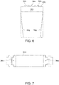
- a banknote storage bag 34q shown in FIG. 6 has a smaller periferal length of the inner space as a distance from the opening increases (that is, as going downward in FIG. 6 from the top edge of the banknote storage bag 34q). More specifically, the lateral width of the side surface of the banknote storage bag 34q is the maximum size at the position where the opening is provided, and the lateral width of the side surface becomes smaller as a distance from the opening increases. More specifically, as shown in FIG.
- the banknote storage bag 34q has a substantially rectangular shape, and an inner space is formed by adhering the inner surface of the portion near the side edge of the banknote storage bag 34q.
- a pair of right and left adhered parts on the inner surface of the banknote storage bag 34q is indicated by reference numeral 34g.
- the pair of right and left adhered parts 34g on the inner surface of the banknote storage bag 34q is inclined with respect to the side edge of the banknote storage bag 34q so as to approach each other as a distance from the opening increases.
- the lateral width of the side surface of the banknote storage bag 34q becomes smaller as a distance from the opening increases.
- FIG. 7 As shown in FIG. 7 , firstly, an oblong approximately rectangular shaped bag material 34m is prepared, and reinforcing members 34n are mounted to both ends of such a bag material 34m by heat sealing, for example. Thereafter, the bag material 34m is folded about a two-dot chain line extending in the vertical direction in FIG. 7 , and the left and right bag materials 34m face each other. Thereafter, the inner surface of a portion in the vicinity of the side edge of the folded bag material 34m is adhered at a position indicated by the reference numeral 34g in FIG. 6 . Finally, two openings 34b are formed in the protrusion 34a provided in each reinforcing member 34n. As a result, the banknote storage bag 34q as shown in FIG. 6 is formed.
- a banknote storage bag 34r shown in FIG. 8 has a smaller periferal length of the inner space as a distance from the opening increases (that is, as going downward in FIG. 8 from the upper end edge of the banknote storage bag 34r). More specifically, the lateral width of the side surface of the banknote storage bag 34r is the maximum size at the position where the opening is provided, and the lateral width of the side surface becomes smaller as a distance from the opening increases.
- the banknote storage bag 34r includes a reinforcing member 34h provided in the vicinity of opening, a first portion 34i which is provided on the side close to opening and in which the periferal length of the inner space decreases as a distance from the opening increases, and a second portion 34j which is provided farther from the opening than the first portion 34i and in which the periferal length of the inner space is the same length.
- a banknote storage bag 34s shown in FIG. 9 has a smaller periferal length of the inner space as a distance from the opening increases (that is, as going downward in FIG. 9 from the upper end edge of the banknote storage bag 34s). More specifically, the lateral width of the side surface of the banknote storage bag 34s is the maximum size at the position where the opening is provided, and the lateral width of the side surface becomes smaller as a distance from the opening increases. More specifically, as shown in FIG.
- the banknote storage bag 34s has a substantially rectangular shape, and an inner space is formed by adhering the inner surface of a portion near the side edge of the banknote storage bag 34s.
- a pair of left and right adhered parts on the inner surface of the banknote storage bag 34s is indicated by reference numerals 34k and 34l.
- the substantially rectangular reinforcing member 34h extending across the entire width direction of the opening is provided. The upper end of the pair of left and right adhered parts 34k substantially coincides with the lower edge of the reinforcing member 34h.
- the pair of right and left adhered parts 34k is inclined with respect to the side edge of the banknote storage bag 34s so as to approach each other as a distance from the opening increases.
- the first portion 34i is formed between the pair of right and left adhered parts 34k and the periferal length of the inner space of the first portion 34i decreases as a distance from the opening increases.
- the pair of right and left adhered parts 34l following the pair of right and left adhered parts 34k extends parallel to the side edge of the banknote storage bag 34s.
- the pair of left and right adhered parts 34l is positioned farther from the opening than the pair of left and right adhered parts 34k, and the lower edge of each adhered part 34l substantially coincides with the lower edge of the banknote storage bag 34s.
- the second portion 34j is formed between the pair of left and right adhered parts 34l.
- the second portion 34j is provided on the side farther from the opening than the first portion 34i, and the periferal length of the inner space of the second portion 34j is the same length.
- a method of forming such a banknote storage bag 34s is substantially the same as the above-described method of forming the banknote storage bag 34q.
- each banknote storage bag 34p, 34q, 34r, and 34s described above is the largest size at the position where the opening is provided. Therefore, in the vicinity of the bottom portion of each banknote storage bag 34p, 34q, 34r, and 34s, the wasted portion of the internal space is reduced, so that it is possible to prevent the banknotes stored in a stacked state from collapsing.
- FIG. 10 the configuration of a conventional banknote storage bag is shown in FIG. 10 .
- a banknote storage bag 35 having a substantially rectangular shape and having an opening at its upper end has been conventionally used.
- the periferal length of the inner space is the same length at any position along the height direction of the banknote storage bag 35.
- reinforcing members are provided on the front surface side and the back surface side, respectively. Each reinforcing member is provided with a pair of protrusions 35a formed with two openings 35b.
- the width of the banknote storage bag 35 also becomes large. If the size of the lateral width of the banknote storage bag 35 is too larger than the length of the banknote in the longitudinal direction, there is a fear that the banknotes collapse inside the banknote storage bag 35 when a plurality of banknotes are stored in the storage bag in a stacked state. On the other hand, in the case of using the banknote storage bags 34p, 34q, 34r, and 34s described above, the periferal length of the inner space becomes smaller as a distance from the opening increases, so it is possible to prevent the occurrence of such a problem.
- the banknote handling machine 10 of the present embodiment comprises a controlling unit 50 for controlling components of the banknote handling machine 10. More specifically, as shown in FIG. 11 , the controlling unit 50 is connected to the components such as the banknote feeding mechanism 20a disposed in the inlet unit 20, a stacking wheel driving unit 22b for driving the stacking wheel 22a disposed in the outlet 22, the transporting unit 24, the diverged transporting unit 25, the recognition unit 26, the storage/feeding unit 30, the banknote storage mechanism 32 including the pantograph 37, the heating member 38, the regulating guide driving unit 39a, the stage driving unit 41, the heating member 42, the temporary storage unit 44, the pantograph 47 and the banknote sending unit 48.
- a signal relating to a recognition result of each banknote by the recognition unit 26 is sent to the controlling unit 50, and the controlling unit 50 controls the operation of the components by sending command signals to the components of the banknote handling machine 10, respectively.
- an operation/display unit 52 is, for example, a touch panel or the like disposed on the upper surface of the housing 12, and information on processing state such as deposit processing of the banknotes in the banknote handling machine 10, information on the inventory amount of the banknotes stored in each banknote storage bag 34 and the like are displayed on the operation/display unit 52. Further, the operator can give various instructions to the controlling unit 50 by operating the operation/display unit 52.
- the memory unit 54 memorizes processing history such as deposit processing of the banknotes in the banknote handling machine 10 and information on the inventory amount of the banknotes stored in each banknote storage bag 34.
- the printing unit 56 prints processing history such as deposit processing of the banknotes in the banknote handling machine 10 and information on the inventory amount of the banknotes stored in each banknote storage bag 34 on a receipt or the like.
- the controlling unit 50 sends and receives signals to and from an external device disposed separately from the banknote handling machine 10 according to the present embodiment (for example, an upper terminal) via the communication interface unit 58. Specifically, the controlling unit 50 can send the information stored in the memory unit 54 to the external device disposed separately from the banknote handling machine 10 via the communication interface unit 58. For example, when security guards of a cash-in-transit company collect banknotes together with the banknote storage bag 34, information on the collected banknotes is transmitted to the computer of the cash-in-transit company by the communication interface unit 58.
- the operation on which deposit processing of the banknotes is performed in the banknote handling machine 10 will be described.
- the operator puts the banknotes into the inlet unit 20 the operator gives a command of starting deposit processing to the controlling unit 50 through the operation/display unit 52.
- the banknotes put into the inlet unit 20 are fed out one by one into the housing 12 by the banknote feeding mechanism 20a and are transported one by one by the transporting unit 24.
- Each banknote transported by the transporting unit 24 is recognized by the recognition unit 26 for the denomination, authenticity, front/back, fitness, new/old, transportation state, and the like.
- the banknote recognized as not being a normal banknote by the recognition unit 26, namely a reject banknote, is sent to the outlet 22 by the transporting unit 24 and stacked in the outlet 22. Accordingly, the operator can manually take out the reject banknote stacked in the outlet 22 from the front surface of the housing 12 and reinsert it into the inlet unit 20.
- the banknote recognized by the recognition unit 26 as being a normal banknote is sent from the transporting unit 24 to the diverged transporting unit 25, and then the banknote is sent from the diverged transporting unit 25 to the banknote storage bag 34 and stored therein.
- the banknote storage bag 34 to which the banknotes recognized by the recognition unit 26 are to be sent is in a full state or a near full state and the banknote storage bag 34 can not store the banknotes any more, the banknotes recognized by the recognition unit 26 are sent to the storage/feeding unit 30 and stored in the storage/feeding unit 30.
- banknote storage bag 34 in the full state or the near full state is taken out from the banknote storage mechanism 32 of the lower assembly 16 by the security guard of the cash-in-transit company or the clerk of the store and then an empty banknote storage bag 34 is mounted to the banknote storage mechanism 32, the banknotes are fed out one by one from the storage/feeding unit 30 to the transporting unit 24 and sent to the banknote storage bag 34 by the transporting unit 24.
- each banknote storage mechanism 32 an operation when storing the banknotes, sent from the diverged transporting unit 25 of the upper assembly 14 to the lower assembly 16, in the banknote storage bag 34 held by the pair of holding members 36 will be described.
- the banknotes sent from the diverged transporting unit 25 of the upper assembly 14 to the lower assembly 16 are sent by the banknote sending unit 48 onto the pair of the temporary storage units 44 and are stacked on the temporary storage units 44. Then, when a predetermined number of banknotes are stacked on the temporary storage units 44, as each temporary storage unit 44 rotates around the shaft 44a provided at the proximal end portion thereof downwardly (that is, in the direction of the arrow in FIG. 2 ), the banknotes stacked on the temporary storage units 44 fall from the temporary storage units 44 due to their own weight and are stored in the banknote storage bag 34. When the banknotes fall from the temporary storage units 44 and are stored in the banknote storage bag 34, each stage 40 is moved downward by the stage driving unit 41.
- the controlling unit 50 controls the pantograph 47 so as to push the banknotes held on the temporary storage units 44 into the banknote storage bag 34 by the pusher plate 46.
- the controlling unit 50 may control the pantograph 47 so as to bring the pusher plate 46 into the banknote storage bag 34 and press the bottom of the banknote storage bag 34 toward each stage 40 via the banknotes stored in the banknote storage bag 34.
- the banknotes stored in a stacked state inside the banknote storage bag 34 are compressed in the stacking direction. Therefore, it is possible to further prevent the banknotes stored in the banknote storage bag 34 from collapsing.
- the opening is provided at the upper end edge, and the periferal length of the inner space is the largest size at the position where the opening is provided.
- the periferal length of the inner space of the banknote storage bag 34, 34p, 34q, 34r and 34s is approximately the same as the size twice the lateral width of the side surface when no gore is provided.
- the circumference length of the internal space of the banknote storage bag 34, 34p, 34q, 34r and 34s is as large as total of the size twice the width of the side surface and twice the width of the gore.
- a plurality of banknotes are stored in a stacked state.
- the periferal length of the inner space of the banknote storage bag 34, 34p, 34q, 34r and 34s is the largest size at the position where the opening is provided, the wasted portion of the internal space becomes small in the vicinity of the bottom of the banknote storage bag 34, 34p, 34q, 34r and 34s. Therefore, it is possible to prevent the banknotes stored in a stacked state from collapsing.
- the periferal length of the inner space decreases as a distance from the opening increases.
- the lateral width of the side surface is the maximum size at the position where the opening is provided, and the lateral width of the side surface decreases as a distance from the opening increases.
- the reinforcing member 34c, 34n and 34h for reinforcing the side surface of the banknote storage bag 34, 34q, 34r and 34s is provided in the vicinity of the opening as described above.
- the periferal length of the inner space is the same length at the position where the reinforcing member 34c, 34n, 34h is provided.
- the banknote storage bag 34q and 34s of the present embodiment has a substantially rectangular shape, and an inner space is formed by adhering the inner surface of the portion near the side edge of the banknote storage bag 34q and 34s.
- each of the banknote storage bag 34r and 34s of the present embodiment includes the first portion 34i which is provided on the side close to the opening and in which the periferal length of the inner space decreases as a distance from the opening increases, and the second portion 34j which is provided on the side farther from the opening than the first portion 34i and in which the periferal length of the inner space is the same length.
- the banknote handling machine 10 (sheet handling apparatus) of the present embodiment, in which the banknote storage bag 34 described above is detachably mounted, includes the pair of right and left holding members 36 for holding a portion of the banknote storage bag 34 in the vicinity of the opening in the banknote storage bag 34, and the stage 40 (platform) which is movable in a substantially vertical direction and at least part of the banknote storage bag 34 held by the holding member 36 is placed thereon.
- the distance between the holding members 36 when holding the banknote storage bag 34 is larger than the width of the stage 40.
- the banknote storage bag 34 even if the periferal length of the inner space of the banknote storage bag 34 is the maximum size at the opening, the banknote storage bag 34, at least a part of which is placed on the stage 40, can be reliably held by each holding member 36.
- the pair of left and right regulating guides 39 (regulating member) for regulating the respective sides of the banknote storage bag 34 held by each holding member 36 is provided.
- the distance between the holding members 36 when holding the banknote storage bag 34 is larger than the distance between the regulating guides 39.
- each regulating guide 39 facing the respective sides of the banknote storage bag 34 is inclined with respect to the vertical direction to approach each other as a distance from the opening of the banknote storage bag 34 held by each holding member 36 increases.
- the side edge of the tapered part 34d of the banknote storage bag 34 (that is, the side edge which is inclined with respect to the banknote stacking direction) can be reliably regulated by each regulating guide 39.
- the banknote handling machine 10 (sheet handling apparatus) of the present embodiment includes a temporary storage unit 44 for temporarily holding banknotes to be stored in the banknote storage bag 34 held by the holding member 36, and the pusher plate 46 (pusher) which pushes the banknotes held by the temporary storage unit 44 into the banknote storage bag 34 held by each holding member 36, respectively.
- the pusher plate 46 pushes the banknotes held by the temporary storage unit 44 into the banknote storage bag 34 held by each holding member 36, respectively.
- the banknotes stored inside the banknote storage bag 34 in a stacked state are compressed in the stacking direction. Therefore, it is possible to further prevent the banknotes stored in the banknote storage bag 34 from collapsing.
- banknote storage bag according to the present embodiment and the banknote handling machine to which such a banknote storage bag can be detachably mounted are not limited to the above described aspects, and various modifications can be conducted.
- the banknote storage bag according to the present embodiment is not limited to the one shown in FIGS. 4 to 9 .
- a banknote storage bag according to the present embodiment if the opening is provided at the upper end edge and the periferal length of the inner space is the maximum size at the position where the opening is provided, a banknote storage bag having a configuration other than the shape as shown in FIGS. 4 to 9 may be used.
- the storage bag according to the present invention is not limited to a banknote storage bag for storing the banknotes.
- a storage bag according to the present invention a storage bag that stores sheets (for example, checks, vouchers, and the like) other than the banknotes may be used.
- the sheet handling apparatus according to the present invention is not limited to the banknote handling machine. An apparatus for handling sheets other than the banknotes can be used as the sheet handling apparatus according to the present invention and a storage bag according to the present invention may be detachably mounted to such a sheet handling apparatus.
Landscapes
- Physics & Mathematics (AREA)
- General Physics & Mathematics (AREA)
- Engineering & Computer Science (AREA)
- Mechanical Engineering (AREA)
- Business, Economics & Management (AREA)
- Accounting & Taxation (AREA)
- Finance (AREA)
- Pile Receivers (AREA)
Abstract
Description
- The present invention relates to a storage bag in which sheets such as banknotes are stored, and a sheet handling apparatus to which such a storage bag can be detachably mounted.
- As a banknote handling machine for performing various processes such as deposit processing and dispense processing of banknotes, there has been conventionally used one in which the banknotes taken in into a housing are stored in a storage bag such as a pouch bag. As such a banknote handling machine, for example, one disclosed in Japanese Patent Application Laid-Open No.
2014-174581 JP2014-174581A 2014-174581 - The conventional storage bag has a substantially rectangular shape, and a lateral width of a side surface of the storage bag is about the same size from the opening to the bottom. However, if such a storage bag is used, there is a problem that the banknotes stored in the storage bag in a stacked state tend to collapse. More specifically, in order to ensure that the banknotes are stored in the storage bag, it is necessary to make the opening provided at an upper end of the storage bag as large as possible, but if the size of the opening is increased, the lateral width of the storage bag also becomes large. When the lateral width of the storage bag is much larger than the length of the banknote in the longitudinal direction, there is a possibility that the banknotes collapse inside the storage bag when a plurality of banknotes is stored in the storage bag in a stacked state.
- The present invention has been made in view of these points, and an object of the present invention is to provide a storage bag capable of preventing banknotes stored in a stacked state from collapsing. Another object of the present invention is to provide a sheet handling apparatus which can store banknotes in the storage bag in such a manner that the banknotes in a stacked state are not collapsed as much as possible.
- A storage bag of the present invention mounted to a sheet handling apparatus and configured to store sheets handled by the sheet handling apparatus includes: an upper end at which an opening is provided; and a periferal length of an internal space of the storage bag at a position where the opening is provided is the maximum size.
- In the storage bag of the present invention, a plurality of sheets may be stored in the storage bag in a stacked state.
- In the storage bag of the present invention, the periferal length of the internal space may decrease as a distance from the opening increases.
- In the storage bag of the present invention, a lateral width of a side surface of the storage bag may be the maximum size at the position where the opening is provided, and the lateral width of the side surface of the storage bag may decrease as a distance from the opening increases.
- In the storage bag of the present invention, a reinforcing unit for reinforcing a side surface of the storage bag may be provided in the vicinity of the opening, and the periferal length of the internal space at a position where the reinforcing unit is provided may be the same length.
- In the storage bag of the present invention, the storage bag may have a substantially rectangular shape, and the internal space may be formed by adhering an internal surface of a portion near an edge of the storage bag.
- In the storage bag of the present invention, the storage bag may include a first portion which is provided on a side close to the opening and the periferal length of the internal space decreases as a distance from the opening increases, and a second portion which is provided on a side farther from the opening than the first portion and having a constant periferal length of the internal space.
- A sheet handling apparatus of the present invention to which a storage bag as described above is detachably mounted includes: a pair of left and right holding members configured to hold a portion of the storage bag in the vicinity of the opening; and a platform on which at least a part of the storage bag held by the holding members is placed, the platform being movable in a substantially vertical direction, and a distance between the holding members when holding the storage bag is larger than a width of the platform.
- The sheet handling apparatus of the present invention may further include a pair of left and right regulating members configured to regulate respective sides of the storage bag held by each holding member, and the distance between the holding members when holding the storage bag is larger than a distance between the regulating members.
- In this case, the surface of each regulating member that faces the respective sides of the storage bag may be inclined with respect to a vertical direction so as to approach each other as a distance from the opening of the storage bag held by the holding members increases.
- The sheet handling apparatus of the present invention may further include: a temporary storage unit configured to temporarily hold a sheet to be stored in the storage bag held by the holding members; and a pusher for pushing the sheets held by the temporary storage unit into the inside of the storage bag held by the holding members.
-
-
FIG. 1 is a schematic configuration diagram schematically showing an internal configuration of a banknote handling machine according to an embodiment of the present invention. -
FIG. 2 is a side view showing a detail of a configuration of a banknote storage mechanism in the banknote handling machine shown inFIG. 1 . -
FIG. 3 is a perspective view showing a configuration of a pair of holding members and the like in the banknote storage mechanism shown inFIG. 2 . -
FIG. 4 is a side view showing an example of a configuration of a banknote storage bag to be held by each holding member of the banknote storage mechanism shown inFIG. 2 and the like. -
FIG. 5 is a side view showing another example of a configuration of a banknote storage bag to be held by each holding member of the banknote storage mechanism shown inFIG. 2 and the like. -
FIG. 6 is a side view showing still another example of a configuration of a banknote storage bag to be held by each holding member of the banknote storage mechanism shown inFIG. 2 and the like. -
FIG. 7 is an explanatory diagram showing a method of forming the banknote storage bag shown inFIG. 6 . -
FIG. 8 is a side view showing still another example of a configuration of a banknote storage bag to be held by each holding member of the banknote storage mechanism shown inFIG. 2 and the like. -
FIG. 9 is a side view showing still another example of a configuration of a banknote storage bag to be held by each holding member of the banknote storage mechanism shown inFIG. 2 and the like. -
FIG. 10 is a side view showing a configuration of a conventional banknote storage bag. -
FIG. 11 is a functional block diagram showing a configuration of a control system of the banknote handling machine shown inFIG. 1 and the like. - Hereinafter, embodiments of the present invention will be described with reference to the drawings.
FIGS. 1 to 11 are diagrams showing a banknote handling machine according to the present embodiment and a banknote storage bag mounted to a mounting unit of such a banknote handling machine. Among these diagrams,FIG. 1 is a schematic configuration diagram schematically showing an internal configuration of the banknote handling machine according to the present embodiment,FIG. 2 is a side view showing a detail of a configuration of a banknote storage mechanism in the banknote handling machine shown inFIG. 1 , andFIG. 3 is a perspective view showing a configuration of a pair of holding members and the like in the banknote storage mechanism shown inFIG. 2 .FIGS. 4 to 9 are side views showing various examples of configurations of banknote storage bag to be held by each holding member of the banknote storage mechanism shown inFIG. 2 and the like. Note thatFIG. 10 is a side view showing a configuration of a conventional banknote storage bag. Further,FIG. 11 is a functional block diagram showing a configuration of a control system of the banknote handling machine shown inFIG. 1 and the like. - A
banknote handling machine 10 according to the present embodiment is generally installed in a front office area or back office area of a store such as a supermarket, or placed in a lobby of a bank or an inside of the bank, and thebanknote handling machine 10 can perform various processes such as deposit processing of banknotes. As shown inFIG. 1 , thebanknote handling machine 10 according to the present embodiment has a substantially rectangularparallelepiped housing 12. A left side surface of thehousing 12 inFIG. 1 is a front surface of the housing 12 (that is, the surface facing an operator). Anupper assembly 14 and alower assembly 16 are arranged inside thehousing 12 such that theupper assembly 14 and thelower assembly 16 can be respectively drawn forward from the front surface of the housing 12 (specifically, to the left inFIG. 1 ). In theupper assembly 14, aninlet unit 20 such as a hopper for taking in the banknotes from outside into inside thehousing 12 is disposed at an upper part of the front surface of the housing 12 (the upper part of the left side surface inFIG. 1 ). Further, in theupper assembly 14, an outlet 22 for feeding out the banknotes from inside thehousing 12 to outside is disposed below theinlet unit 20 in the front surface of the housing 12 (the surface on the left side inFIG. 1 ). - The
inlet unit 20 is provided with abanknote feeding mechanism 20a for feeding the banknotes, placed on theinlet unit 20 in a stacked state by the operator, one by one into thehousing 12. Atransporting unit 24 for transporting the banknotes one by one in thehousing 12 is disposed in theupper assembly 14 in thehousing 12 of thebanknote handling machine 10. The banknotes fed out from theinlet unit 20 by thebanknote feeding mechanism 20a are transported one by one by thetransporting unit 24. Thetransporting unit 24 is provided with arecognition unit 26. Each banknote fed out to thetransporting unit 24 by thebanknote feeding mechanism 20a is recognized by therecognition unit 26 for the denomination, authenticity, front/back, fitness, new/old, transportation state, and the like. - As shown in
FIG. 1 , the outlet 22 is connected to thetransporting unit 24, and the banknote sent from thetransporting unit 24 to the outlet 22 is stacked in the outlet 22. The outlet 22 is accessible from outside thehousing 12 so that the operator can take out the banknotes stacked in the outlet 22 from the front surface of thehousing 12. Astacking wheel 22a is disposed at a connection point between thetransporting unit 24 and the outlet 22, and thestacking wheel 22a is adapted to rotate in a counterclockwise direction inFIG. 1 . When the banknote is sent from thetransporting unit 24 to the outlet 22, thestacking wheel 22a rotates in the counterclockwise direction inFIG. 1 in a state in which the banknote is held between two blades of thestacking wheel 22a. Then, the banknote held between the two blades of thestacking wheel 22a is stacked in the outlet 22 in an aligned state. - In the
upper assembly 14, thetransporting unit 24 is provided with a tape-type storage/feeding unit 30. The banknote sent from thetransporting unit 24 to the storage/feeding unit 30 is stored in the storage/feeding unit 30 and the banknotes stored in the storage/feeding unit 30 can be fed out one by one to thetransporting unit 24. More specifically, the storage/feeding unit 30 is provided with adrum 30a rotatable in both forward and reverse directions, and one end of a pair of band-shaped tapes 31 is connected to an outer peripheral surface of thedrum 30a. When the banknote is sent from thetransporting unit 24 to the storage/feeding unit 30, the banknote is wound on thedrum 30a by each band-shaped tape 31 such that the banknote and eachtape 31 are integrally wound on thedrum 30a. On the other hand, when eachtape 31 is rewound from thedrum 30a by rotating thedrum 30a in the reverse direction, the banknote wound on thedrum 30a is discharged from eachtape 31 and is fed out to thetransporting unit 24. - As shown in
FIG. 1 , in the present embodiment, a plurality of (for example, two)banknote storage mechanisms 32 is provided in thelower assembly 16 to store banknotes inside abanknote storage bag 34 having an opening on one side. Eachbanknote storage mechanism 32 is provided with a pair of holdingmembers 36 which space apart from each other and face each other. Two portions of thebanknote storage bag 34, facing each other in the vicinity of the opening of thebanknote storage bag 34, are held by the pair of holdingmembers 36, respectively. One holding member 36 (For example, the holdingmember 36 on the right side inFIGS. 1 and2 ) is fixed in a fixed position and does not move from the fixed position. In contrast, the other holding member 36 (For example, the holdingmember 36 on the left side inFIGS. 1 and2 ) can move towards the one holdingmember 36 fixed in the fixed positon. As shown inFIG. 2 , each holdingmember 36 is provided with aheating member 38. After a predetermined amount of the banknotes are stored in thebanknote storage bag 34 held by the holdingmembers 36 in thebanknote storage mechanism 32, before thebanknote storage bag 34 is taken out from thebanknote storage mechanism 32, the one holdingmember 36 moves toward the other holdingmember 36. Then, the two holdingmembers 36 are in contact with each other via thebanknote storage bag 34, and theheating members 38 heat the portion near the opening of thebanknote storage bag 34. As a result, the opening of thebanknote storage bag 34 is sealed by heat. In thebanknote storage mechanism 32, instead of moving the one holdingmembers 36 of the pair of holdingmembers 36 towards the other holdingmember 36, both holdingmembers 36 may be moved to a center position towards each other so that the two holdingmembers 36 touch each other in the center position. - A plurality (two in the example shown in
FIG. 1 ) of diverged transportingunits 25, corresponding to thebanknote storage mechanisms 32 respectively, diverge from the transportingunit 24 in theupper assembly 14. The banknotes transported from the transportingunit 24 to the diverged transportingunits 25 are sent from the diverged transportingunits 25 to thebanknote storage bags 34 mounted to thebanknote storage mechanisms 32 respectively, and stored in thebanknote storage bags 34. - Next, the configuration of the
banknote storage mechanism 32 in the present embodiment will be described in detail with reference toFIGS. 2 and3 .FIG. 2 is a side view showing details of the configuration of thebanknote storage mechanism 32, andFIG. 3 is a perspective view showing a configuration of a pair of holdingmembers 36 and the like in thebanknote storage mechanism 32 shown inFIG. 2 . - As shown in
FIG. 2 , thebanknote storage mechanism 32 is provided with abanknote sending unit 48,temporary storage unit 44, and stages 40. The banknotes are transported from the diverged transportingunit 25 of theupper assembly 14 to thebanknote sending unit 48 located in thelower assembly 16, and then, sent to thebanknote storage bag 34 held by the pair of holdingmembers 36. The banknotes sent from thebanknote sending unit 48 are temporarily stored on thetemporary storage unit 44. The bottom of thebanknote storage bag 34 held by the pair of holdingmembers 36 is placed on thestage 40. - As shown in
FIG. 2 , thebanknote sending unit 48 is a combination of roller and belt. The banknotes are transported from the diverged transportingunit 25 of theupper assembly 14 to thebanknote sending unit 48 of thelower assembly 16. Then, the banknotes transported to thebanknote sending unit 48 are sent onto thetemporary storage unit 44 one by one, and then stacked on thetemporary storage unit 44. Thetemporary storage unit 44 consists of a pair of left and right. Eachtemporary storage unit 44 can rotate downward (that is, in the direction of the arrow inFIG. 2 ) around ashaft 44a provided at the base end portion of eachtemporary storage unit 44. Thestage 40 consists of a pair of left and right. Eachstage 40 is movable in the vertical direction and the lateral direction inFIG. 2 . A gap is formed between the pair ofstages 40, and a part of thebanknote storage bag 34 held by the holdingmembers 36 extends downward from eachstage 40 through the gap. Note that eachstage 40 is driven by a stage driving unit 41 (seeFIG. 11 ) such as an electric actuator. - As shown in
FIG. 2 , eachstage 40 is provided with aheating member 42, respectively. Before thebanknote storage bag 34 is taken out from thebanknote storage mechanism 32, one stage 40 (for example, thestage 40 on the left side inFIG. 2 ) is moved toward the other stage 40 (for example, thestage 40 on the right side inFIG. 2 ) and thestages 40 are in contact with each other via thebanknote storage bag 34. Then, theheating members 42 heat a bottom portion of thebanknote storage bag 34 storing the banknotes therein, and the bottom portion of thebanknote storage bag 34 is sealed by heat. In thebanknote storage mechanism 32, instead of moving the onestage 40 of the pair ofstages 40 towards theother stage 40, bothstages 40 may move towards each other to the center position and thestages 40 may be in contact with each other at the center position. - As shown in
FIG. 3 , apantograph 37 is mounted to theleft holding member 36 of the pair of left and right holdingmembers 36. When theleft holding member 36 is moved by thepantograph 37 toward theright holding member 36, the pair of holdingmembers 36 are in contact with each other. More specifically, aguide pin 36p is disposed at an end of theleft holding member 36. In addition, a linearlong hole 36q for guiding theguide pin 36p is formed in aframe 36k for supporting each holdingmember 36. Note that thelong hole 36q is formed so as to extend in a horizontal direction in theframe 36k. When thepantograph 37 expands, theguide pin 36p disposed at theleft holding member 36 is guided along thelong hole 36q, whereby theleft holding member 36 is moved toward theright holding member 36. - Further, as shown in
FIG. 3 , twopin 36a are respectively disposed on upper surfaces of the pair of left and right holdingmembers 36. As shown inFIG. 4 , a pair ofprotrusions 34a each having twoopenings 34b are disposed at a location near the opening of thebanknote storage bag 34 to be held by the holding members 36 (that is, an upper end of the banknote storage bag 34). When thebanknote storage bag 34 is held by the holdingmembers 36, eachpin 36a of each holdingmember 36 passes through eachopening 34b formed in eachprotrusion 34a of thebanknote storage bag 34. As a result, theseprotrusions 34a are held by the holdingmembers 36. - As shown in
FIG. 2 , apusher plate 46 is disposed above the pair of thetemporary storage units 44. Thepusher plate 46 is provided with a pantograph 47 (seeFIG. 11 , not shown inFIG. 2 ), and thepusher plate 46 can be moved in the vertical direction within a range indicated by the arrow inFIG. 2 by thepantograph 47 expanding and contracting in the vertical direction inFIG. 2 . When the banknotes temporarily held on thetemporary storage unit 44 are stored in thebanknote storage bag 34, by moving thepusher plate 46 downward, it is possible to push the banknotes remaining on thetemporary storage units 44 toward thebanknote storage bag 34. - Below each holding
member 36, a pair of regulating guides 39 is provided outside of eachstage 40. Each regulatingguide 39 is movable in directions toward and away from each other. That is, each regulatingguide 39 can move in the lateral direction inFIG. 2 . These regulating guides 39 regulate respective sides of thebanknote storage bag 34 when many banknotes are stored in thebanknote storage bag 34 held by each holdingmember 36. Each regulatingguide 39 is moved in the lateral direction inFIG. 2 by a regulatingguide driving unit 39a (seeFIG. 11 ) including a pantograph, an electric actuator, or the like. - Each regulating
guide 39 has a plate shape having a large lateral width corresponding to a lateral width of thebanknote storage bag 34. It is noted that each regulatingguide 39 is not limited to a plate shape having a large lateral width. Each regulating guides 39 may be constituted by arranging a plurality of plate-like members having a small lateral width so as to correspond to the lateral width of thebanknote storage bag 34. Alternatively, each regulatingguide 39 may be composed of a plurality of rod-like members arranged so as to correspond to the lateral width of thebanknote storage bag 34. As described above, each regulatingguide 39 can be moved in the lateral direction inFIG. 2 by the regulatingguide driving unit 39a. By moving each regulatingguide 39 by the regulatingguide driving unit 39a, the distance between the opposing left and right regulating guides 39 is adjusted according to the width of the banknote stored in thebanknote storage bag 34. - In this manner, when many banknotes are stored in the
banknote storage bag 34 held by each holdingmember 36, the respective sides of thebanknote storage bag 34 when eachstage 40 moves downward are regulated by each regulatingguide 39. Thus, even if the height of the banknotes stored in thebanknote storage bag 34 increases, it is possible to prevent the banknotes from collapsing in thebanknote storage bag 34. - In the example shown in
FIG. 2 , the surfaces of the regulating guides 39 opposed to the respective sides of thebanknote storage bag 34 are inclined with respect to the vertical direction so as to approach each other as a distance from the opening of thebanknote storage bag 34 held by each holdingmember 36 increases (That is, as a distance from the upper end of thebanknote storage bag 34 inFIG. 2 increases). In addition, the distance between the regulating guides 39 is smaller than the distance between the holdingmembers 36 when holding thebanknote storage bag 34. - In addition to the pair of left and right regulating guides 39, a pair of regulating guides each having a similar configuration as the regulating
guide 39 may be provided on the near side and the far side of thebanknote storage bag 34 on the page ofFIG. 2 . In this case, the entire circumference of thebanknote storage bag 34 can be regulated by the regulating guides 39 and the regulating guides provided on the near side and the far side of thebanknote storage bag 34. Therefore, it is possible to more reliably prevent the banknotes from collapsing in thebanknote storage bag 34. - The dimension of the
stage 40 is designed according to the smallest size banknote among various kinds of banknotes to be stored in thebanknote storage bag 34. Then, even if the banknote having the smallest size is stored in thebanknote storage bag 34, thestage 40 and the regulatingguide 39 do not interfere with each other. In the case where a plurality of plate like members having a small lateral width or a plurality of rod-shaped members are arranged side by side as the regulatingguide 39, cutouts through which such plate like members or rod-shaped members pass may be provided in thestage 40 so that thestage 40 passes over the regulatingguide 39. In this case, the dimension of thestage 40 can be made larger than the width of the banknote. In the present embodiment, the distance between the holdingmembers 36 when holding thebanknote storage bag 34 is larger than the width of thestage 40 in the lateral direction inFIG. 2 . - Next, details of the configuration of the
banknote storage bag 34 which is detachably held by each holdingmember 36 in thebanknote storage mechanism 32 of thebanknote handling machine 10 according to the present embodiment will be described with reference toFIG. 4 . In the present embodiment, thebanknote storage bag 34 is provided with an opening at its upper end edge, and the periferal length of the internal space is the largest at a position where the opening is provided. Note that the periferal length of the inner space of thebanknote storage bag 34 is approximately the same as the size twice the lateral width of the side surface when no gore is provided in thebanknote storage bag 34. On the other hand, when a pair of gores is provided in thebanknote storage bag 34, the circumference length of the internal space of thebanknote storage bag 34 is as large as total of the size twice the width of the side surface and twice the width of the gore. Thebanknote storage bag 34 is designed to store a plurality of sheets in a stacked state. Details of the configuration of such abanknote storage bag 34 will be described below. - In the present embodiment, as shown in
FIG. 4 , the periferal length of the internal space of thebanknote storage bag 34 becomes small as a distance from the opening increases (that is, as going downward inFIG. 4 from the upper end edge of the banknote storage bag 34). More specifically, the lateral width of the side surface of thebanknote storage bag 34 is the maximum size at the position where the opening is provided, and the lateral width of the side surface of thebanknote storage bag 34 becomes smaller, as a distance from the opening increases. More specifically, thebanknote storage bag 34 includes a reinforcingmember 34c provided in the vicinity of the opening, and atapered part 34d which is provided on the side farther from the opening than the reinforcingmember 34c and whose periferal length decreases as a distance from the opening increases. The reinforcingmember 34c is provided on the front surface side and the back surface side of thebanknote storage bag 34. The periferal length of the inner space of thebanknote storage bag 34 is the same length at the position where each reinforcingmember 34c is provided. Each reinforcingmember 34c is provided with theprotrusion 34a formed with twoopenings 34b. When thebanknote storage bag 34 is held by each holdingmember 36, by passing eachpin 36a of each holdingmember 36 through eachopening 34b formed in eachprotrusion 34a of thebanknote storage bag 34, theseprotrusions 34a are held by each holdingmember 36. When thebanknote storage bag 34 having such a configuration is used, since the periferal length of the inner space of thebanknote storage bag 34 is the largest size at the position where the opening is provided, the wasted portion of the internal space becomes small in the vicinity of the bottom of thebanknote storage bag 34. Therefore, it is possible to prevent the banknotes stored in thebanknote storage bag 34 in a stacked state from collapsing. In particular, since thetapered part 34d in which the periferal length of the inner space decreases as a distance from the opening increases, it is possible to further securely prevent the banknotes stored in a stacked state inside thetapered part 34d from collapsing. - Note that the banknote storage bag detachably held by each holding
member 36 in thebanknote storage mechanism 32 of thebanknote handling machine 10 according to the present embodiment is not limited to the configuration shown inFIG. 4 . In the present embodiment, a banknote storage bag having a configuration other than thebanknote storage bag 34 shown inFIG. 4 may be used, if the opening is provided at the upper end edge and the periferal length of the inner space is the largest size at the position where the opening is provided. For example, a banknote storage bag 34p shown inFIG. 5 may be used. Specifically, in each of a reinforcingmember 34e and atapered part 34f of the banknote storage bag 34p, the periferal length of the inner space becomes gradually smaller as a distance from the opening increases. - Further, as a still another example of the banknote storage bag detachably held by each holding
member 36 in thebanknote storage mechanism 32 of thebanknote handling machine 10 of the present embodiment, one having a configuration as shown inFIG. 6 may be used. Similar to thebanknote storage bag 34 shown inFIG. 4 , abanknote storage bag 34q shown inFIG. 6 has a smaller periferal length of the inner space as a distance from the opening increases (that is, as going downward inFIG. 6 from the top edge of thebanknote storage bag 34q). More specifically, the lateral width of the side surface of thebanknote storage bag 34q is the maximum size at the position where the opening is provided, and the lateral width of the side surface becomes smaller as a distance from the opening increases. More specifically, as shown inFIG. 6 , thebanknote storage bag 34q has a substantially rectangular shape, and an inner space is formed by adhering the inner surface of the portion near the side edge of thebanknote storage bag 34q. A pair of right and left adhered parts on the inner surface of thebanknote storage bag 34q is indicated byreference numeral 34g. As shown inFIG. 6 , the pair of right and left adheredparts 34g on the inner surface of thebanknote storage bag 34q is inclined with respect to the side edge of thebanknote storage bag 34q so as to approach each other as a distance from the opening increases. As a result, the lateral width of the side surface of thebanknote storage bag 34q becomes smaller as a distance from the opening increases. A method of forming such abanknote storage bag 34q will be described with reference toFIG. 7 . As shown inFIG. 7 , firstly, an oblong approximately rectangular shapedbag material 34m is prepared, and reinforcingmembers 34n are mounted to both ends of such abag material 34m by heat sealing, for example. Thereafter, thebag material 34m is folded about a two-dot chain line extending in the vertical direction inFIG. 7 , and the left andright bag materials 34m face each other. Thereafter, the inner surface of a portion in the vicinity of the side edge of the foldedbag material 34m is adhered at a position indicated by thereference numeral 34g inFIG. 6 . Finally, twoopenings 34b are formed in theprotrusion 34a provided in each reinforcingmember 34n. As a result, thebanknote storage bag 34q as shown inFIG. 6 is formed. - As a still another example of the banknote storage bag detachably held by each holding
member 36 in thebanknote storage mechanism 32 of thebanknote handling machine 10 of the present embodiment, one having a configuration shown inFIG. 8 may be used. Similarly to thebanknote storage bag 34 shown inFIG. 4 , abanknote storage bag 34r shown inFIG. 8 has a smaller periferal length of the inner space as a distance from the opening increases (that is, as going downward inFIG. 8 from the upper end edge of thebanknote storage bag 34r). More specifically, the lateral width of the side surface of thebanknote storage bag 34r is the maximum size at the position where the opening is provided, and the lateral width of the side surface becomes smaller as a distance from the opening increases. More specifically, thebanknote storage bag 34r includes a reinforcingmember 34h provided in the vicinity of opening, afirst portion 34i which is provided on the side close to opening and in which the periferal length of the inner space decreases as a distance from the opening increases, and asecond portion 34j which is provided farther from the opening than thefirst portion 34i and in which the periferal length of the inner space is the same length. - As a still another example of the banknote storage bag detachably held by each holding
member 36 in thebanknote storage mechanism 32 of thebanknote handling machine 10 of the present embodiment, one having a configuration shown inFIG. 9 may be used. Similarly to thebanknote storage bag 34 shown inFIG. 4 , abanknote storage bag 34s shown inFIG. 9 has a smaller periferal length of the inner space as a distance from the opening increases (that is, as going downward inFIG. 9 from the upper end edge of thebanknote storage bag 34s). More specifically, the lateral width of the side surface of thebanknote storage bag 34s is the maximum size at the position where the opening is provided, and the lateral width of the side surface becomes smaller as a distance from the opening increases. More specifically, as shown inFIG. 9 , thebanknote storage bag 34s has a substantially rectangular shape, and an inner space is formed by adhering the inner surface of a portion near the side edge of thebanknote storage bag 34s. A pair of left and right adhered parts on the inner surface of thebanknote storage bag 34s is indicated byreference numerals 34k and 34l. As shown inFIG. 9 , in the vicinity of the opening of thebanknote storage bag 34s, the substantially rectangular reinforcingmember 34h extending across the entire width direction of the opening is provided. The upper end of the pair of left and right adheredparts 34k substantially coincides with the lower edge of the reinforcingmember 34h. The pair of right and left adheredparts 34k is inclined with respect to the side edge of thebanknote storage bag 34s so as to approach each other as a distance from the opening increases. Thus, in thebanknote storage bag 34s, thefirst portion 34i is formed between the pair of right and left adheredparts 34k and the periferal length of the inner space of thefirst portion 34i decreases as a distance from the opening increases. The pair of right and left adhered parts 34l following the pair of right and left adheredparts 34k extends parallel to the side edge of thebanknote storage bag 34s. The pair of left and right adhered parts 34l is positioned farther from the opening than the pair of left and right adheredparts 34k, and the lower edge of each adhered part 34l substantially coincides with the lower edge of thebanknote storage bag 34s. Thus, in thebanknote storage bag 34s, thesecond portion 34j is formed between the pair of left and right adhered parts 34l. Thesecond portion 34j is provided on the side farther from the opening than thefirst portion 34i, and the periferal length of the inner space of thesecond portion 34j is the same length. A method of forming such abanknote storage bag 34s is substantially the same as the above-described method of forming thebanknote storage bag 34q. - Similarly to the
banknote storage bag 34, the periferal length of the inner space of eachbanknote storage bag banknote storage bag - As a comparative example, the configuration of a conventional banknote storage bag is shown in
FIG. 10 . As shown inFIG. 10 , abanknote storage bag 35 having a substantially rectangular shape and having an opening at its upper end has been conventionally used. In such abanknote storage bag 35, the periferal length of the inner space is the same length at any position along the height direction of thebanknote storage bag 35. In the vicinity of the opening of thebanknote storage bag 35, reinforcing members are provided on the front surface side and the back surface side, respectively. Each reinforcing member is provided with a pair ofprotrusions 35a formed with twoopenings 35b. When thebanknote storage bag 35 is held by each holdingmember 36, by passing eachpin 36a of each holdingmember 36 through eachopening 35b formed in eachprotrusion 35a of thebanknote storage bag 35, theseprotrusions 35a are held by each holdingmember 36. However, in the case of using the conventionalbanknote storage bag 35 as shown inFIG. 10 , since the lateral width of the side surface is substantially the same size from the opening to the bottom, there was a problem that the banknotes stored in thebanknote storage bag 35 in a stacked state tend to collapse. More specifically, in order to reliably store the banknotes in thebanknote storage bag 35, it is necessary to make the opening provided at the upper end thereof as large as possible. However, if the size of the opening becomes large, the width of thebanknote storage bag 35 also becomes large. If the size of the lateral width of thebanknote storage bag 35 is too larger than the length of the banknote in the longitudinal direction, there is a fear that the banknotes collapse inside thebanknote storage bag 35 when a plurality of banknotes are stored in the storage bag in a stacked state. On the other hand, in the case of using thebanknote storage bags - The
banknote handling machine 10 of the present embodiment comprises a controllingunit 50 for controlling components of thebanknote handling machine 10. More specifically, as shown inFIG. 11 , the controllingunit 50 is connected to the components such as thebanknote feeding mechanism 20a disposed in theinlet unit 20, a stackingwheel driving unit 22b for driving the stackingwheel 22a disposed in the outlet 22, the transportingunit 24, the diverged transportingunit 25, therecognition unit 26, the storage/feeding unit 30, thebanknote storage mechanism 32 including thepantograph 37, theheating member 38, the regulatingguide driving unit 39a, thestage driving unit 41, theheating member 42, thetemporary storage unit 44, thepantograph 47 and thebanknote sending unit 48. A signal relating to a recognition result of each banknote by therecognition unit 26 is sent to the controllingunit 50, and the controllingunit 50 controls the operation of the components by sending command signals to the components of thebanknote handling machine 10, respectively. - In addition, as shown in
FIG. 11 , an operation/display unit 52, amemory unit 54, aprinting unit 56, and acommunication interface unit 58 are respectively connected to the controllingunit 50. As shown inFIG. 1 , the operation/display unit 52 is, for example, a touch panel or the like disposed on the upper surface of thehousing 12, and information on processing state such as deposit processing of the banknotes in thebanknote handling machine 10, information on the inventory amount of the banknotes stored in eachbanknote storage bag 34 and the like are displayed on the operation/display unit 52. Further, the operator can give various instructions to the controllingunit 50 by operating the operation/display unit 52. Thememory unit 54 memorizes processing history such as deposit processing of the banknotes in thebanknote handling machine 10 and information on the inventory amount of the banknotes stored in eachbanknote storage bag 34. Theprinting unit 56 prints processing history such as deposit processing of the banknotes in thebanknote handling machine 10 and information on the inventory amount of the banknotes stored in eachbanknote storage bag 34 on a receipt or the like. The controllingunit 50 sends and receives signals to and from an external device disposed separately from thebanknote handling machine 10 according to the present embodiment (for example, an upper terminal) via thecommunication interface unit 58. Specifically, the controllingunit 50 can send the information stored in thememory unit 54 to the external device disposed separately from thebanknote handling machine 10 via thecommunication interface unit 58. For example, when security guards of a cash-in-transit company collect banknotes together with thebanknote storage bag 34, information on the collected banknotes is transmitted to the computer of the cash-in-transit company by thecommunication interface unit 58. - Next, an operation of the
banknote handling machine 10 having such a configuration will be described. Note that the operation of thebanknote handling machine 10 as shown below is performed by the controllingunit 50 controlling each component of thebanknote handling machine 10. - First, the operation on which deposit processing of the banknotes is performed in the
banknote handling machine 10 will be described. After the operator puts the banknotes into theinlet unit 20, the operator gives a command of starting deposit processing to the controllingunit 50 through the operation/display unit 52. Then, the banknotes put into theinlet unit 20 are fed out one by one into thehousing 12 by thebanknote feeding mechanism 20a and are transported one by one by the transportingunit 24. Each banknote transported by the transportingunit 24 is recognized by therecognition unit 26 for the denomination, authenticity, front/back, fitness, new/old, transportation state, and the like. The banknote recognized as not being a normal banknote by therecognition unit 26, namely a reject banknote, is sent to the outlet 22 by the transportingunit 24 and stacked in the outlet 22. Accordingly, the operator can manually take out the reject banknote stacked in the outlet 22 from the front surface of thehousing 12 and reinsert it into theinlet unit 20. On the other hand, the banknote recognized by therecognition unit 26 as being a normal banknote is sent from the transportingunit 24 to the diverged transportingunit 25, and then the banknote is sent from the diverged transportingunit 25 to thebanknote storage bag 34 and stored therein. - If the
banknote storage bag 34 to which the banknotes recognized by therecognition unit 26 are to be sent is in a full state or a near full state and thebanknote storage bag 34 can not store the banknotes any more, the banknotes recognized by therecognition unit 26 are sent to the storage/feeding unit 30 and stored in the storage/feeding unit 30. Then, after thebanknote storage bag 34 in the full state or the near full state is taken out from thebanknote storage mechanism 32 of thelower assembly 16 by the security guard of the cash-in-transit company or the clerk of the store and then an emptybanknote storage bag 34 is mounted to thebanknote storage mechanism 32, the banknotes are fed out one by one from the storage/feeding unit 30 to the transportingunit 24 and sent to thebanknote storage bag 34 by the transportingunit 24. - Next, in each
banknote storage mechanism 32, an operation when storing the banknotes, sent from the diverged transportingunit 25 of theupper assembly 14 to thelower assembly 16, in thebanknote storage bag 34 held by the pair of holdingmembers 36 will be described. - The banknotes sent from the diverged transporting
unit 25 of theupper assembly 14 to thelower assembly 16 are sent by thebanknote sending unit 48 onto the pair of thetemporary storage units 44 and are stacked on thetemporary storage units 44. Then, when a predetermined number of banknotes are stacked on thetemporary storage units 44, as eachtemporary storage unit 44 rotates around theshaft 44a provided at the proximal end portion thereof downwardly (that is, in the direction of the arrow inFIG. 2 ), the banknotes stacked on thetemporary storage units 44 fall from thetemporary storage units 44 due to their own weight and are stored in thebanknote storage bag 34. When the banknotes fall from thetemporary storage units 44 and are stored in thebanknote storage bag 34, eachstage 40 is moved downward by thestage driving unit 41. By this way, a storage space of the banknotes, sent from thetemporary storage unit 44 to thebanknote storage bag 34 next time, is formed inside thebanknote storage bag 34. Further, in the present embodiment, when the banknotes are sent to the inside of thebanknote storage bag 34 held by each holdingmember 36 and stored in thebanknote storage bag 34, the controllingunit 50 controls thepantograph 47 so as to push the banknotes held on thetemporary storage units 44 into thebanknote storage bag 34 by thepusher plate 46. As a result, even if the banknotes remain on thetemporary storage units 44, such remaining banknotes can be dropped from thetemporary storage units 44 and stored in thebanknote storage bag 34. - Further, after the banknotes are stored in the
banknote storage bag 34 held by each holdingmember 36 and eachstage 40 is moved downward, the controllingunit 50 may control thepantograph 47 so as to bring thepusher plate 46 into thebanknote storage bag 34 and press the bottom of thebanknote storage bag 34 toward eachstage 40 via the banknotes stored in thebanknote storage bag 34. In this case, by pushing the banknotes into thebanknote storage bag 34 by thepusher plate 46, the banknotes stored in a stacked state inside thebanknote storage bag 34 are compressed in the stacking direction. Therefore, it is possible to further prevent the banknotes stored in thebanknote storage bag 34 from collapsing. - According to the
banknote storage bags banknote storage bag banknote storage bag banknote storage bag banknote storage bag banknote storage bag banknote storage bag - In the
banknote storage bag - In the
banknote storage bag member banknote storage bag member - In the
banknote storage bag banknote storage bag banknote storage bag - Further, as described above, each of the
banknote storage bag first portion 34i which is provided on the side close to the opening and in which the periferal length of the inner space decreases as a distance from the opening increases, and thesecond portion 34j which is provided on the side farther from the opening than thefirst portion 34i and in which the periferal length of the inner space is the same length. - The banknote handling machine 10 (sheet handling apparatus) of the present embodiment, in which the
banknote storage bag 34 described above is detachably mounted, includes the pair of right and left holdingmembers 36 for holding a portion of thebanknote storage bag 34 in the vicinity of the opening in thebanknote storage bag 34, and the stage 40 (platform) which is movable in a substantially vertical direction and at least part of thebanknote storage bag 34 held by the holdingmember 36 is placed thereon. In addition, the distance between the holdingmembers 36 when holding thebanknote storage bag 34 is larger than the width of thestage 40. In this case, even if the periferal length of the inner space of thebanknote storage bag 34 is the maximum size at the opening, thebanknote storage bag 34, at least a part of which is placed on thestage 40, can be reliably held by each holdingmember 36. - Further, in the banknote handling machine 10 (sheet handling apparatus) of the present embodiment, the pair of left and right regulating guides 39 (regulating member) for regulating the respective sides of the
banknote storage bag 34 held by each holdingmember 36 is provided. In addition, the distance between the holdingmembers 36 when holding thebanknote storage bag 34 is larger than the distance between the regulating guides 39. - In this case, even if the periferal length of the inner space of the
banknote storage bag 34 is the largest size at the position where the opening is provided, it is possible to reliably hold thebanknote storage bag 34, whose sides are regulated by each regulatingguide 39, by each holdingmember 36. Further, the surface of each regulatingguide 39 facing the respective sides of thebanknote storage bag 34 is inclined with respect to the vertical direction to approach each other as a distance from the opening of thebanknote storage bag 34 held by each holdingmember 36 increases. In this case, the side edge of thetapered part 34d of the banknote storage bag 34 (that is, the side edge which is inclined with respect to the banknote stacking direction) can be reliably regulated by each regulatingguide 39. - In addition, the banknote handling machine 10 (sheet handling apparatus) of the present embodiment includes a
temporary storage unit 44 for temporarily holding banknotes to be stored in thebanknote storage bag 34 held by the holdingmember 36, and the pusher plate 46 (pusher) which pushes the banknotes held by thetemporary storage unit 44 into thebanknote storage bag 34 held by each holdingmember 36, respectively. In this case, by pushing the banknotes into thebanknote storage bag 34 by thepusher plate 46, the banknotes stored inside thebanknote storage bag 34 in a stacked state are compressed in the stacking direction. Therefore, it is possible to further prevent the banknotes stored in thebanknote storage bag 34 from collapsing. - It should be noted that the banknote storage bag according to the present embodiment and the banknote handling machine to which such a banknote storage bag can be detachably mounted are not limited to the above described aspects, and various modifications can be conducted.
- For example, the banknote storage bag according to the present embodiment is not limited to the one shown in
FIGS. 4 to 9 . As the banknote storage bag according to the present embodiment, if the opening is provided at the upper end edge and the periferal length of the inner space is the maximum size at the position where the opening is provided, a banknote storage bag having a configuration other than the shape as shown inFIGS. 4 to 9 may be used. - Further, the storage bag according to the present invention is not limited to a banknote storage bag for storing the banknotes. As a storage bag according to the present invention, a storage bag that stores sheets (for example, checks, vouchers, and the like) other than the banknotes may be used. Also, the sheet handling apparatus according to the present invention is not limited to the banknote handling machine. An apparatus for handling sheets other than the banknotes can be used as the sheet handling apparatus according to the present invention and a storage bag according to the present invention may be detachably mounted to such a sheet handling apparatus.
Claims (11)
- A storage bag mounted to a sheet handling apparatus and configured to store sheets handled by the sheet handling apparatus comprising:an upper end at which an opening is provided;wherein a periferal length of an internal space of the storage bag at a position where the opening is provided is the maximum size.
- The storage bag according to claim 1, wherein a plurality of sheets is stored in the storage bag in a stacked state.
- The storage bag according to claim 1 or 2, wherein the periferal length of the internal space decreases as a distance from the opening increases.
- The storage bag according to any one of claims 1 to 3, wherein a lateral width of a side surface of the storage bag is the maximum size at the position where the opening is provided, and the lateral width of the side surface of the storage bag decreases as a distance from the opening increases.
- The storage bag according to any one of claims 1 to 4, wherein a reinforcing unit for reinforcing a side surface of the storage bag is provided in the vicinity of the opening, and the periferal length of the internal space at a position where the reinforcing unit is provided is the same length.
- The storage bag according to any one of claims 1 to 5, wherein the storage bag has a substantially rectangular shape, and the internal space is formed by adhering an internal surface of a portion near an edge of the storage bag.
- The storage bag according to any one of claims 1 to 5, wherein the storage bag comprises a first portion which is provided on a side close to the opening and the periferal length of the internal space decreases as a distance from the opening increases, and a second portion which is provided on a side farther from the opening than the first portion and having a constant periferal length of the internal space.
- A sheet handling apparatus to which a storage bag according to any one of claims 1 to 7 is detachably mounted comprising:a pair of left and right holding members configured to hold a portion of the storage bag in the vicinity of the opening; anda platform on which at least a part of the storage bag held by the holding members is placed, the platform being movable in a substantially vertical direction,wherein a distance between the holding members when holding the storage bag is larger than a width of the platform.
- The sheet handling apparatus according to claim 8, further comprising a pair of left and right regulating members configured to regulate respective sides of the storage bag held by each holding member,
wherein the distance between the holding members when holding the storage bag is larger than a distance between the regulating members. - The sheet handling apparatus according to claim 9, wherein the surface of each regulating member that faces the respective sides of the storage bag is inclined with respect to a vertical direction so as to approach each other as a distance from the opening of the storage bag held by the holding members increases.
- The sheet handling apparatus according to any one of claims 8 to 10, further comprising:a temporary storage unit configured to temporarily hold a sheet to be stored in the storage bag held by the holding members; anda pusher for pushing the sheets held by the temporary storage unit into the inside of the storage bag held by the holding members.
Applications Claiming Priority (2)
| Application Number | Priority Date | Filing Date | Title |
|---|---|---|---|
| JP2016136921A JP2019148839A (en) | 2016-07-11 | 2016-07-11 | Storage bag and paper sheet processing device |
| PCT/JP2017/022887 WO2018012228A1 (en) | 2016-07-11 | 2017-06-21 | Storage bag and paper sheet processing apparatus |
Publications (3)
| Publication Number | Publication Date |
|---|---|
| EP3483848A1 true EP3483848A1 (en) | 2019-05-15 |
| EP3483848A4 EP3483848A4 (en) | 2020-03-18 |
| EP3483848B1 EP3483848B1 (en) | 2024-05-08 |
Family
ID=60952016
Family Applications (1)
| Application Number | Title | Priority Date | Filing Date |
|---|---|---|---|
| EP17827358.7A Active EP3483848B1 (en) | 2016-07-11 | 2017-06-21 | Storage bag |
Country Status (4)
| Country | Link |
|---|---|
| US (1) | US10829334B2 (en) |
| EP (1) | EP3483848B1 (en) |
| JP (1) | JP2019148839A (en) |
| WO (1) | WO2018012228A1 (en) |
Families Citing this family (1)
| Publication number | Priority date | Publication date | Assignee | Title |
|---|---|---|---|---|
| JP7467953B2 (en) * | 2020-02-04 | 2024-04-16 | コニカミノルタ株式会社 | Paper conveying device and image forming device |
Family Cites Families (11)
| Publication number | Priority date | Publication date | Assignee | Title |
|---|---|---|---|---|
| JPS4727989Y1 (en) | 1969-02-06 | 1972-08-24 | ||
| JPS6130606U (en) | 1984-07-30 | 1986-02-24 | 株式会社川島製作所 | Mandrel for bag filling and packaging machine |
| DE9212634U1 (en) * | 1992-07-07 | 1992-11-12 | Kunststoff-Verarbeitungs KWF Alfred Buchelt, 8562 Hersbruck | Toast bread bag |
| IL111114A0 (en) * | 1994-09-30 | 1994-11-28 | Geller Avner | Package having a rectangular base and its manufacture |
| JP3848517B2 (en) | 2000-03-30 | 2006-11-22 | グローリー工業株式会社 | Coin sorting counter |
| GB2394939A (en) * | 2002-10-24 | 2004-05-12 | Clive Stevens | Bag for use in safe |
| JP5290032B2 (en) | 2009-04-14 | 2013-09-18 | 東洋自動機株式会社 | Bag packing method |
| JP2011118651A (en) | 2009-12-03 | 2011-06-16 | Glory Ltd | Currency counter |
| CN104884358B (en) * | 2012-12-20 | 2018-04-03 | 雀巢产品技术援助有限公司 | Flexible pouch with more big opening |
| JP2014174581A (en) * | 2013-03-06 | 2014-09-22 | Glory Ltd | Storage bag and paper sheet storage device |
| DE102016000782A1 (en) * | 2016-01-27 | 2017-07-27 | Anton Debatin GmbH Werk für werbende Verpackung | Banknote bag and method for its filling |
-
2016
- 2016-07-11 JP JP2016136921A patent/JP2019148839A/en active Pending
-
2017
- 2017-06-21 EP EP17827358.7A patent/EP3483848B1/en active Active
- 2017-06-21 WO PCT/JP2017/022887 patent/WO2018012228A1/en not_active Ceased
- 2017-06-21 US US16/316,423 patent/US10829334B2/en active Active
Also Published As
| Publication number | Publication date |
|---|---|
| EP3483848A4 (en) | 2020-03-18 |
| US20190248616A1 (en) | 2019-08-15 |
| US10829334B2 (en) | 2020-11-10 |
| JP2019148839A (en) | 2019-09-05 |
| EP3483848B1 (en) | 2024-05-08 |
| WO2018012228A1 (en) | 2018-01-18 |
Similar Documents
| Publication | Publication Date | Title |
|---|---|---|
| EP3263497B1 (en) | Paper sheet storage mechanism and paper sheet storage method | |
| CN101456495B (en) | Banknote handling apparatus | |
| KR100492203B1 (en) | Automated Teller Machine | |
| RU2632156C1 (en) | Impeller mechanism, device for stacking and piece of paper and method for processing paper sheets | |
| EP3651128A1 (en) | Money handling apparatus | |
| EP3392845B1 (en) | Paper sheet handling apparatus | |
| US10287121B2 (en) | Sheet handling apparatus and sheet handling method | |
| US20200361737A1 (en) | Medium processing device and automatic transaction device | |
| KR101665609B1 (en) | Cassette to Store Recovery Paper for Automatic Teller Machine | |
| EP3473555A1 (en) | Sheet handling apparatus and sheet handling method | |
| JP2019061426A (en) | Paper sheet processor and paper sheet processing method | |
| EP3483848B1 (en) | Storage bag | |
| JP6612988B2 (en) | Transport direction switching device and paper sheet handling device | |
| KR100893707B1 (en) | Method for detecting height of bundle of papers, and paper handling apparatus | |
| EP3489180B1 (en) | Banknote handling machine | |
| JP5484935B2 (en) | Paper sheet processing apparatus and paper sheet processing method | |
| JP2010052884A (en) | Paper sheet handling device | |
| KR102323433B1 (en) | Medium receiving discharging apparatus and medium processing apparatus including the same | |
| JPH08221636A (en) | Banknote handling device and automatic cash transaction device | |
| JP4619739B2 (en) | Banknote handling machine | |
| JP2020009218A (en) | Paper sheet sealing mechanism and paper sheet processing apparatus | |
| JP7194774B2 (en) | Money handling machine and money handling method | |
| JP6901614B2 (en) | Money processing machine | |
| JP7545143B2 (en) | Coin processing machine and coin packaging and dispensing device | |
| WO2013061470A1 (en) | Paper sheet handling device |
Legal Events
| Date | Code | Title | Description |
|---|---|---|---|
| STAA | Information on the status of an ep patent application or granted ep patent |
Free format text: STATUS: THE INTERNATIONAL PUBLICATION HAS BEEN MADE |
|
| PUAI | Public reference made under article 153(3) epc to a published international application that has entered the european phase |
Free format text: ORIGINAL CODE: 0009012 |
|
| STAA | Information on the status of an ep patent application or granted ep patent |
Free format text: STATUS: REQUEST FOR EXAMINATION WAS MADE |
|
| 17P | Request for examination filed |
Effective date: 20190130 |
|
| AK | Designated contracting states |
Kind code of ref document: A1 Designated state(s): AL AT BE BG CH CY CZ DE DK EE ES FI FR GB GR HR HU IE IS IT LI LT LU LV MC MK MT NL NO PL PT RO RS SE SI SK SM TR |
|
| AX | Request for extension of the european patent |
Extension state: BA ME |
|
| DAV | Request for validation of the european patent (deleted) | ||
| DAX | Request for extension of the european patent (deleted) | ||
| A4 | Supplementary search report drawn up and despatched |
Effective date: 20200218 |
|
| RIC1 | Information provided on ipc code assigned before grant |
Ipc: E05G 7/00 20060101ALI20200212BHEP Ipc: G07D 11/12 20190101ALI20200212BHEP Ipc: G07F 19/00 20060101ALI20200212BHEP Ipc: G07D 13/00 20060101AFI20200212BHEP Ipc: B65H 31/26 20060101ALI20200212BHEP |
|
| STAA | Information on the status of an ep patent application or granted ep patent |
Free format text: STATUS: EXAMINATION IS IN PROGRESS |
|
| 17Q | First examination report despatched |
Effective date: 20210226 |
|
| P01 | Opt-out of the competence of the unified patent court (upc) registered |
Effective date: 20230531 |
|
| GRAP | Despatch of communication of intention to grant a patent |
Free format text: ORIGINAL CODE: EPIDOSNIGR1 |
|
| STAA | Information on the status of an ep patent application or granted ep patent |
Free format text: STATUS: GRANT OF PATENT IS INTENDED |
|
| INTG | Intention to grant announced |
Effective date: 20231208 |
|
| GRAS | Grant fee paid |
Free format text: ORIGINAL CODE: EPIDOSNIGR3 |
|
| GRAA | (expected) grant |
Free format text: ORIGINAL CODE: 0009210 |
|
| STAA | Information on the status of an ep patent application or granted ep patent |
Free format text: STATUS: THE PATENT HAS BEEN GRANTED |
|
| AK | Designated contracting states |
Kind code of ref document: B1 Designated state(s): AL AT BE BG CH CY CZ DE DK EE ES FI FR GB GR HR HU IE IS IT LI LT LU LV MC MK MT NL NO PL PT RO RS SE SI SK SM TR |
|
| REG | Reference to a national code |
Ref country code: GB Ref legal event code: FG4D |
|
| REG | Reference to a national code |
Ref country code: CH Ref legal event code: EP |
|
| REG | Reference to a national code |
Ref country code: DE Ref legal event code: R096 Ref document number: 602017081814 Country of ref document: DE |
|
| REG | Reference to a national code |
Ref country code: IE Ref legal event code: FG4D |
|
| REG | Reference to a national code |
Ref country code: LT Ref legal event code: MG9D |
|
| REG | Reference to a national code |
Ref country code: NL Ref legal event code: MP Effective date: 20240508 |
|
| PG25 | Lapsed in a contracting state [announced via postgrant information from national office to epo] |
Ref country code: IS Free format text: LAPSE BECAUSE OF FAILURE TO SUBMIT A TRANSLATION OF THE DESCRIPTION OR TO PAY THE FEE WITHIN THE PRESCRIBED TIME-LIMIT Effective date: 20240908 |
|
| PG25 | Lapsed in a contracting state [announced via postgrant information from national office to epo] |
Ref country code: BG Free format text: LAPSE BECAUSE OF FAILURE TO SUBMIT A TRANSLATION OF THE DESCRIPTION OR TO PAY THE FEE WITHIN THE PRESCRIBED TIME-LIMIT Effective date: 20240508 |
|
| PG25 | Lapsed in a contracting state [announced via postgrant information from national office to epo] |
Ref country code: HR Free format text: LAPSE BECAUSE OF FAILURE TO SUBMIT A TRANSLATION OF THE DESCRIPTION OR TO PAY THE FEE WITHIN THE PRESCRIBED TIME-LIMIT Effective date: 20240508 Ref country code: FI Free format text: LAPSE BECAUSE OF FAILURE TO SUBMIT A TRANSLATION OF THE DESCRIPTION OR TO PAY THE FEE WITHIN THE PRESCRIBED TIME-LIMIT Effective date: 20240508 |
|
| PG25 | Lapsed in a contracting state [announced via postgrant information from national office to epo] |
Ref country code: GR Free format text: LAPSE BECAUSE OF FAILURE TO SUBMIT A TRANSLATION OF THE DESCRIPTION OR TO PAY THE FEE WITHIN THE PRESCRIBED TIME-LIMIT Effective date: 20240809 |
|
| PG25 | Lapsed in a contracting state [announced via postgrant information from national office to epo] |
Ref country code: PT Free format text: LAPSE BECAUSE OF FAILURE TO SUBMIT A TRANSLATION OF THE DESCRIPTION OR TO PAY THE FEE WITHIN THE PRESCRIBED TIME-LIMIT Effective date: 20240909 |
|
| REG | Reference to a national code |
Ref country code: AT Ref legal event code: MK05 Ref document number: 1685667 Country of ref document: AT Kind code of ref document: T Effective date: 20240508 |
|
| PG25 | Lapsed in a contracting state [announced via postgrant information from national office to epo] |
Ref country code: NL Free format text: LAPSE BECAUSE OF FAILURE TO SUBMIT A TRANSLATION OF THE DESCRIPTION OR TO PAY THE FEE WITHIN THE PRESCRIBED TIME-LIMIT Effective date: 20240508 |
|
| PG25 | Lapsed in a contracting state [announced via postgrant information from national office to epo] |
Ref country code: ES Free format text: LAPSE BECAUSE OF FAILURE TO SUBMIT A TRANSLATION OF THE DESCRIPTION OR TO PAY THE FEE WITHIN THE PRESCRIBED TIME-LIMIT Effective date: 20240508 |
|
| PG25 | Lapsed in a contracting state [announced via postgrant information from national office to epo] |
Ref country code: AT Free format text: LAPSE BECAUSE OF FAILURE TO SUBMIT A TRANSLATION OF THE DESCRIPTION OR TO PAY THE FEE WITHIN THE PRESCRIBED TIME-LIMIT Effective date: 20240508 |
|
| PG25 | Lapsed in a contracting state [announced via postgrant information from national office to epo] |
Ref country code: PL Free format text: LAPSE BECAUSE OF FAILURE TO SUBMIT A TRANSLATION OF THE DESCRIPTION OR TO PAY THE FEE WITHIN THE PRESCRIBED TIME-LIMIT Effective date: 20240508 |
|
| PG25 | Lapsed in a contracting state [announced via postgrant information from national office to epo] |
Ref country code: LV Free format text: LAPSE BECAUSE OF FAILURE TO SUBMIT A TRANSLATION OF THE DESCRIPTION OR TO PAY THE FEE WITHIN THE PRESCRIBED TIME-LIMIT Effective date: 20240508 |
|
| PG25 | Lapsed in a contracting state [announced via postgrant information from national office to epo] |
Ref country code: PT Free format text: LAPSE BECAUSE OF FAILURE TO SUBMIT A TRANSLATION OF THE DESCRIPTION OR TO PAY THE FEE WITHIN THE PRESCRIBED TIME-LIMIT Effective date: 20240909 Ref country code: PL Free format text: LAPSE BECAUSE OF FAILURE TO SUBMIT A TRANSLATION OF THE DESCRIPTION OR TO PAY THE FEE WITHIN THE PRESCRIBED TIME-LIMIT Effective date: 20240508 Ref country code: NO Free format text: LAPSE BECAUSE OF FAILURE TO SUBMIT A TRANSLATION OF THE DESCRIPTION OR TO PAY THE FEE WITHIN THE PRESCRIBED TIME-LIMIT Effective date: 20240808 Ref country code: NL Free format text: LAPSE BECAUSE OF FAILURE TO SUBMIT A TRANSLATION OF THE DESCRIPTION OR TO PAY THE FEE WITHIN THE PRESCRIBED TIME-LIMIT Effective date: 20240508 Ref country code: LV Free format text: LAPSE BECAUSE OF FAILURE TO SUBMIT A TRANSLATION OF THE DESCRIPTION OR TO PAY THE FEE WITHIN THE PRESCRIBED TIME-LIMIT Effective date: 20240508 Ref country code: IS Free format text: LAPSE BECAUSE OF FAILURE TO SUBMIT A TRANSLATION OF THE DESCRIPTION OR TO PAY THE FEE WITHIN THE PRESCRIBED TIME-LIMIT Effective date: 20240908 Ref country code: HR Free format text: LAPSE BECAUSE OF FAILURE TO SUBMIT A TRANSLATION OF THE DESCRIPTION OR TO PAY THE FEE WITHIN THE PRESCRIBED TIME-LIMIT Effective date: 20240508 Ref country code: GR Free format text: LAPSE BECAUSE OF FAILURE TO SUBMIT A TRANSLATION OF THE DESCRIPTION OR TO PAY THE FEE WITHIN THE PRESCRIBED TIME-LIMIT Effective date: 20240809 Ref country code: FI Free format text: LAPSE BECAUSE OF FAILURE TO SUBMIT A TRANSLATION OF THE DESCRIPTION OR TO PAY THE FEE WITHIN THE PRESCRIBED TIME-LIMIT Effective date: 20240508 Ref country code: ES Free format text: LAPSE BECAUSE OF FAILURE TO SUBMIT A TRANSLATION OF THE DESCRIPTION OR TO PAY THE FEE WITHIN THE PRESCRIBED TIME-LIMIT Effective date: 20240508 Ref country code: BG Free format text: LAPSE BECAUSE OF FAILURE TO SUBMIT A TRANSLATION OF THE DESCRIPTION OR TO PAY THE FEE WITHIN THE PRESCRIBED TIME-LIMIT Effective date: 20240508 Ref country code: AT Free format text: LAPSE BECAUSE OF FAILURE TO SUBMIT A TRANSLATION OF THE DESCRIPTION OR TO PAY THE FEE WITHIN THE PRESCRIBED TIME-LIMIT Effective date: 20240508 Ref country code: RS Free format text: LAPSE BECAUSE OF FAILURE TO SUBMIT A TRANSLATION OF THE DESCRIPTION OR TO PAY THE FEE WITHIN THE PRESCRIBED TIME-LIMIT Effective date: 20240808 |
|
| PG25 | Lapsed in a contracting state [announced via postgrant information from national office to epo] |
Ref country code: DK Free format text: LAPSE BECAUSE OF FAILURE TO SUBMIT A TRANSLATION OF THE DESCRIPTION OR TO PAY THE FEE WITHIN THE PRESCRIBED TIME-LIMIT Effective date: 20240508 |
|
| PG25 | Lapsed in a contracting state [announced via postgrant information from national office to epo] |
Ref country code: EE Free format text: LAPSE BECAUSE OF FAILURE TO SUBMIT A TRANSLATION OF THE DESCRIPTION OR TO PAY THE FEE WITHIN THE PRESCRIBED TIME-LIMIT Effective date: 20240508 |
|
| PG25 | Lapsed in a contracting state [announced via postgrant information from national office to epo] |
Ref country code: CZ Free format text: LAPSE BECAUSE OF FAILURE TO SUBMIT A TRANSLATION OF THE DESCRIPTION OR TO PAY THE FEE WITHIN THE PRESCRIBED TIME-LIMIT Effective date: 20240508 |
|
| PG25 | Lapsed in a contracting state [announced via postgrant information from national office to epo] |
Ref country code: RO Free format text: LAPSE BECAUSE OF FAILURE TO SUBMIT A TRANSLATION OF THE DESCRIPTION OR TO PAY THE FEE WITHIN THE PRESCRIBED TIME-LIMIT Effective date: 20240508 Ref country code: SK Free format text: LAPSE BECAUSE OF FAILURE TO SUBMIT A TRANSLATION OF THE DESCRIPTION OR TO PAY THE FEE WITHIN THE PRESCRIBED TIME-LIMIT Effective date: 20240508 |
|
| PG25 | Lapsed in a contracting state [announced via postgrant information from national office to epo] |
Ref country code: SM Free format text: LAPSE BECAUSE OF FAILURE TO SUBMIT A TRANSLATION OF THE DESCRIPTION OR TO PAY THE FEE WITHIN THE PRESCRIBED TIME-LIMIT Effective date: 20240508 |
|
| PG25 | Lapsed in a contracting state [announced via postgrant information from national office to epo] |
Ref country code: SM Free format text: LAPSE BECAUSE OF FAILURE TO SUBMIT A TRANSLATION OF THE DESCRIPTION OR TO PAY THE FEE WITHIN THE PRESCRIBED TIME-LIMIT Effective date: 20240508 Ref country code: SK Free format text: LAPSE BECAUSE OF FAILURE TO SUBMIT A TRANSLATION OF THE DESCRIPTION OR TO PAY THE FEE WITHIN THE PRESCRIBED TIME-LIMIT Effective date: 20240508 Ref country code: RO Free format text: LAPSE BECAUSE OF FAILURE TO SUBMIT A TRANSLATION OF THE DESCRIPTION OR TO PAY THE FEE WITHIN THE PRESCRIBED TIME-LIMIT Effective date: 20240508 Ref country code: EE Free format text: LAPSE BECAUSE OF FAILURE TO SUBMIT A TRANSLATION OF THE DESCRIPTION OR TO PAY THE FEE WITHIN THE PRESCRIBED TIME-LIMIT Effective date: 20240508 Ref country code: DK Free format text: LAPSE BECAUSE OF FAILURE TO SUBMIT A TRANSLATION OF THE DESCRIPTION OR TO PAY THE FEE WITHIN THE PRESCRIBED TIME-LIMIT Effective date: 20240508 Ref country code: CZ Free format text: LAPSE BECAUSE OF FAILURE TO SUBMIT A TRANSLATION OF THE DESCRIPTION OR TO PAY THE FEE WITHIN THE PRESCRIBED TIME-LIMIT Effective date: 20240508 |
|
| REG | Reference to a national code |
Ref country code: CH Ref legal event code: PL |
|
| PG25 | Lapsed in a contracting state [announced via postgrant information from national office to epo] |
Ref country code: MC Free format text: LAPSE BECAUSE OF FAILURE TO SUBMIT A TRANSLATION OF THE DESCRIPTION OR TO PAY THE FEE WITHIN THE PRESCRIBED TIME-LIMIT Effective date: 20240508 |
|
| REG | Reference to a national code |
Ref country code: DE Ref legal event code: R097 Ref document number: 602017081814 Country of ref document: DE |
|
| PG25 | Lapsed in a contracting state [announced via postgrant information from national office to epo] |
Ref country code: LU Free format text: LAPSE BECAUSE OF NON-PAYMENT OF DUE FEES Effective date: 20240621 |
|
| PLBE | No opposition filed within time limit |
Free format text: ORIGINAL CODE: 0009261 |
|
| STAA | Information on the status of an ep patent application or granted ep patent |
Free format text: STATUS: NO OPPOSITION FILED WITHIN TIME LIMIT |
|
| 26N | No opposition filed |
Effective date: 20250211 |
|
| PG25 | Lapsed in a contracting state [announced via postgrant information from national office to epo] |
Ref country code: IE Free format text: LAPSE BECAUSE OF NON-PAYMENT OF DUE FEES Effective date: 20240621 |
|
| GBPC | Gb: european patent ceased through non-payment of renewal fee |
Effective date: 20240808 |
|
| PG25 | Lapsed in a contracting state [announced via postgrant information from national office to epo] |
Ref country code: SI Free format text: LAPSE BECAUSE OF FAILURE TO SUBMIT A TRANSLATION OF THE DESCRIPTION OR TO PAY THE FEE WITHIN THE PRESCRIBED TIME-LIMIT Effective date: 20240508 Ref country code: CH Free format text: LAPSE BECAUSE OF NON-PAYMENT OF DUE FEES Effective date: 20240630 Ref country code: BE Free format text: LAPSE BECAUSE OF NON-PAYMENT OF DUE FEES Effective date: 20240630 |
|
| REG | Reference to a national code |
Ref country code: BE Ref legal event code: MM Effective date: 20240630 |
|
| PGFP | Annual fee paid to national office [announced via postgrant information from national office to epo] |
Ref country code: DE Payment date: 20250618 Year of fee payment: 9 |
|
| PG25 | Lapsed in a contracting state [announced via postgrant information from national office to epo] |
Ref country code: GB Free format text: LAPSE BECAUSE OF NON-PAYMENT OF DUE FEES Effective date: 20240808 |
|
| PGFP | Annual fee paid to national office [announced via postgrant information from national office to epo] |
Ref country code: FR Payment date: 20250625 Year of fee payment: 9 |
|
| PG25 | Lapsed in a contracting state [announced via postgrant information from national office to epo] |
Ref country code: SE Free format text: LAPSE BECAUSE OF FAILURE TO SUBMIT A TRANSLATION OF THE DESCRIPTION OR TO PAY THE FEE WITHIN THE PRESCRIBED TIME-LIMIT Effective date: 20240508 |
|
| PGFP | Annual fee paid to national office [announced via postgrant information from national office to epo] |
Ref country code: IT Payment date: 20250624 Year of fee payment: 9 |
|
| PG25 | Lapsed in a contracting state [announced via postgrant information from national office to epo] |
Ref country code: CY Free format text: LAPSE BECAUSE OF FAILURE TO SUBMIT A TRANSLATION OF THE DESCRIPTION OR TO PAY THE FEE WITHIN THE PRESCRIBED TIME-LIMIT; INVALID AB INITIO Effective date: 20170621 |
|
| PG25 | Lapsed in a contracting state [announced via postgrant information from national office to epo] |
Ref country code: HU Free format text: LAPSE BECAUSE OF FAILURE TO SUBMIT A TRANSLATION OF THE DESCRIPTION OR TO PAY THE FEE WITHIN THE PRESCRIBED TIME-LIMIT; INVALID AB INITIO Effective date: 20170621 |