EP3483701B1 - Information processing device, information processing method, and program - Google Patents
Information processing device, information processing method, and program Download PDFInfo
- Publication number
- EP3483701B1 EP3483701B1 EP17823825.9A EP17823825A EP3483701B1 EP 3483701 B1 EP3483701 B1 EP 3483701B1 EP 17823825 A EP17823825 A EP 17823825A EP 3483701 B1 EP3483701 B1 EP 3483701B1
- Authority
- EP
- European Patent Office
- Prior art keywords
- tactile stimulus
- output
- unit
- target
- positional information
- Prior art date
- Legal status (The legal status is an assumption and is not a legal conclusion. Google has not performed a legal analysis and makes no representation as to the accuracy of the status listed.)
- Active
Links
- 230000010365 information processing Effects 0.000 title claims description 28
- 238000003672 processing method Methods 0.000 title claims description 5
- 230000008859 change Effects 0.000 claims description 29
- 230000006870 function Effects 0.000 description 53
- 238000010586 diagram Methods 0.000 description 33
- 238000004891 communication Methods 0.000 description 28
- 230000004048 modification Effects 0.000 description 22
- 238000012986 modification Methods 0.000 description 22
- 230000035807 sensation Effects 0.000 description 17
- 238000000034 method Methods 0.000 description 8
- 238000005259 measurement Methods 0.000 description 6
- 230000008569 process Effects 0.000 description 6
- 208000004983 Phantom Limb Diseases 0.000 description 5
- 230000000052 comparative effect Effects 0.000 description 5
- 241000282414 Homo sapiens Species 0.000 description 4
- 230000001133 acceleration Effects 0.000 description 4
- 230000000694 effects Effects 0.000 description 4
- 230000010355 oscillation Effects 0.000 description 4
- 238000004590 computer program Methods 0.000 description 3
- 230000007423 decrease Effects 0.000 description 3
- 238000005516 engineering process Methods 0.000 description 3
- 238000012545 processing Methods 0.000 description 3
- 230000035945 sensitivity Effects 0.000 description 3
- 230000007704 transition Effects 0.000 description 3
- 210000000707 wrist Anatomy 0.000 description 3
- 239000000470 constituent Substances 0.000 description 2
- 238000012937 correction Methods 0.000 description 2
- 230000005484 gravity Effects 0.000 description 2
- 208000027418 Wounds and injury Diseases 0.000 description 1
- 210000001015 abdomen Anatomy 0.000 description 1
- 230000003187 abdominal effect Effects 0.000 description 1
- 230000004075 alteration Effects 0.000 description 1
- 238000004458 analytical method Methods 0.000 description 1
- 210000003423 ankle Anatomy 0.000 description 1
- 230000003190 augmentative effect Effects 0.000 description 1
- 230000005540 biological transmission Effects 0.000 description 1
- 238000004364 calculation method Methods 0.000 description 1
- 230000015556 catabolic process Effects 0.000 description 1
- 238000012885 constant function Methods 0.000 description 1
- 230000006378 damage Effects 0.000 description 1
- 238000013500 data storage Methods 0.000 description 1
- 238000012217 deletion Methods 0.000 description 1
- 230000037430 deletion Effects 0.000 description 1
- 239000011521 glass Substances 0.000 description 1
- 230000006872 improvement Effects 0.000 description 1
- 208000014674 injury Diseases 0.000 description 1
- 238000012886 linear function Methods 0.000 description 1
- 239000004973 liquid crystal related substance Substances 0.000 description 1
- 230000007774 longterm Effects 0.000 description 1
- 210000000056 organ Anatomy 0.000 description 1
- 230000002093 peripheral effect Effects 0.000 description 1
- 230000001902 propagating effect Effects 0.000 description 1
- 230000004044 response Effects 0.000 description 1
- 230000000392 somatic effect Effects 0.000 description 1
- 230000007480 spreading Effects 0.000 description 1
Images


Classifications
-
- G—PHYSICS
- G06—COMPUTING; CALCULATING OR COUNTING
- G06F—ELECTRIC DIGITAL DATA PROCESSING
- G06F3/00—Input arrangements for transferring data to be processed into a form capable of being handled by the computer; Output arrangements for transferring data from processing unit to output unit, e.g. interface arrangements
- G06F3/01—Input arrangements or combined input and output arrangements for interaction between user and computer
- G06F3/016—Input arrangements with force or tactile feedback as computer generated output to the user
-
- A—HUMAN NECESSITIES
- A63—SPORTS; GAMES; AMUSEMENTS
- A63F—CARD, BOARD, OR ROULETTE GAMES; INDOOR GAMES USING SMALL MOVING PLAYING BODIES; VIDEO GAMES; GAMES NOT OTHERWISE PROVIDED FOR
- A63F13/00—Video games, i.e. games using an electronically generated display having two or more dimensions
- A63F13/25—Output arrangements for video game devices
- A63F13/28—Output arrangements for video game devices responding to control signals received from the game device for affecting ambient conditions, e.g. for vibrating players' seats, activating scent dispensers or affecting temperature or light
- A63F13/285—Generating tactile feedback signals via the game input device, e.g. force feedback
-
- G—PHYSICS
- G06—COMPUTING; CALCULATING OR COUNTING
- G06F—ELECTRIC DIGITAL DATA PROCESSING
- G06F3/00—Input arrangements for transferring data to be processed into a form capable of being handled by the computer; Output arrangements for transferring data from processing unit to output unit, e.g. interface arrangements
- G06F3/01—Input arrangements or combined input and output arrangements for interaction between user and computer
- G06F3/011—Arrangements for interaction with the human body, e.g. for user immersion in virtual reality
-
- G—PHYSICS
- G06—COMPUTING; CALCULATING OR COUNTING
- G06F—ELECTRIC DIGITAL DATA PROCESSING
- G06F3/00—Input arrangements for transferring data to be processed into a form capable of being handled by the computer; Output arrangements for transferring data from processing unit to output unit, e.g. interface arrangements
- G06F3/01—Input arrangements or combined input and output arrangements for interaction between user and computer
- G06F3/03—Arrangements for converting the position or the displacement of a member into a coded form
- G06F3/033—Pointing devices displaced or positioned by the user, e.g. mice, trackballs, pens or joysticks; Accessories therefor
- G06F3/0346—Pointing devices displaced or positioned by the user, e.g. mice, trackballs, pens or joysticks; Accessories therefor with detection of the device orientation or free movement in a 3D space, e.g. 3D mice, 6-DOF [six degrees of freedom] pointers using gyroscopes, accelerometers or tilt-sensors
-
- H—ELECTRICITY
- H04—ELECTRIC COMMUNICATION TECHNIQUE
- H04R—LOUDSPEAKERS, MICROPHONES, GRAMOPHONE PICK-UPS OR LIKE ACOUSTIC ELECTROMECHANICAL TRANSDUCERS; DEAF-AID SETS; PUBLIC ADDRESS SYSTEMS
- H04R2201/00—Details of transducers, loudspeakers or microphones covered by H04R1/00 but not provided for in any of its subgroups
- H04R2201/02—Details casings, cabinets or mounting therein for transducers covered by H04R1/02 but not provided for in any of its subgroups
- H04R2201/023—Transducers incorporated in garment, rucksacks or the like
-
- H—ELECTRICITY
- H04—ELECTRIC COMMUNICATION TECHNIQUE
- H04R—LOUDSPEAKERS, MICROPHONES, GRAMOPHONE PICK-UPS OR LIKE ACOUSTIC ELECTROMECHANICAL TRANSDUCERS; DEAF-AID SETS; PUBLIC ADDRESS SYSTEMS
- H04R2400/00—Loudspeakers
- H04R2400/03—Transducers capable of generating both sound as well as tactile vibration, e.g. as used in cellular phones
-
- H—ELECTRICITY
- H04—ELECTRIC COMMUNICATION TECHNIQUE
- H04R—LOUDSPEAKERS, MICROPHONES, GRAMOPHONE PICK-UPS OR LIKE ACOUSTIC ELECTROMECHANICAL TRANSDUCERS; DEAF-AID SETS; PUBLIC ADDRESS SYSTEMS
- H04R5/00—Stereophonic arrangements
- H04R5/02—Spatial or constructional arrangements of loudspeakers
Definitions
- the present disclosure relates to an information processing device, an information processing method, and a program.
- Patent Literature 1 discloses a technology for outputting a tactile stimulus to a predetermined device in a case in which an event occurs in a virtual space.
- Patent Literature 2 discloses that a first oscillator is mounted on the abdominal part of a subject and a second oscillator is mounted on the back part of the subject.
- a drive signal generator 3 generates first and second drive signals S1 and S2.
- the first and second drive signals S1 and S2 drive first and second oscillators 1 and 2 with a time difference.
- First oscillation duration D1 of the first oscillator partially overlaps second oscillation duration D2 of the second oscillator 2. After the first oscillation duration D1 is over, the second oscillation duration D2 is over.
- a tactile stimulus to be output preferably differs depending on a position or the like which is a tactile stimulus target.
- the same tactile stimulus is output regardless of positional information.
- the present disclosure proposes a novel and improved information processing device, a novel and improved information processing method, and a novel and improved program capable of changing an output of a tactile stimulus adaptively to positional information.
- an information processing device an information processing method, and a computer program as defined in the appended set of claims.
- a plurality of constituent elements having substantially the same functional configuration are also distinguished by attaching different letters after the same reference numerals.
- a plurality of components having substantially the same functional configuration are distinguished like a server 10a and a server 10b if necessary.
- only the same reference numerals are attached.
- a server 10a and the server 10b are simply referred to as a server 10.
- FIG 1 is an explanatory diagram illustrating the configuration of the information processing system according to the embodiment.
- the information processing system includes a server 10, a display device 30, and a communication network 32.
- a user 2 can wear a jacket 20 to be described below.
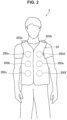
- FIG 2 is a diagram illustrating the exterior of the jacket 20.
- the jacket 20 includes a plurality of tactile stimulus units 200 and two sound output units 202 inside the jacket 20.
- a predetermined number of (for example, 6) tactile stimulus units 200 can be disposed on each of the front side and the rear side of the user.
- the individual tactile stimulus units 200 are disposed in a positional relation in which the individual tactile stimulus units 200 disposed on the front side mutually face the individual tactile stimulus units 200 disposed on the rear side.
- FIG 2 illustrates an example in which the jacket 20 is a sleeveless article, the present disclosure is not limited to this example and the jacket 20 may have sleeves.
- one or more tactile stimulus units 200 can also be disposed at positions corresponding to both arms of the user as well as the abdomen and the chest of the user.
- the tactile stimulus unit 200 outputs, for example, a tactile stimulus such as vibration in accordance with, for example, a control signal received from the server 10. Note that an example in which the tactile stimulus unit 200 generates vibration as a tactile stimulus will be mainly described below.
- the generated vibration can be perceived only in peripheral portions 210 of the tactile stimulus units 200, for example, as illustrated in FIG 3 . That is, in a case in which the individual tactile stimulus units 200 are disposed apart, the vibration generated independently by the individual tactile stimulus units 200 can be discretely perceived on the body of the user.
- a phantom sensation is an illusion phenomenon in which human beings perceive only one stimulus between presented stimulus positions when stimuli are simultaneously presented at different positions on skin.
- a position of the stimulus perceived by the user (hereinafter referred to as a perceptual position) is known to be a position between the two tactile stimulus units 200.
- FIG 5 is an explanatory diagram illustrating an example of a relation (an example of a phantom sensation) between perceptual positions and output intensities of two tactile stimulus units 200 in the situation illustrated in FIG 4 .
- an output intensity of the tactile stimulus unit 200a is successively weakened, such as "1,” “0.6,” and “0”
- an output intensity of the tactile stimulus unit 200b is successively strengthened, such as "0,” "0.6,” and “1” over time.
- a perceptual position 50 (perceived by the user) can be successively moved from a contact position of the tactile stimulus unit 200a to a contact position of the tactile stimulus unit 200b.
- the sound output unit 202 outputs a sound in accordance with a control signal received from, for example, the server 10. As illustrated in FIG 2 , one sound output unit 202 can be disposed on each of the right and left of the jacket 20. For example, the sound output units 202 are disposed to be located on or near the shoulder of the user when the user wears the jacket 20. However, the present disclosure is not limited to this example. In the jacket 20, only one sound output unit 202 may be disposed or three or more sound output units 202 may be disposed.
- the sound output unit 202 may be disposed as an independent device in a predetermined space or may be included in a mounting device (for example, a headphone, a headset, or the like) or a portable device (for example, a portable music player, a smartphone, a portable game device, or the like) different from the jacket 20.
- a mounting device for example, a headphone, a headset, or the like
- a portable device for example, a portable music player, a smartphone, a portable game device, or the like
- the display device 30 is a device that displays image information.
- the display device 30 projects the image information to a projection target 4 in accordance with a control signal received from the server 10, as will be described.
- the display device 30 may be a liquid crystal display (LCD) device, an organic light emitting diode (OLED) device, or the like.
- the display device 30 may be included in a portable device such as a tablet terminal or a smartphone or a mounting device such as an HMD or augmented reality (AR) glasses.
- the sound output units 202 and the display device 30 may be included in the same device.
- the server 10 is an example of an information processing device according to the present disclosure.
- the server 10 is a device that controls output of tactile stimuli to the plurality of tactile stimulus units 200 (or the jacket 20). For example, the server 10 controls generation of vibration on each of the plurality of tactile stimulus units 200 included in the jacket 20.
- the server 10 can also instruct the jacket 20 to generate vibration in each of the plurality of tactile stimulus units 200.
- the server 10 can have a function of controlling reproduction of content.
- content includes an image (image information) and a sound (sound information).
- the server 10 controls display of an image on the display device 30.
- the server 10 controls output of sounds to the sound output units 202.
- the user located within a predetermined space can simultaneously experience vibration generated by the plurality of tactile stimulus units 200, for example, while viewing a video display by the display device 30 and/or hearing music output by the sound output units 202.
- the server 10 can communicate with other devices (the tactile stimulus units 200, the sound output units 202, the display device 30, and the like) via the communication network 32 to be described below, for example,
- the communication network 32 is a wired or wireless transmission path of information transmitted from a device connected to the communication network 32.
- Examples of the communication network 32 may include a public line network such as a telephone network, the Internet, and a satellite communication network, various local area networks (LANs) including Ethernet (a registered trademark), and a wide area network (WAN). Further, the communication network 32 may include a dedicated network such as an Internet protocol-virtual private network (IP-VPN).
- IP-VPN Internet protocol-virtual private network
- an intensity at which the user actually perceives vibration by the tactile stimulus unit 200 (hereinafter referred to as a perceptual intensity) is lowered in accordance with a distance from the tactile stimulus unit 200.
- a perceptual intensity of vibration by the tactile stimulus unit 200 is lowered in inverse proportion to a distance from the tactile stimulus unit 200.
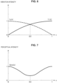
- FIG 6 is a graph illustrating a function f0(x) and a function f1(x) of output intensities of two tactile stimulus units 200 in the situation illustrated in FIG 4 according to the comparative example.
- the tactile stimulus unit 200a is caused to generate vibration with an output intensity like the function f0(x) illustrated in FIG 6 and the tactile stimulus unit 200a is simultaneously caused to generate vibration with an output intensity like the function f1(x) illustrated in FIG 6 .
- the function f0(x) and the function f1(x) are functions of adjusting the output intensity of the tactile stimulus unit 200 nonlinearly, a sensation of a perceptual position moving can be presented more strongly to the user due to the phantom sensation.
- the perceptual intensity may be considerably lowered compared to the two contact positions, as in the graph illustrated in FIG 7 . Therefore, in the comparative example, it is difficult to present a tactile stimulus with a desired perceptual intensity at a desired perceptual position to the user.
- the server 10 according to the embodiment was invented in view of the foregoing circumstances.
- the server 10 according to the embodiment changes output of one or more tactile stimulus units 200 corresponding to the predetermined positional information.
- the information regarding the tactile output includes, for example, a target perceptual intensity of a tactile stimulus or a (target) tactile output value.
- the server 10 can change the output intensity of one or more tactile stimulus units 200 in accordance with a position which is a tactile stimulus target and a target perceptual intensity at the position. Therefore, for example, the user can be caused to perceive a tactile stimulus (vibration or the like) so that the perceptual intensity is substantially constant between the contact positions of the plurality of tactile stimulus units 200.
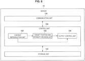
- FIG 8 is a functional block diagram illustrating a configuration example of the server 10 according to the embodiment.
- the server 10 includes a control unit 100, a communication unit 120, and a storage unit 122.
- the control unit 100 generally controls an operation of the server 10 using hardware such as a central processing unit (CPU) 150 or a random access memory (RAM) 154 to be described below contained in the server 10.
- the control unit 100 includes a content reproduction unit 102, a target position and intensity decision unit 104, and an output control unit 106.
- the content reproduction unit 102 controls reproduction of content. For example, in a case in which reproduction target content includes an image, the content reproduction unit 102 performs control of display of the image on the display device 30. In addition, in a case in which the reproduction target content includes a sound, the content reproduction unit 102 performs control of output of a sound on the sound output units 202.
- the content reproduction unit 102 can cause the display device 30 and/or the sound output units 202 to reproduce the reproduction target content in association with output control of a tactile stimulus by the output control unit 106 to be described below.
- the content reproduction unit 102 reproduces content in synchronization with timing of generation of vibration by one or more tactile stimulus units 200.
- a kind of reproduction target content may be decided on the basis of pre-decided setting information (a reproduction list or the like) or may be decided in response to a reproduction request input by the user.
- the target position and intensity decision unit 104 decides a target perceptual position of a tactile stimulus and a target perceptual intensity at the perceptual position at a predetermined timing.
- the target perceptual position can basically be set on the body of the user.
- the target position and intensity decision unit 104 decides a target perceptual position of a tactile stimulus and the target perceptual intensity at the perceptual position at a predetermined timing in accordance with reproduction target content.
- the target position and intensity decision unit 104 decides a target perceptual position and a target perceptual intensity at each timing in accordance with an image displayed and/or a sound output at each timing during a reproduction period of the reproduction target content.
- the target position and intensity decision unit 104 decides a target perceptual position at each timing during a reproduction period of the content on the basis of the target movement path.
- the target position and intensity decision unit 104 may decide a target perceptual position at a future predetermined timing in real time in accordance with a current (target) perceptual position and content which is currently being reproduced.
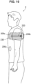
- FIG 9 is an explanatory diagram illustrating an example of a target movement path 220 set on the body of the user.
- FIG 9 illustrates an example in which the target movement path 220 is a path connecting a contact position of the tactile stimulus unit 200a, a contact position of the tactile stimulus unit 200c, a contact position of the tactile stimulus unit 200d, and a contact position of the tactile stimulus unit 200h.
- a tactile stimulus can be presented to the user so that the perceptual position is successively moved from the contact position of the tactile stimulus unit 200a which is a starting point to the contact position of the tactile stimulus unit 200h which is an ending point.
- the target movement path can be set as a path connecting a first surface of the body of the user, an inside of the body of the user, and a second surface opposite the first surface.
- the first surface can be a front surface of the user and the second surface can be the rear surface of the user.
- the first surface is a front side surface of a predetermined part of the body such as an arm and the second surface is a rear side surface of that part of the body.
- FIG 10 is an explanatory diagram illustrating another example of the target movement path 220.
- FIG 10 illustrates an example in which the target movement path 220 is a path connecting the contact position of the tactile stimulus unit 200a on the front surface of the user, an inside of the body of the user, and the contact position of the tactile stimulus unit 200b on the rear surface of the user.
- a sensation of piercing an inside of the body from the front surface to the rear surface can be presented to the user.
- the target position and intensity decision unit 104 can decide a set (region) of a target perceptual position at each timing during a reproduction period of the content on the basis of the target movement region.
- the target position and intensity decision unit 104 may decide a set of a target perceptual position at a future predetermined timing in real time in accordance with a set of a current (target) perceptual position and content which is currently being reproduced.
- the target movement region can be set as a region that spreads in area over time on the body of the user.
- FIG 11 is an explanatory diagram illustrating an example in which a target movement region 230 of a target perceptual position is set on the body of the user.
- FIG 11 illustrates an example in which the target movement region 230 is a region in which a set of the target perceptual positions spreads in area over time using the contact position of the tactile stimulus unit 200a as a starting point.
- the target movement region 230 is a region in which a distance between the contact position of the tactile stimulus unit 200a and the set of the target perceptual positions gradually increases over time.
- a tactile stimulus can be presented to the user so that a perceptual position successively spreads in area using the contact position of the tactile stimulus unit 200a which is a starting point as a reference.
- the contact position (that is, a starting point of the target movement region) of the tactile stimulus unit 200a is an example of a third position in the present disclosure.
- the target position and intensity decision unit 104 can decide a target perceptual intensity at each timing during the reproduction period of reproduction target content in accordance with the content.
- a target movement path (or a target movement region) can be associated with a target perceptual intensity at each position on the target movement path (or the target movement region) in advance.
- the target position and intensity decision unit 104 first decides a target movement path in accordance with, for example, the reproduction target content and decides a target perceptual intensity at each timing during a reproduction period of the content on the basis of the target movement path.
- the target perceptual intensity at each position on the target movement path (or the target movement region) may be decided all equally or may be decided differently for each position.
- the target perceptual intensity at each position on the target movement path (or the target movement region) may be set manually by the user.
- the target position and intensity decision unit 104 may decide the target perceptual intensity at a future predetermined timing in real time in accordance with a current (target) perceptual intensity and content which is currently being reproduced.
- a waveform of the target perceptual intensity can be registered in advance.
- the target position and intensity decision unit 104 can decide the target perceptual intensity at the target perceptual position, for example, in real time on the basis of the waveform of the target perceptual intensity and the decided target perceptual position.
- the waveform of the target perceptual intensity may be a constant function or may be registered in association with the reproduction target content.
- the output control unit 106 controls generation of vibration in the plurality of tactile stimulus units 200 corresponding to the target perceptual position in accordance with the target perceptual position and the target perceptual intensity decided by the target position and intensity decision unit 104. For example, the output control unit 106 first specifies the plurality of tactile stimulus units 200 (for example, three tactile stimulus units) located near the current target perceptual position. Then, the output control unit 106 decides an output intensity of each of the plurality of tactile stimulus units 200 on the basis of a positional relation between each of the plurality of tactile stimulus units 200 and the target perceptual position and the current target perceptual intensity. Thus, for example, the user can perceive vibration of the current target perceptual intensity at the current target perceptual position.
- the plurality of tactile stimulus units 200 for example, three tactile stimulus units
- the output control unit 106 sequentially adjusts the output intensity of each of the plurality of tactile stimulus units 200 corresponding to the changed target perceptual position.
- the output control unit 106 adjusts the output intensities of the plurality of corresponding tactile stimulus units 200 so that vibration of the same perceptual intensity is successively moved at each position on the target movement path 220 over time.
- the target movement path 220 is set as a movement path connecting the front surface and the rear surface of the body of the user.
- the output control unit 106 adjusts the output intensities of the plurality of corresponding tactile stimulus units 200 so that the perceptual position passes through an inside of the body along the target movement path 220 over time.
- the output control unit 106 adjusts the output intensities of the plurality of corresponding tactile stimulus units 200 so that the distance between the starting point (for example, the contact position of the tactile stimulus unit 200a) and the set (range) of the perceptual positions successively increases over time.
- the output control unit 106 adjusts the output intensities of the plurality of corresponding tactile stimulus units 200 so that the range 230 of the target perceptual position is successively moved along the target movement path 220.
- the output control unit 106 can change an output intensity of the tactile stimulus unit 200 (decided on the basis of the target perceptual intensity) on the basis of a distance between a target perceptual position and the tactile stimulus unit 200 located near the target perceptual position. For example, in a case in which the tactile stimulus unit 200a and the tactile stimulus unit 200b are located near the target perceptual position, the output control unit 106 changes the output intensity of the tactile stimulus unit 200a on the basis of a distance between the contact position of the tactile stimulus unit 200a on the body of the user and the target perceptual position.
- the output control unit 106 changes the output intensity of the tactile stimulus unit 200b on the basis of a distance between the contact position of the tactile stimulus unit 200b on the body of the user and the target perceptual position.
- the tactile stimulus unit 200a is an example of a first tactile stimulus unit according to the present disclosure
- the tactile stimulus unit 200b is an example of a second tactile stimulus unit according to the present disclosure.
- the output control unit 106 changes each of the output intensity of the tactile stimulus unit 200a and the output intensity of the tactile stimulus unit 200b on the basis of a positional relation between a middle position of the contact position of the tactile stimulus unit 200a and the contact position of the tactile stimulus unit 200b and the target perceptual position.
- the middle position is an example of a fourth position according to the present disclosure.
- the output control unit 106 may change the output intensities of the tactile stimulus unit 200a and the tactile stimulus unit 200b so that a sum value of the output intensity of the tactile stimulus unit 200a and the output intensity of the tactile stimulus unit 200b is larger as the distance between the middle position and the target perceptual position is smaller.
- the output control unit 106 may change the output intensity of the tactile stimulus unit 200a so that the output intensity of the tactile stimulus unit 200a is larger as a distance between the contact position of the tactile stimulus unit 200a and the target perceptual position is larger.
- the same applies to the tactile stimulus unit 200b that is, a reverse relation is satisfied).
- the output control unit 106 changes a ratio of the output intensity of the tactile stimulus unit 200a to the output intensity of the tactile stimulus unit 200b on the basis of the positional relation between the middle position and the target perceptual position.
- FIG 13 is an explanatory diagram illustrating an example of a scene in which the foregoing adjustment of the output intensities is applied and which corresponds to the example illustrated in FIG 5 .
- (a) and (c) of FIG 13 illustrate situation in which the target perceptual position 50 matches the contact position of the tactile stimulus unit 200a or the contact position of the tactile stimulus unit 200b.
- (b) of FIG 13 illustrates a timing at which the target perceptual position 50 is located at the middle position of the two tactile stimulus units 200.
- the output control unit 106 sets the output intensity of the tactile stimulus unit 200a to "1" and sets the output intensity of the tactile stimulus unit 200b to "0.”
- the output control unit 106 sets the output intensity of the tactile stimulus unit 200a to "1.5” and sets the output intensity of the tactile stimulus unit 200b to "1.5.”
- the output control unit 106 sets the output intensity of the tactile stimulus unit 200a to "0” and sets the output intensity of the tactile stimulus unit 200b to "1.” That is, the output control unit 106 adjusts the output intensities of the tactile stimulus unit 200a and the tactile stimulus unit 200b so that a sum of the output intensities of the two tactile stimulus units 200 is larger in a case in which the distance of the middle position of the two tactile stimulus units 200 and the target perceptual position 50 is small ((b) of FIG 13 ) than in a case in which
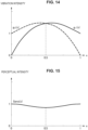
- the output control unit 106 obtains a function g0(x) illustrated in FIG 14 by multiplying the function f0(x) illustrated in FIG 6 by an adjustment function h0(x) as in the following Expression (1).
- the function g0(x) is a function indicating the output intensity of the tactile stimulus unit 200a in a case in which a target perceptual position is x.
- the output control unit 106 obtains a function g1(x) illustrated in FIG 14 by multiplying the function f1(x) illustrated in FIG 6 by an adjustment function h1(x) as in the following Expression (2).
- the function g1(x) is a function indicating the output intensity of the tactile stimulus unit 200b in a case in which the target perceptual position is x.
- the adjustment function h1(x) is a function that increases the output intensity of the tactile stimulus unit 200b in proportion to a distance between the tactile stimulus unit 200b and the target perceptual position.
- the function f0(x) and the function f1(x) are not limited to a square root function illustrated in FIG 6 and may be function of a logarithmic relation or linearity (a linear function or the like).
- g 1 x h 1 x ⁇ ⁇ 1 x
- FIG 15 illustrates a graph in a case in which the target perceptual intensity is set to "1" in an entire section between the two tactile stimulus units 200, vibration is generated in the tactile stimulus unit 200a using the function g0(x) illustrated in FIG 14 , and vibration is generated in the tactile stimulus unit 200b using the function g1(x) illustrated in FIG 14 .
- the perceptual intensity can be substantially constant in the entire section between the tactile stimulus unit 200a and the tactile stimulus unit 200b by applying the function g0(x) and the function g1(x). For example, even in a case in which the target perceptual position is located near the middle position, the perceptual intensity is not substantially lowered.
- the output control unit 106 changes the output intensities of the tactile stimulus units 200 on the basis of a distance between the contact position of the tactile stimulus unit 200 and the target perceptual position.
- FIG 16 illustrates an example in which a point A is a target perceptual position.
- the output control unit 106 (temporarily) calculates an output intensity of each of three tactile stimulus units 200 on the basis of a positional relation between contact positions (A0, A1, and A2) of the three tactile stimulus units 200 located near the point A. Then, with regard to each of the three tactile stimulus units 200, the output control unit 106 changes (corrects) the calculated output intensity on the basis of distance between the contact position of the tactile stimulus unit 200 and the target perceptual position (L0, L1, or L2 in the example illustrated in FIG 16 ).
- perceptual intensities (actually perceived by the user) at all the positions inside the triangle can be substantially constant. For example, even in a case in which the target perceptual position is located near the center of gravity of the triangle, the perceptual intensity is not substantially lowered.
- a triangle decided at contact positions (A0, A1, and A2) of three tactile stimulus units 200 located near a first target perceptual position (a point A) and a triangle decided at contact positions (A0, A2, and A3) of three tactile stimulus units 200 located near a second target perceptual position (a point B) may overlap each other.
- the output control unit 106 may set all the parameters of the foregoing adjustment function to be applied to the individual tactile stimulus units 200 to a predetermined value (the same value).
- the contact position of the tactile stimulus unit 200 on the body of the user is uncertain in some cases.
- the output control unit 106 may decide values of parameters of the adjustment function of the output intensities of the individual tactile stimulus units 200 on the assumption that the individual tactile stimulus units 200 are located at an equal interval.
- contact pressures of the tactile stimulus units 200 on the body of the user are uncertain in some cases.
- the output control unit 106 may set parameters of the adjustment function of the output intensities of the tactile stimulus units 200 to a predetermined value.
- the output control unit 106 can also change values of the parameters of the adjustment function of the output intensities of the tactile stimulus units 200 located near the corresponding tactile stimulus unit 200 (from values before the breakdown).
- the output control unit 106 can also change values of the parameters of the adjustment function of the output intensities of the tactile stimulus units 200 located near the corresponding tactile stimulus unit 200 (from values before the breakdown).
- the output control unit 106 may interrupt the generation of the vibration by all the tactile stimulus units 200.
- the output control unit 106 may interrupt the output of the tactile stimulus by the corresponding tactile stimulus unit 200 and may change the values of the parameters of the adjustment function of the output intensities of the tactile stimulus units 200 located near the corresponding tactile stimulus units 200 (from the values before the interruption).
- the output control unit 106 can further decide a movement speed of a target position.
- the output control unit 106 may set the movement speed of the target position to a predetermined value or may dynamically change the movement speed of the target position.
- the output control unit 106 may dynamically change the movement speed of the target position in accordance with reproduction target content (by the content reproduction unit 102).
- the output control unit 106 may change the movement speed of the target position on the basis of, for example, a rotational speed of the body of the user or a measurement result of a manipulation speed of the user on a predetermined device.
- the rotational speed of the body of the user can be specified on the basis of measurement decision by various sensors such as an acceleration sensor and a gyroscope carried or worn by the user.
- various sensors may be included in the jacket 20, may be included in the tactile stimulus units 200, or may be included in another device carried or worn by the user.
- a rotational speed of the body of the user may be specified by combining measurement results by other sensors (for example, the tactile stimulus units 200 include acceleration sensors, and the jacket 20 includes a gyroscope, and the like) included in other devices.
- the output control unit 106 may further dynamically change the output intensities of the plurality of tactile stimulus units 200 on the basis of a predetermined standard.
- the output control unit 106 can dynamically change the output intensities of the plurality of tactile stimulus units 200 on the basis of a perceptual position which is currently being moved (or a range of the perceptual position).
- the output control unit 106 relatively increases a target perceptual intensity in a range 240 of the perceptual position which is current being moved, while the range 230 of the target perceptual position is successively moved along the target movement path 220.
- the output control unit 106 can dynamically change the output intensities of the plurality of tactile stimulus units 200 on the basis of prediction of a movement direction of the perceptual position. For example, the output control unit 106 may relatively decrease the output intensities in a movement source or a movement destination of the perceptual position. Thus, contrast of the movement of the perceptual position can be emphasized and presented to the user.
- the output control unit 106 can dynamically change the output intensities of the plurality of tactile stimulus units 200 on the basis of a positional relation between a predetermined region and a perceptual position on the body of the user. For example, the output control unit 106 may control generation of vibration in the plurality of tactile stimulus units 200 so that the perceptual position is moved avoiding the predetermined region on the body of the user.
- the predetermined region can be, for example, a predetermined part near a heart or the like, a region in which an injury occurs, or the like.
- the output control unit 106 can also further dynamically change the output intensities of the plurality of tactile stimulus units 200 depending on parts including a target perceptual position. For example, in a case in which the target perceptual position is included in a part with high sensitivity, the output control unit 106 relatively weakens the output intensities of the plurality of tactile stimulus units 200. In addition, in a case in which the target perceptual position is included in a part with low sensitivity, the output control unit 106 relatively strengthens the output intensities of the plurality of tactile stimulus units 200.
- the output control unit 106 may change frequencies of vibration generated in the plurality of tactile stimulus units 200 (instead of the output intensities) depending on a part including the target perceptual position.
- frequencies of vibration generated in the plurality of tactile stimulus units 200 instead of the output intensities
- a desired perceptual intensity at the perceptual position can be presented to the user.
- the output control unit 106 can also further dynamically change the output intensities of the plurality of tactile stimulus units 200 in accordance with a movement speed of a target perceptual position. For example, the output control unit 106 dynamically changes a peak value (a maximum value) of the output intensities or change amounts of the output intensities of the plurality of tactile stimulus units 200. As one example, the output control unit 106 further decreases the maximum value of the output intensities or the change amounts of the output intensities as the movement speed of the target perceptual position is faster.
- the output control unit 106 may further dynamically change the output intensities of the individual tactile stimulus units 200 in accordance with the features of the individual tactile stimulus units 200.
- the output control unit 106 changes a ratio between the output intensities of the individual tactile stimulus units 200 in accordance with the features of the individual tactile stimulus units 200.
- the perceptual intensities of tactile stimuli can generally differ in accordance with contact pressures of the tactile stimulus units 200 on the body of the user.
- the output control unit 106 may further dynamically change the output intensities (values of the parameters of the adjustment function of the output intensities) of the individual tactile stimulus units 200 on the basis of a measurement result or an estimation result of the contact pressures of the individual tactile stimulus units 200.
- the contact pressures of the tactile stimulus units 200 can be measured or estimated in accordance with the following method. For example, in a case in which the tactile stimulus units 200 include pressure sensors, the contact pressures of the tactile stimulus units 200 can be measured by the pressure sensors.
- the contact pressure of the tactile stimulus unit 200 can be estimated on the basis of analysis of a change in a current value in the tactile stimulus unit 200.
- a relation between the contact pressure on a human body (or another object) and the current value in the tactile stimulus unit 200 can be obtained in advance by, for example, a developer.
- the contact pressure of the tactile stimulus unit 200 can be estimated on the basis of a measurement result of the current value in the tactile stimulus unit 200 and the measurement result.
- the contact pressures of the tactile stimulus units 200 can be estimated on the basis of attitudes of the tactile stimulus units 200 and/or the contact pressures of the tactile stimulus units 200.
- the attitudes of the tactile stimulus units 200 can be measured on the basis of, for example, gyroscopes and acceleration sensors contained in the tactile stimulus units 200.
- an attitude of the user can be measured on the basis of gyroscopes and acceleration sensors contained in another device carried or worn by the user.
- the communication unit 120 transmits and receives information to and from another device. For example, the communication unit 120 transmits a control signal of output of a tactile stimulus to each of the plurality of tactile stimulus units 200 (or the jacket 20) under the control of the output control unit 106. In addition, the communication unit 120 transmits a control signal of display of a reproduction target image to the display device 30 and transmits a control signal of output of a reproduction target sound to each of the plurality of sound output units 202 (or the jacket 20) under the control of the content reproduction unit 102.
- the storage unit 122 stores various kinds of data or various kinds of software.
- FIG 19 is a flowchart illustrating an operation example according to the embodiment.
- the target position and intensity decision unit 104 of the server 10 first decides a target perceptual position of a tactile stimulus and a target perceptual intensity at the perceptual position after a unit time ( ⁇ T seconds) of a current time in accordance with, for example, content or the like which is currently being reproduced (S101).
- the output control unit 106 specifies three tactile stimulus units 200 located near the target perceptual position (S103).
- the output control unit 106 performs "a process of calculating an output intensity" to be described below (S105).
- the output control unit 106 waits until ⁇ T seconds have passed from the time point of S101 (S107). Then, when ⁇ T seconds have passed (Yes in S107), the output control unit 106 causes a tactile stimulus with the output intensity calculated in S105 to be output to each of the three tactile stimulus units 200 (S109).
- the server 10 determines whether or not a predetermined ending condition is satisfied (S111). In a case in which the server 10 determines that the predetermined ending condition is not satisfied (No in S111), the server 10 performs the processes subsequent to S101 again. Conversely, in a case in which the server 10 determines that the predetermined ending condition is satisfied (Yes in S111), the server 10 ends the operation.
- the predetermined ending condition can be a condition that a predetermined time has passed from start of the operation, a condition that reproduction target content ends, or a condition that the user inputs an ending instruction.
- the output control unit 106 first sets "1" in a variable I indicating a numeral of a processing target tactile stimulus unit 200 among the three tactile stimulus units 200 specified in S103 (S151).
- the output control unit 106 repeats the process of the following S155 to S159 as long as the value of I is equal to or less than "3" (S153).
- the output control unit 106 first calculates an output intensity of an I-th tactile stimulus unit 200 (temporarily) on the basis of a positional relation between the target perceptual position decided in S101 and a contact position of each of the three tactile stimulus units 200 and the target perceptual intensity decided in S101 (S155).
- the output control unit 106 changes (corrects) the output intensity calculated in S155 on the basis of a distance between the target perceptual position and the contact position of the I-th tactile stimulus unit 200 (S157). Then, the output control unit 106 adds "1" to I (S159).
- the server 10 changes the output intensities of one or more tactile stimulus units 200 corresponding to predetermined positional information in accordance with the predetermined positional information on the body of the user and the target perceptual intensity of the tactile stimulus related to the positional information. Therefore, the user can be caused to perceive the tactile stimulus with an intensity adapted to the positional information on the body of the user. For example, the user can be caused to perceive a tactile stimulus (vibration or the like) so that the perceptual position is successively moved between the contact positions of the plurality of tactile stimulus units 200 and the perceptual intensity is substantially constant during the movement.
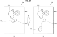
- FIG 21 is a diagram illustrating images 40 displayed by the display device 30 in Application Example 1.
- the images 40 are images (for example, 3-dimensional computer graphics (CG) images or the like) generated using a viewpoint of the user as a standard.
- the images 40 include ball type objects 400.
- the objects 400 are examples of target regions according to the present disclosure.
- the output control unit 106 first specifies a position (collision position) on the body of the user corresponding to the position of the object 400a in the image 40b illustrated in (b) of FIG 21 .
- the collision position is near the contact position of a tactile stimulus unit 200e.
- the output control unit 106 controls output of the tactile stimuli to the plurality of tactile stimulus units 200 located nearby such that, for example, a set 230 of target perceptual positions spreads in area from a specific position serving as a starting point over time.
- a sensation of propagating an impact to the vicinity from the collision position serving as a starting point can be presented to the user.
- the content reproduction unit 102 causes the two sound output units 202 to output impact sounds as an impact sound is coming from the collision position on the body of the user, as indicated by two dotted-line curves in FIG 22 .
- the content reproduction unit 102 causes the sound output unit 202b on the left side of the body of the user to output the impact sound with a larger volume and causes the sound output unit 202a on the right side of the body of the user to output the impact sound with a smaller volume.
- the video in which the ball is hit on the body of the user can be displayed and a tactile stimulus and an acoustic sound optimum for the video can be simultaneously presented to the user.
- a tactile stimulus and an acoustic sound optimum for the video can be simultaneously presented to the user.
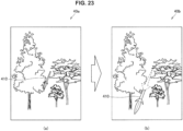
- FIG 23 is a diagram illustrating another example of the images 40 displayed by the display device 30.
- the images 40 include a spear type object 410.
- the object 410 is an example of a target region according to the present disclosure.
- the target position and intensity decision unit 104 first decides a movement path 220 of a target perceptual position on the basis of a movement trajectory of the object 410 in the image 40.
- the target position and intensity decision unit 104 first specifies a position (collision position) on the body of the user corresponding to the position of the front tip of the object 410 in the image 40b illustrated in FIG 23 . Note that in the example illustrated in FIG 25 , the collision position is near the contact position of the tactile stimulus unit 200e. Then, the target position and intensity decision unit 104 decides the movement path 220 of the target perceptual position on the basis of the specified position and the movement trajectory of the object 410 in the image 40.
- the movement path 220 of the target perceptual position is a path connecting a position near the tactile stimulus unit 200e located on the front surface of the left side of the user and a position near a tactile stimulus unit 200i located on the rear surface of the left side of the user. Further, the target position and intensity decision unit 104 decides the range 230 of the target perceptual position.
- the output control unit 106 controls output of tactile stimuli to the plurality of tactile stimulus units 200 such as the tactile stimulus unit 200e and the tactile stimulus unit 200i such that the user can perceive successive movement of the range 230 of the target perceptual position along the movement path 220 of the target perceptual position.
- a sensation of being pierced by a spear from the front left to the rear left of the user from the collision position serving as a starting point can be presented to the user.
- the content reproduction unit 102 causes the two sound output units 202 to output impact sounds as an impact sound is coming from the collision position on the body of the user, as indicated by two dotted-line curves in FIG 25 .
- the content reproduction unit 102 causes the sound output unit 202b on the left side of the body of the user to output the impact sound with a larger volume and causes the sound output unit 202a on the right side of the body of the user to output the impact sound with a smaller volume.
- the video in which the spear pierces the body of the user can be displayed and a tactile stimulus and an acoustic sound optimum for the video can be simultaneously presented to the user.
- a tactile stimulus and an acoustic sound optimum for the video can be simultaneously presented to the user.
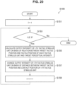
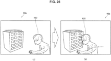
- FIG 26 is a diagram illustrating still another example of the images 40 displayed by the display device 30.
- the images 40 include a monster object 420.
- the object 420 is an example of a target region according to the present disclosure.
- the output control unit 106 first specifies a position (collision position) on the body of the user corresponding to the position of the object 420 (for example, a position of a hand of the object 420 or the like) in the image 40a illustrated in FIG 26 .
- the collision position is near the contact position of a tactile stimulus unit 200a.
- the target position and intensity decision unit 104 decides the movement path 220 of the target perceptual position on the basis of the specified position and the movement trajectory (attack trajectory) of the object 420 in the image 40.
- the movement path 220 of the target perceptual position is a path connecting the vicinity of the contact position of the tactile stimulus unit 200a located on the right side of the user and the vicinity of the contact position of the tactile stimulus unit 200b located on the left side of the user.
- the target position and intensity decision unit 104 decides the range 230 of the target perceptual position.
- the output control unit 106 controls output of tactile stimuli to the plurality of tactile stimulus units 200 such as the tactile stimulus unit 200a and the tactile stimulus unit 200e such that the user can perceive successive movement of the range 230 of the target perceptual position along the movement path 220 of the target.
- a sensation of being attacked by the object 420 from the right side to the left side of the user from the collision position serving as a starting point can be presented to the user.
- the content reproduction unit 102 causes the two sound output units 202 to output an impact sound so that the impact sound is moved along a movement trajectory 250 of the impact sound and is heard over time, as indicated by a dotted-line curve in FIG 27 .
- the impact sound can be output in conjunction with the movement of the perceptual position along the movement path 220.
- the content reproduction unit 102 causes a ratio of a volume of the impact sound caused to be output by the sound output unit 202a on the right side of the body of the user to a volume of the impact sound caused to be output by the sound output unit 202b on the left side of the body of the user to be changed with the movement of the target perceptual position.
- the video in which the object 420 attacks the user from the right side to the left side can be displayed and a tactile stimulus and an acoustic sound optimum for the video can be simultaneously presented to the user.
- a tactile stimulus and an acoustic sound optimum for the video can be simultaneously presented to the user.
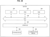
- the server 10 include a CPU 150, a read only memory (ROM) 152, a RAM 154, a bus 156, an interface 158, a storage device 160 and a communication device 162.
- ROM read only memory
- RAM random access memory
- bus 156 a bus 156
- interface 158 a storage device 160
- communication device 162 a communication device 162.
- the CPU 150 which functions as an arithmetic processing unit and a control device, controls the whole operation within the server 10 in accordance with various kinds of programs. Further, the CPU 150 implements a function of the control unit 100 at the server 10. Note that the CPU 150 includes a processor such as a microprocessor.
- the ROM 152 stores programs, control data such as an operation parameter, or the like, to be used by the CPU 150.
- the RAM 154 temporarily stores, for example, programs to be executed by the CPU 150.
- the bus 156 includes a CPU bus, or the like.
- the bus 156 interconnects the CPU 150, the ROM 152 and the RAM 154.
- the interface 158 connects the storage device 160 and the communication device 162 to the internal bus 156.
- the storage device 160 is a device for data storage, which functions as the storage unit 122.
- the storage device 160 includes, for example, a storage medium, a recording device which records data in the storage medium, a readout device which reads out data from the storage medium, a deletion device which deletes data recorded in the storage medium, or the like.
- the communication device 162 is a communication interface including a communication device, or the like, for connecting to, for example, the communication network 32, or the like. Further, the communication device 162 may be a communication device supporting a wireless LAN, a communication device supporting long term evolution (LTE) or a wired communication device which performs communication in a wired manner. The communication device 162 functions as the communication unit 120.
- LTE long term evolution
- the target perceptual position can be located outside of a presentation range of the tactile stimuli by all the tactile stimulus units 200 in some cases.
- a distance between the disposition positions of the tactile stimulus units 200 is considerably large, it is difficult to allow the user to perceive tactile stimuli with a target perceptual intensity in a range between the plurality of tactile stimulus units 200 in some cases.
- the server 10 may cause content which is being reproduced to be changed so that a sensation (illusion) of moving the perceptual position outside of the presentation range is given to the user.
- the server 10 causes an image which is being displayed (or a specific region inside an image) in the same direction as a movement direction of the target perceptual position (for example, as described in "3. Application Example") to be moved or causes a ratio between volumes caused to be output to the right and left of the body of the user to be changed.
- the server 10 sets output intensities of one or more corresponding tactile stimulus units 200 to be the same as output intensities of a case in which the target perceptual position is located in the boundary of the range or weakens the output intensities in accordance with a distance between the target perceptual position and the boundary.
- the server 10 may control the plurality of tactile stimulus units 200 such that the tactile stimuli are sequentially output from the upper side to the lower side or from the lower side to the upper side along the arrangement in the upper and lower directions (the vertical direction) of the plurality of tactile stimulus units 200 on the body of the user.
- a gravity sensation, a moving-up sensation, or a moving-down sensation can be presented to the user.
- the user can expect to obtain a sensation of taking a moving elevator.
- the server 10 may control output of tactile stimuli to the plurality of tactile stimulus units 200 such that a sensation of pulling the body (for example, a skin or the like) is presented to the user.
- the server 10 may control output of tactile stimuli in one or more tactile stimulus units 200 and/or the plurality of tactile stimulus units 200 included in the jacket 20 in accordance with a user manipulation (shaking, rotating, or the like) on a predetermined casing including the one or more tactile stimulus units 200.
- a user manipulation shaking, rotating, or the like
- the server 10 can also control output of tactile stimuli to the plurality of tactile stimulus units 200 such that an illusion of orienting a perceptual position between the plurality of tactile stimulus units 200 is presented to the user.
- the output control unit 106 may sequentially change output intensities of two tactile stimulus units 200 so that a perceptual position reciprocates between the two tactile stimulus units 200 (in particular, the perceptual position reciprocates near a middle position) at a short period.
- the output control unit 106 may first change output intensities of two tactile stimulus units 200 so that a perceptual position is moved from the contact position of one of the two tactile stimulus units 200 to the middle position and may then hold (fix) the output intensities of the two tactile stimulus units 200 as the same value after the perceptual position reaches the middle position.
- the output control unit 106 may set the output intensity of one of the two tactile stimulus units 200 to "0" or a predetermined small value or may gradually decrease the output intensity of the tactile stimulus unit 200. In such a control example, the user can expect to obtain a sensation of orienting the perceptual position in the middle of the two tactile stimulus units 200.
- an amplitude of a waveform of the output intensity of the tactile stimulus unit 200 (decided on the basis of a waveform of a target perceptual intensity) can be adjusted so that a maximum value of the output intensity (amplitude) is equal to or less than a predetermined value.
- the amplitude of the waveform of the output intensity can be adjusted so that the maximum value of the amplitude is equal to or less than the predetermined value.
- the amplitude of the waveform of the output intensity may be adjusted in advance or may be adjusted in real time.
- the values of the parameters of the adjustment function of the output intensity (as described above) may be adjusted so that the maximum value of the amplitude is equal to or less than the predetermined value.
- the perceptual intensity of the tactile stimulus can generally differ depending on a frequency of vibration.
- human beings can feel vibration most strongly in a case in which a frequency of vibration is about 200 Hz and can feel vibration more weakly when the frequency is higher than 200 Hz.
- the output control unit 106 may change the frequency of the vibration caused to be generated by the plurality of tactile stimulus units 200 (instead of changing the amplitude) on the basis of the target perceptual position and the target perceptual intensity.
- a tactile stimulus of a target perceptual intensity at a target perceptual position can be presented to the user (as in the case in which the amplitude is changed).
- the tactile stimulus units 200 may output temperature, force sense information, electric stimuli, or the like as tactile stimuli.
- the user 10 can present a target temperature at a position between the plurality of tactile stimulus units 200 by adjusting the temperature of each of the plurality of tactile stimulus units 200 disposed away from the body of the user.
- the server 10 can present a target perceptual intensity at the position between the plurality of tactile stimulus units 200 by adjusting strength of the force sense information caused to be output by the plurality of tactile stimulus units 200.
- the server 10 can present the target perceptual intensity at the position between the plurality of tactile stimulus units 200 by adjusting strength of electric stimuli caused to be output by the plurality of tactile stimulus units 200.
- the positional information according to the present disclosure is the positional information on the body of the user has been mainly described, but the present disclosure is not limited to this example, but the positional information may be spatial positional information.
- the positional information can be positional information in an actual space. In this case, a target perceptual position (or a region of the target perceptual position, a path of the target perceptual position, or the like) in the actual space can be set.
- the server 10 may cause the plurality of tactile stimulus units 200 to generate vibration or may change an output intensity of vibration of each of the plurality of tactile stimulus units 200.
- the positional information can be positional information in a virtual space.
- a target perceptual position or a region of the target perceptual position, a path of the target perceptual position, or the like
- the server 10 may cause the plurality of tactile stimulus units 200 to generate vibration or may change an output intensity of vibration of each of the plurality of tactile stimulus units 200.
- the information processing device may be a personal computer (PC), a tablet terminal, a portable telephone such as a smartphone, a game device, a portable music player, a mounting device such as an HMD or a wrist type device, or the jacket 20.
- PC personal computer
- tablet terminal a portable telephone such as a smartphone
- game device such as a smartphone
- portable music player such as a portable music player
- mounting device such as an HMD or a wrist type device, or the jacket 20.
- the example in which the tactile stimulus units according to the present disclosure are included in the jacket 20 has been mainly described, but the present disclosure is not limited to the example.
- the tactile stimulus units may be included another kind of device.
- the tactile stimulus units may be included in a write watch type device or a wrist type device or may be included in a chair.
- each step in the operation of each embodiment described above may not necessarily have to be processed in the described sequence.
- each step may be processed in a suitably changed sequence.
- some each of the steps may be processed in parallel or individually.
- some of the described steps may be omitted or another step may be further added to the described steps.
Description
- The present disclosure relates to an information processing device, an information processing method, and a program.
- In the related art, for example, various technologies for presenting tactile stimuli such as vibration to users have been proposed.
- For example,
Patent Literature 1 discloses a technology for outputting a tactile stimulus to a predetermined device in a case in which an event occurs in a virtual space. -
Patent Literature 2 discloses that a first oscillator is mounted on the abdominal part of a subject and a second oscillator is mounted on the back part of the subject. A drive signal generator 3 generates first and second drive signals S1 and S2. The first and second drive signals S1 and S2 drive first andsecond oscillators second oscillator 2. After the first oscillation duration D1 is over, the second oscillation duration D2 is over. -
- Patent Literature 1:
JP 2015-166890A - Patent Literature 2:
JP 2009-070263 (A - Incidentally, for example, a tactile stimulus to be output preferably differs depending on a position or the like which is a tactile stimulus target. However, in the technology disclosed in
Patent Literature 1, the same tactile stimulus is output regardless of positional information. - Accordingly, the present disclosure proposes a novel and improved information processing device, a novel and improved information processing method, and a novel and improved program capable of changing an output of a tactile stimulus adaptively to positional information.
- According to the present disclosure, there is provided an information processing device, an information processing method, and a computer program as defined in the appended set of claims.
- According to the present disclosure, as described above, it is possible to change an output of a tactile stimulus adaptively to positional information. Further, the effect described here is not necessarily limiting, and any effect described in the present disclosure may be included.
-
- [
FIG 1] FIG 1 is an explanatory diagram illustrating a configuration example of an information processing system according to an embodiment of the present disclosure. - [
FIG. 2] FIG 2 is an exterior view illustrating ajacket 20 according to the embodiment. - [
FIG 3] FIG 3 is an explanatory diagram illustrating ranges in which tactile stimuli can be presented alone by individual tactile stimulus units 200. - [
FIG 4] FIG 4 is an explanatory diagram illustrating an example in which two tactile stimulus units 200 are disposed on the body of a user. - [
FIG 5] FIG 5 is an explanatory diagram illustrating an example of a relation between perceptual positions and output intensities of two tactile stimulus units 200 in a situation illustrated inFIG 4 . - [
FIG 6] FIG 6 is a graph illustrating a relation between a perceptual position and an output intensity set in each of two tactile stimulus units 200 according to a comparative example of the present disclosure. - [
FIG 7] FIG 7 is a graph illustrating a relation between a perceptual position and a perceptual intensity in a case in which a function illustrated inFIG 6 is applied. - [
FIG 8] FIG 8 is a functional block diagram illustrating a configuration example of aserver 10 according to the embodiment. - [
FIG 9] FIG 9 is an explanatory diagram illustrating an example of amovement path 220 of a target perceptual position set on the body of the user. - [
FIG 10] FIG 10 is an explanatory diagram illustrating another example of themovement path 220 of the target perceptual position. - [
FIG 11] FIG 11 is an explanatory diagram illustrating an example in which arange 230 of a target perceptual position is enlarged. - [
FIG 12] FIG 12 is an explanatory diagram illustrating an example in which therange 230 of the target perceptual position is successively moved along thetarget movement path 220. - [
FIG 13] FIG 13 is an explanatory diagram illustrating an example in which an output intensity adjustment function according to the embodiment is applied in the situation illustrated inFIG 4 . - [
FIG 14] FIG 14 is an explanatory diagram illustrating an example of an output intensity adjustment function according to the embodiment. - [
FIG 15] FIG 15 is a graph illustrating a relation between a perceptual position and a perceptual intensity in a case in which the function illustrated inFIG 15 is applied. - [
FIG 16] FIG 16 is an explanatory diagram illustrating a planar adjustment example of output intensities of a plurality of tactile stimulus units 200. - [
FIG 17] FIG 17 is an explanatory diagram illustrating an example in which triangles configured with regard to two target perceptual positions overlap. - [
FIG 18] FIG 18 is an explanatory diagram illustrating an example in which arange 240 of a perceptual position which is currently moving is emphatically vibrated. - [
FIG 19] FIG 19 is a flowchart illustrating an overall flow of an operation example according to the embodiment. - [
FIG 20] FIG 20 is a flowchart illustrating a flow of an "output intensity calculation process" according to the embodiment. - [
FIG 21] FIG 21 is adiagram illustrating images 40 displayed in Application Example 1 of the embodiment. - [
FIG 22] FIG 22 is a schematic diagram illustrating a tactile stimulus and a sound output to the user in Application Example 1. - [
FIG 23] FIG 23 is adiagram illustrating images 40 displayed in Application Example 2 of the embodiment. - [
FIG 24] FIG 24 is a schematic diagram illustrating a movement path of a perceptual position of a tactile stimulus output in Application Example 2. - [
FIG 25] FIG 25 is a schematic diagram illustrating a tactile stimulus and a sound output to a user in Application Example 2. - [
FIG 26] FIG 26 is adiagram illustrating images 40 displayed in Application Example 3 of the embodiment. - [
FIG 27] FIG 27 is a schematic diagram illustrating a tactile stimulus and a sound output to a user in Application Example 3. - [
FIG 28] FIG 28 is an explanatory diagram illustrating a hardware configuration example of theserver 10 according to the embodiment. - Hereinafter, (a) preferred embodiment(s) of the present disclosure will be described in detail with reference to the appended drawings. Note that, in this specification and the appended drawings, structural elements that have substantially the same function and structure are denoted with the same reference numerals, and repeated explanation of these structural elements is omitted.
- Further, in this specification and the drawings, a plurality of constituent elements having substantially the same functional configuration are also distinguished by attaching different letters after the same reference numerals. For example, a plurality of components having substantially the same functional configuration are distinguished like a server 10a and a server 10b if necessary. Here, in a case in which it is not necessary to particularly distinguish each of a plurality of constituent elements having substantially the same functional configuration, only the same reference numerals are attached. For example, in a case in which it is not necessary to particularly distinguish the server 10a and the server 10b from each other, they are simply referred to as a
server 10. - In addition, the items of "Mode(s) for Carrying Out the Invention" will be described in the following order.
- 1. Configuration of information processing system
- 2. Detailed description of embodiment
- 3. Application examples
- 4. Hardware configuration
- 5. Modification example
- First, a configuration of an information processing system according to an embodiment of the present disclosure will be described with reference to
FIG 1. FIG 1 is an explanatory diagram illustrating the configuration of the information processing system according to the embodiment. As illustrated inFIG 1 , the information processing system includes aserver 10, adisplay device 30, and acommunication network 32. In addition, in the embodiment, as illustrated inFIG 1 , auser 2 can wear ajacket 20 to be described below. -
FIG 2 is a diagram illustrating the exterior of thejacket 20. As illustrated inFIG 2 , thejacket 20 includes a plurality of tactile stimulus units 200 and two sound output units 202 inside thejacket 20. For example, inside thejacket 20, a predetermined number of (for example, 6) tactile stimulus units 200 can be disposed on each of the front side and the rear side of the user. For example, the individual tactile stimulus units 200 are disposed in a positional relation in which the individual tactile stimulus units 200 disposed on the front side mutually face the individual tactile stimulus units 200 disposed on the rear side. Note that, althoughFIG 2 illustrates an example in which thejacket 20 is a sleeveless article, the present disclosure is not limited to this example and thejacket 20 may have sleeves. In this case, one or more tactile stimulus units 200 can also be disposed at positions corresponding to both arms of the user as well as the abdomen and the chest of the user. - The tactile stimulus unit 200 outputs, for example, a tactile stimulus such as vibration in accordance with, for example, a control signal received from the
server 10. Note that an example in which the tactile stimulus unit 200 generates vibration as a tactile stimulus will be mainly described below. - Incidentally, in a case in which the plurality of tactile stimulus units 200 included in the
jacket 20 each generate vibration alone, the generated vibration can be perceived only in peripheral portions 210 of the tactile stimulus units 200, for example, as illustrated inFIG 3 . That is, in a case in which the individual tactile stimulus units 200 are disposed apart, the vibration generated independently by the individual tactile stimulus units 200 can be discretely perceived on the body of the user. - On the other hand, an illusion sensation such as a phantom sensation has been medically elucidated. A phantom sensation is an illusion phenomenon in which human beings perceive only one stimulus between presented stimulus positions when stimuli are simultaneously presented at different positions on skin. For example, as illustrated in
FIG 4 , when a stimulus is caused to be simultaneously output to two tactile stimulus units 200 disposed on the body of the user, a position of the stimulus perceived by the user (hereinafter referred to as a perceptual position) is known to be a position between the two tactile stimulus units 200. -
FIG 5 is an explanatory diagram illustrating an example of a relation (an example of a phantom sensation) between perceptual positions and output intensities of two tactile stimulus units 200 in the situation illustrated inFIG 4 . For example, as illustrated inFIG 5 , it is assumed that, for example, an output intensity of thetactile stimulus unit 200a is successively weakened, such as "1," "0.6," and "0," and an output intensity of thetactile stimulus unit 200b is successively strengthened, such as "0," "0.6," and "1" over time. In this case, as illustrated inFIG 5 , a perceptual position 50 (perceived by the user) can be successively moved from a contact position of thetactile stimulus unit 200a to a contact position of thetactile stimulus unit 200b. By changing the output intensities of the plurality of tactile stimulus units 200 in this way, it is possible to successively expand a range of a tactile stimulus which can be presented by the plurality of tactile stimulus units 200 without changing a disposition interval of the individual tactile stimulus units 200. - The sound output unit 202 outputs a sound in accordance with a control signal received from, for example, the
server 10. As illustrated inFIG 2 , one sound output unit 202 can be disposed on each of the right and left of thejacket 20. For example, the sound output units 202 are disposed to be located on or near the shoulder of the user when the user wears thejacket 20. However, the present disclosure is not limited to this example. In thejacket 20, only one sound output unit 202 may be disposed or three or more sound output units 202 may be disposed. In addition, instead of being included in thejacket 20, the sound output unit 202 may be disposed as an independent device in a predetermined space or may be included in a mounting device (for example, a headphone, a headset, or the like) or a portable device (for example, a portable music player, a smartphone, a portable game device, or the like) different from thejacket 20. - The
display device 30 is a device that displays image information. For example, thedisplay device 30 projects the image information to aprojection target 4 in accordance with a control signal received from theserver 10, as will be described. Note that, although thedisplay device 30 is illustrated as an example of a projector inFIG 1 , the present disclosure is not limited to this example. Thedisplay device 30 may be a liquid crystal display (LCD) device, an organic light emitting diode (OLED) device, or the like. In addition, thedisplay device 30 may be included in a portable device such as a tablet terminal or a smartphone or a mounting device such as an HMD or augmented reality (AR) glasses. In addition, in this case, the sound output units 202 and thedisplay device 30 may be included in the same device. - The
server 10 is an example of an information processing device according to the present disclosure. Theserver 10 is a device that controls output of tactile stimuli to the plurality of tactile stimulus units 200 (or the jacket 20). For example, theserver 10 controls generation of vibration on each of the plurality of tactile stimulus units 200 included in thejacket 20. Alternatively, in a case in which thejacket 20 has a function of controlling the plurality of tactile stimulus units 200, theserver 10 can also instruct thejacket 20 to generate vibration in each of the plurality of tactile stimulus units 200. - In addition, the
server 10 can have a function of controlling reproduction of content. Here, content includes an image (image information) and a sound (sound information). For example, theserver 10 controls display of an image on thedisplay device 30. In addition, theserver 10 controls output of sounds to the sound output units 202. Thus, the user located within a predetermined space can simultaneously experience vibration generated by the plurality of tactile stimulus units 200, for example, while viewing a video display by thedisplay device 30 and/or hearing music output by the sound output units 202. - In addition, the
server 10 can communicate with other devices (the tactile stimulus units 200, the sound output units 202, thedisplay device 30, and the like) via thecommunication network 32 to be described below, for example, - The
communication network 32 is a wired or wireless transmission path of information transmitted from a device connected to thecommunication network 32. Examples of thecommunication network 32 may include a public line network such as a telephone network, the Internet, and a satellite communication network, various local area networks (LANs) including Ethernet (a registered trademark), and a wide area network (WAN). Further, thecommunication network 32 may include a dedicated network such as an Internet protocol-virtual private network (IP-VPN). - The configuration of the information processing system according to the embodiment has been described above. Incidentally, an intensity at which the user actually perceives vibration by the tactile stimulus unit 200 (hereinafter referred to as a perceptual intensity) is lowered in accordance with a distance from the tactile stimulus unit 200. For example, a perceptual intensity of vibration by the tactile stimulus unit 200 is lowered in inverse proportion to a distance from the tactile stimulus unit 200.
- Here, a comparative example of the present disclosure will be described.
FIG 6 is a graph illustrating a function f0(x) and a function f1(x) of output intensities of two tactile stimulus units 200 in the situation illustrated inFIG 4 according to the comparative example. In the comparative example, thetactile stimulus unit 200a is caused to generate vibration with an output intensity like the function f0(x) illustrated inFIG 6 and thetactile stimulus unit 200a is simultaneously caused to generate vibration with an output intensity like the function f1(x) illustrated inFIG 6 . Since the function f0(x) and the function f1(x) are functions of adjusting the output intensity of the tactile stimulus unit 200 nonlinearly, a sensation of a perceptual position moving can be presented more strongly to the user due to the phantom sensation. - However, in this case, near a middle of a contact position of the
tactile stimulus unit 200a and a contact position of thetactile stimulus unit 200b, the perceptual intensity may be considerably lowered compared to the two contact positions, as in the graph illustrated inFIG 7 . Therefore, in the comparative example, it is difficult to present a tactile stimulus with a desired perceptual intensity at a desired perceptual position to the user. - Accordingly, the
server 10 according to the embodiment was invented in view of the foregoing circumstances. In accordance with predetermined positional information on the body of the user and information regarding tactile output related to the predetermined positional information, theserver 10 according to the embodiment changes output of one or more tactile stimulus units 200 corresponding to the predetermined positional information. Here, the information regarding the tactile output includes, for example, a target perceptual intensity of a tactile stimulus or a (target) tactile output value. - For example, the
server 10 can change the output intensity of one or more tactile stimulus units 200 in accordance with a position which is a tactile stimulus target and a target perceptual intensity at the position. Therefore, for example, the user can be caused to perceive a tactile stimulus (vibration or the like) so that the perceptual intensity is substantially constant between the contact positions of the plurality of tactile stimulus units 200. - Next, a configuration of the
server 10 according to the embodiment will be described in detail.FIG 8 is a functional block diagram illustrating a configuration example of theserver 10 according to the embodiment. As illustrated inFIG. 8 , theserver 10 includes acontrol unit 100, acommunication unit 120, and astorage unit 122. - The
control unit 100 generally controls an operation of theserver 10 using hardware such as a central processing unit (CPU) 150 or a random access memory (RAM) 154 to be described below contained in theserver 10. In addition, as illustrated inFIG 8 , thecontrol unit 100 includes acontent reproduction unit 102, a target position andintensity decision unit 104, and anoutput control unit 106. - The
content reproduction unit 102 controls reproduction of content. For example, in a case in which reproduction target content includes an image, thecontent reproduction unit 102 performs control of display of the image on thedisplay device 30. In addition, in a case in which the reproduction target content includes a sound, thecontent reproduction unit 102 performs control of output of a sound on the sound output units 202. - In addition, the
content reproduction unit 102 can cause thedisplay device 30 and/or the sound output units 202 to reproduce the reproduction target content in association with output control of a tactile stimulus by theoutput control unit 106 to be described below. For example, thecontent reproduction unit 102 reproduces content in synchronization with timing of generation of vibration by one or more tactile stimulus units 200. - Note that a kind of reproduction target content may be decided on the basis of pre-decided setting information (a reproduction list or the like) or may be decided in response to a reproduction request input by the user.
- The target position and
intensity decision unit 104 decides a target perceptual position of a tactile stimulus and a target perceptual intensity at the perceptual position at a predetermined timing. Here, the target perceptual position can basically be set on the body of the user. For example, the target position andintensity decision unit 104 decides a target perceptual position of a tactile stimulus and the target perceptual intensity at the perceptual position at a predetermined timing in accordance with reproduction target content. As one example, the target position andintensity decision unit 104 decides a target perceptual position and a target perceptual intensity at each timing in accordance with an image displayed and/or a sound output at each timing during a reproduction period of the reproduction target content. - For example, in a case in which a target movement path is associated with reproduction target content in advance, the target position and
intensity decision unit 104 decides a target perceptual position at each timing during a reproduction period of the content on the basis of the target movement path. Alternatively, the target position andintensity decision unit 104 may decide a target perceptual position at a future predetermined timing in real time in accordance with a current (target) perceptual position and content which is currently being reproduced. - Here, the target movement path can be set on the surface of the body of the user.
FIG 9 is an explanatory diagram illustrating an example of atarget movement path 220 set on the body of the user.FIG 9 illustrates an example in which thetarget movement path 220 is a path connecting a contact position of thetactile stimulus unit 200a, a contact position of thetactile stimulus unit 200c, a contact position of thetactile stimulus unit 200d, and a contact position of thetactile stimulus unit 200h. In this case, a tactile stimulus can be presented to the user so that the perceptual position is successively moved from the contact position of thetactile stimulus unit 200a which is a starting point to the contact position of thetactile stimulus unit 200h which is an ending point. - Alternatively, the target movement path can be set as a path connecting a first surface of the body of the user, an inside of the body of the user, and a second surface opposite the first surface. Here, the first surface can be a front surface of the user and the second surface can be the rear surface of the user. Alternatively, for example, the first surface is a front side surface of a predetermined part of the body such as an arm and the second surface is a rear side surface of that part of the body.
FIG 10 is an explanatory diagram illustrating another example of thetarget movement path 220.FIG 10 illustrates an example in which thetarget movement path 220 is a path connecting the contact position of thetactile stimulus unit 200a on the front surface of the user, an inside of the body of the user, and the contact position of thetactile stimulus unit 200b on the rear surface of the user. In this case, a sensation of piercing an inside of the body from the front surface to the rear surface can be presented to the user. - In addition, in a case in which a target movement region is associated with reproduction target content in advance, the target position and
intensity decision unit 104 can decide a set (region) of a target perceptual position at each timing during a reproduction period of the content on the basis of the target movement region. Alternatively, the target position andintensity decision unit 104 may decide a set of a target perceptual position at a future predetermined timing in real time in accordance with a set of a current (target) perceptual position and content which is currently being reproduced. - Here, the target movement region can be set as a region that spreads in area over time on the body of the user.
FIG 11 is an explanatory diagram illustrating an example in which atarget movement region 230 of a target perceptual position is set on the body of the user.FIG 11 illustrates an example in which thetarget movement region 230 is a region in which a set of the target perceptual positions spreads in area over time using the contact position of thetactile stimulus unit 200a as a starting point. For example, thetarget movement region 230 is a region in which a distance between the contact position of thetactile stimulus unit 200a and the set of the target perceptual positions gradually increases over time. In this case, a tactile stimulus can be presented to the user so that a perceptual position successively spreads in area using the contact position of thetactile stimulus unit 200a which is a starting point as a reference. Note that the contact position (that is, a starting point of the target movement region) of thetactile stimulus unit 200a is an example of a third position in the present disclosure. - In addition, the target position and
intensity decision unit 104 can decide a target perceptual intensity at each timing during the reproduction period of reproduction target content in accordance with the content. - For example, a target movement path (or a target movement region) can be associated with a target perceptual intensity at each position on the target movement path (or the target movement region) in advance. In this case, the target position and
intensity decision unit 104 first decides a target movement path in accordance with, for example, the reproduction target content and decides a target perceptual intensity at each timing during a reproduction period of the content on the basis of the target movement path. Note that the target perceptual intensity at each position on the target movement path (or the target movement region) may be decided all equally or may be decided differently for each position. In addition, the target perceptual intensity at each position on the target movement path (or the target movement region) may be set manually by the user. - Alternatively, the target position and
intensity decision unit 104 may decide the target perceptual intensity at a future predetermined timing in real time in accordance with a current (target) perceptual intensity and content which is currently being reproduced. - Alternatively, a waveform of the target perceptual intensity can be registered in advance. In this case, the target position and
intensity decision unit 104 can decide the target perceptual intensity at the target perceptual position, for example, in real time on the basis of the waveform of the target perceptual intensity and the decided target perceptual position. Note that the waveform of the target perceptual intensity may be a constant function or may be registered in association with the reproduction target content. - The
output control unit 106 controls generation of vibration in the plurality of tactile stimulus units 200 corresponding to the target perceptual position in accordance with the target perceptual position and the target perceptual intensity decided by the target position andintensity decision unit 104. For example, theoutput control unit 106 first specifies the plurality of tactile stimulus units 200 (for example, three tactile stimulus units) located near the current target perceptual position. Then, theoutput control unit 106 decides an output intensity of each of the plurality of tactile stimulus units 200 on the basis of a positional relation between each of the plurality of tactile stimulus units 200 and the target perceptual position and the current target perceptual intensity. Thus, for example, the user can perceive vibration of the current target perceptual intensity at the current target perceptual position. - In addition, when the target perceptual position and the target perceptual intensity decided by the target position and
intensity decision unit 104 are changed over time, theoutput control unit 106 sequentially adjusts the output intensity of each of the plurality of tactile stimulus units 200 corresponding to the changed target perceptual position. - For example, as illustrated in
FIG 9 , it is assumed that thetarget movement path 220 is set on the surface of the body of the user and the target perceptual intensity along thetarget movement path 220 is decided constantly. In this case, theoutput control unit 106 adjusts the output intensities of the plurality of corresponding tactile stimulus units 200 so that vibration of the same perceptual intensity is successively moved at each position on thetarget movement path 220 over time. - Alternatively, as illustrated in
FIG 10 , it is assumed that thetarget movement path 220 is set as a movement path connecting the front surface and the rear surface of the body of the user. In this case, theoutput control unit 106 adjusts the output intensities of the plurality of corresponding tactile stimulus units 200 so that the perceptual position passes through an inside of the body along thetarget movement path 220 over time. - Alternatively, as illustrated in
FIG 11 , it is assumed that thetarget movement region 230 is set as a region spreading in area. In this case, theoutput control unit 106 adjusts the output intensities of the plurality of corresponding tactile stimulus units 200 so that the distance between the starting point (for example, the contact position of thetactile stimulus unit 200a) and the set (range) of the perceptual positions successively increases over time. - Alternatively, as illustrated in
FIG 12 , theoutput control unit 106 adjusts the output intensities of the plurality of corresponding tactile stimulus units 200 so that therange 230 of the target perceptual position is successively moved along thetarget movement path 220. - In addition, the
output control unit 106 can change an output intensity of the tactile stimulus unit 200 (decided on the basis of the target perceptual intensity) on the basis of a distance between a target perceptual position and the tactile stimulus unit 200 located near the target perceptual position. For example, in a case in which thetactile stimulus unit 200a and thetactile stimulus unit 200b are located near the target perceptual position, theoutput control unit 106 changes the output intensity of thetactile stimulus unit 200a on the basis of a distance between the contact position of thetactile stimulus unit 200a on the body of the user and the target perceptual position. In addition, theoutput control unit 106 changes the output intensity of thetactile stimulus unit 200b on the basis of a distance between the contact position of thetactile stimulus unit 200b on the body of the user and the target perceptual position. Here, thetactile stimulus unit 200a is an example of a first tactile stimulus unit according to the present disclosure and thetactile stimulus unit 200b is an example of a second tactile stimulus unit according to the present disclosure. - Hereinafter, the foregoing function will be described in more detail. First, an adjustment example of output intensities of two tactile stimulus units 200 in a case in which a target perceptual position is located between the two tactile stimulus units 200 will be described. For example, the
output control unit 106 changes each of the output intensity of thetactile stimulus unit 200a and the output intensity of thetactile stimulus unit 200b on the basis of a positional relation between a middle position of the contact position of thetactile stimulus unit 200a and the contact position of thetactile stimulus unit 200b and the target perceptual position. Here, the middle position is an example of a fourth position according to the present disclosure. - For example, the
output control unit 106 may change the output intensities of thetactile stimulus unit 200a and thetactile stimulus unit 200b so that a sum value of the output intensity of thetactile stimulus unit 200a and the output intensity of thetactile stimulus unit 200b is larger as the distance between the middle position and the target perceptual position is smaller. Alternatively, in a case in which the target perceptual position is located to be closer to the contact position of thetactile stimulus unit 200a than the contact position of thetactile stimulus unit 200b, theoutput control unit 106 may change the output intensity of thetactile stimulus unit 200a so that the output intensity of thetactile stimulus unit 200a is larger as a distance between the contact position of thetactile stimulus unit 200a and the target perceptual position is larger. In addition, the same applies to thetactile stimulus unit 200b (that is, a reverse relation is satisfied). - Simultaneously, the
output control unit 106 changes a ratio of the output intensity of thetactile stimulus unit 200a to the output intensity of thetactile stimulus unit 200b on the basis of the positional relation between the middle position and the target perceptual position. -
FIG 13 is an explanatory diagram illustrating an example of a scene in which the foregoing adjustment of the output intensities is applied and which corresponds to the example illustrated inFIG 5 . Note that (a) and (c) ofFIG 13 illustrate situation in which the targetperceptual position 50 matches the contact position of thetactile stimulus unit 200a or the contact position of thetactile stimulus unit 200b. In addition, (b) ofFIG 13 illustrates a timing at which the targetperceptual position 50 is located at the middle position of the two tactile stimulus units 200. For example, at a timing illustrated in (a) ofFIG 13 , theoutput control unit 106 sets the output intensity of thetactile stimulus unit 200a to "1" and sets the output intensity of thetactile stimulus unit 200b to "0." In addition, at a timing illustrated in (b) ofFIG 13 , theoutput control unit 106 sets the output intensity of thetactile stimulus unit 200a to "1.5" and sets the output intensity of thetactile stimulus unit 200b to "1.5." In addition, at a timing illustrated in (c) ofFIG 13 , theoutput control unit 106 sets the output intensity of thetactile stimulus unit 200a to "0" and sets the output intensity of thetactile stimulus unit 200b to "1." That is, theoutput control unit 106 adjusts the output intensities of thetactile stimulus unit 200a and thetactile stimulus unit 200b so that a sum of the output intensities of the two tactile stimulus units 200 is larger in a case in which the distance of the middle position of the two tactile stimulus units 200 and the targetperceptual position 50 is small ((b) ofFIG 13 ) than in a case in which the distance of the middle position and the targetperceptual position 50 is large ((a) and (c) ofFIG 13 ). - For example, the
output control unit 106 obtains a function g0(x) illustrated inFIG 14 by multiplying the function f0(x) illustrated inFIG 6 by an adjustment function h0(x) as in the following Expression (1). Here, the function g0(x) is a function indicating the output intensity of thetactile stimulus unit 200a in a case in which a target perceptual position is x. In addition, the adjustment function h0(x) is a function that increases the output intensity of thetactile stimulus unit 200a in proportion to a distance between thetactile stimulus unit 200a and the target perceptual position.
[Math. 1]
- Similarly, the
output control unit 106 obtains a function g1(x) illustrated inFIG 14 by multiplying the function f1(x) illustrated inFIG 6 by an adjustment function h1(x) as in the following Expression (2). Here, the function g1(x) is a function indicating the output intensity of thetactile stimulus unit 200b in a case in which the target perceptual position is x. In addition, the adjustment function h1(x) is a function that increases the output intensity of thetactile stimulus unit 200b in proportion to a distance between thetactile stimulus unit 200b and the target perceptual position. Note that the function f0(x) and the function f1(x) are not limited to a square root function illustrated inFIG 6 and may be function of a logarithmic relation or linearity (a linear function or the like).
[Math. 2]
- In addition,
FIG 15 is a graph illustrating an example of a relation between the target perceptual position (=x) and a perceptual intensity in a scene in which the function g0(x) and the function g1(x) are used. Specifically,FIG 15 illustrates a graph in a case in which the target perceptual intensity is set to "1" in an entire section between the two tactile stimulus units 200, vibration is generated in thetactile stimulus unit 200a using the function g0(x) illustrated inFIG 14 , and vibration is generated in thetactile stimulus unit 200b using the function g1(x) illustrated inFIG 14 . As illustrated inFIG 15 , the perceptual intensity can be substantially constant in the entire section between thetactile stimulus unit 200a and thetactile stimulus unit 200b by applying the function g0(x) and the function g1(x). For example, even in a case in which the target perceptual position is located near the middle position, the perceptual intensity is not substantially lowered. - Next, a planar adjustment example of output intensities of the plurality of tactile stimulus units 200 will be described. More specifically, an adjustment example of output intensities of three tactile stimulus units 200 in a case in which a target perceptual position is located inside a triangle decided at contact positions of the three tactile stimulus units 200 will be described.
- For example, with regard to each of the three tactile stimulus units 200, the
output control unit 106 changes the output intensities of the tactile stimulus units 200 on the basis of a distance between the contact position of the tactile stimulus unit 200 and the target perceptual position. - Here, the foregoing function will be described in more detail with reference to
FIG 16 . Note thatFIG 16 illustrates an example in which a point A is a target perceptual position. For example, the output control unit 106 (temporarily) calculates an output intensity of each of three tactile stimulus units 200 on the basis of a positional relation between contact positions (A0, A1, and A2) of the three tactile stimulus units 200 located near the point A. Then, with regard to each of the three tactile stimulus units 200, theoutput control unit 106 changes (corrects) the calculated output intensity on the basis of distance between the contact position of the tactile stimulus unit 200 and the target perceptual position (L0, L1, or L2 in the example illustrated inFIG 16 ). According to the control example, for example, in a case in which the target perceptual intensities in the entire range of the triangle are set to the same value, perceptual intensities (actually perceived by the user) at all the positions inside the triangle can be substantially constant. For example, even in a case in which the target perceptual position is located near the center of gravity of the triangle, the perceptual intensity is not substantially lowered. - Note that in a case in which a plurality of target perceptual positions are set, decision of mutual overlap of triangles configured at individual target perceptual positions can be permitted. For example, as illustrated in
FIG 17 , a triangle decided at contact positions (A0, A1, and A2) of three tactile stimulus units 200 located near a first target perceptual position (a point A) and a triangle decided at contact positions (A0, A2, and A3) of three tactile stimulus units 200 located near a second target perceptual position (a point B) may overlap each other. - Here, modification examples of the method of adjusting the output intensities of the plurality of tactile stimulus units 200 described above will be described. For example, in a case in which a perceptual position (or a sensitivity feature) is uncertain (for example, specifying the perceptual position is not enabled), the
output control unit 106 may set all the parameters of the foregoing adjustment function to be applied to the individual tactile stimulus units 200 to a predetermined value (the same value). - In addition, the contact position of the tactile stimulus unit 200 on the body of the user is uncertain in some cases. For example, in a case in which a device including the tactile stimulus units 200 is a belt type of device, the user wears the device on his or her wrist in some cases or wears his or her ankle in some cases. Accordingly, in a case in which the contact positions of the tactile stimulus units 200 are uncertain, the
output control unit 106 may decide values of parameters of the adjustment function of the output intensities of the individual tactile stimulus units 200 on the assumption that the individual tactile stimulus units 200 are located at an equal interval. - In addition, contact pressures of the tactile stimulus units 200 on the body of the user are uncertain in some cases. For example, in a case in which the user wears the
jacket 20, a gap can occur between thejacket 20 and the body, but the gap may not be detected in some cases. Accordingly, in a case in which the contact pressures of the tactile stimulus units 200 are uncertain, theoutput control unit 106 may set parameters of the adjustment function of the output intensities of the tactile stimulus units 200 to a predetermined value. - In addition, in a case in which one of the plurality of tactile stimulus units 200 in contact with the body of the user is broken down, the
output control unit 106 can also change values of the parameters of the adjustment function of the output intensities of the tactile stimulus units 200 located near the corresponding tactile stimulus unit 200 (from values before the breakdown). Thus, even when one tactile stimulus unit 200 is broken down, a presentation region of the tactile stimulus to the user can be prevented from missing. - In addition, in a case in which it is measured or estimated that a contact pressure of at least one tactile stimulus unit 200 is less than a predetermined threshold, the
output control unit 106 may interrupt the generation of the vibration by all the tactile stimulus units 200. Alternatively, in this case, theoutput control unit 106 may interrupt the output of the tactile stimulus by the corresponding tactile stimulus unit 200 and may change the values of the parameters of the adjustment function of the output intensities of the tactile stimulus units 200 located near the corresponding tactile stimulus units 200 (from the values before the interruption). - In addition, the
output control unit 106 can further decide a movement speed of a target position. For example, theoutput control unit 106 may set the movement speed of the target position to a predetermined value or may dynamically change the movement speed of the target position. - In the latter case, for example, the
output control unit 106 may dynamically change the movement speed of the target position in accordance with reproduction target content (by the content reproduction unit 102). Alternatively, theoutput control unit 106 may change the movement speed of the target position on the basis of, for example, a rotational speed of the body of the user or a measurement result of a manipulation speed of the user on a predetermined device. Note that the rotational speed of the body of the user can be specified on the basis of measurement decision by various sensors such as an acceleration sensor and a gyroscope carried or worn by the user. Here, various sensors may be included in thejacket 20, may be included in the tactile stimulus units 200, or may be included in another device carried or worn by the user. In addition, a rotational speed of the body of the user may be specified by combining measurement results by other sensors (for example, the tactile stimulus units 200 include acceleration sensors, and thejacket 20 includes a gyroscope, and the like) included in other devices. - In addition, the
output control unit 106 may further dynamically change the output intensities of the plurality of tactile stimulus units 200 on the basis of a predetermined standard. For example, theoutput control unit 106 can dynamically change the output intensities of the plurality of tactile stimulus units 200 on the basis of a perceptual position which is currently being moved (or a range of the perceptual position). As one example, as illustrated inFIG 18 , theoutput control unit 106 relatively increases a target perceptual intensity in arange 240 of the perceptual position which is current being moved, while therange 230 of the target perceptual position is successively moved along thetarget movement path 220. Thus, it is possible to further emphasize the perceptual position which is currently being moved and presents the perceptual position to the user. - In addition, the
output control unit 106 can dynamically change the output intensities of the plurality of tactile stimulus units 200 on the basis of prediction of a movement direction of the perceptual position. For example, theoutput control unit 106 may relatively decrease the output intensities in a movement source or a movement destination of the perceptual position. Thus, contrast of the movement of the perceptual position can be emphasized and presented to the user. - Alternatively, the
output control unit 106 can dynamically change the output intensities of the plurality of tactile stimulus units 200 on the basis of a positional relation between a predetermined region and a perceptual position on the body of the user. For example, theoutput control unit 106 may control generation of vibration in the plurality of tactile stimulus units 200 so that the perceptual position is moved avoiding the predetermined region on the body of the user. Note that the predetermined region can be, for example, a predetermined part near a heart or the like, a region in which an injury occurs, or the like. - In addition, human beings generally have different perceptual intensities of tactile stimuli depending on parts. Accordingly, the
output control unit 106 can also further dynamically change the output intensities of the plurality of tactile stimulus units 200 depending on parts including a target perceptual position. For example, in a case in which the target perceptual position is included in a part with high sensitivity, theoutput control unit 106 relatively weakens the output intensities of the plurality of tactile stimulus units 200. In addition, in a case in which the target perceptual position is included in a part with low sensitivity, theoutput control unit 106 relatively strengthens the output intensities of the plurality of tactile stimulus units 200. Alternatively, theoutput control unit 106 may change frequencies of vibration generated in the plurality of tactile stimulus units 200 (instead of the output intensities) depending on a part including the target perceptual position. Thus, without depending on the part including the perceptual position, a desired perceptual intensity at the perceptual position can be presented to the user. - Alternatively, the
output control unit 106 can also further dynamically change the output intensities of the plurality of tactile stimulus units 200 in accordance with a movement speed of a target perceptual position. For example, theoutput control unit 106 dynamically changes a peak value (a maximum value) of the output intensities or change amounts of the output intensities of the plurality of tactile stimulus units 200. As one example, theoutput control unit 106 further decreases the maximum value of the output intensities or the change amounts of the output intensities as the movement speed of the target perceptual position is faster. - In addition, features with regard to the generation of the vibration can differ depending on the individual tactile stimulus units 200. Accordingly, for example, in a case in which the features of the individual tactile stimulus units 200 are known in advance, the
output control unit 106 may further dynamically change the output intensities of the individual tactile stimulus units 200 in accordance with the features of the individual tactile stimulus units 200. For example, theoutput control unit 106 changes a ratio between the output intensities of the individual tactile stimulus units 200 in accordance with the features of the individual tactile stimulus units 200. - In addition, the perceptual intensities of tactile stimuli can generally differ in accordance with contact pressures of the tactile stimulus units 200 on the body of the user. Accordingly, the
output control unit 106 may further dynamically change the output intensities (values of the parameters of the adjustment function of the output intensities) of the individual tactile stimulus units 200 on the basis of a measurement result or an estimation result of the contact pressures of the individual tactile stimulus units 200. Note that the contact pressures of the tactile stimulus units 200 can be measured or estimated in accordance with the following method. For example, in a case in which the tactile stimulus units 200 include pressure sensors, the contact pressures of the tactile stimulus units 200 can be measured by the pressure sensors. Alternatively, the contact pressure of the tactile stimulus unit 200 can be estimated on the basis of analysis of a change in a current value in the tactile stimulus unit 200. For example, a relation between the contact pressure on a human body (or another object) and the current value in the tactile stimulus unit 200 can be obtained in advance by, for example, a developer. In this case, the contact pressure of the tactile stimulus unit 200 can be estimated on the basis of a measurement result of the current value in the tactile stimulus unit 200 and the measurement result. - Alternatively, in a case in which the tactile stimulus units 200 are worn by the body of the user (for example, a case in which the user wears the
jacket 20 or the like), the contact pressures of the tactile stimulus units 200 can be estimated on the basis of attitudes of the tactile stimulus units 200 and/or the contact pressures of the tactile stimulus units 200. Note that the attitudes of the tactile stimulus units 200 can be measured on the basis of, for example, gyroscopes and acceleration sensors contained in the tactile stimulus units 200. In addition, an attitude of the user can be measured on the basis of gyroscopes and acceleration sensors contained in another device carried or worn by the user. - The
communication unit 120 transmits and receives information to and from another device. For example, thecommunication unit 120 transmits a control signal of output of a tactile stimulus to each of the plurality of tactile stimulus units 200 (or the jacket 20) under the control of theoutput control unit 106. In addition, thecommunication unit 120 transmits a control signal of display of a reproduction target image to thedisplay device 30 and transmits a control signal of output of a reproduction target sound to each of the plurality of sound output units 202 (or the jacket 20) under the control of thecontent reproduction unit 102. - The
storage unit 122 stores various kinds of data or various kinds of software. - The configuration according to the embodiment has been described above. Next, an example of an operation according to the embodiment will be described with reference to
FIG 19. FIG 19 is a flowchart illustrating an operation example according to the embodiment. - As illustrated in
FIG 19 , the target position andintensity decision unit 104 of theserver 10 first decides a target perceptual position of a tactile stimulus and a target perceptual intensity at the perceptual position after a unit time (ΔT seconds) of a current time in accordance with, for example, content or the like which is currently being reproduced (S101). - Subsequently, the
output control unit 106 specifies three tactile stimulus units 200 located near the target perceptual position (S103). - Subsequently, the
output control unit 106 performs "a process of calculating an output intensity" to be described below (S105). - Thereafter, the
output control unit 106 waits until ΔT seconds have passed from the time point of S101 (S107). Then, when ΔT seconds have passed (Yes in S107), theoutput control unit 106 causes a tactile stimulus with the output intensity calculated in S105 to be output to each of the three tactile stimulus units 200 (S109). - Thereafter, the
server 10 determines whether or not a predetermined ending condition is satisfied (S111). In a case in which theserver 10 determines that the predetermined ending condition is not satisfied (No in S111), theserver 10 performs the processes subsequent to S101 again. Conversely, in a case in which theserver 10 determines that the predetermined ending condition is satisfied (Yes in S111), theserver 10 ends the operation. Note that the predetermined ending condition can be a condition that a predetermined time has passed from start of the operation, a condition that reproduction target content ends, or a condition that the user inputs an ending instruction. - Here, a flow of "the process of calculating the output intensity" in S105 will be described with reference to
FIG 20 . As illustrated inFIG 20 , theoutput control unit 106 first sets "1" in a variable I indicating a numeral of a processing target tactile stimulus unit 200 among the three tactile stimulus units 200 specified in S103 (S151). - Then, the
output control unit 106 repeats the process of the following S155 to S159 as long as the value of I is equal to or less than "3" (S153). - Specifically, the
output control unit 106 first calculates an output intensity of an I-th tactile stimulus unit 200 (temporarily) on the basis of a positional relation between the target perceptual position decided in S101 and a contact position of each of the three tactile stimulus units 200 and the target perceptual intensity decided in S101 (S155). - Subsequently, the
output control unit 106 changes (corrects) the output intensity calculated in S155 on the basis of a distance between the target perceptual position and the contact position of the I-th tactile stimulus unit 200 (S157). Then, theoutput control unit 106 adds "1" to I (S159). - As described above, the
server 10 according to the embodiment changes the output intensities of one or more tactile stimulus units 200 corresponding to predetermined positional information in accordance with the predetermined positional information on the body of the user and the target perceptual intensity of the tactile stimulus related to the positional information. Therefore, the user can be caused to perceive the tactile stimulus with an intensity adapted to the positional information on the body of the user. For example, the user can be caused to perceive a tactile stimulus (vibration or the like) so that the perceptual position is successively moved between the contact positions of the plurality of tactile stimulus units 200 and the perceptual intensity is substantially constant during the movement. - Next, application examples of the above-described embodiment will be described. First, Application Example 1 of the embodiment will be described with reference to
FIGS. 21 and22 .FIG 21 is adiagram illustrating images 40 displayed by thedisplay device 30 in Application Example 1. Theimages 40 are images (for example, 3-dimensional computer graphics (CG) images or the like) generated using a viewpoint of the user as a standard. Note that in the example illustrated inFIG 21 , theimages 40 include ball type objects 400. The objects 400 are examples of target regions according to the present disclosure. - As illustrated in
FIG 21 , an image is assumed to successively transition from theimage 40a to theimage 40b so that anobject 400a is moved to the front left side in theimage 40, that is, an animation is displayed as theobject 400a is hit on the left side of the body of the user. In this case, as illustrated inFIG 22 , theoutput control unit 106 first specifies a position (collision position) on the body of the user corresponding to the position of theobject 400a in theimage 40b illustrated in (b) ofFIG 21 . Note that in the example illustrated inFIG 22 , the collision position is near the contact position of atactile stimulus unit 200e. - Then, the
output control unit 106 controls output of the tactile stimuli to the plurality of tactile stimulus units 200 located nearby such that, for example, aset 230 of target perceptual positions spreads in area from a specific position serving as a starting point over time. Thus, a sensation of propagating an impact to the vicinity from the collision position serving as a starting point can be presented to the user. - Simultaneously, the
content reproduction unit 102 causes the two sound output units 202 to output impact sounds as an impact sound is coming from the collision position on the body of the user, as indicated by two dotted-line curves inFIG 22 . For example, since the collision position is located on the left side of the body of the user, as illustrated inFIG 22 , thecontent reproduction unit 102 causes thesound output unit 202b on the left side of the body of the user to output the impact sound with a larger volume and causes thesound output unit 202a on the right side of the body of the user to output the impact sound with a smaller volume. - According to Application Example 1, the video in which the ball is hit on the body of the user can be displayed and a tactile stimulus and an acoustic sound optimum for the video can be simultaneously presented to the user. By presenting a multimodal expression to the user, a higher realistic sensation can be realized.
- Next, Application Example 2 of the embodiment will be described with reference to
FIGS. 23 to 25 .FIG 23 is a diagram illustrating another example of theimages 40 displayed by thedisplay device 30. In the example illustrated inFIG 23 , theimages 40 include aspear type object 410. Note that theobject 410 is an example of a target region according to the present disclosure. - As illustrated in
FIG 23 , an image is assumed to successively transition from theimage 40a to theimage 40b so that anobject 410 is moved to the front left side in theimage 40, that is, an animation is displayed as the front tip of a spear is hit on the left side of the body of the user. In this case, as illustrated inFIG 24 , the target position andintensity decision unit 104 first decides amovement path 220 of a target perceptual position on the basis of a movement trajectory of theobject 410 in theimage 40. - For example, the target position and
intensity decision unit 104 first specifies a position (collision position) on the body of the user corresponding to the position of the front tip of theobject 410 in theimage 40b illustrated inFIG 23 . Note that in the example illustrated inFIG 25 , the collision position is near the contact position of thetactile stimulus unit 200e. Then, the target position andintensity decision unit 104 decides themovement path 220 of the target perceptual position on the basis of the specified position and the movement trajectory of theobject 410 in theimage 40. Note that in the example illustrated inFIG 24 , themovement path 220 of the target perceptual position is a path connecting a position near thetactile stimulus unit 200e located on the front surface of the left side of the user and a position near atactile stimulus unit 200i located on the rear surface of the left side of the user. Further, the target position andintensity decision unit 104 decides therange 230 of the target perceptual position. - Subsequently, the
output control unit 106 controls output of tactile stimuli to the plurality of tactile stimulus units 200 such as thetactile stimulus unit 200e and thetactile stimulus unit 200i such that the user can perceive successive movement of therange 230 of the target perceptual position along themovement path 220 of the target perceptual position. Thus, a sensation of being pierced by a spear from the front left to the rear left of the user from the collision position serving as a starting point can be presented to the user. - Simultaneously, the
content reproduction unit 102 causes the two sound output units 202 to output impact sounds as an impact sound is coming from the collision position on the body of the user, as indicated by two dotted-line curves inFIG 25 . For example, since the collision position is located on the left side of the body of the user, as illustrated inFIG 25 , thecontent reproduction unit 102 causes thesound output unit 202b on the left side of the body of the user to output the impact sound with a larger volume and causes thesound output unit 202a on the right side of the body of the user to output the impact sound with a smaller volume. - According to Application Example 2, the video in which the spear pierces the body of the user can be displayed and a tactile stimulus and an acoustic sound optimum for the video can be simultaneously presented to the user. By presenting a multimodal expression to the user, a higher realistic sensation can be realized.
- Next, Application Example 3 of the embodiment will be described with reference to
FIGS. 26 and27 .FIG 26 is a diagram illustrating still another example of theimages 40 displayed by thedisplay device 30. In the example illustrated inFIG 26 , theimages 40 include amonster object 420. Note that theobject 420 is an example of a target region according to the present disclosure. - As illustrated in
FIG 26 , an image is assumed to successively transition from theimage 40a to theimage 40b so that an animation is displayed as theobject 420 moving from the right side to the left side in theimages 40 attacks the user. In this case, as illustrated inFIG 27 , theoutput control unit 106 first specifies a position (collision position) on the body of the user corresponding to the position of the object 420 (for example, a position of a hand of theobject 420 or the like) in theimage 40a illustrated inFIG 26 . In the example illustrated inFIG 27 , the collision position is near the contact position of atactile stimulus unit 200a. - Then, the target position and
intensity decision unit 104 decides themovement path 220 of the target perceptual position on the basis of the specified position and the movement trajectory (attack trajectory) of theobject 420 in theimage 40. Note that in the example illustrated inFIG 27 , themovement path 220 of the target perceptual position is a path connecting the vicinity of the contact position of thetactile stimulus unit 200a located on the right side of the user and the vicinity of the contact position of thetactile stimulus unit 200b located on the left side of the user. Further, the target position andintensity decision unit 104 decides therange 230 of the target perceptual position. - Subsequently, the
output control unit 106 controls output of tactile stimuli to the plurality of tactile stimulus units 200 such as thetactile stimulus unit 200a and thetactile stimulus unit 200e such that the user can perceive successive movement of therange 230 of the target perceptual position along themovement path 220 of the target. Thus, a sensation of being attacked by theobject 420 from the right side to the left side of the user from the collision position serving as a starting point can be presented to the user. - Simultaneously, the
content reproduction unit 102 causes the two sound output units 202 to output an impact sound so that the impact sound is moved along amovement trajectory 250 of the impact sound and is heard over time, as indicated by a dotted-line curve inFIG 27 . Here, the impact sound can be output in conjunction with the movement of the perceptual position along themovement path 220. For example, thecontent reproduction unit 102 causes a ratio of a volume of the impact sound caused to be output by thesound output unit 202a on the right side of the body of the user to a volume of the impact sound caused to be output by thesound output unit 202b on the left side of the body of the user to be changed with the movement of the target perceptual position. - According to Application Example 3, the video in which the
object 420 attacks the user from the right side to the left side can be displayed and a tactile stimulus and an acoustic sound optimum for the video can be simultaneously presented to the user. By presenting a multimodal expression to the user, a higher realistic sensation can be realized. - Next, a hardware configuration of the
server 10 according to the present embodiment will be described next with reference toFIG 28 . As illustrated inFIG 28 , theserver 10 include aCPU 150, a read only memory (ROM) 152, aRAM 154, abus 156, aninterface 158, astorage device 160 and acommunication device 162. - The
CPU 150, which functions as an arithmetic processing unit and a control device, controls the whole operation within theserver 10 in accordance with various kinds of programs. Further, theCPU 150 implements a function of thecontrol unit 100 at theserver 10. Note that theCPU 150 includes a processor such as a microprocessor. - The
ROM 152 stores programs, control data such as an operation parameter, or the like, to be used by theCPU 150. - The
RAM 154 temporarily stores, for example, programs to be executed by theCPU 150. - The
bus 156 includes a CPU bus, or the like. Thebus 156 interconnects theCPU 150, theROM 152 and theRAM 154. - The
interface 158 connects thestorage device 160 and thecommunication device 162 to theinternal bus 156. - The
storage device 160 is a device for data storage, which functions as thestorage unit 122. Thestorage device 160 includes, for example, a storage medium, a recording device which records data in the storage medium, a readout device which reads out data from the storage medium, a deletion device which deletes data recorded in the storage medium, or the like. - The
communication device 162 is a communication interface including a communication device, or the like, for connecting to, for example, thecommunication network 32, or the like. Further, thecommunication device 162 may be a communication device supporting a wireless LAN, a communication device supporting long term evolution (LTE) or a wired communication device which performs communication in a wired manner. Thecommunication device 162 functions as thecommunication unit 120. - The preferred embodiment(s) of the present disclosure has/have been described above with reference to the accompanying drawings, whilst the present disclosure is not limited to the above examples. A person skilled in the art may find various alterations and modifications within the scope of the appended claims, and it should be understood that they will naturally come under the technical scope of the present disclosure.
- For example, the target perceptual position can be located outside of a presentation range of the tactile stimuli by all the tactile stimulus units 200 in some cases. In addition, in a case in which a distance between the disposition positions of the tactile stimulus units 200 is considerably large, it is difficult to allow the user to perceive tactile stimuli with a target perceptual intensity in a range between the plurality of tactile stimulus units 200 in some cases.
- Accordingly, for example, in a case in which the target perceptual position is moved outside of the presentation range of the tactile stimuli by all the tactile stimulus units 200, the
server 10 may cause content which is being reproduced to be changed so that a sensation (illusion) of moving the perceptual position outside of the presentation range is given to the user. - As one example, in a case in which the target perceptual position is moved in the horizontal direction of the body of the user and is moved outside of the presentation range, the
server 10 causes an image which is being displayed (or a specific region inside an image) in the same direction as a movement direction of the target perceptual position (for example, as described in "3. Application Example") to be moved or causes a ratio between volumes caused to be output to the right and left of the body of the user to be changed. Simultaneously, theserver 10 sets output intensities of one or more corresponding tactile stimulus units 200 to be the same as output intensities of a case in which the target perceptual position is located in the boundary of the range or weakens the output intensities in accordance with a distance between the target perceptual position and the boundary. - According to this modification example, by using an image or a sound, it is possible to realize (pseudo-) interpolation of the perceptual position outside of the presentation range of the tactile stimulus.
- In addition, as another modification example, the server 10 (the output control unit 106) may control the plurality of tactile stimulus units 200 such that the tactile stimuli are sequentially output from the upper side to the lower side or from the lower side to the upper side along the arrangement in the upper and lower directions (the vertical direction) of the plurality of tactile stimulus units 200 on the body of the user. Thus, a gravity sensation, a moving-up sensation, or a moving-down sensation can be presented to the user. For example, the user can expect to obtain a sensation of taking a moving elevator.
- In addition, as still another modification example, the
server 10 may control output of tactile stimuli to the plurality of tactile stimulus units 200 such that a sensation of pulling the body (for example, a skin or the like) is presented to the user. - In addition, as still another modification example, the
server 10 may control output of tactile stimuli in one or more tactile stimulus units 200 and/or the plurality of tactile stimulus units 200 included in thejacket 20 in accordance with a user manipulation (shaking, rotating, or the like) on a predetermined casing including the one or more tactile stimulus units 200. Thus, further, it is possible to realize an improvement in a solution of a spatial or aerial tactile stimulus using another sensitive organ such as a somatic sensation. - In addition, as still another modification example, the example in which the movement of the perceptual position is presented by using the phantom sensation has been described above, but the present disclosure is not limited to the example. For example, the
server 10 can also control output of tactile stimuli to the plurality of tactile stimulus units 200 such that an illusion of orienting a perceptual position between the plurality of tactile stimulus units 200 is presented to the user. - As one example, the
output control unit 106 may sequentially change output intensities of two tactile stimulus units 200 so that a perceptual position reciprocates between the two tactile stimulus units 200 (in particular, the perceptual position reciprocates near a middle position) at a short period. Alternatively, theoutput control unit 106 may first change output intensities of two tactile stimulus units 200 so that a perceptual position is moved from the contact position of one of the two tactile stimulus units 200 to the middle position and may then hold (fix) the output intensities of the two tactile stimulus units 200 as the same value after the perceptual position reaches the middle position. Alternatively, when the perceptual position reaches the middle position, theoutput control unit 106 may set the output intensity of one of the two tactile stimulus units 200 to "0" or a predetermined small value or may gradually decrease the output intensity of the tactile stimulus unit 200. In such a control example, the user can expect to obtain a sensation of orienting the perceptual position in the middle of the two tactile stimulus units 200. - In addition, as still another modification example, an amplitude of a waveform of the output intensity of the tactile stimulus unit 200 (decided on the basis of a waveform of a target perceptual intensity) can be adjusted so that a maximum value of the output intensity (amplitude) is equal to or less than a predetermined value. For example, even when the waveform of the output intensity is multiplied by the adjustment function of the output intensity (as described above), the amplitude of the waveform of the output intensity can be adjusted so that the maximum value of the amplitude is equal to or less than the predetermined value. Note that the amplitude of the waveform of the output intensity may be adjusted in advance or may be adjusted in real time. Alternatively, the values of the parameters of the adjustment function of the output intensity (as described above) may be adjusted so that the maximum value of the amplitude is equal to or less than the predetermined value.
- In addition, the perceptual intensity of the tactile stimulus can generally differ depending on a frequency of vibration. For example, human beings can feel vibration most strongly in a case in which a frequency of vibration is about 200 Hz and can feel vibration more weakly when the frequency is higher than 200 Hz. Accordingly, the
output control unit 106 may change the frequency of the vibration caused to be generated by the plurality of tactile stimulus units 200 (instead of changing the amplitude) on the basis of the target perceptual position and the target perceptual intensity. Thus, a tactile stimulus of a target perceptual intensity at a target perceptual position can be presented to the user (as in the case in which the amplitude is changed). - In addition, in the above-described embodiment, the examples in which the tactile stimulus units 200 generate vibration as tactile stimuli have been mainly described, but the present disclosure is not limited to these examples. The tactile stimulus units 200 may output temperature, force sense information, electric stimuli, or the like as tactile stimuli. For example, the
user 10 can present a target temperature at a position between the plurality of tactile stimulus units 200 by adjusting the temperature of each of the plurality of tactile stimulus units 200 disposed away from the body of the user. In addition, theserver 10 can present a target perceptual intensity at the position between the plurality of tactile stimulus units 200 by adjusting strength of the force sense information caused to be output by the plurality of tactile stimulus units 200. In addition, theserver 10 can present the target perceptual intensity at the position between the plurality of tactile stimulus units 200 by adjusting strength of electric stimuli caused to be output by the plurality of tactile stimulus units 200. - In addition, in the above-described embodiment, the example in which the positional information according to the present disclosure is the positional information on the body of the user has been mainly described, but the present disclosure is not limited to this example, but the positional information may be spatial positional information. For example, the positional information can be positional information in an actual space. In this case, a target perceptual position (or a region of the target perceptual position, a path of the target perceptual position, or the like) in the actual space can be set. Then, for example, in a case in which it is measured that the user wearing the
jacket 20 moves to a location corresponding to the target perceptual position, theserver 10 may cause the plurality of tactile stimulus units 200 to generate vibration or may change an output intensity of vibration of each of the plurality of tactile stimulus units 200. - In addition, the positional information can be positional information in a virtual space. In this case, a target perceptual position (or a region of the target perceptual position, a path of the target perceptual position, or the like) in the virtual space can be set. Then, in a case in which it is detected that an object corresponding to the user moves to the target perceptual position in the virtual space, the
server 10 may cause the plurality of tactile stimulus units 200 to generate vibration or may change an output intensity of vibration of each of the plurality of tactile stimulus units 200. - In addition, in the above-described embodiment, the example in which the information processing device according to the present disclosure is the
server 10 has been described, but the present disclosure is not limited to the example. For example, the information processing device may be a personal computer (PC), a tablet terminal, a portable telephone such as a smartphone, a game device, a portable music player, a mounting device such as an HMD or a wrist type device, or thejacket 20. - In addition, in the above-described embodiment, the example in which the tactile stimulus units according to the present disclosure are included in the
jacket 20 has been mainly described, but the present disclosure is not limited to the example. The tactile stimulus units may be included another kind of device. For example, the tactile stimulus units may be included in a write watch type device or a wrist type device or may be included in a chair. - In addition, each step in the operation of each embodiment described above may not necessarily have to be processed in the described sequence. For example, each step may be processed in a suitably changed sequence. In addition, rather than step is processed in chronological sequence, some each of the steps may be processed in parallel or individually. In addition, some of the described steps may be omitted or another step may be further added to the described steps.
- In addition, according to the embodiments described above, it is also possible to provide a computer program that causes the hardware of the
CPU 150, theROM 152, theRAM 154, and the like to exhibit the equivalent function as each configuration of theserver 10 according to the embodiments described above. A recording medium on which the computer program is recorded is also provided. -
- 10
- server
- 20
- jacket
- 30
- display device
- 32
- communication network
- 100
- control unit
- 102
- content reproduction unit
- 104
- target position and intensity decision unit
- 106
- output control unit
- 120
- communication unit
- 122
- storage unit
- 200
- tactile stimulus unit
- 202
- sound output unit
Claims (11)
- An information processing device comprising a least one processor configured to:control output of a tactile stimulus to at least two tactile stimulus units, andchange the output of the tactile stimulus unit in accordance with the predetermined positional information and information regarding tactile output related to the positional information, andwherein the predetermined positional information is positional information on a body of a user and comprises a position located between the at least two tactile stimulus units, andwherein the at least two tactile stimulus units are respectively configured to be located at a first position on a first surface of the body of a user and a second position on a second surface of the body of the user, wherein the first surface is opposite the second surface, andwherein the predetermined positional information is positional information moved along a target path decided on the body, andwherein the predetermined positional information is moved on the target path over time, andwherein the target path is a path connecting the first position and the second position.
- The information processing device according to claim 1, wherein the predetermined positional information is changed in accordance with an image displayed in association with output of a tactile stimulus by the tactile stimulus unit, wherein the predetermined positional information and the information regarding the tactile output related to the positional information are changed in accordance with a position of a target region in the image, or wherein the predetermined positional information is moved in a direction that corresponds to a movement direction of the target region in accordance with movement of the target region in the image.
- The information processing device according to claim 2, wherein the predetermined positional information is changed in accordance with sound information output in association with output of a tactile stimulus by the tactile stimulus unit, or wherein the predetermined positional information is changed in accordance with a kind or a volume of a sound output to the user.
- The information processing device according to claim 1,wherein the at least two tactile stimulus units include a first tactile stimulus unit and a second tactile stimulus unit, andthe target path is a path connecting a contact position of the first tactile stimulus unit on the body and a contact position of the second tactile stimulus unit on the body.
- The information processing device according to claim 1,wherein the first surface is a front surface of the user, andthe second surface is a rear surface of the user.
- The information processing device according to claim 2, wherein the predetermined positional information is changed so that a distance between a third position on the body and a position indicated by the predetermined positional information increases over time.
- The information processing device according to claim 6, wherein the third position is a contact position of one of the at least two tactile stimulus units on the body.
- The information processing device according to claim 2,wherein the at least two tactile stimulus units include a first tactile stimulus unit, andthe output control unit changes output of the first tactile stimulus unit on a basis of a distance between a contact position of the first tactile stimulus unit on the body and a position indicated by the predetermined positional information.
- The information processing device according to claim 8,wherein the at least two tactile stimulus units further include a second tactile stimulus unit, andthe output control unit changes output of the second tactile stimulus unit on a basis of a distance between a contact position of the second tactile stimulus unit on the body and a position indicated by the predetermined positional information.
- An information processing method comprising:controlling output of a tactile stimulus to at least two tactile stimulus units; andchanging, by a processor, the output of the tactile stimulus unit in accordance with the predetermined positional information and information regarding tactile output related to the positional information, andwherein the predetermined positional information is positional information on a body of a user and comprises a position located between the at least two tactile stimulus units, andwherein the at least two tactile stimulus units are respectively configured to be located at a first position on a first surface of the body of a user and a second position on a second surface of the body of the user, wherein the first surface is opposite the second surface, andwherein the predetermined positional information is positional information moved along a target path decided on the body, andwherein the predetermined positional information is moved on the target path over time, andwherein the target path is a path connecting the first position and the second position.
- A program comprising instructions which, when the program is executed by a computer, causing the computer to carry out steps:controlling output of a tactile stimulus to at least two tactile stimulus units,changing the output of the tactile stimulus unit in accordance with the predetermined positional information and information regarding tactile output related to the positional information,wherein the predetermined positional information is positional information on a body of a user and comprises a position located between the at least two tactile stimulus units, andwherein the at least two tactile stimulus units are respectively configured to be located at a first position on a first surface of the body of a user and a second position on a second surface of the body of the user, wherein the first surface is opposite the second surface, andwherein the predetermined positional information is positional information moved along a target path decided on the body, andwherein the predetermined positional information is moved on the target path over time, and wherein the target path is a path connecting the first position and the second position.
Applications Claiming Priority (2)
| Application Number | Priority Date | Filing Date | Title |
|---|---|---|---|
| JP2016134717 | 2016-07-07 | ||
| PCT/JP2017/014379 WO2018008217A1 (en) | 2016-07-07 | 2017-04-06 | Information processing device, information processing method, and program |
Publications (3)
| Publication Number | Publication Date |
|---|---|
| EP3483701A1 EP3483701A1 (en) | 2019-05-15 |
| EP3483701A4 EP3483701A4 (en) | 2019-07-03 |
| EP3483701B1 true EP3483701B1 (en) | 2023-11-01 |
Family
ID=60912056
Family Applications (1)
| Application Number | Title | Priority Date | Filing Date |
|---|---|---|---|
| EP17823825.9A Active EP3483701B1 (en) | 2016-07-07 | 2017-04-06 | Information processing device, information processing method, and program |
Country Status (6)
| Country | Link |
|---|---|
| US (1) | US10976821B2 (en) |
| EP (1) | EP3483701B1 (en) |
| JP (1) | JP6922908B2 (en) |
| KR (1) | KR102427212B1 (en) |
| CN (1) | CN109416584B (en) |
| WO (1) | WO2018008217A1 (en) |
Families Citing this family (43)
| Publication number | Priority date | Publication date | Assignee | Title |
|---|---|---|---|---|
| CN107924236B (en) | 2015-09-08 | 2021-09-21 | 索尼公司 | Information processing apparatus, method and storage medium |
| US10732714B2 (en) | 2017-05-08 | 2020-08-04 | Cirrus Logic, Inc. | Integrated haptic system |
| US11190874B2 (en) * | 2017-07-10 | 2021-11-30 | Sony Corporation | Information processing device and information processing method |
| US11228855B2 (en) | 2017-07-10 | 2022-01-18 | Sony Corporation | Information processing device and information processing method |
| US11259121B2 (en) | 2017-07-21 | 2022-02-22 | Cirrus Logic, Inc. | Surface speaker |
| EP3731065B1 (en) * | 2017-12-19 | 2023-03-08 | Sony Group Corporation | Information processing device and method, and program |
| CN111712779A (en) * | 2018-02-20 | 2020-09-25 | 索尼公司 | Information processing apparatus, information processing method, and program |
| WO2019187527A1 (en) * | 2018-03-27 | 2019-10-03 | ソニー株式会社 | Information processing device, information processing method, and program |
| US10832537B2 (en) | 2018-04-04 | 2020-11-10 | Cirrus Logic, Inc. | Methods and apparatus for outputting a haptic signal to a haptic transducer |
| CN112272814A (en) | 2018-06-19 | 2021-01-26 | 索尼公司 | Information processing apparatus, information processing method, and program |
| JP7272360B2 (en) | 2018-06-28 | 2023-05-12 | ソニーグループ株式会社 | Encoding device, encoding method, decoding device, decoding method, program |
| JP2021170148A (en) * | 2018-07-02 | 2021-10-28 | ソニーグループ株式会社 | Information processing equipment, information processing metho, and recording media |
| WO2020008716A1 (en) | 2018-07-03 | 2020-01-09 | ソニー株式会社 | Encoding device, encoding method, decoding device, decoding method, transmission system, receiving device, and program |
| US11269415B2 (en) * | 2018-08-14 | 2022-03-08 | Cirrus Logic, Inc. | Haptic output systems |
| US20210186219A1 (en) * | 2018-09-11 | 2021-06-24 | Sony Corporation | Information processing device, information processing method, and recording medium |
| GB201817495D0 (en) | 2018-10-26 | 2018-12-12 | Cirrus Logic Int Semiconductor Ltd | A force sensing system and method |
| JP2020080122A (en) * | 2018-11-14 | 2020-05-28 | ソニー株式会社 | Information processor, information processing method, and storage medium |
| JPWO2020162210A1 (en) * | 2019-02-04 | 2021-12-02 | ソニーグループ株式会社 | Information processing equipment, information processing methods and programs |
| US10828672B2 (en) | 2019-03-29 | 2020-11-10 | Cirrus Logic, Inc. | Driver circuitry |
| US10955955B2 (en) | 2019-03-29 | 2021-03-23 | Cirrus Logic, Inc. | Controller for use in a device comprising force sensors |
| US11644370B2 (en) | 2019-03-29 | 2023-05-09 | Cirrus Logic, Inc. | Force sensing with an electromagnetic load |
| US20200313529A1 (en) | 2019-03-29 | 2020-10-01 | Cirrus Logic International Semiconductor Ltd. | Methods and systems for estimating transducer parameters |
| US10726683B1 (en) | 2019-03-29 | 2020-07-28 | Cirrus Logic, Inc. | Identifying mechanical impedance of an electromagnetic load using a two-tone stimulus |
| US11509292B2 (en) | 2019-03-29 | 2022-11-22 | Cirrus Logic, Inc. | Identifying mechanical impedance of an electromagnetic load using least-mean-squares filter |
| US10992297B2 (en) | 2019-03-29 | 2021-04-27 | Cirrus Logic, Inc. | Device comprising force sensors |
| US20220244784A1 (en) * | 2019-05-28 | 2022-08-04 | Sony Group Corporation | Information processing device, information processing method, and program |
| US10976825B2 (en) | 2019-06-07 | 2021-04-13 | Cirrus Logic, Inc. | Methods and apparatuses for controlling operation of a vibrational output system and/or operation of an input sensor system |
| CN114008569A (en) | 2019-06-21 | 2022-02-01 | 思睿逻辑国际半导体有限公司 | Method and apparatus for configuring a plurality of virtual buttons on a device |
| US11408787B2 (en) | 2019-10-15 | 2022-08-09 | Cirrus Logic, Inc. | Control methods for a force sensor system |
| US11380175B2 (en) | 2019-10-24 | 2022-07-05 | Cirrus Logic, Inc. | Reproducibility of haptic waveform |
| US11545951B2 (en) | 2019-12-06 | 2023-01-03 | Cirrus Logic, Inc. | Methods and systems for detecting and managing amplifier instability |
| WO2021145025A1 (en) | 2020-01-16 | 2021-07-22 | ソニーグループ株式会社 | Information processing apparatus, information processing terminal, and program |
| WO2021145024A1 (en) | 2020-01-16 | 2021-07-22 | ソニーグループ株式会社 | Information processing device, information processing terminal, and program |
| WO2021145023A1 (en) | 2020-01-16 | 2021-07-22 | ソニーグループ株式会社 | Information processing device and information processing terminal |
| WO2021145026A1 (en) | 2020-01-17 | 2021-07-22 | ソニーグループ株式会社 | Information processing device and information processing terminal |
| US11662821B2 (en) | 2020-04-16 | 2023-05-30 | Cirrus Logic, Inc. | In-situ monitoring, calibration, and testing of a haptic actuator |
| DE112021006306T5 (en) | 2020-12-04 | 2023-11-16 | Sony Group Corporation | INFORMATION PROCESSING APPARATUS, INFORMATION PROCESSING METHOD, PROGRAM AND INFORMATION PROCESSING SYSTEM |
| JPWO2022118748A1 (en) | 2020-12-04 | 2022-06-09 | ||
| JPWO2022118746A1 (en) | 2020-12-04 | 2022-06-09 | ||
| US11933822B2 (en) | 2021-06-16 | 2024-03-19 | Cirrus Logic Inc. | Methods and systems for in-system estimation of actuator parameters |
| US11765499B2 (en) | 2021-06-22 | 2023-09-19 | Cirrus Logic Inc. | Methods and systems for managing mixed mode electromechanical actuator drive |
| US11908310B2 (en) | 2021-06-22 | 2024-02-20 | Cirrus Logic Inc. | Methods and systems for detecting and managing unexpected spectral content in an amplifier system |
| US11552649B1 (en) | 2021-12-03 | 2023-01-10 | Cirrus Logic, Inc. | Analog-to-digital converter-embedded fixed-phase variable gain amplifier stages for dual monitoring paths |
Family Cites Families (20)
| Publication number | Priority date | Publication date | Assignee | Title |
|---|---|---|---|---|
| JP2001005601A (en) * | 1999-06-17 | 2001-01-12 | Sony Corp | Electric stimulus device, inner force sense presenting device using electric stimulus and method for controlling these devices |
| JP4023214B2 (en) * | 2002-05-20 | 2007-12-19 | セイコーエプソン株式会社 | Tactile / force sense presentation device and tactile / force sense presentation system |
| US20040095311A1 (en) * | 2002-11-19 | 2004-05-20 | Motorola, Inc. | Body-centric virtual interactive apparatus and method |
| JP4291830B2 (en) * | 2005-07-15 | 2009-07-08 | 株式会社エスシーエー | Tactile information transmission device using mechanical vibration of shape memory alloy as information transmission means |
| KR20080048837A (en) * | 2006-11-29 | 2008-06-03 | 삼성전자주식회사 | Apparatus and method for outputting tactile feedback on display device |
| JP4739302B2 (en) * | 2007-09-14 | 2011-08-03 | 独立行政法人科学技術振興機構 | Penetrating tactile sense presentation device |
| WO2009151121A1 (en) * | 2008-06-13 | 2009-12-17 | 学校法人 早稲田大学 | Sensory display system and sensory display device |
| US8540571B2 (en) * | 2010-03-31 | 2013-09-24 | Immersion Corporation | System and method for providing haptic stimulus based on position |
| US20110267294A1 (en) * | 2010-04-29 | 2011-11-03 | Nokia Corporation | Apparatus and method for providing tactile feedback for user |
| TWI492096B (en) * | 2010-10-29 | 2015-07-11 | Au Optronics Corp | 3d image interactive system and position-bias compensation method of the same |
| JP5920862B2 (en) * | 2011-03-08 | 2016-05-18 | 株式会社ソニー・インタラクティブエンタテインメント | Information processing apparatus, information processing method, computer program, and information processing system |
| WO2013089494A1 (en) * | 2011-12-15 | 2013-06-20 | 한양대학교 산학협력단 | Apparatus and method for providing tactile sensation for virtual image |
| US9046925B2 (en) * | 2012-09-11 | 2015-06-02 | Dell Products L.P. | Method for using the GPU to create haptic friction maps |
| US9330544B2 (en) * | 2012-11-20 | 2016-05-03 | Immersion Corporation | System and method for simulated physical interactions with haptic effects |
| US9164587B2 (en) * | 2013-11-14 | 2015-10-20 | Immersion Corporation | Haptic spatialization system |
| US9671826B2 (en) * | 2013-11-27 | 2017-06-06 | Immersion Corporation | Method and apparatus of body-mediated digital content transfer and haptic feedback |
| JP2015166890A (en) * | 2014-03-03 | 2015-09-24 | ソニー株式会社 | Information processing apparatus, information processing system, information processing method, and program |
| WO2016088246A1 (en) * | 2014-12-05 | 2016-06-09 | 富士通株式会社 | Tactile sensation provision system and tactile sensation provision device |
| KR102188157B1 (en) * | 2015-12-11 | 2020-12-07 | 코오롱인더스트리 주식회사 | Tactile stimulation device and driving method thereof |
| US10198086B2 (en) * | 2016-10-27 | 2019-02-05 | Fluidity Technologies, Inc. | Dynamically balanced, multi-degrees-of-freedom hand controller |
-
2017
- 2017-04-06 WO PCT/JP2017/014379 patent/WO2018008217A1/en unknown
- 2017-04-06 JP JP2018525939A patent/JP6922908B2/en active Active
- 2017-04-06 EP EP17823825.9A patent/EP3483701B1/en active Active
- 2017-04-06 US US16/302,187 patent/US10976821B2/en active Active
- 2017-04-06 CN CN201780041103.4A patent/CN109416584B/en active Active
- 2017-04-06 KR KR1020187037422A patent/KR102427212B1/en active IP Right Grant
Also Published As
| Publication number | Publication date |
|---|---|
| EP3483701A1 (en) | 2019-05-15 |
| JP6922908B2 (en) | 2021-08-18 |
| WO2018008217A1 (en) | 2018-01-11 |
| KR102427212B1 (en) | 2022-07-29 |
| JPWO2018008217A1 (en) | 2019-04-18 |
| US20190196596A1 (en) | 2019-06-27 |
| KR20190025844A (en) | 2019-03-12 |
| CN109416584A (en) | 2019-03-01 |
| CN109416584B (en) | 2022-08-02 |
| EP3483701A4 (en) | 2019-07-03 |
| US10976821B2 (en) | 2021-04-13 |
Similar Documents
| Publication | Publication Date | Title |
|---|---|---|
| EP3483701B1 (en) | Information processing device, information processing method, and program | |
| US10792569B2 (en) | Motion sickness monitoring and application of supplemental sound to counteract sickness | |
| US10181212B2 (en) | Method and system for reducing motion sickness in virtual reality ride systems | |
| US11644893B2 (en) | Application processing system, method of processing application, and storage medium storing program for processing application | |
| WO2015200419A1 (en) | Detecting a primary user of a device | |
| US10969861B2 (en) | Image processing device, image processing method, and image system | |
| WO2017168998A1 (en) | Information processing device, information processing method, and program | |
| JPWO2020090223A1 (en) | Information processing equipment, information processing method and recording medium | |
| KR101959232B1 (en) | Method for generating electrical muscle stimulation signal and apparatus thereof | |
| US11853472B2 (en) | Modify audio based on physiological observations | |
| WO2019244716A1 (en) | Information processing device, information processing method, and program | |
| CN112738498B (en) | Virtual tour system and method | |
| JP6127792B2 (en) | Sound reproduction apparatus and sound reproduction program | |
| Harvey et al. | The Effect of Discretised and Fully Converged Spatialised Sound on Directional Attention and Distraction. |
Legal Events
| Date | Code | Title | Description |
|---|---|---|---|
| STAA | Information on the status of an ep patent application or granted ep patent |
Free format text: STATUS: THE INTERNATIONAL PUBLICATION HAS BEEN MADE |
|
| PUAI | Public reference made under article 153(3) epc to a published international application that has entered the european phase |
Free format text: ORIGINAL CODE: 0009012 |
|
| STAA | Information on the status of an ep patent application or granted ep patent |
Free format text: STATUS: REQUEST FOR EXAMINATION WAS MADE |
|
| 17P | Request for examination filed |
Effective date: 20190201 |
|
| AK | Designated contracting states |
Kind code of ref document: A1 Designated state(s): AL AT BE BG CH CY CZ DE DK EE ES FI FR GB GR HR HU IE IS IT LI LT LU LV MC MK MT NL NO PL PT RO RS SE SI SK SM TR |
|
| AX | Request for extension of the european patent |
Extension state: BA ME |
|
| A4 | Supplementary search report drawn up and despatched |
Effective date: 20190531 |
|
| RIC1 | Information provided on ipc code assigned before grant |
Ipc: A63F 13/285 20140101ALI20190524BHEP Ipc: G06F 3/01 20060101AFI20190524BHEP |
|
| DAV | Request for validation of the european patent (deleted) | ||
| DAX | Request for extension of the european patent (deleted) | ||
| RAP3 | Party data changed (applicant data changed or rights of an application transferred) |
Owner name: SONY GROUP CORPORATION |
|
| STAA | Information on the status of an ep patent application or granted ep patent |
Free format text: STATUS: EXAMINATION IS IN PROGRESS |
|
| STAA | Information on the status of an ep patent application or granted ep patent |
Free format text: STATUS: EXAMINATION IS IN PROGRESS |
|
| 17Q | First examination report despatched |
Effective date: 20211020 |
|
| GRAP | Despatch of communication of intention to grant a patent |
Free format text: ORIGINAL CODE: EPIDOSNIGR1 |
|
| STAA | Information on the status of an ep patent application or granted ep patent |
Free format text: STATUS: GRANT OF PATENT IS INTENDED |
|
| INTG | Intention to grant announced |
Effective date: 20230525 |
|
| GRAS | Grant fee paid |
Free format text: ORIGINAL CODE: EPIDOSNIGR3 |
|
| GRAA | (expected) grant |
Free format text: ORIGINAL CODE: 0009210 |
|
| STAA | Information on the status of an ep patent application or granted ep patent |
Free format text: STATUS: THE PATENT HAS BEEN GRANTED |
|
| AK | Designated contracting states |
Kind code of ref document: B1 Designated state(s): AL AT BE BG CH CY CZ DE DK EE ES FI FR GB GR HR HU IE IS IT LI LT LU LV MC MK MT NL NO PL PT RO RS SE SI SK SM TR |
|
| REG | Reference to a national code |
Ref country code: GB Ref legal event code: FG4D |
|
| REG | Reference to a national code |
Ref country code: CH Ref legal event code: EP |
|
| REG | Reference to a national code |
Ref country code: IE Ref legal event code: FG4D |
|
| REG | Reference to a national code |
Ref country code: DE Ref legal event code: R096 Ref document number: 602017076071 Country of ref document: DE |
|
| REG | Reference to a national code |
Ref country code: NL Ref legal event code: FP |
|
| REG | Reference to a national code |
Ref country code: LT Ref legal event code: MG9D |
|
| PG25 | Lapsed in a contracting state [announced via postgrant information from national office to epo] |
Ref country code: GR Free format text: LAPSE BECAUSE OF FAILURE TO SUBMIT A TRANSLATION OF THE DESCRIPTION OR TO PAY THE FEE WITHIN THE PRESCRIBED TIME-LIMIT Effective date: 20240202 |
|
| PG25 | Lapsed in a contracting state [announced via postgrant information from national office to epo] |
Ref country code: IS Free format text: LAPSE BECAUSE OF FAILURE TO SUBMIT A TRANSLATION OF THE DESCRIPTION OR TO PAY THE FEE WITHIN THE PRESCRIBED TIME-LIMIT Effective date: 20240301 |