EP3483572B1 - Distributed fibre sensing system and vibration detection and positioning method therefor - Google Patents
Distributed fibre sensing system and vibration detection and positioning method therefor Download PDFInfo
- Publication number
- EP3483572B1 EP3483572B1 EP16913855.9A EP16913855A EP3483572B1 EP 3483572 B1 EP3483572 B1 EP 3483572B1 EP 16913855 A EP16913855 A EP 16913855A EP 3483572 B1 EP3483572 B1 EP 3483572B1
- Authority
- EP
- European Patent Office
- Prior art keywords
- frequency
- optical
- fibre
- signal
- generating module
- Prior art date
- Legal status (The legal status is an assumption and is not a legal conclusion. Google has not performed a legal analysis and makes no representation as to the accuracy of the status listed.)
- Active
Links
Images


Classifications
-
- G—PHYSICS
- G01—MEASURING; TESTING
- G01H—MEASUREMENT OF MECHANICAL VIBRATIONS OR ULTRASONIC, SONIC OR INFRASONIC WAVES
- G01H9/00—Measuring mechanical vibrations or ultrasonic, sonic or infrasonic waves by using radiation-sensitive means, e.g. optical means
- G01H9/004—Measuring mechanical vibrations or ultrasonic, sonic or infrasonic waves by using radiation-sensitive means, e.g. optical means using fibre optic sensors
-
- G—PHYSICS
- G01—MEASURING; TESTING
- G01D—MEASURING NOT SPECIALLY ADAPTED FOR A SPECIFIC VARIABLE; ARRANGEMENTS FOR MEASURING TWO OR MORE VARIABLES NOT COVERED IN A SINGLE OTHER SUBCLASS; TARIFF METERING APPARATUS; MEASURING OR TESTING NOT OTHERWISE PROVIDED FOR
- G01D5/00—Mechanical means for transferring the output of a sensing member; Means for converting the output of a sensing member to another variable where the form or nature of the sensing member does not constrain the means for converting; Transducers not specially adapted for a specific variable
- G01D5/26—Mechanical means for transferring the output of a sensing member; Means for converting the output of a sensing member to another variable where the form or nature of the sensing member does not constrain the means for converting; Transducers not specially adapted for a specific variable characterised by optical transfer means, i.e. using infrared, visible, or ultraviolet light
- G01D5/32—Mechanical means for transferring the output of a sensing member; Means for converting the output of a sensing member to another variable where the form or nature of the sensing member does not constrain the means for converting; Transducers not specially adapted for a specific variable characterised by optical transfer means, i.e. using infrared, visible, or ultraviolet light with attenuation or whole or partial obturation of beams of light
- G01D5/34—Mechanical means for transferring the output of a sensing member; Means for converting the output of a sensing member to another variable where the form or nature of the sensing member does not constrain the means for converting; Transducers not specially adapted for a specific variable characterised by optical transfer means, i.e. using infrared, visible, or ultraviolet light with attenuation or whole or partial obturation of beams of light the beams of light being detected by photocells
- G01D5/353—Mechanical means for transferring the output of a sensing member; Means for converting the output of a sensing member to another variable where the form or nature of the sensing member does not constrain the means for converting; Transducers not specially adapted for a specific variable characterised by optical transfer means, i.e. using infrared, visible, or ultraviolet light with attenuation or whole or partial obturation of beams of light the beams of light being detected by photocells influencing the transmission properties of an optical fibre
- G01D5/35306—Mechanical means for transferring the output of a sensing member; Means for converting the output of a sensing member to another variable where the form or nature of the sensing member does not constrain the means for converting; Transducers not specially adapted for a specific variable characterised by optical transfer means, i.e. using infrared, visible, or ultraviolet light with attenuation or whole or partial obturation of beams of light the beams of light being detected by photocells influencing the transmission properties of an optical fibre using an interferometer arrangement
-
- G—PHYSICS
- G01—MEASURING; TESTING
- G01D—MEASURING NOT SPECIALLY ADAPTED FOR A SPECIFIC VARIABLE; ARRANGEMENTS FOR MEASURING TWO OR MORE VARIABLES NOT COVERED IN A SINGLE OTHER SUBCLASS; TARIFF METERING APPARATUS; MEASURING OR TESTING NOT OTHERWISE PROVIDED FOR
- G01D5/00—Mechanical means for transferring the output of a sensing member; Means for converting the output of a sensing member to another variable where the form or nature of the sensing member does not constrain the means for converting; Transducers not specially adapted for a specific variable
- G01D5/26—Mechanical means for transferring the output of a sensing member; Means for converting the output of a sensing member to another variable where the form or nature of the sensing member does not constrain the means for converting; Transducers not specially adapted for a specific variable characterised by optical transfer means, i.e. using infrared, visible, or ultraviolet light
- G01D5/32—Mechanical means for transferring the output of a sensing member; Means for converting the output of a sensing member to another variable where the form or nature of the sensing member does not constrain the means for converting; Transducers not specially adapted for a specific variable characterised by optical transfer means, i.e. using infrared, visible, or ultraviolet light with attenuation or whole or partial obturation of beams of light
- G01D5/34—Mechanical means for transferring the output of a sensing member; Means for converting the output of a sensing member to another variable where the form or nature of the sensing member does not constrain the means for converting; Transducers not specially adapted for a specific variable characterised by optical transfer means, i.e. using infrared, visible, or ultraviolet light with attenuation or whole or partial obturation of beams of light the beams of light being detected by photocells
- G01D5/353—Mechanical means for transferring the output of a sensing member; Means for converting the output of a sensing member to another variable where the form or nature of the sensing member does not constrain the means for converting; Transducers not specially adapted for a specific variable characterised by optical transfer means, i.e. using infrared, visible, or ultraviolet light with attenuation or whole or partial obturation of beams of light the beams of light being detected by photocells influencing the transmission properties of an optical fibre
- G01D5/35338—Mechanical means for transferring the output of a sensing member; Means for converting the output of a sensing member to another variable where the form or nature of the sensing member does not constrain the means for converting; Transducers not specially adapted for a specific variable characterised by optical transfer means, i.e. using infrared, visible, or ultraviolet light with attenuation or whole or partial obturation of beams of light the beams of light being detected by photocells influencing the transmission properties of an optical fibre using other arrangements than interferometer arrangements
- G01D5/35354—Sensor working in reflection
- G01D5/35358—Sensor working in reflection using backscattering to detect the measured quantity
Definitions
- the present invention relates to a technology in the field of fibre sensing, in particular, to a distributed fibre sensing system and a vibration detection and positioning method therefor.
- the fibre sensing technology has also been booming.
- the fibre In addition to being used for long-range high-speed communications, the fibre also has an ability to sense external physical parameters.
- the distributed fibre vibration sensor has many advantages, such as water and moisture resistance, anti-electromagnetic interference and use safety, and most importantly, has distributed sensing and long-distance sensing capabilities.
- the most widely used and most studied is a distributed fibre sensing system based on an optical time-domain reflectometer because of its advantages, such as compact structure, simple demodulation algorithm, high positioning accuracy and high signal-to-noise ratio.
- the vibration frequency response bandwidth and the sensing distance of the system are contradictory. Because the frequency response bandwidth of the traditional distributed fibre vibration sensing system based on the optical time-domain reflectometer is half of the frequency for transmitting probe pulses of the system, and the reciprocal of the frequency for transmitting probe pulses, i.e., the transmission time interval of probe pulses, must be greater than the round trip time of light in the entire sensing fibre.
- the spatial resolution and the maximum detection distance of the system are contradictory. To achieve a high spatial resolution, the duration of optical probe pulse must be very short, which results in a very low power of the optical probe pulse, and in turn limits the detection range.
- a distributed fibre vibration sensing system based on an optical frequency-domain reflectometer which can obtain frequency information of high frequency vibration, but cannot obtain time domain information of the vibration
- a distributed fibre sensing system based on an interferometer which can obtain a very large range of vibration frequency response, but has disadvantages of complicated demodulation algorithm and poor positioning accuracy
- a distributed fibre sensing system based on a fusion structure of an interferometer and an optical time-domain reflectometer which has obtained advantages of the two kinds of systems described above, but becomes complicated and requires the sensing fibre to be of a ring structure, resulting in a failure of single-end measurement
- a distributed sensing system based on a frequency-division multiplexing technology and an optical time-domain reflectometer whose overall performances, such as spatial resolution, measurable range and signal-to-noise ratio, still need to be improved.
- CN 105 490 738 A describes a frequency combination-based optical frequency domain reflection method and system, wherein electro-optic modulation and acousto-optic modulation are performed on local light, so that optical pulses can be obtained.
- the optical pulses, adopted as detection pulse optical signals, are inputted into a test optical fiber, coupling and frequency beating are performed on obtained Rayleigh backscattered optical signals and the local light, obtained optical signals are subjected to photoelectric conversion and demodulation, and therefore, an optical frequency reflectometer can be obtained.
- the electro-optic modulation single-frequency signals are adopted to perform modulation.
- the acousto-optic modulation pulse signals are adopted to perform modulation.
- a plurality of frequency components of optical combed signals obtained through the electro-optic modulation are simultaneously subjected to frequency sweeping, so that optical pulses can be obtained.
- ⁇ -OTDR phase-sensitive optical time-domain reflectometry
- the present invention provides a distributed fibre sensing system and a vibration detection and positioning method therefor, which eliminates very weak reflection points on the Rayleigh backscattering signals of sensing fibre and improve the signal-to-noise ratio and the positioning precision by generating optical frequency comb signals and combining a phase demodulation algorithm that can eliminate interference fading and polarization fading; and which multiply expand the vibration frequency response bandwidth by means of a frequency-division multiplexing technology, and then solves the contradiction between the spatial resolution and the detection distance by the swept-frequency optical pulse.
- the present invention is implemented by means of the following technical solution.
- the present invention relates to a distributed fibre sensing system, which comprises a signal generating module, a light source module, an optical frequency comb generating module, a frequency sweeping and pulse generating module, an optical circulator, a sensing fibre, an interference module, a photoelectric conversion module and a detection and position module, wherein: the signal generating module inputs an amplified swept radio frequency pulse sequence and an amplified single-frequency sinusoidal wave signal to the frequency sweeping and pulse generating module and the optical frequency comb generating module respectively, and the signal generating module sends a trigger signal to the detection and position module at the same time; an ultra-narrow-linewidth laser generated by the light source module is split into a detection light path and a reference light path which are then output to the optical frequency comb generating module and the interference module, respectively; the optical frequency comb generating module inputs an optical frequency comb signal to the frequency sweeping and pulse generating module, and the frequency sweeping and pulse generating module outputs an amplified swept-frequency optical probe pulse
- the signal generating module comprises: an arbitrary signal generator and two radio frequency signal amplifiers, the two radio frequency signal amplifiers are connected to two output channels of the arbitrary signal generator respectively.
- One channel of the arbitrary signal generator repeatedly outputs a swept radio frequency pulse sequence, and the other channel outputs a single-frequency sinusoidal wave signal.
- the swept radio frequency pulse sequence comprises: a plurality of swept radio frequency pulse signals with equal time interval, same pulse width, and different and non-overlapped sweeping ranges.
- the product of the time interval and the number of swept radio frequency pulse signals is equal to the round trip time of light in the sensing fibre.
- the light source module comprises: a narrow-linewidth fibre laser device, a fibre coupler and a polarization controller which are connected in sequence.
- the fiber coupler has a split ratio of 90:10.
- the optical frequency comb generating module comprises a DC voltage source and an optical modulator, the DC voltage source adjusts a DC bias voltage input into the optical modulator and generates the optical frequency comb signal.
- the optical modulator is an optical intensity modulator or an optical phase modulator.
- the frequency sweeping and pulse generating module comprises an acousto-optic modulator/single-sideband modulator and an erbium-doped fiber amplifier which are connected to each other.
- the sensing fibre is a single-mode communication fibre.
- the interference module is a 50:50 fibre coupler.
- the photoelectric conversion module is a balanced detector.
- the detection and position module comprises a data acquisition card and a positioning unit which are connected to each other, the data acquisition card samples the input electric signal, and inputs original data into the positioning unit for phase demodulation.
- the positioning unit is configured to perform the steps of: performing digital filtering on original data segments generated from a plurality of swept-frequency optical probe pulses by a plurality of digital band-pass filters with different frequency bands without any overlapping, thereby obtaining a plurality of Rayleigh backscattering signals of the sensing fibre; then performing a fading elimination processing on the Rayleigh backscattering signals, thereby obtaining a plurality of averaged Rayleigh backscattering signals without interference fading and polarization fading; obtaining phase curves based on phase terms of each averaged Rayleigh backscattering signal; delaying the phase curves by applying a time shift; determining the difference between the phase curves before and after the time shift to obtain differential phase curves; finding the variance of the differential phase curves, thereby obtaining the phase variance curve; and determining a vibration point according to variances in the phase variance curves, and finally obtaining a position and a vibration waveform of the vibration point.
- the Rayleigh backscattering signals are obtained by the following method: generating a plurality of digital band-pass filters with different frequency bands without any overlapping by the positioning unit; dividing the original data segments from the plurality of swept-frequency optical probe pulses into sub-data segments, the number of which is equal to that of the digital band-pass filters; and then performing a cross-correlation operation on the sub-data segments and the corresponding digital matched filters, thereby obtaining a set of Rayleigh backscattering signals of the sensing fibre.
- the fading elimination processing includes: taking the conjugate of one Rayleigh backscattering signal as a reference value, multiplying the other Rayleigh backscattering signals with the reference value, thereby obtaining a set of Rayleigh backscattering signals of return-to-zero phase; and averaging the Rayleigh backscattering signals of return-to-zero phase, thereby obtaining averaged Rayleigh backscattering signals without interference fading and polarization fading.
- the determination of the vibration point includes setting a point on the phase variance curve as the vibration point, the set point having a variance on the phase variance curve greater than 0.02.
- the vibration point has a vibration waveform which is a new sequence composed of differential phases at the vibration point in the differential phase curve.
- the present invention can obtain a high spatial resolution and a long detection distance at the same time, can multiply expand a vibration frequency response bandwidth, can eliminate very weak reflection points on the Rayleigh backscattering signals to further eliminate phase demodulation errors; and can achieve the purposes of increasing the signal-to-noise ratio, and accurately detecting and positioning the vibration point.
- reference numeral 1 represents an arbitrary signal generator; reference numerals 2 and 3 represent radio-frequency signal amplifiers; reference numeral 4 represents a narrow-linewidth fibre laser device; reference numeral 5 represents a fibre coupler; reference numeral 6 represents a polarization controller; reference numeral 7 represents a DC voltage source; reference numeral 8 represents an optical modulator; reference numeral 9 represents an acousto-optical modulator; reference numeral 10 represents an erbium-doped fibre amplifier; reference numeral 11 represents an optical circulator; reference numeral 12 represents a sensing fibre; reference numeral 13 represents a 50:50 fibre coupler; reference numeral 14 represents a balanced detector; reference numeral 15 represents a data acquisition card; and reference numeral 16 represents a positioning unit.
- the present embodiment comprises: a signal generating module, a light source module, an optical frequency comb generating module, a frequency sweeping and pulse generating module, an optical circulator 11, a sensing fibre 12, an interference module, a photoelectric conversion module and a detection and position module, wherein: the signal generating module inputs an amplified swept radio frequency pulse sequence and an amplified single-frequency sinusoidal wave signal to the frequency sweeping and pulse generating module and the optical frequency comb generating module respectively, and the signal generating module sends a trigger signal to the detection and position module at the same time; an ultra-narrow-linewidth laser generated by the light source module is split into a detection light path and a reference light path which are then output to the optical frequency comb generating module and the interference module, respectively; the optical frequency comb generating module inputs an optical frequency comb signal to the frequency sweeping and pulse generating module, and the frequency sweeping and pulse generating module outputs an amplified swept-frequency optical probe pulse string which is
- the signal generating module comprises: an arbitrary signal generator 1 and two radio frequency signal amplifiers 2, 3, the two radio frequency signal amplifiers 2, 3 are connected to two output channels of the arbitrary signal generator 1 respectively.
- One channel of the arbitrary signal generator 1 repeatedly outputs a swept radio frequency pulse sequence, and the other channel outputs a single-frequency sinusoidal wave signal.
- the product NT of the time interval T and the number N of swept radio frequency pulse signals is equal to the round trip time of light in the sensing fibre 12, i.e., 100 ⁇ s.
- the single-frequency sinusoidal wave signal has a frequency of 100 MHz.
- the light source module comprises: a narrow-linewidth fibre laser device 4, a fibre coupler 5, and a polarization controller 6 which are connected in sequence.
- the fiber coupler 5 has a split ratio of 90:10.
- the narrow-linewidth fibre laser device 4 has a line width of 1 kHz.
- the optical frequency comb generating module comprises a DC voltage source 7 and an optical modulator 8, the DC voltage source 7 adjusts a DC bias voltage input into the optical modulator 8 and generates the optical frequency comb signal.
- the optical modulator 8 is an optical intensity modulator.
- the frequency sweeping and pulse generating module comprises an acousto-optic modulator 9 and an erbium-doped fibre amplifier 10 connected to each other.
- the swept optical probe pulse string output by the frequency sweeping and pulse generating module has a time interval T of 20 ⁇ s, a pulse width ⁇ p of 2 ⁇ s, and sweeping ranges: F1 of 50 to 70 MHz, 70 to 90 MHz, 90 to 110 MHz, 110 to 130 MHz and 130 to 150 MHz; F2 of 150 to 170 MHz, 170 to 190 MHz, 190 to 210 MHz, 210 to 230 MHz and 230 to 250 MHz; and F3 of 250 to 270 MHz, 270 to 290 MHz, 290 to 310 MHz, 310 to 330 MHz, and 330 to 350 MHz.
- the sensing fibre 12 is a single-mode communication fibre and has a total length of 10 km.
- the interference module is a 50: 50 fibre coupler 13.
- the photoelectric conversion module is a balanced detector 14.
- the balanced detector 14 has a bandwidth of 400 MHz.
- the detection and position module comprises a data acquisition card 15 and a positioning unit 16 which are connected to each other, the data acquisition card 15 samples the input electric signal, and inputs original data into the positioning unit 16 for phase demodulation.
- the data acquisition card 15 has a sampling rate t s of 1 GSa/s and a resolution of 8 bits.
- the present embodiment relates to a detection and positioning method based on the above-mentioned system, which comprises the following steps.
- the time interval T between two adjacent optical probe pulses is much smaller than NT, i.e., smaller than the round trip time of light in the sensing fibre 12, the Rayleigh backscattering light of two adjacent optical probe pulses coincides in a period of time.
- a backscattering signal mismatched with the optical probe pulse can be suppressed by the band-pass filter and the matched filter to achieve the purpose of separating a backscattering light signal.
- the reflectivity of these fading points has a very small modulus, and affected by noise, the phase demodulation at these points can be erroneous.
- the 2 M +1 Rayleigh backscattering signals are also different from each other, that is, the positions of the very weak points caused by interference fading and polarization fading on the 2 M +1 Rayleigh backscattering signals are also different from each other.
- the averaging operation of the 2 M +1 Rayleigh backscattering signals can eliminate these very weak points and thus eliminate the phase demodulation errors that occur at these points.
- the reflectivity is a complex number, it can be known from the knowledge of the addition of complex numbers that the modulus of the addition result of the complex numbers is not always larger and sometimes becomes smaller. In order to maximize the modulus of the sum of reflectivity, it is necessary to rotate the reflectivity first, make their included angles close to zero, and then add them again.
- the spatial resolution ⁇ z of the present embodiment is determined by the sweeping range of the swept-frequency optical probe pulse, i.e., ⁇ z c ′ 2 ⁇ ⁇ , wherein ⁇ is a sweeping speed.
- the vibration frequency response bandwidth of the present embodiment is determined by the transmission time interval of the swept-frequency optical probe pulses, i.e., 1/2T. Compared with the traditional solutions, theoretically, the vibration frequency response bandwidth is increased by N times.
- a vibration point was set.
- a single-frequency vibration with a frequency of 21 kHz occurred at 9.93 km of the sensing fiber 12, and the vibration coverage of the vibration point was 10 m.
- the bands of the three digital band-pass filters had the bandwidths of 50 to 150 MHz, 150 to 250 MHz, and 250 to 350 MHz, respectively.
- the signal-to-noise ratio of the obtained vibration waveform reaches 25dB.
- the present embodiment breaks through the limitations of the length of the sensing fiber 12 on the vibration frequency response range. Since the sensor fibre 12 has a total length of 10 km, the maximum measurable vibration frequency is only 5 kHz in the traditional distributed fibre sensing system based on the optical time-domain reflectometer. However, the vibration frequency of 21 kHz is successfully measured and the signal-to-noise ratio is high in the present embodiment.
Landscapes
- Physics & Mathematics (AREA)
- General Physics & Mathematics (AREA)
- Measurement Of Mechanical Vibrations Or Ultrasonic Waves (AREA)
- Optical Transform (AREA)
Description
- The present invention relates to a technology in the field of fibre sensing, in particular, to a distributed fibre sensing system and a vibration detection and positioning method therefor.
- Since the invention of optical fibre in the 1970s, the fibre sensing technology has also been booming. In addition to being used for long-range high-speed communications, the fibre also has an ability to sense external physical parameters. By means of this sensitive characteristic, researchers invented a series of fibre sensing devices among which the distributed fibre vibration sensor has been a research hotspot in recent years. Compared with traditional vibration sensors, the distributed fibre vibration sensor has many advantages, such as water and moisture resistance, anti-electromagnetic interference and use safety, and most importantly, has distributed sensing and long-distance sensing capabilities.
- At present, the most widely used and most studied is a distributed fibre sensing system based on an optical time-domain reflectometer because of its advantages, such as compact structure, simple demodulation algorithm, high positioning accuracy and high signal-to-noise ratio. However, there are two major defects: first, the vibration frequency response bandwidth and the sensing distance of the system are contradictory. Because the frequency response bandwidth of the traditional distributed fibre vibration sensing system based on the optical time-domain reflectometer is half of the frequency for transmitting probe pulses of the system, and the reciprocal of the frequency for transmitting probe pulses, i.e., the transmission time interval of probe pulses, must be greater than the round trip time of light in the entire sensing fibre. Therefore the longer the sensing fibre is, the smaller the vibration response bandwidth is, and vice versa. This defect severely limits the application of such distributed fibre vibration sensing system in the field of high-frequency vibration sensing. Secondly, the spatial resolution and the maximum detection distance of the system are contradictory. To achieve a high spatial resolution, the duration of optical probe pulse must be very short, which results in a very low power of the optical probe pulse, and in turn limits the detection range.
- With respect to the contradiction between the vibration frequency response bandwidth and the sensing distance, there are currently several solutions as follows: a distributed fibre vibration sensing system based on an optical frequency-domain reflectometer, which can obtain frequency information of high frequency vibration, but cannot obtain time domain information of the vibration; a distributed fibre sensing system based on an interferometer, which can obtain a very large range of vibration frequency response, but has disadvantages of complicated demodulation algorithm and poor positioning accuracy; a distributed fibre sensing system based on a fusion structure of an interferometer and an optical time-domain reflectometer, which has obtained advantages of the two kinds of systems described above, but becomes complicated and requires the sensing fibre to be of a ring structure, resulting in a failure of single-end measurement; and a distributed sensing system based on a frequency-division multiplexing technology and an optical time-domain reflectometer, whose overall performances, such as spatial resolution, measurable range and signal-to-noise ratio, still need to be improved.
-
CN 105 490 738 A describes a frequency combination-based optical frequency domain reflection method and system, wherein electro-optic modulation and acousto-optic modulation are performed on local light, so that optical pulses can be obtained. The optical pulses, adopted as detection pulse optical signals, are inputted into a test optical fiber, coupling and frequency beating are performed on obtained Rayleigh backscattered optical signals and the local light, obtained optical signals are subjected to photoelectric conversion and demodulation, and therefore, an optical frequency reflectometer can be obtained. According to the electro-optic modulation, single-frequency signals are adopted to perform modulation. According to the acousto-optic modulation, pulse signals are adopted to perform modulation. A plurality of frequency components of optical combed signals obtained through the electro-optic modulation are simultaneously subjected to frequency sweeping, so that optical pulses can be obtained. - ZHU FAN ET AL: "Active Compensation Method for Light Source Frequency Drifting in Φ-ODTR Sensing System" IEEE PHOTONICS TECHNOLOGY LETTRS; IEEE SERVICE CENTER, PISCATAWAY, NJ, US, vol. 27, no. 24, 15 December 2015 (2015-12-15), pages 2523-2526, XP011586599, ISSN: 1041-1135, DOI: 10.1109/LPT.2015.2468075 describes that phase-sensitive optical time-domain reflectometry (Φ-OTDR) has the ability to make a measurement on external disturbance dynamically along the sensing fiber by monitoring the interference fading pattern variance of the Rayleigh backscattering waveform through continuous probe pulse injection.
- However, even if there is no disturbance, the received Φ-OTDR trace will still show slow but noteworthy distortion due to light source frequency drifting (LSFD). This trace-to-trace slow distortion makes it challenging to capture low-frequency event. An active compensation method based on laser frequency sweep and cross-correlation calculation has been proposed to suppress the influence of LSFD.
- With respect to the prior art that the transmission frequency of probe pulses is mostly limited by the sensing distance, and that the detection algorithm based on intensity-based demodulation has a relatively low signal-to-noise ratio, is incapable of eliminating polarization fading noise and interference fading noise and is prone to make vibration waveform information obtained from phase demodulation wrong, the present invention provides a distributed fibre sensing system and a vibration detection and positioning method therefor, which eliminates very weak reflection points on the Rayleigh backscattering signals of sensing fibre and improve the signal-to-noise ratio and the positioning precision by generating optical frequency comb signals and combining a phase demodulation algorithm that can eliminate interference fading and polarization fading; and which multiply expand the vibration frequency response bandwidth by means of a frequency-division multiplexing technology, and then solves the contradiction between the spatial resolution and the detection distance by the swept-frequency optical pulse.
- The present invention is implemented by means of the following technical solution.
- The present invention relates to a distributed fibre sensing system, which comprises a signal generating module, a light source module, an optical frequency comb generating module, a frequency sweeping and pulse generating module, an optical circulator, a sensing fibre, an interference module, a photoelectric conversion module and a detection and position module, wherein: the signal generating module inputs an amplified swept radio frequency pulse sequence and an amplified single-frequency sinusoidal wave signal to the frequency sweeping and pulse generating module and the optical frequency comb generating module respectively, and the signal generating module sends a trigger signal to the detection and position module at the same time; an ultra-narrow-linewidth laser generated by the light source module is split into a detection light path and a reference light path which are then output to the optical frequency comb generating module and the interference module, respectively; the optical frequency comb generating module inputs an optical frequency comb signal to the frequency sweeping and pulse generating module, and the frequency sweeping and pulse generating module outputs an amplified swept-frequency optical probe pulse string which is then input into the sensing fibre through the optical circulator; a Rayleigh backscattering light generated by the sensing fibre is input to the interference module through the optical circulator and mixed with a reference light at the interference module to generate a mixed optical signal, and the mixed optical signal is input into the photoelectric conversion module; the photoelectric conversion module converts the mixed optical signal into an electric signal, and inputs the electric signal to the detection and position module for detection and positioning of a vibration point.
- The signal generating module comprises: an arbitrary signal generator and two radio frequency signal amplifiers, the two radio frequency signal amplifiers are connected to two output channels of the arbitrary signal generator respectively.
- One channel of the arbitrary signal generator repeatedly outputs a swept radio frequency pulse sequence, and the other channel outputs a single-frequency sinusoidal wave signal.
- The swept radio frequency pulse sequence comprises: a plurality of swept radio frequency pulse signals with equal time interval, same pulse width, and different and non-overlapped sweeping ranges.
- The product of the time interval and the number of swept radio frequency pulse signals is equal to the round trip time of light in the sensing fibre.
- The light source module comprises: a narrow-linewidth fibre laser device, a fibre coupler and a polarization controller which are connected in sequence.
- Preferably, the fiber coupler has a split ratio of 90:10.
- The optical frequency comb generating module comprises a DC voltage source and an optical modulator, the DC voltage source adjusts a DC bias voltage input into the optical modulator and generates the optical frequency comb signal.
- The optical modulator is an optical intensity modulator or an optical phase modulator.
- The frequency sweeping and pulse generating module comprises an acousto-optic modulator/single-sideband modulator and an erbium-doped fiber amplifier which are connected to each other.
- The sensing fibre is a single-mode communication fibre.
- The interference module is a 50:50 fibre coupler.
- The photoelectric conversion module is a balanced detector.
- The detection and position module comprises a data acquisition card and a positioning unit which are connected to each other, the data acquisition card samples the input electric signal, and inputs original data into the positioning unit for phase demodulation.
- According to the present invention, the positioning unit is configured to perform the steps of: performing digital filtering on original data segments generated from a plurality of swept-frequency optical probe pulses by a plurality of digital band-pass filters with different frequency bands without any overlapping, thereby obtaining a plurality of Rayleigh backscattering signals of the sensing fibre; then performing a fading elimination processing on the Rayleigh backscattering signals, thereby obtaining a plurality of averaged Rayleigh backscattering signals without interference fading and polarization fading; obtaining phase curves based on phase terms of each averaged Rayleigh backscattering signal; delaying the phase curves by applying a time shift; determining the difference between the phase curves before and after the time shift to obtain differential phase curves; finding the variance of the differential phase curves, thereby obtaining the phase variance curve; and determining a vibration point according to variances in the phase variance curves, and finally obtaining a position and a vibration waveform of the vibration point.
- The Rayleigh backscattering signals are obtained by the following method: generating a plurality of digital band-pass filters with different frequency bands without any overlapping by the positioning unit; dividing the original data segments from the plurality of swept-frequency optical probe pulses into sub-data segments, the number of which is equal to that of the digital band-pass filters; and then performing a cross-correlation operation on the sub-data segments and the corresponding digital matched filters, thereby obtaining a set of Rayleigh backscattering signals of the sensing fibre.
- The fading elimination processing includes: taking the conjugate of one Rayleigh backscattering signal as a reference value, multiplying the other Rayleigh backscattering signals with the reference value, thereby obtaining a set of Rayleigh backscattering signals of return-to-zero phase; and averaging the Rayleigh backscattering signals of return-to-zero phase, thereby obtaining averaged Rayleigh backscattering signals without interference fading and polarization fading.
- The determination of the vibration point includes setting a point on the phase variance curve as the vibration point, the set point having a variance on the phase variance curve greater than 0.02.
- The position of the vibration point on the sensing fibre is

- The vibration point has a vibration waveform which is a new sequence composed of differential phases at the vibration point in the differential phase curve.
- Compared with the prior art, the present invention can obtain a high spatial resolution and a long detection distance at the same time, can multiply expand a vibration frequency response bandwidth, can eliminate very weak reflection points on the Rayleigh backscattering signals to further eliminate phase demodulation errors; and can achieve the purposes of increasing the signal-to-noise ratio, and accurately detecting and positioning the vibration point.
-
-
Fig. 1 is a schematic diagram of a distributed fibre sensing system; -
Fig. 2 is a time-frequency curve of a swept-frequency optical probe pulse signal; -
Fig. 3 is a vibration waveform diagram of a vibration point detected ofEmbodiment 1. - In the figures,
reference numeral 1 represents an arbitrary signal generator;reference numerals reference numeral 4 represents a narrow-linewidth fibre laser device; reference numeral 5 represents a fibre coupler;reference numeral 6 represents a polarization controller;reference numeral 7 represents a DC voltage source;reference numeral 8 represents an optical modulator;reference numeral 9 represents an acousto-optical modulator;reference numeral 10 represents an erbium-doped fibre amplifier;reference numeral 11 represents an optical circulator;reference numeral 12 represents a sensing fibre;reference numeral 13 represents a 50:50 fibre coupler;reference numeral 14 represents a balanced detector;reference numeral 15 represents a data acquisition card; andreference numeral 16 represents a positioning unit. - The embodiment of the present invention will be described below in detail. The embodiment is implemented on the basis of the technical solution of the present invention, and provides a detailed implementation method and a specific operation process, but the protection scope of the present invention is not limited to the embodiment described below. The scope of the invention is defined by the appended claims.
- As shown in
Fig. 1 , the present embodiment comprises: a signal generating module, a light source module, an optical frequency comb generating module, a frequency sweeping and pulse generating module, anoptical circulator 11, asensing fibre 12, an interference module, a photoelectric conversion module and a detection and position module, wherein: the signal generating module inputs an amplified swept radio frequency pulse sequence and an amplified single-frequency sinusoidal wave signal to the frequency sweeping and pulse generating module and the optical frequency comb generating module respectively, and the signal generating module sends a trigger signal to the detection and position module at the same time; an ultra-narrow-linewidth laser generated by the light source module is split into a detection light path and a reference light path which are then output to the optical frequency comb generating module and the interference module, respectively; the optical frequency comb generating module inputs an optical frequency comb signal to the frequency sweeping and pulse generating module, and the frequency sweeping and pulse generating module outputs an amplified swept-frequency optical probe pulse string which is then input via a port a of theoptical circulator 11 and output to thesensing fibre 12 via a port b; a Rayleigh backscattering light generated by thesensing fibre 12 is input to theoptical circulator 11 via the port b of theoptical circulator 11 and input to the interference module via a port c and mixed with a reference light at the interference module to generate a mixed optical signal, and the mixed optical signal is input into the photoelectric conversion module; the photoelectric conversion module converts the mixed optical signal into an electric signal, and inputs the electric signal to the detection and position module for detection and positioning of a vibration point. - The signal generating module comprises: an
arbitrary signal generator 1 and two radiofrequency signal amplifiers frequency signal amplifiers arbitrary signal generator 1 respectively. - One channel of the
arbitrary signal generator 1 repeatedly outputs a swept radio frequency pulse sequence, and the other channel outputs a single-frequency sinusoidal wave signal. - The swept radio frequency pulse sequence repeatedly output includes repeat frequencies L=16, N=5 swept radio frequency pulse signals with equal time intervals T (20 µs), same pulse width τ p (2 µs), different and non-overlapped sweeping ranges: 150 to 170 MHz, 170 to 190 MHz, 190 to 210 MHz, 210 to 230 MHz, and 230 to 250 MHz.
- The product NT of the time interval T and the number N of swept radio frequency pulse signals is equal to the round trip time of light in the
sensing fibre 12, i.e., 100 µs. - The single-frequency sinusoidal wave signal has a frequency of 100 MHz.
- The light source module comprises: a narrow-linewidth
fibre laser device 4, a fibre coupler 5, and apolarization controller 6 which are connected in sequence. - The fiber coupler 5 has a split ratio of 90:10.
- The narrow-linewidth
fibre laser device 4 has a line width of 1 kHz. - The optical frequency comb generating module comprises a
DC voltage source 7 and anoptical modulator 8, theDC voltage source 7 adjusts a DC bias voltage input into theoptical modulator 8 and generates the optical frequency comb signal. - The optical frequency comb signal is an optical frequency comb signal of detection light input to the
optical modulator 8 and 2M+1=3 optical frequency components generated by the single-frequency sinusoidal wave signal, wherein M is the order of sideband generated by theoptical modulator 8. - The
optical modulator 8 is an optical intensity modulator. - The frequency sweeping and pulse generating module comprises an acousto-
optic modulator 9 and an erbium-dopedfibre amplifier 10 connected to each other. - As shown in
Fig. 2 , the swept optical probe pulse string output by the frequency sweeping and pulse generating module has a time interval T of 20 µs, a pulse width τ p of 2 µs, and sweeping ranges: F1 of 50 to 70 MHz, 70 to 90 MHz, 90 to 110 MHz, 110 to 130 MHz and 130 to 150 MHz; F2 of 150 to 170 MHz, 170 to 190 MHz, 190 to 210 MHz, 210 to 230 MHz and 230 to 250 MHz; and F3 of 250 to 270 MHz, 270 to 290 MHz, 290 to 310 MHz, 310 to 330 MHz, and 330 to 350 MHz. - The
sensing fibre 12 is a single-mode communication fibre and has a total length of 10 km. - The interference module is a 50: 50
fibre coupler 13. - The photoelectric conversion module is a
balanced detector 14. - The
balanced detector 14 has a bandwidth of 400 MHz. - The detection and position module comprises a
data acquisition card 15 and apositioning unit 16 which are connected to each other, thedata acquisition card 15 samples the input electric signal, and inputs original data into thepositioning unit 16 for phase demodulation. - The
data acquisition card 15 has a sampling rate t s of 1 GSa/s and a resolution of 8 bits. - The present embodiment relates to a detection and positioning method based on the above-mentioned system, which comprises the following steps.
-
Step 1, thepositioning unit 16 labels original data segments from the NL swept-frequency optical probe pulses sampled by thedata acquisition card 15 in time sequence, i.e., {xn (k);k=1,···,K}; n=1,···, NL, wherein K is the data volume of original data from one swept-frequency optical probe pulse; and generates 2M+1 digital band-pass filters with different frequency bands without overlapping {hn,m (k); k=1,···,K}; n=1,···,NL; m=1,···,2M+1; the labeled original data segments are divided into 2M+1 sub-data segments and then labeled again, i.e.,{xn,m (k); k=1,···,K}; n=1,···,NL; l=1,···,2M+1 {xn,m (k);k = 1,...,K}; n = 1, ..., NL; m = 1, ...,2M + 1 -
Step 2, the NL(2M+1) sub-data segments obtained inStep 1 and the respective corresponding digital matched filters {hn,m (k); k=1,···,K}; n=1,···, NL; m=1,···,2M+1 are subject to cross-correlation operation to obtain NL(2M+1) Rayleigh backscattering signals of thesensing fibre 12. - The expression of the Rayleigh backscattering signals is

- There are interference fading and polarization fading on the Rayleigh backscattering signals.
- Since the time interval T between two adjacent optical probe pulses is much smaller than NT, i.e., smaller than the round trip time of light in the
sensing fibre 12, the Rayleigh backscattering light of two adjacent optical probe pulses coincides in a period of time. However, because the frequencies of two adjacent optical probe pulses are different, and the corresponding matched filters are also different, a backscattering signal mismatched with the optical probe pulse can be suppressed by the band-pass filter and the matched filter to achieve the purpose of separating a backscattering light signal. -
Step 3, the conjugate

-
Step 4, the Rayleigh backscattering signals of return-to-zero phase obtained inStep 3 are averaged to obtain NL averaged Rayleigh backscattering signals without interference fading and polarization fading:
- Step 5, the phase terms of the NL averaged Rayleigh backscattering signals obtained in
Step 4 are taken to obtain NL phase curves: {φn (k) = angle[rn (k)] ; k = 1,···, K}; n=1,···, NL . -
Step 3 to Step 5 are explained as follows: when n=1, for example, 2M+1 Rayleigh backscattering signals {Rl,m (k); k = 1,···, K}; m=1,···, 2M+1 are demodulated from 2M+1 portions of Rayleigh backscattering light of the same swept-frequency optical probe pulse, and the 2M+1 Rayleigh backscattering signals have serious interference fading points and polarization fading points. The reflectivity of these fading points has a very small modulus, and affected by noise, the phase demodulation at these points can be erroneous. However, because the frequencies of the 2M+1 portions are different from each other, the 2M+1 Rayleigh backscattering signals are also different from each other, that is, the positions of the very weak points caused by interference fading and polarization fading on the 2M+1 Rayleigh backscattering signals are also different from each other. The averaging operation of the 2M+1 Rayleigh backscattering signals can eliminate these very weak points and thus eliminate the phase demodulation errors that occur at these points. However, since the reflectivity is a complex number, it can be known from the knowledge of the addition of complex numbers that the modulus of the addition result of the complex numbers is not always larger and sometimes becomes smaller. In order to maximize the modulus of the sum of reflectivity, it is necessary to rotate the reflectivity first, make their included angles close to zero, and then add them again. -
Step 6, the NL phase curves obtained in Step 5 are delayed by D units, and the difference between the phase curves before and after the time shift is made to obtain NL differential phase curves: {Δφn (k)=φn (k)-φn (k-D), k=1,···,K}; n=1,···,NL. -
Step 7, the variance of the NL differential phase curves obtained in theStep 6 is found to obtain a phase variance curve thereof:
-
Step 8, when the variance at k = k 0 on the phase variance curve obtained inStep 7 is greater than 0.02, the point is the vibration point and the position of the vibration point on thesensing fibre 12 is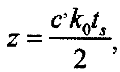
data acquisition card 15, and k 0 is an index value corresponding to the vibration point; the vibration point has a vibration waveform which is a new sequence {Δφ k0 (n);n = 1,···,NL composed of differential phases at k=k 0 on the NL differential phase curves obtained inStep 6. - The spatial resolution Δz of the present embodiment is determined by the sweeping range of the swept-frequency optical probe pulse, i.e.,

- The vibration frequency response bandwidth of the present embodiment is determined by the transmission time interval of the swept-frequency optical probe pulses, i.e., 1/2T. Compared with the traditional solutions, theoretically, the vibration frequency response bandwidth is increased by N times.
- In the present embodiment, a vibration point was set. A single-frequency vibration with a frequency of 21 kHz occurred at 9.93 km of the
sensing fiber 12, and the vibration coverage of the vibration point was 10 m. - In the present embodiment, K=100000, N=5, L=16, NL=80, M=1, and D=100. The bands of the three digital band-pass filters had the bandwidths of 50 to 150 MHz, 150 to 250 MHz, and 250 to 350 MHz, respectively. Then the original data segments of the 80 swept-frequency optical probe pulses were labeled in time order as {xn (k); k=1,···, K}; n=1,···, 80. The divided 80x3=240 sub-data segments were labeled as {xn,m (k); k = 1,···, K}; n=1,···,80; m=1,2,3.
- In the present embodiment, the obtained Rayleigh backscattering signals were


- In the phase variance curves, the variance at k 0 = 99300 was greater than 0.02, so it was determined that this point was the vibration point, and the position of the vibration point on the
sensing fibre 12 was
Figure 3 , the signal-to-noise ratio of the obtained vibration waveform reaches 25dB. - The present embodiment breaks through the limitations of the length of the
sensing fiber 12 on the vibration frequency response range. Since thesensor fibre 12 has a total length of 10 km, the maximum measurable vibration frequency is only 5 kHz in the traditional distributed fibre sensing system based on the optical time-domain reflectometer. However, the vibration frequency of 21 kHz is successfully measured and the signal-to-noise ratio is high in the present embodiment.
Claims (9)
- A distributed fibre sensing system comprising a signal generating module, a light source module, an optical frequency comb generating module, a frequency sweeping and pulse generating module, an optical circulator (11), a sensing fibre (12), an interference module, a photoelectric conversion module (14) and a detection and position module which includes a data acquisition card (15) and a positioning unit (16) which are connected to each other, wherein:the signal generating module inputs an amplified swept radio frequency pulse sequence and an amplified single-frequency sinusoidal wave signal to the frequency sweeping and pulse generating module and the optical frequency comb generating module respectively, and the signal generating module sends a trigger signal to the detection and position module at the same time;an ultra-narrow-linewidth laser generated by the light source module is split into a detection light path and a reference light path which are then output to the optical frequency comb generating module and the interference module, respectively;the optical frequency comb generating module inputs an optical frequency comb signal to the frequency sweeping and pulse generating module, and the frequency sweeping and pulse generating module outputs an amplified swept-frequency optical probe pulse string which is then input into the sensing fibre (12) through the optical circulator (11);a Rayleigh backscattering light generated by the sensing fibre (12) is input to the interference module through the optical circulator (11) and mixed with a reference light at the interference module to generate a mixed optical signal, and the mixed optical signal is input into the photoelectric conversion module (14);wherein the photoelectric conversion module (14) is configured to convert the mixed optical signal into an electric signal, and input the electric signal to the data acquisition card (15),wherein the data acquisition card (15) is configured to sample the input electric signal, and input original data into the positioning unit (16) for phase demodulation, characterized in thatthe positioning unit (16) is configured to(a) generate a plurality of digital band-pass filters with different frequency bands without any overlapping, and performing digital filtering on original data segments from a plurality of swept-frequency optical probe pulses, thereby obtaining a plurality of Rayleigh backscattering signals of the sensing fibre (12);(b) perform a fading elimination processing on the Rayleigh backscattering signals, thereby obtaining a plurality of averaged Rayleigh backscattering signals without interference fading and polarization fading;(c) obtain phase curves based on phase terms of each averaged Rayleigh backscattering signal;(d) delay the phase curves by applying a time shift;(e) determine the difference between the phase curves before and after the time shift to obtain differential phase curves; and finding the variance of the differential phase curves, thereby obtaining a phase variance curve;(f) determine a vibration point according to variances in the phase variance curve, and finally obtaining a position and a vibration waveform of the vibration point.
- The distributed fibre sensing system according to claim 1, wherein:the signal generating module comprises: an arbitrary signal generator (1) and two radio frequency signal amplifiers (2; 3), the two radio frequency signal amplifiers (2; 3) are connected to two output channels of the arbitrary signal generator (1) respectively;one channel of the arbitrary signal generator (1) repeatedly outputs a swept radio frequency pulse sequence, and the other channel outputs a single-frequency sinusoidal wave signal, the swept radio frequency pulse sequence comprises: a plurality of swept radio frequency pulse signals with equal time interval, same pulse width, and different and non-overlapped sweeping ranges.
- The distributed fibre sensing system according to claim 2, wherein
the product of the time interval and the number of swept radio frequency pulse signals is equal to the round trip time of light in the sensing fibre (12). - The distributed fibre sensing system according to claim 1, wherein:the light source module comprises a narrow-linewidth fibre laser device (4), a fibre coupler (5) and a polarization controller (6) which are connected in sequence;the fibre coupler has a split ratio of 90:10.
- The distributed fibre sensing system according to claim 1, wherein:the optical frequency comb generating module comprises a DC voltage source (7) and an optical modulator (8);the DC voltage source (7) adjusts a DC bias voltage input into the optical modulator (8) and generates the optical frequency comb signal.
- The distributed fibre sensing system according to claim 1, wherein
the frequency sweeping and pulse generating module comprises an acousto-optic modulator (9)/single-sideband modulator and an erbium-doped fibre amplifier (10) which are connected to each other. - The distributed fibre sensing system according to claim 1, wherein
the Rayleigh backscattering signals are obtained by the following method:generating a plurality of digital band-pass filters with different frequency bands without any overlapping by the positioning unit (16);dividing the original data segments from the plurality of swept-frequency optical probe pulses into sub-data segments, the number of which is equal to that of the digital band-pass filters;and then performing a cross-correlation operation on the sub-data segments and the corresponding digital matched filters, thereby obtaining a set of Rayleigh backscattering signals of the sensing fibre. - The distributed fibre sensing system according to claim 1, wherein
the fading elimination processing includes: taking the conjugate of one Rayleigh backscattering signal as a reference value, multiplying the other Rayleigh backscattering signals with the reference value, thereby obtaining a set of Rayleigh backscattering signals of return-to-zero phase; and averaging the Rayleigh backscattering signals of return-to-zero phase, thereby obtaining averaged Rayleigh backscattering signals without interference fading and polarization fading. - The distributed fibre sensing system according to claim 1, wherein:the determination of the vibration point includes setting a point on the phase variance curve as the vibration point, the set point having a variance on the phase variance curve greater than 0.02;the position of the vibration point on the sensing fibre is
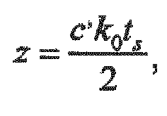 the vibration point has a vibration waveform which is a new sequence composed of differential phases at the vibration point in the differential phase curve.
Applications Claiming Priority (2)
| Application Number | Priority Date | Filing Date | Title |
|---|---|---|---|
| CN201610719172.3A CN106092305B (en) | 2016-08-25 | 2016-08-25 | Distributed optical fiber sensing system and vibration detection positioning method thereof |
| PCT/CN2016/096807 WO2018035833A1 (en) | 2016-08-25 | 2016-08-26 | Distributed fibre sensing system and vibration detection and positioning method therefor |
Publications (3)
| Publication Number | Publication Date |
|---|---|
| EP3483572A1 EP3483572A1 (en) | 2019-05-15 |
| EP3483572A4 EP3483572A4 (en) | 2020-03-18 |
| EP3483572B1 true EP3483572B1 (en) | 2021-06-23 |
Family
ID=57224977
Family Applications (1)
| Application Number | Title | Priority Date | Filing Date |
|---|---|---|---|
| EP16913855.9A Active EP3483572B1 (en) | 2016-08-25 | 2016-08-26 | Distributed fibre sensing system and vibration detection and positioning method therefor |
Country Status (5)
| Country | Link |
|---|---|
| US (1) | US10989587B2 (en) |
| EP (1) | EP3483572B1 (en) |
| JP (1) | JP6695001B2 (en) |
| CN (1) | CN106092305B (en) |
| WO (1) | WO2018035833A1 (en) |
Families Citing this family (58)
| Publication number | Priority date | Publication date | Assignee | Title |
|---|---|---|---|---|
| CN107990970B (en) * | 2017-11-03 | 2019-10-15 | 上海交通大学 | Method for Eliminating Fading Noise in Distributed Optical Fiber Acoustic System |
| CN108415067B (en) * | 2017-12-28 | 2020-02-14 | 华中科技大学 | Earthquake wave measuring system based on microstructure optical fiber distributed acoustic wave sensing |
| US10816368B2 (en) * | 2018-01-24 | 2020-10-27 | Prisma Photonics Ltd. | Method and system for high sensitivity in distributed fiber sensing applications |
| CN110118594B (en) * | 2019-04-22 | 2020-07-10 | 华中科技大学 | A kind of optical phase demodulation method and system based on polarization polarization receiving |
| US10979140B2 (en) * | 2019-07-09 | 2021-04-13 | Huawei Technologies Co., Ltd. | Method and apparatus for detecting operational conditions of an optical link in an optical network |
| CN110285333B (en) * | 2019-07-12 | 2024-12-17 | 上海交通大学 | Oil gas pipeline leakage monitoring method of oil gas pipeline leakage monitoring system based on optical fiber |
| CN110346167B (en) * | 2019-08-20 | 2025-03-14 | 电子科技大学 | A bridge safety monitoring method and monitoring mechanism based on optical fiber |
| CN110749899A (en) * | 2019-10-11 | 2020-02-04 | 中国石化销售股份有限公司华中分公司 | A long-distance pipeline pig tracking and positioning device |
| CN111181631B (en) * | 2019-12-25 | 2024-09-13 | 中国电子科技集团公司第三十四研究所 | Submarine optical cable disturbance monitoring system with relay based on time division space division multiplexing |
| CN111157102B (en) * | 2020-01-02 | 2022-03-08 | 河海大学常州校区 | Positioning method for eliminating frequency interference in distributed optical fiber sensing system |
| JP7435160B2 (en) * | 2020-03-30 | 2024-02-21 | 沖電気工業株式会社 | Optical fiber vibration detection device and vibration detection method |
| CN111609919B (en) * | 2020-06-09 | 2021-06-01 | 重庆大学 | Optical Fiber Distributed Vibration and Loss Simultaneous Detection System |
| CL2020001869A1 (en) * | 2020-07-14 | 2020-09-11 | Mario Francisco Rendic Munoz | Continuous condition monitoring (mcc) system for conveyor belts based on a fiber optic distributed sensor |
| CN112129243B (en) * | 2020-09-04 | 2022-02-15 | 电子科技大学 | Quasi-distributed optical fiber torsion angle measuring device and method based on photoelectric oscillator |
| CN112067113B (en) * | 2020-09-08 | 2022-03-25 | 武汉理工光科股份有限公司 | Method and device for determining propagation velocity of Rayleigh waves in soil |
| CN112097813B (en) * | 2020-09-14 | 2022-05-17 | 中国人民解放军国防科技大学 | A 3×3 coupler photoelectric detection method and device based on optical frequency modulation |
| CN112082498A (en) * | 2020-09-14 | 2020-12-15 | 安徽大学 | Noise suppression sensing method for OFDR strain and temperature based on phase measurement method |
| CN114459710B (en) * | 2020-10-22 | 2025-04-01 | 中国石油化工股份有限公司 | Storage device, submarine cable fault detection and diagnosis method, device, equipment and system |
| CN112504629B (en) * | 2020-11-24 | 2021-08-24 | 北京大学 | Light scattering parameter measuring system and measuring method thereof |
| CN112697181B (en) * | 2020-12-02 | 2022-07-26 | 广东工业大学 | A frequency modulation-based phase-sensitive optical time-domain reflectometry device and method |
| CN112444218B (en) * | 2020-12-09 | 2025-03-07 | 桂林聚联科技有限公司 | Device and method for measuring optical cable laying depth |
| US11733089B2 (en) * | 2020-12-22 | 2023-08-22 | Nec Corporation | Context encoder-based fiber sensing anomaly detection |
| CN112611444B (en) * | 2020-12-30 | 2023-04-28 | 西安和其光电科技股份有限公司 | Distributed optical fiber vibration monitoring system and method capable of achieving accurate positioning |
| CN112747815B (en) * | 2021-01-06 | 2024-02-02 | 苏州光格科技股份有限公司 | A coherent fading noise suppression method in distributed optical fiber acoustic wave sensing system |
| KR102392287B1 (en) * | 2021-05-04 | 2022-05-02 | 에피텍(주) | System for estimating location of using vibration source underground optical cable and application method thereof |
| CN113432702B (en) * | 2021-05-25 | 2023-01-31 | 天津大学 | A system and method for detecting acoustic signals across the cavitation layer in the ocean based on optical heterodyne |
| CN113639848B (en) * | 2021-08-10 | 2022-10-21 | 福州大学 | High-performance frequency-sweeping optical coherent vibration meter with multipoint synchronous vibration measurement and method |
| CN113483880A (en) * | 2021-08-17 | 2021-10-08 | 广东电网有限责任公司 | Vibration sensing system based on few-mode optical fiber |
| CN113984182B (en) * | 2021-11-04 | 2024-07-09 | 国家石油天然气管网集团有限公司 | A distributed lateral vibration source distance positioning method for oil and gas pipelines |
| CN114235135B (en) * | 2021-12-22 | 2023-05-26 | 桂林电子科技大学 | Amplitude demodulation vibration positioning detection method based on double differential step sizes |
| CN116350174A (en) * | 2021-12-27 | 2023-06-30 | 华为技术有限公司 | A brain-computer interface device and information acquisition method |
| CN116772908A (en) * | 2021-12-28 | 2023-09-19 | 西安和其光电科技股份有限公司 | Signal data processing method applied to distributed optical fiber acoustic wave sensing system |
| CN114482988B (en) * | 2021-12-28 | 2024-05-31 | 中煤科工集团西安研究院有限公司 | Water-bearing layer water outlet section positioning system and method adopting distributed acoustic sensing equipment |
| CN116429236B (en) * | 2021-12-30 | 2025-10-17 | 中国石油天然气集团有限公司 | Method and device for suppressing coherent fading noise of optical fiber sensing data |
| CN114485900B (en) * | 2021-12-31 | 2023-10-03 | 武汉光谷互连科技有限公司 | Fading-free demodulation method for direct detection of distributed acoustic wave sensing systems |
| CN114383713A (en) * | 2022-02-26 | 2022-04-22 | 中企科信技术股份有限公司 | Distributed optical fiber vibration sensing system, acoustic emission monitoring system and manufacturing method |
| CN114692408B (en) * | 2022-03-28 | 2024-12-13 | 中国石油大学(华东) | A simulation modeling method for distributed fiber optic acoustic sensing system |
| CN114838240A (en) * | 2022-04-26 | 2022-08-02 | 天津市誉航润铭科技发展有限公司 | An operation monitoring system of a detector in a pipeline and a detection and positioning method |
| CN115014406B (en) * | 2022-05-11 | 2025-07-29 | 哈尔滨理工大学 | Phase sensitive optical time domain reflectometer based on broadband AOM (optical fiber) to inhibit coherent fading effect and working method thereof |
| CN115046621B (en) * | 2022-05-16 | 2025-10-31 | 之江实验室 | Broadband quasi-distributed optical fiber acoustic wave sensing method and system based on sine sweep frequency |
| CN115165067A (en) * | 2022-05-16 | 2022-10-11 | 之江实验室 | Broadband distributed acoustic wave sensing method and system based on optical channelization |
| CN114993448B (en) * | 2022-06-09 | 2023-04-07 | 西北大学 | Long-distance distributed vibration monitoring device and monitoring method |
| CN115452124B (en) * | 2022-09-13 | 2025-10-28 | 武汉理工光科股份有限公司 | Method, system and device for analyzing motion state of excitation source based on distributed optical fiber |
| CN115824378B (en) * | 2022-10-09 | 2025-10-17 | 上海交通大学 | Vibration detection method of high-frequency response distributed optical fiber acoustic wave sensor |
| CN115752696A (en) * | 2022-10-21 | 2023-03-07 | 深圳大学 | Distributed optical fiber vibration sensing system based on forward transmission and signal processing method |
| CN116155373B (en) * | 2022-11-14 | 2024-06-18 | 中铁第四勘察设计院集团有限公司 | Single-fiber bidirectional fusion positioning type railway optical cable monitoring system and method |
| CN115901043B (en) * | 2022-11-17 | 2025-03-18 | 重庆大学 | Power cable external force monitoring system and method based on distributed optical fiber sensing |
| CN116481449B (en) * | 2023-04-26 | 2025-10-17 | 国家能源集团宁夏煤业有限责任公司 | Surrounding rock deformation determination method and device and surrounding rock deformation detection system |
| CN116186642B (en) * | 2023-04-27 | 2023-09-08 | 山东汇英光电科技有限公司 | Distributed optical fiber sensing event early warning method based on multidimensional feature fusion |
| CN116756640A (en) * | 2023-05-26 | 2023-09-15 | 广东电网有限责任公司广州供电局 | Method and system for eliminating vibration effects of optical current transformer based on waveform recognition |
| CN116818082B (en) * | 2023-06-01 | 2025-12-09 | 中国地质大学(武汉) | Method and device for suppressing interference fading and storage device |
| CN117350226B (en) * | 2023-09-26 | 2024-12-13 | 固势(苏州)科技有限公司 | A method for collecting state parameters of IGBT devices |
| CN117708506B (en) * | 2024-02-05 | 2024-04-26 | 山东省科学院激光研究所 | Method and system for eliminating deterioration effect caused by distributed acoustic wave sensing coherent fading |
| CN118013401B (en) * | 2024-04-10 | 2024-07-26 | 宁波联河光子技术有限公司 | DAS-based belt conveyor vibration false alarm suppression method |
| CN119727917A (en) * | 2024-06-17 | 2025-03-28 | 武汉光迅科技股份有限公司 | A distributed optical fiber synaesthesia integrated system and implementation method |
| CN119568431B (en) * | 2024-11-26 | 2025-11-18 | 南京航空航天大学 | A device for measuring steady-state vibration in aircraft hydraulic lines and a method for locating abnormal vibration points. |
| CN119826698B (en) * | 2025-02-05 | 2025-10-10 | 武汉理工大学 | A method and system for locating overall and local bolt loosening in pipeline flange connections |
| CN121005201B (en) * | 2025-10-28 | 2026-01-27 | 太原理工大学 | LFM-DAS-based roller abnormality diagnosis system |
Family Cites Families (19)
| Publication number | Priority date | Publication date | Assignee | Title |
|---|---|---|---|---|
| GB2136113B (en) * | 1983-03-05 | 1986-08-06 | Plessey Co Plc | Improvements relating to optical sensing systems |
| JPS61105438A (en) * | 1984-10-29 | 1986-05-23 | Nippon Denso Co Ltd | Oscillation testing device |
| DE69019289T2 (en) * | 1989-10-27 | 1996-02-01 | Storz Instr Co | Method for driving an ultrasonic transducer. |
| EP1825215B1 (en) * | 2004-12-14 | 2013-10-30 | Luna Innovations, Inc. | Compensating for time varying phase changes in interferometric measurements |
| CA2640462C (en) * | 2008-10-03 | 2016-06-28 | Zetec, Inc. | System and method for ultrasonic testing |
| CA2809660C (en) * | 2010-09-01 | 2016-11-15 | Schlumberger Canada Limited | Distributed fiber optic sensor system with improved linearity |
| CN102322880B (en) | 2011-08-18 | 2013-06-05 | 天津大学 | Polarization sensitive distributive optical frequency domain reflection disturbance sensor and demodulation method |
| CN102628698B (en) | 2012-04-06 | 2015-02-18 | 中国科学院上海光学精密机械研究所 | Distributed optical fiber sensor and information demodulating method |
| CN103759750B (en) * | 2014-01-23 | 2016-05-25 | 中国科学院半导体研究所 | Based on the distributed optical fiber sensing system of phase generated carrier technology |
| WO2016021689A1 (en) * | 2014-08-07 | 2016-02-11 | 古河電気工業株式会社 | Optical fiber sensor, seismic prospecting method, method for measuring distribution of petroleum/natural gas reservoir layer, strain detection method, and method for specifying position of fissure in stratum |
| JP6240585B2 (en) * | 2014-10-27 | 2017-11-29 | 日本電信電話株式会社 | Optical fiber vibration sensor and vibration measuring method |
| US9500562B2 (en) * | 2015-02-05 | 2016-11-22 | University Of Ottawa | Kerr phase-interrogator for sensing and signal processing applications |
| CN104700624B (en) * | 2015-03-16 | 2017-07-07 | 电子科技大学 | The monitoring method of the vehicle flowrate on-line monitoring system based on phase sensitivity optical time domain reflectometer |
| CN104677396B (en) * | 2015-03-19 | 2017-05-10 | 广西师范大学 | Dynamic distributed Brillouin optical fiber sensing device and method |
| CN104990620B (en) * | 2015-07-03 | 2018-06-08 | 南京大学 | Phase-sensitive optical time domain reflection device and method based on fiber Bragg grating array |
| CN105067103B (en) * | 2015-08-31 | 2018-01-02 | 上海交通大学 | Vibration detection device and method based on optical frequency domain reflectometer |
| CN105466548B (en) * | 2015-12-16 | 2019-06-04 | 上海大学 | Positioning method for phase sensitive optical time domain reflectometry fiber optic sensing system |
| CN105403257A (en) * | 2015-12-24 | 2016-03-16 | 四川师范大学 | Distribution type Brillouin time domain analysis system |
| CN105490738B (en) * | 2016-01-05 | 2017-10-03 | 上海交通大学 | Optical frequency domain reflection method and system based on frequency synthesis |
-
2016
- 2016-08-25 CN CN201610719172.3A patent/CN106092305B/en active Active
- 2016-08-26 JP JP2019506366A patent/JP6695001B2/en active Active
- 2016-08-26 EP EP16913855.9A patent/EP3483572B1/en active Active
- 2016-08-26 US US16/322,259 patent/US10989587B2/en active Active
- 2016-08-26 WO PCT/CN2016/096807 patent/WO2018035833A1/en not_active Ceased
Also Published As
| Publication number | Publication date |
|---|---|
| WO2018035833A1 (en) | 2018-03-01 |
| JP6695001B2 (en) | 2020-05-20 |
| CN106092305A (en) | 2016-11-09 |
| CN106092305B (en) | 2022-02-18 |
| US20200182685A1 (en) | 2020-06-11 |
| EP3483572A4 (en) | 2020-03-18 |
| US10989587B2 (en) | 2021-04-27 |
| EP3483572A1 (en) | 2019-05-15 |
| JP2019525181A (en) | 2019-09-05 |
Similar Documents
| Publication | Publication Date | Title |
|---|---|---|
| US10989587B2 (en) | Distributed fibre sensing system and vibration detection and positioning method therefor | |
| CN106052842B (en) | Distributed optical fiber vibration sensing system capable of eliminating fading noise and its demodulation method | |
| JP6698164B2 (en) | Optical frequency domain reflection method and system based on frequency synthesis | |
| CN107505041B (en) | A phase demodulation device and method based on phase sensitive optical time domain reflectometer | |
| CN105490738A (en) | Optical Frequency Domain Reflectometry Method and System Based on Frequency Synthesis | |
| CN112880711B (en) | Distributed optical fiber sensing method and system based on double pulse modulation | |
| CN107063431A (en) | A kind of optical fiber vibration sensing system and method based on double light path | |
| CN102645268A (en) | Optical frequency division multiplexing phase-sensitive optical time domain reflectometer | |
| CN104180833A (en) | Optical time domain reflectometer simultaneously sensing temperature and stress | |
| CN104568119A (en) | Optical fiber vibration sensing system of single light source pulse and sensing method thereof | |
| CN107340050B (en) | Optical fiber distributed vibration sensing system and phase discrimination nonlinear error correction method | |
| CN110470327A (en) | A kind of optical time-domain analyzer and analysis method | |
| CN103900623A (en) | Optical time domain reflectometer based on double acoustic-optical modulators and common-mode rejection method of optical time domain reflectometer | |
| CN205981438U (en) | Distributed optical fiber sensing system | |
| CN116295782B (en) | A distributed optical fiber vibration sensing system and phase demodulation method based on Φ-OTDR | |
| CN205453695U (en) | Optical Frequency Domain Reflectometry Based on Frequency Synthesis | |
| CN115876350A (en) | A Fast Brillouin Optical Correlation Domain Analyzer Based on Optical Frequency Comb | |
| US20190226885A1 (en) | Method and system for high sensitivity in distributed fiber sensing applications | |
| CN109724529B (en) | Large dynamic range Brillouin fast measurement system based on multi-slope assistance | |
| CN205898286U (en) | Distributed Fiber Optic Vibration Sensing System Can Eliminate Fading Noise | |
| CN108540219B (en) | coherent optical receiver parameter measurement method and device based on frequency shift modulation | |
| CN116067479B (en) | Distributed fiber optic sensing system for joint dynamic and static measurement of temperature and strain separable | |
| CN107687939B (en) | Optical fiber detection device and method for interference type optical fiber hydrophone sensing arm | |
| CN102841355A (en) | Device and method for measuring data of femtosecond range laser radar based on microwave photonics | |
| CN117490741A (en) | Quick Brillouin optical time domain analyzer based on double-sideband optical frequency comb |
Legal Events
| Date | Code | Title | Description |
|---|---|---|---|
| STAA | Information on the status of an ep patent application or granted ep patent |
Free format text: STATUS: THE INTERNATIONAL PUBLICATION HAS BEEN MADE |
|
| PUAI | Public reference made under article 153(3) epc to a published international application that has entered the european phase |
Free format text: ORIGINAL CODE: 0009012 |
|
| STAA | Information on the status of an ep patent application or granted ep patent |
Free format text: STATUS: REQUEST FOR EXAMINATION WAS MADE |
|
| 17P | Request for examination filed |
Effective date: 20190207 |
|
| AK | Designated contracting states |
Kind code of ref document: A1 Designated state(s): AL AT BE BG CH CY CZ DE DK EE ES FI FR GB GR HR HU IE IS IT LI LT LU LV MC MK MT NL NO PL PT RO RS SE SI SK SM TR |
|
| AX | Request for extension of the european patent |
Extension state: BA ME |
|
| RAP1 | Party data changed (applicant data changed or rights of an application transferred) |
Owner name: SHANGHAI JIAOTONG UNIVERSITY Owner name: NEUBREX CO., LTD. |
|
| RIN1 | Information on inventor provided before grant (corrected) |
Inventor name: HE, ZUYUAN Inventor name: FAN, XINYU Inventor name: LIU, QINGWEN Inventor name: CHEN, DIAN |
|
| DAV | Request for validation of the european patent (deleted) | ||
| DAX | Request for extension of the european patent (deleted) | ||
| A4 | Supplementary search report drawn up and despatched |
Effective date: 20200219 |
|
| RIC1 | Information provided on ipc code assigned before grant |
Ipc: G01H 9/00 20060101AFI20200213BHEP Ipc: G01D 5/353 20060101ALI20200213BHEP |
|
| GRAP | Despatch of communication of intention to grant a patent |
Free format text: ORIGINAL CODE: EPIDOSNIGR1 |
|
| STAA | Information on the status of an ep patent application or granted ep patent |
Free format text: STATUS: GRANT OF PATENT IS INTENDED |
|
| INTG | Intention to grant announced |
Effective date: 20210128 |
|
| RIN1 | Information on inventor provided before grant (corrected) |
Inventor name: LIU, QINGWEN Inventor name: FAN, XINYU Inventor name: HE, ZUYUAN Inventor name: CHEN, DIAN |
|
| GRAS | Grant fee paid |
Free format text: ORIGINAL CODE: EPIDOSNIGR3 |
|
| GRAA | (expected) grant |
Free format text: ORIGINAL CODE: 0009210 |
|
| STAA | Information on the status of an ep patent application or granted ep patent |
Free format text: STATUS: THE PATENT HAS BEEN GRANTED |
|
| AK | Designated contracting states |
Kind code of ref document: B1 Designated state(s): AL AT BE BG CH CY CZ DE DK EE ES FI FR GB GR HR HU IE IS IT LI LT LU LV MC MK MT NL NO PL PT RO RS SE SI SK SM TR |
|
| REG | Reference to a national code |
Ref country code: GB Ref legal event code: FG4D |
|
| REG | Reference to a national code |
Ref country code: CH Ref legal event code: EP |
|
| REG | Reference to a national code |
Ref country code: DE Ref legal event code: R096 Ref document number: 602016059829 Country of ref document: DE Ref country code: AT Ref legal event code: REF Ref document number: 1404687 Country of ref document: AT Kind code of ref document: T Effective date: 20210715 |
|
| REG | Reference to a national code |
Ref country code: IE Ref legal event code: FG4D |
|
| REG | Reference to a national code |
Ref country code: LT Ref legal event code: MG9D |
|
| PG25 | Lapsed in a contracting state [announced via postgrant information from national office to epo] |
Ref country code: LT Free format text: LAPSE BECAUSE OF FAILURE TO SUBMIT A TRANSLATION OF THE DESCRIPTION OR TO PAY THE FEE WITHIN THE PRESCRIBED TIME-LIMIT Effective date: 20210623 Ref country code: FI Free format text: LAPSE BECAUSE OF FAILURE TO SUBMIT A TRANSLATION OF THE DESCRIPTION OR TO PAY THE FEE WITHIN THE PRESCRIBED TIME-LIMIT Effective date: 20210623 Ref country code: BG Free format text: LAPSE BECAUSE OF FAILURE TO SUBMIT A TRANSLATION OF THE DESCRIPTION OR TO PAY THE FEE WITHIN THE PRESCRIBED TIME-LIMIT Effective date: 20210923 Ref country code: HR Free format text: LAPSE BECAUSE OF FAILURE TO SUBMIT A TRANSLATION OF THE DESCRIPTION OR TO PAY THE FEE WITHIN THE PRESCRIBED TIME-LIMIT Effective date: 20210623 |
|
| REG | Reference to a national code |
Ref country code: AT Ref legal event code: MK05 Ref document number: 1404687 Country of ref document: AT Kind code of ref document: T Effective date: 20210623 |
|
| PG25 | Lapsed in a contracting state [announced via postgrant information from national office to epo] |
Ref country code: NO Free format text: LAPSE BECAUSE OF FAILURE TO SUBMIT A TRANSLATION OF THE DESCRIPTION OR TO PAY THE FEE WITHIN THE PRESCRIBED TIME-LIMIT Effective date: 20210923 Ref country code: SE Free format text: LAPSE BECAUSE OF FAILURE TO SUBMIT A TRANSLATION OF THE DESCRIPTION OR TO PAY THE FEE WITHIN THE PRESCRIBED TIME-LIMIT Effective date: 20210623 Ref country code: RS Free format text: LAPSE BECAUSE OF FAILURE TO SUBMIT A TRANSLATION OF THE DESCRIPTION OR TO PAY THE FEE WITHIN THE PRESCRIBED TIME-LIMIT Effective date: 20210623 Ref country code: LV Free format text: LAPSE BECAUSE OF FAILURE TO SUBMIT A TRANSLATION OF THE DESCRIPTION OR TO PAY THE FEE WITHIN THE PRESCRIBED TIME-LIMIT Effective date: 20210623 Ref country code: GR Free format text: LAPSE BECAUSE OF FAILURE TO SUBMIT A TRANSLATION OF THE DESCRIPTION OR TO PAY THE FEE WITHIN THE PRESCRIBED TIME-LIMIT Effective date: 20210924 |
|
| REG | Reference to a national code |
Ref country code: NL Ref legal event code: MP Effective date: 20210623 |
|
| PG25 | Lapsed in a contracting state [announced via postgrant information from national office to epo] |
Ref country code: RO Free format text: LAPSE BECAUSE OF FAILURE TO SUBMIT A TRANSLATION OF THE DESCRIPTION OR TO PAY THE FEE WITHIN THE PRESCRIBED TIME-LIMIT Effective date: 20210623 Ref country code: PT Free format text: LAPSE BECAUSE OF FAILURE TO SUBMIT A TRANSLATION OF THE DESCRIPTION OR TO PAY THE FEE WITHIN THE PRESCRIBED TIME-LIMIT Effective date: 20211025 Ref country code: NL Free format text: LAPSE BECAUSE OF FAILURE TO SUBMIT A TRANSLATION OF THE DESCRIPTION OR TO PAY THE FEE WITHIN THE PRESCRIBED TIME-LIMIT Effective date: 20210623 Ref country code: ES Free format text: LAPSE BECAUSE OF FAILURE TO SUBMIT A TRANSLATION OF THE DESCRIPTION OR TO PAY THE FEE WITHIN THE PRESCRIBED TIME-LIMIT Effective date: 20210623 Ref country code: EE Free format text: LAPSE BECAUSE OF FAILURE TO SUBMIT A TRANSLATION OF THE DESCRIPTION OR TO PAY THE FEE WITHIN THE PRESCRIBED TIME-LIMIT Effective date: 20210623 Ref country code: CZ Free format text: LAPSE BECAUSE OF FAILURE TO SUBMIT A TRANSLATION OF THE DESCRIPTION OR TO PAY THE FEE WITHIN THE PRESCRIBED TIME-LIMIT Effective date: 20210623 Ref country code: AT Free format text: LAPSE BECAUSE OF FAILURE TO SUBMIT A TRANSLATION OF THE DESCRIPTION OR TO PAY THE FEE WITHIN THE PRESCRIBED TIME-LIMIT Effective date: 20210623 Ref country code: SK Free format text: LAPSE BECAUSE OF FAILURE TO SUBMIT A TRANSLATION OF THE DESCRIPTION OR TO PAY THE FEE WITHIN THE PRESCRIBED TIME-LIMIT Effective date: 20210623 Ref country code: SM Free format text: LAPSE BECAUSE OF FAILURE TO SUBMIT A TRANSLATION OF THE DESCRIPTION OR TO PAY THE FEE WITHIN THE PRESCRIBED TIME-LIMIT Effective date: 20210623 |
|
| PG25 | Lapsed in a contracting state [announced via postgrant information from national office to epo] |
Ref country code: PL Free format text: LAPSE BECAUSE OF FAILURE TO SUBMIT A TRANSLATION OF THE DESCRIPTION OR TO PAY THE FEE WITHIN THE PRESCRIBED TIME-LIMIT Effective date: 20210623 |
|
| REG | Reference to a national code |
Ref country code: DE Ref legal event code: R097 Ref document number: 602016059829 Country of ref document: DE |
|
| REG | Reference to a national code |
Ref country code: CH Ref legal event code: PL |
|
| PG25 | Lapsed in a contracting state [announced via postgrant information from national office to epo] |
Ref country code: MC Free format text: LAPSE BECAUSE OF FAILURE TO SUBMIT A TRANSLATION OF THE DESCRIPTION OR TO PAY THE FEE WITHIN THE PRESCRIBED TIME-LIMIT Effective date: 20210623 |
|
| REG | Reference to a national code |
Ref country code: BE Ref legal event code: MM Effective date: 20210831 |
|
| PG25 | Lapsed in a contracting state [announced via postgrant information from national office to epo] |
Ref country code: LI Free format text: LAPSE BECAUSE OF NON-PAYMENT OF DUE FEES Effective date: 20210831 Ref country code: DK Free format text: LAPSE BECAUSE OF FAILURE TO SUBMIT A TRANSLATION OF THE DESCRIPTION OR TO PAY THE FEE WITHIN THE PRESCRIBED TIME-LIMIT Effective date: 20210623 Ref country code: CH Free format text: LAPSE BECAUSE OF NON-PAYMENT OF DUE FEES Effective date: 20210831 |
|
| PLBE | No opposition filed within time limit |
Free format text: ORIGINAL CODE: 0009261 |
|
| STAA | Information on the status of an ep patent application or granted ep patent |
Free format text: STATUS: NO OPPOSITION FILED WITHIN TIME LIMIT |
|
| 26N | No opposition filed |
Effective date: 20220324 |
|
| PG25 | Lapsed in a contracting state [announced via postgrant information from national office to epo] |
Ref country code: AL Free format text: LAPSE BECAUSE OF FAILURE TO SUBMIT A TRANSLATION OF THE DESCRIPTION OR TO PAY THE FEE WITHIN THE PRESCRIBED TIME-LIMIT Effective date: 20210623 Ref country code: LU Free format text: LAPSE BECAUSE OF NON-PAYMENT OF DUE FEES Effective date: 20210826 |
|
| PG25 | Lapsed in a contracting state [announced via postgrant information from national office to epo] |
Ref country code: IT Free format text: LAPSE BECAUSE OF FAILURE TO SUBMIT A TRANSLATION OF THE DESCRIPTION OR TO PAY THE FEE WITHIN THE PRESCRIBED TIME-LIMIT Effective date: 20210623 Ref country code: IE Free format text: LAPSE BECAUSE OF NON-PAYMENT OF DUE FEES Effective date: 20210826 Ref country code: BE Free format text: LAPSE BECAUSE OF NON-PAYMENT OF DUE FEES Effective date: 20210831 |
|
| PG25 | Lapsed in a contracting state [announced via postgrant information from national office to epo] |
Ref country code: CY Free format text: LAPSE BECAUSE OF FAILURE TO SUBMIT A TRANSLATION OF THE DESCRIPTION OR TO PAY THE FEE WITHIN THE PRESCRIBED TIME-LIMIT Effective date: 20210623 |
|
| PG25 | Lapsed in a contracting state [announced via postgrant information from national office to epo] |
Ref country code: HU Free format text: LAPSE BECAUSE OF FAILURE TO SUBMIT A TRANSLATION OF THE DESCRIPTION OR TO PAY THE FEE WITHIN THE PRESCRIBED TIME-LIMIT; INVALID AB INITIO Effective date: 20160826 |
|
| PG25 | Lapsed in a contracting state [announced via postgrant information from national office to epo] |
Ref country code: MK Free format text: LAPSE BECAUSE OF FAILURE TO SUBMIT A TRANSLATION OF THE DESCRIPTION OR TO PAY THE FEE WITHIN THE PRESCRIBED TIME-LIMIT Effective date: 20210623 |
|
| PG25 | Lapsed in a contracting state [announced via postgrant information from national office to epo] |
Ref country code: MT Free format text: LAPSE BECAUSE OF FAILURE TO SUBMIT A TRANSLATION OF THE DESCRIPTION OR TO PAY THE FEE WITHIN THE PRESCRIBED TIME-LIMIT Effective date: 20210623 |
|
| PGFP | Annual fee paid to national office [announced via postgrant information from national office to epo] |
Ref country code: DE Payment date: 20250827 Year of fee payment: 10 |
|
| PGFP | Annual fee paid to national office [announced via postgrant information from national office to epo] |
Ref country code: GB Payment date: 20250827 Year of fee payment: 10 |
|
| PGFP | Annual fee paid to national office [announced via postgrant information from national office to epo] |
Ref country code: FR Payment date: 20250827 Year of fee payment: 10 |
|
| PG25 | Lapsed in a contracting state [announced via postgrant information from national office to epo] |
Ref country code: TR Free format text: LAPSE BECAUSE OF FAILURE TO SUBMIT A TRANSLATION OF THE DESCRIPTION OR TO PAY THE FEE WITHIN THE PRESCRIBED TIME-LIMIT Effective date: 20210623 |