EP3483497A1 - Gehäuse für beleuchtungsvorrichtungen, entsprechende beleuchtungsvorrichtung, beleuchtungsanlage und verfahren - Google Patents
Gehäuse für beleuchtungsvorrichtungen, entsprechende beleuchtungsvorrichtung, beleuchtungsanlage und verfahren Download PDFInfo
- Publication number
- EP3483497A1 EP3483497A1 EP18204518.7A EP18204518A EP3483497A1 EP 3483497 A1 EP3483497 A1 EP 3483497A1 EP 18204518 A EP18204518 A EP 18204518A EP 3483497 A1 EP3483497 A1 EP 3483497A1
- Authority
- EP
- European Patent Office
- Prior art keywords
- channel
- support members
- array
- shaped body
- casing
- Prior art date
- Legal status (The legal status is an assumption and is not a legal conclusion. Google has not performed a legal analysis and makes no representation as to the accuracy of the status listed.)
- Granted
Links
- 238000000034 method Methods 0.000 title claims description 16
- 238000009434 installation Methods 0.000 title claims description 12
- 230000008878 coupling Effects 0.000 claims abstract description 67
- 238000010168 coupling process Methods 0.000 claims abstract description 67
- 238000005859 coupling reaction Methods 0.000 claims abstract description 67
- 230000015572 biosynthetic process Effects 0.000 claims abstract description 49
- 238000005755 formation reaction Methods 0.000 claims abstract description 49
- 230000000295 complement effect Effects 0.000 claims abstract description 9
- 230000005855 radiation Effects 0.000 claims description 22
- 230000003287 optical effect Effects 0.000 claims description 14
- 125000006850 spacer group Chemical group 0.000 claims description 5
- 238000000638 solvent extraction Methods 0.000 claims description 3
- 229910052602 gypsum Inorganic materials 0.000 abstract description 19
- 239000010440 gypsum Substances 0.000 abstract description 19
- 239000000463 material Substances 0.000 description 9
- 239000011505 plaster Substances 0.000 description 6
- 239000002184 metal Substances 0.000 description 3
- 239000002390 adhesive tape Substances 0.000 description 2
- 238000009792 diffusion process Methods 0.000 description 2
- 238000009429 electrical wiring Methods 0.000 description 2
- 238000003780 insertion Methods 0.000 description 2
- 230000037431 insertion Effects 0.000 description 2
- 230000008569 process Effects 0.000 description 2
- 230000009467 reduction Effects 0.000 description 2
- 235000019640 taste Nutrition 0.000 description 2
- 239000002131 composite material Substances 0.000 description 1
- 239000004020 conductor Substances 0.000 description 1
- 238000010276 construction Methods 0.000 description 1
- 230000007547 defect Effects 0.000 description 1
- 239000006185 dispersion Substances 0.000 description 1
- 238000005553 drilling Methods 0.000 description 1
- 230000000694 effects Effects 0.000 description 1
- 238000010292 electrical insulation Methods 0.000 description 1
- 230000004313 glare Effects 0.000 description 1
- 230000017525 heat dissipation Effects 0.000 description 1
- 239000007769 metal material Substances 0.000 description 1
- 230000001681 protective effect Effects 0.000 description 1
- 238000007493 shaping process Methods 0.000 description 1
Images


Classifications
-
- F—MECHANICAL ENGINEERING; LIGHTING; HEATING; WEAPONS; BLASTING
- F21—LIGHTING
- F21S—NON-PORTABLE LIGHTING DEVICES; SYSTEMS THEREOF; VEHICLE LIGHTING DEVICES SPECIALLY ADAPTED FOR VEHICLE EXTERIORS
- F21S8/00—Lighting devices intended for fixed installation
- F21S8/02—Lighting devices intended for fixed installation of recess-mounted type, e.g. downlighters
- F21S8/026—Lighting devices intended for fixed installation of recess-mounted type, e.g. downlighters intended to be recessed in a ceiling or like overhead structure, e.g. suspended ceiling
-
- E—FIXED CONSTRUCTIONS
- E04—BUILDING
- E04B—GENERAL BUILDING CONSTRUCTIONS; WALLS, e.g. PARTITIONS; ROOFS; FLOORS; CEILINGS; INSULATION OR OTHER PROTECTION OF BUILDINGS
- E04B9/00—Ceilings; Construction of ceilings, e.g. false ceilings; Ceiling construction with regard to insulation
- E04B9/006—Ceilings; Construction of ceilings, e.g. false ceilings; Ceiling construction with regard to insulation with means for hanging lighting fixtures or other appliances to the framework of the ceiling
-
- F—MECHANICAL ENGINEERING; LIGHTING; HEATING; WEAPONS; BLASTING
- F21—LIGHTING
- F21S—NON-PORTABLE LIGHTING DEVICES; SYSTEMS THEREOF; VEHICLE LIGHTING DEVICES SPECIALLY ADAPTED FOR VEHICLE EXTERIORS
- F21S4/00—Lighting devices or systems using a string or strip of light sources
- F21S4/20—Lighting devices or systems using a string or strip of light sources with light sources held by or within elongate supports
- F21S4/22—Lighting devices or systems using a string or strip of light sources with light sources held by or within elongate supports flexible or deformable, e.g. into a curved shape
-
- F—MECHANICAL ENGINEERING; LIGHTING; HEATING; WEAPONS; BLASTING
- F21—LIGHTING
- F21V—FUNCTIONAL FEATURES OR DETAILS OF LIGHTING DEVICES OR SYSTEMS THEREOF; STRUCTURAL COMBINATIONS OF LIGHTING DEVICES WITH OTHER ARTICLES, NOT OTHERWISE PROVIDED FOR
- F21V17/00—Fastening of component parts of lighting devices, e.g. shades, globes, refractors, reflectors, filters, screens, grids or protective cages
- F21V17/10—Fastening of component parts of lighting devices, e.g. shades, globes, refractors, reflectors, filters, screens, grids or protective cages characterised by specific fastening means or way of fastening
- F21V17/16—Fastening of component parts of lighting devices, e.g. shades, globes, refractors, reflectors, filters, screens, grids or protective cages characterised by specific fastening means or way of fastening by deformation of parts; Snap action mounting
- F21V17/164—Fastening of component parts of lighting devices, e.g. shades, globes, refractors, reflectors, filters, screens, grids or protective cages characterised by specific fastening means or way of fastening by deformation of parts; Snap action mounting the parts being subjected to bending, e.g. snap joints
-
- F—MECHANICAL ENGINEERING; LIGHTING; HEATING; WEAPONS; BLASTING
- F21—LIGHTING
- F21V—FUNCTIONAL FEATURES OR DETAILS OF LIGHTING DEVICES OR SYSTEMS THEREOF; STRUCTURAL COMBINATIONS OF LIGHTING DEVICES WITH OTHER ARTICLES, NOT OTHERWISE PROVIDED FOR
- F21V21/00—Supporting, suspending, or attaching arrangements for lighting devices; Hand grips
- F21V21/02—Wall, ceiling, or floor bases; Fixing pendants or arms to the bases
- F21V21/04—Recessed bases
- F21V21/048—Mounting arrangements for fastening lighting devices to false ceiling frameworks
-
- E—FIXED CONSTRUCTIONS
- E04—BUILDING
- E04B—GENERAL BUILDING CONSTRUCTIONS; WALLS, e.g. PARTITIONS; ROOFS; FLOORS; CEILINGS; INSULATION OR OTHER PROTECTION OF BUILDINGS
- E04B9/00—Ceilings; Construction of ceilings, e.g. false ceilings; Ceiling construction with regard to insulation
- E04B9/06—Ceilings; Construction of ceilings, e.g. false ceilings; Ceiling construction with regard to insulation characterised by constructional features of the supporting construction, e.g. cross section or material of framework members
- E04B9/065—Ceilings; Construction of ceilings, e.g. false ceilings; Ceiling construction with regard to insulation characterised by constructional features of the supporting construction, e.g. cross section or material of framework members comprising supporting beams having a folded cross-section
-
- E—FIXED CONSTRUCTIONS
- E04—BUILDING
- E04B—GENERAL BUILDING CONSTRUCTIONS; WALLS, e.g. PARTITIONS; ROOFS; FLOORS; CEILINGS; INSULATION OR OTHER PROTECTION OF BUILDINGS
- E04B9/00—Ceilings; Construction of ceilings, e.g. false ceilings; Ceiling construction with regard to insulation
- E04B9/06—Ceilings; Construction of ceilings, e.g. false ceilings; Ceiling construction with regard to insulation characterised by constructional features of the supporting construction, e.g. cross section or material of framework members
- E04B9/12—Connections between non-parallel members of the supporting construction
- E04B9/16—Connections between non-parallel members of the supporting construction the members lying in different planes
-
- F—MECHANICAL ENGINEERING; LIGHTING; HEATING; WEAPONS; BLASTING
- F21—LIGHTING
- F21V—FUNCTIONAL FEATURES OR DETAILS OF LIGHTING DEVICES OR SYSTEMS THEREOF; STRUCTURAL COMBINATIONS OF LIGHTING DEVICES WITH OTHER ARTICLES, NOT OTHERWISE PROVIDED FOR
- F21V3/00—Globes; Bowls; Cover glasses
- F21V3/04—Globes; Bowls; Cover glasses characterised by materials, surface treatments or coatings
- F21V3/06—Globes; Bowls; Cover glasses characterised by materials, surface treatments or coatings characterised by the material
- F21V3/062—Globes; Bowls; Cover glasses characterised by materials, surface treatments or coatings characterised by the material the material being plastics
-
- F—MECHANICAL ENGINEERING; LIGHTING; HEATING; WEAPONS; BLASTING
- F21—LIGHTING
- F21Y—INDEXING SCHEME ASSOCIATED WITH SUBCLASSES F21K, F21L, F21S and F21V, RELATING TO THE FORM OR THE KIND OF THE LIGHT SOURCES OR OF THE COLOUR OF THE LIGHT EMITTED
- F21Y2103/00—Elongate light sources, e.g. fluorescent tubes
- F21Y2103/10—Elongate light sources, e.g. fluorescent tubes comprising a linear array of point-like light-generating elements
-
- F—MECHANICAL ENGINEERING; LIGHTING; HEATING; WEAPONS; BLASTING
- F21—LIGHTING
- F21Y—INDEXING SCHEME ASSOCIATED WITH SUBCLASSES F21K, F21L, F21S and F21V, RELATING TO THE FORM OR THE KIND OF THE LIGHT SOURCES OR OF THE COLOUR OF THE LIGHT EMITTED
- F21Y2115/00—Light-generating elements of semiconductor light sources
- F21Y2115/10—Light-emitting diodes [LED]
Definitions
- the description relates to lighting systems.
- One or more embodiments may relate to lighting systems intended for wall mounting, e.g. in ceilings.
- Covering surfaces by means of covering plates is a technique adopted in many different areas.
- a possible example is provided by coverings for walls and ceilings as indicated with different designations such as countertop, drywall, plasterboard, gypsum coverings and the like.
- lighting solutions for gypsum ceilings may comprise fixed pre-assembled modules adapted to be integrated in the gypsum.
- these solutions may comprise luminaires of the pre-assembled type arranged in the gypsum covering using different parts for fixing, e.g. a customized track to support the luminaire adapted to receive the connection wires and then the body of the luminaire itself, plus possibly a corresponding optics.
- the resulting systems may be rather complex, with installation of these systems becoming cumbersome and time-consuming and/or requiring particular skills: for instance, in order to be performed efficiently and with good results, breaking and/or cutting gypsum may require a certain ability. Also, tracks mounted in the gypsum represent separate components, separate from the gypsum support tracks or rails.
- Certain solutions may comprise applying optics to existing products e.g. with rubber, which may be the source of the various drawbacks.
- Documents such as DE 10 2009 023 052 A1 , DE 10 2015 203 214 A1 , US 7 506 997 B1 , US 2007/0 139 961 A1 , US 2009/0 261 368 A1 , US 2010/0 079 989 A1 , US 2011/0 297 970 A1 , US 2015/0 117 001 A1 , US 2016/0 033 105 A1 , EP 3 217 068 A1 , CN 203 775 525 U as well as DE 10 2016 221 130.7 are exemplary of activity in the area to which embodiments may apply.
- An object of one or more embodiments is to contribute in providing improved solutions as desirable.
- that object can be achieved by means of a casing for lighting devices having the feature set forth in the claims that follow.
- One or more embodiments may relate to a corresponding lighting device.
- One or more embodiments may relate to a corresponding lighting installation.
- One or more embodiments may relate to a corresponding method.
- One or more embodiments may provide a snap-in casing for a lighting device (possibly providing a reflective support and a diffuser plus anti-glare or Unified Glare Rating - UGR control).
- One or more embodiments may be applied e.g. to continuous light modules for use in covering surfaces by means of covering plates in the building and/or furnishing industry. Lighting provided in plates for covering walls (comprising ceilings) are exemplary of such a possible use.
- One or more embodiments may provide easy-to-install arrangements adapted for use in combination with standard countertop/drywall profiles and rail supports.
- One or more embodiments may provide lighting modules adapted to become an integral part of a surface covered (e.g. a ceiling).
- One or more embodiments are suited for use with flexible and rigid light engines as already currently available.
- One or more embodiments may provide a continuous lighting system which may comprise a cover member (possibly providing diffuser and/or UGR control) which may be cut to length according to specific needs, applications and tastes.
- One or more embodiments may use channel-shaped linear support members (rails) as currently used in the building industry, e.g. in gypsum ceilings.
- references to "an embodiment” or “one embodiment” in the framework of the present description is intended to indicate that a particular configuration, structure, or characteristic described in relation to the embodiment is comprised in at least one embodiment.
- phrases such as “in an embodiment” or “in one embodiment” that may be present in one or more points of the present description do not necessarily refer to one and the same embodiment.
- particular conformations, structures, or characteristics may be combined in any adequate way in one or more embodiments.
- Figure 1 is exemplary of a method of covering a surface S with covering plates P1, P2.
- a wall surface such as e.g. a ceiling in a building covered by means of (according to various current designations) countertop, drywall, plaster, gypsum or the like may be exemplary of such a surface S.
- one or more embodiments are in no way limited to use in covering ceilings and may be applied to covering a wide variety of surfaces comprising e.g. vertical walls, floors, staircases, ramps, and so on. Also, possible uses of embodiments are not limited to the building industry. Embodiments may be used e.g. to cover surfaces in furnishing and various types of appliances.
- An application as exemplified in Figure 1 may comprise providing over the surface S a first array of first linear support members C1 (e.g. box-like profiles of rectangular or square cross-section or channel-shaped profiles) extending in a first direction (roughly corresponding to the plane of the page in Figure 1 ).
- first linear support members C1 e.g. box-like profiles of rectangular or square cross-section or channel-shaped profiles
- Providing the first array of support members C1 over the mounting surface S may be e.g. by means of rigid/flexible attachment members T having distal channel-shaped formations T1 (facing downwards in Figure 1 ) adapted to receive the support members C1 extending therealong and fixed therein e.g. by screws (not visible in the figures).
- linear support members C1 being arranged at a distance to the surface S e.g. by being suspended therefrom (e.g. in the exemplary case where the surface S is a ceiling).
- the first support members C1 may be mounted extending in a same direction (e.g. parallel to one another) at a distance of about 1 m (e.g. 1200 mm) from one another.
- An application as exemplified in Figure 1 may comprise providing over the first array of first linear support members C1 a second array of second linear support members C2 arranged to extend transverse (optionally perpendicular) to the first direction of the first members C1 in the first array, so that the first array of first support members C1 lies between the mounting surface S and the second array of second support members C2.
- the second support members C2 may comprise channel-shaped profiles adapted to be located at a distance of e.g. 600-1200 mm from each other and coupled to the first support members C1 e.g. via screws or clamping members. These clamping members can be integrated into the attachment members T.
- support members such as the second support members C2 as used in standard gypsum board ceiling installations may exhibit a channel-shaped profile having a width of e.g. 60 mm between side walls extending e.g. 27 mm from the central (web) portion of the profiles and provided with a distal hook-like margins projecting e.g. inwardly of the channel shape of the profile C2.
- Coupling of the support members C2 in the second array to the support members C1 in the first array may be e.g. via linear strip profiles ST which may be set against the first support members C1 and fixed thereto (e.g. via screws, not visible in the figures) and have lateral grooves into which the distal hook-like margins of the support members C2 may engage.
- Covering plates (such as e.g. gypsum or plaster boards P1, P2) may then be applied onto the second array of support members C2 (e.g. via screws as visible in the following) with the opposed edges E1, E2 of the plates abutting against one another to provide continuity of the covering.
- a covering such as a ceiling as exemplified herein may comprise many plates intended to extend over the whole surface S. Only two such plates are visible in the figures for simplicity.
- FIG. 1 An arrangement as exemplified in Figure 1 is otherwise conventional in the art, with the first linear support members C1 and second linear support members C2 oftentimes referred to as primary and secondary rails, respectively.
- the secondary rails may also be referred to as "furring" rails.
- certain shapes and/or structures e.g. a closed boxed shape and an open, channel-shaped shape
- certain solutions may adopt a same structure (e.g. channel-shaped) for both members C1 and C2.
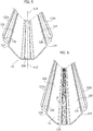
- Figure 2 is exemplary of the possibility of:
- the different reference (100 in the place of C2) used in the figures to designate the mounting member in question (which may be in fact the same type of, e.g. metal, profile used to provide the secondary support members C2) is intended to highlight the fact that, in one or more embodiments, the mounting member 100 may possibly be a different type of channel-shaped member then the members C2. Also, in one or more embodiments, the support members C2 may not exhibit a channel shape as exemplified in the figures.
- using a same type of profile for both the support members C2 and for the mounting member(s) 100 may be advantageous in so far as a single type of profile may be used for two purposes.
- Figure 2 is exemplary of the possibility of fixing the mounting member 100 onto the first support members C1, e.g. by screws 102.
- these screws may be the same type of screws used for mounting the plates or boards P1, P2 onto the support members C2 (e.g. as discussed in the following).
- Figure 2 is further exemplary of the possibility of providing (e.g. via drilling D) passageways 104 which facilitate passing towards the inner cavity of the mounting member 100 electrical wiring W from a driver unit D (power supply and, possibly, control e.g. dimming and so on) for a lighting device to be arranged at the mounting member 100 as discussed in the following.
- a driver unit D power supply and, possibly, control e.g. dimming and so on
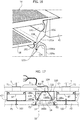
- FIG. 3 An exemplary arrangement of such a wiring W/driver circuitry D is shown in Figure 3 .
- the first array of support members C1 may lie at a distance with respect to the mounting surface S. A certain space may thus be available between the surface S and the first support members C1 for locating the driver circuitry D as well as cabling connecting one or more such units to the mains supply and/or further control systems of a lighting installation as discussed in the following.
- Figure 4 is exemplary of the possibility of installing covering plates P1, P2 by coupling them (e.g. by screws 102) to the second support members C2.
- the plates P1, P2 e.g. gypsum or plaster boards or other types of plates
- the plates P1, P2 can be coupled to the support members C2 by leaving a gap between the mutually facing edges E1, E2.
- this may occur as a result of the (rectilinear) facing edges E1, E2 of the plates P1, P2 extending at and along the side walls 100a of the mounting member 100 so that the gap between the edges E1, E2 is located at the open mouth portion 100b of the mounting member 100.
- An installation as exemplified in Figure 4 may involve some alignment of the plates P1, P2 (in both the vertical and horizontal directions of Figure 4 ) e.g. in order to adjust the width of the gap between the edges E1, E2 to adapt it precisely to the location of the side walls 100a of the mounting member 100.
- one or more embodiments may comprise provisions allowing for some (slight) inaccuracies in the mutual locations of the plates P1, P2 and the thickness thereof as well, thus making such a "fine tuning" unnecessary.
- a mounting cavity is thus provided in the mounting member 100 which is adapted to receive (see e.g. Figures 13 , 15 , 17 and 18 ) a lighting device 10 having the features discussed in the following.
- the lighting device 10 may comprise a casing in turn comprising a channel-shaped body portion 12 and a strip member 14 intended to act as a closure lid for the body 12.
- the lighting device 10 e.g. the body 12 and the closure lid 14 are exemplified in Figures 5 to 12 .
- the casing 12, 14 may comprise a sort of elastic rail design.
- the body 12 (and the casing as a whole) may comprise flexible material (such as elastic plastic material). This may facilitate a snap connection with the mounting member 100, primarily with the sidewalls 100a thereof (e.g. at the distal, hook-shaped distal ends thereof designated 1000a).
- the casing for the device 10 may comprise an elongate, channel-shaped body 12 having an inner surface inwardly of the channel shape and an outer surface outwardly of the channel shape.
- the channel-shaped body 12 may comprise a corner (or edge) portion 120 e.g. comprising a planar strip extending lengthwise of the body 12.
- the body 12 may comprise two lateral arms 122 extending from the corner portion 120 away from an intermediate longitudinal plane X12 of the body 12 (shown for simplicity in Figure 5 only).
- the lateral arms 122 have respective distal end edges 122a extending in a same direction (e.g. parallel to each other) on opposite sides of the intermediate plane X12 with an open mouth portion of the channel-shaped body 12 between the distal end edges 122a.
- the inner surface of the body 12 may comprise material and/or be treated with processes making the inner surface reflective to facilitate reflecting towards the open mouth portion of the body 12 light radiation produced by a light radiation source 16 arranged at the corner portion 120 of the body 12.
- the light radiation source 16 may comprise an elongate, electrically-powered light radiation source arranged in the body 12 of the casing extending along the corner portion 120 e.g. by being coupled (e.g. adhesively) to the inner surface of the body 12 at the corner portion 120.
- the light radiation source 16 may comprise an elongate, strip-like light radiation source.
- a flexible, ribbon-type module of the type currently referred to as "flex" and comprising light radiation sources such as LED sources is exemplary of a light radiation source 16 adapted for use in embodiments.
- Selection of the light radiation source 16 may be based e.g. on color temperature (e.g. CCT) and lumen output as desired.
- color temperature e.g. CCT
- Such a light radiation source 16 may be supplied in the form of an elongated elements wound in bobbin.
- Such a light radiation source 16 may be provided with a double-sided adhesive tape laminated on the back side of the lighting module (opposite to the location of the light radiation generators) so that the light radiation source 16 may be positioned and adhesively coupled to the corner portion 120 of the body 12, e.g. at the inner side thereof, after peeling the protective tape on the back side of the adhesive tape from the LED module.
- the body 12 (and the casing 12, 14 as a whole) may be flexible enough to fit and lock into the mounting member 100.
- the body 12 (and the casing 12, 14 as a whole) may be provided in the form of an elastic rail which may be snap-in inserted into the mounting member 100 by using a slight compressive force in the direction of the arrows of Figure 7 .
- the compressive force may bring the distal end edges 122a closer to the intermediate plane X12 and a (slight) downward insertion force (as exemplified in Figure 8 ) may lead the body 12 to be snap-in coupled mechanically (locked) with the mounting member 100.
- the body 12 (and the casing 12, 14 as a whole) may comprise plastic and/or metallic materials (possibly in the form of composite materials) having a flexibility/elasticity judiciously managed through design specifications with the possibility of making the body 12 (and the casing 12, 14 plus the radiation source 16, that is the device 10 as a whole) adapted to be accommodated into different types of mounting members 100.
- this may advantageously (yet not necessarily) have the same profile shape of the second support members C2, while the first support members C1 may adopt either the same or (as exemplified herein) a different profile.
- both profiles C1 and C2 may have a same "height" (e.g., by way of non-limiting example, 27 mm).
- coupling of the device 10 to the mounting member 100 may involve providing the body 12 of the casing of the device 10 with longitudinal snap coupling formations 124 extending lengthwise of the respective lateral arm 122 of the body 12 at a position of the outer surface of the channel-shaped body 12 between the corner portion 120 and the distal end edge 122a of the respective lateral arm.
- the coupling formations 124 may comprise longitudinal grooves capable of receiving in a snap-in coupling relationship the distal hook-shaped distal end portions 1000a of the side walls 100a of the mounting member 100.
- the coupling arrangement may be a complementary one to the one exemplified herein, namely, the outer surface of the lateral arms 122 of the body 12 can be provided with longitudinal ribs adapted to be "clutched" by the hook-shaped distal ends 1000a of the mounting member 100 or capable of extending into complementary grooves provided at the distal ends 1000a.
- Figures 10 to 12 are exemplary of ways of providing electrical connection (power supply and, possibly, control) from the driver unit D to the light radiation source 16 via the cabling W extending through the passageways 104.
- a so-called ZIF (Zero Insertion Force) connector 106 can be used for that purpose.
- end vanes or caps 108 insertable into and across the body 12 may provide end closure walls of the body 12 (notionally of indefinite length, and adapted to be cut to length by taking into account application requirements, desires or tastes).
- End vanes or caps 108 as exemplified in Figure 12 may facilitate enhanced optical efficiency (e.g. by reflective properties provided at the surface facing towards the inner space of the channel 12).
- end vanes or caps may be easily provided with slots or cutout grooves 108a to facilitate passing electrical wiring W therethrough.
- One or more embodiments may provide for the presence of distal coupling formations 126 extending lengthwise of the lateral arms 122 of the body 12 at the distal end edges 122a in order to facilitate coupling with the closure lid 14 of the casing.
- the distal coupling formations 126 may comprise longitudinal grooves formed along the distal end edges 122a facing inwardly of the channel shape of the body 12.
- the formations 126 are adapted to receive engaged therein complementarily formations such as e.g. protruding ribs 142 provided along the side edges of the closure lid 14.
- Coupling of the formations 126, 142 may thus occur at the region between the longitudinal edges E1, E2 of the plates P1, P2, the end margins 1000a of the sidewalls 100a of the mounting member 100 and the distal end edges 122a of the lateral arms 122 of the body 12.
- the formations 126, 142 facilitate applying the closure lid 14 onto the open mouth portion of the channel-shaped body 12, thus facilitating closing the gap between the mutually facing (and spaced apart) edges E1, E2 of the plates P1, P2.
- coupling between the complementary formations 126, 142 of the body 12 and the closure lid 14 may be provided with some play adapted to allow for possible slight misalignments of the plates P1, P2 (e.g. in the "vertical" direction of Figure 4 ).
- the view of Figure 14 highlights the possibility for the closure lid 14 to comprise protruding side portions 144 which protrude outwardly of the distal end edges 122a of the lateral arms 122 of the body 12 with the capability of extending towards and over the end edges E1 and E2 (the end edge E2 is shown in Figure 14 by way of example) in order to facilitate covering any gap G between the distal edges 122a and the facing edges E1, E2 of the plates P1, P2.
- the one shown in the figures is just one of a variety of coupling options of the body 12 and the closure lid 14.
- the coupling arrangement may be a complementary one to the one exemplified herein, namely, the distal end edges 122a of the lateral arms 122 of the body 12 can be provided with longitudinal ribs adapted to be received in longitudinal grooves extending along the sides of the closure lid 14.
- the closure lid 14 may comprise material which is light-permeable by being transparent and/or diffusive.
- the closure lid 14 may exhibit optical features (e.g. surface sculpturing) with the lid 14 playing the role of a so-called secondary-optics in the installation, a primary optics being possibly provided by the reflective inner surfaces of the lateral arms 122 of the body 12.
- the closure lid 14 can be manufactured as a flexible strip using a roll-to-roll process e.g. with the sufficient thickness of plastic material to make it rollable.
- the corresponding optical features may be designed according to any known principles (small prisms, lenslets and the like) e.g. to provide shaping/diffusion of the light radiation emitted from the device and/or UGR control and lighting uniformity.
- Figures 16 and 17 exemplify the possibility, for one or more embodiments, to comprise a "tertiary" optics in the lighting device 10 by providing in the lateral arms 122 of the body 12 further longitudinal coupling formations 128 extending lengthwise of the lateral arms 122 of the body 12 at a position of the inner surface of the body 12 between the corner or edge portion 120 and the distal end edges 122a of the lateral arms 122.
- a strip-like (e.g. flexible) optical element 18 may then be provided having side edges coupleable (e.g. via formations 182) with the further longitudinal coupling formations 128 so that the optical element 18 may extend bridge-like between the lateral arms 122 of the channel-shaped body 12 between the corner portion 120 and a distal end edges 122a.
- the further longitudinal coupling formations 128 may be provided in the form of longitudinal grooves extending along the inner surface of the lateral arms 122 while the complementary formations 182 of the optical element 18 comprise hook-like ribs capable of extending into the grooves 128 thereby facilitating e.g. snap-in coupling of the optical element 18 (possibly again of the flexible type) with the body 12.
- a complementary coupling arrangement may be provided between the optical element 18 and the body 12.
- the optical element 18 may comprise optical features (e.g. a prismed lens or distribution of lenslets) to enhance the lighting output e.g. in terms of lighting uniformity.
- optical features e.g. a prismed lens or distribution of lenslets
- the combination of a primary optics (reflective inner surfaces of the body 12), a secondary optics (the closure lid 14) and a tertiary optics (optical element 18) may result in improvements in UGR control and lighting uniformity. It will be otherwise appreciated that use of all of the primary, secondary and tertiary optics in combination is optional and not mandatory.
- Figure 18 (which substantially corresponds to Figure 17 in so far as the parts or elements described therein are concerned) is exemplary of an approach allowing for possible variations in the thicknesses of the cover plates P1, P2.
- a typical thickness value for gypsum or plaster boards may be about 9.5 mm.
- plate thickness may vary, for instance (in the case of a gypsum boards), to values such as 12.5 mm, 15mm and 18 mm.
- Figure 18 may refer to embodiments wherein the various parts or elements of the device 10 and/or the mounting member 100 are shaped and dimensioned with reference to a lowest expected thickness value for the boards P1, P2.
- spacers 130 may be provided between the mounting member 100 and the first support members C1 to accommodate other (larger) thickness options, without this involving re-design of the various components.
- electrically-insulating spacers 130 coupled via electrically-insulating coupling means (e.g. screws 102) to the corner portion 120 at the outer surface of the body 12 may provide, possibly together with heat-dissipation from the light radiation source 16, (bi-directional) electrical insulation of the device 10 with respect to a grid comprising electrically conductive (e.g. metal) support members C1 (and C2).
- electrically conductive e.g. metal
- the body 12 may comprise electrically-conductive material (e.g. metal) and be exposed to touch by users.
- Figure 19 is exemplary of the possibility that the distal coupling formations 126 of the side walls 122 and/or the lateral coupling formations 142 of the closure lid 14 may comprise a plurality of individual coupling members providing a corresponding plurality of selectable coupling positions of the closure lid 14 to the channel-shaped body 12 at different distances (of the closure lid 14) to the corner portion 120 of the channel-shaped body 12.
- Figure 19 exemplifies the possibility of so-to-say partitioning the grooves 126 in a set of e.g. two or more sub-grooves 1260 (e.g. four of them) so that the protruding formations 142 from the closure lid 14 may be engaged in a selected one of these sub-grooves (e.g. in an uppermost position as exemplified in portion a) of the Figure 19 , a lowermost position as exemplified in portion c) of Figure 19 or an intermediate position as exemplified in portion b) in Figure 19 ).
- a set of e.g. two or more sub-grooves 1260 e.g. four of them
- a casing according to one or more embodiments (and a lighting device comprising such a casing with an elongate, electrically-powered light radiation source e.g. 16 arranged in the casing extending along the corner portion of the channel-shaped body) may be suited for use in a method according to one or more embodiments, wherein the method may comprise:
- a casing according to one or more embodiments (and a lighting device comprising such a casing with an elongate, electrically-powered light radiation source e.g. 16 arranged in the casing extending along the corner portion of the channel-shaped body) may be suited for use in an installation according to one or more embodiments, wherein the installation may comprise:
- the closure lid may comprise protruding side formations (e.g. 144) which, with the closure lid coupled to the lateral arms of the channel-shaped body to close the open mouth portion of the body, protrude outwardly of the distal end edges (122a) of the lateral arms of the channel-shaped body.
- the distal coupling formations of the channel-shaped body and the lateral coupling formations of the closure lid may comprise a plurality of individual coupling members (e.g. 1260) providing a plurality of selectable coupling positions of the closure lid to the channel-shaped body at different distances from the corner portion of the channel-shaped body.
- the intermediate longitudinal plane (e.g. X12) may comprise a median longitudinal plane of the channel-shaped body with the two lateral arms mirror-symmetrical with respect to the median longitudinal plane.
- the lateral arms of the channel-shaped body may be elastically deformable towards and away from the intermediate longitudinal plane.
- One or more embodiments of the casing may comprise a light-reflective inner surface of the channel-shaped body.
- One or more embodiments may include at least one electrically-insulating spacer (e.g. 130) coupleable with electrically-insulating coupling means (e.g. 102 in Figure 18 ) to the corner portion of the body at the outer surface thereof.
- electrically-insulating spacer e.g. 130
- electrically-insulating coupling means e.g. 102 in Figure 18
- the method of one or more embodiments may comprise arranging the lighting device in the inner cavity of the mounting member by snap-engaging the longitudinal snap coupling formations of the lateral arms of the channel-shaped body of the casing of the lighting device with the side walls of the channel-shaped mounting member.
Applications Claiming Priority (1)
| Application Number | Priority Date | Filing Date | Title |
|---|---|---|---|
| IT201700129055 | 2017-11-13 |
Publications (2)
| Publication Number | Publication Date |
|---|---|
| EP3483497A1 true EP3483497A1 (de) | 2019-05-15 |
| EP3483497B1 EP3483497B1 (de) | 2020-04-22 |
Family
ID=61224451
Family Applications (1)
| Application Number | Title | Priority Date | Filing Date |
|---|---|---|---|
| EP18204518.7A Active EP3483497B1 (de) | 2017-11-13 | 2018-11-06 | Beleuchtungsanlage und verfahren |
Country Status (1)
| Country | Link |
|---|---|
| EP (1) | EP3483497B1 (de) |
Families Citing this family (1)
| Publication number | Priority date | Publication date | Assignee | Title |
|---|---|---|---|---|
| RU200910U1 (ru) * | 2020-06-12 | 2020-11-18 | Общество с ограниченной ответственностью "Ледел" | Светодиодное осветительное устройство |
Citations (6)
| Publication number | Priority date | Publication date | Assignee | Title |
|---|---|---|---|---|
| DE202015101755U1 (de) * | 2015-04-10 | 2015-05-04 | Osram Gmbh | Flexible Leuchtenanordnung für gekrümmte Vouten |
| US20150260354A1 (en) * | 2014-03-12 | 2015-09-17 | H4X E.U. | Planar strip light for installation in a plasterboard construction |
| US20150330595A1 (en) * | 2014-05-15 | 2015-11-19 | Valerica Grigore | Linear lighting systems, manufacturing and methods to configure the same |
| EP3023692A1 (de) * | 2014-11-21 | 2016-05-25 | Belfiore s.r.l. | Struktur für durchgehende lineare lichtöffnungen in decken und wänden |
| US20170102133A1 (en) * | 2014-04-28 | 2017-04-13 | Zumtobel Lighting Gmbh | Arrangement for Forming an Elongate, Channel-Type Accommodation Space |
| US20170122509A1 (en) * | 2014-04-28 | 2017-05-04 | Zumtobel Lighting Gmbh | Light Strip System |
-
2018
- 2018-11-06 EP EP18204518.7A patent/EP3483497B1/de active Active
Patent Citations (6)
| Publication number | Priority date | Publication date | Assignee | Title |
|---|---|---|---|---|
| US20150260354A1 (en) * | 2014-03-12 | 2015-09-17 | H4X E.U. | Planar strip light for installation in a plasterboard construction |
| US20170102133A1 (en) * | 2014-04-28 | 2017-04-13 | Zumtobel Lighting Gmbh | Arrangement for Forming an Elongate, Channel-Type Accommodation Space |
| US20170122509A1 (en) * | 2014-04-28 | 2017-05-04 | Zumtobel Lighting Gmbh | Light Strip System |
| US20150330595A1 (en) * | 2014-05-15 | 2015-11-19 | Valerica Grigore | Linear lighting systems, manufacturing and methods to configure the same |
| EP3023692A1 (de) * | 2014-11-21 | 2016-05-25 | Belfiore s.r.l. | Struktur für durchgehende lineare lichtöffnungen in decken und wänden |
| DE202015101755U1 (de) * | 2015-04-10 | 2015-05-04 | Osram Gmbh | Flexible Leuchtenanordnung für gekrümmte Vouten |
Also Published As
| Publication number | Publication date |
|---|---|
| EP3483497B1 (de) | 2020-04-22 |
Similar Documents
| Publication | Publication Date | Title |
|---|---|---|
| US9004718B2 (en) | LED decorative illuminated trim system | |
| US9140436B2 (en) | Configurable ceiling lighting system | |
| US10006592B2 (en) | LED lighting system with distributive powering scheme | |
| US20130083514A1 (en) | Lighting assembly for ceiling board | |
| US9388969B2 (en) | Lighting system for an architectural surface structure | |
| US8109659B2 (en) | Lighting fixture for an architectural surface structure | |
| US11396751B2 (en) | Ceiling grid lighting assembly with linear lighting modules in parallel arrangement | |
| US20130308303A1 (en) | Lighting System for an Architectural Ceiling Structure | |
| US10563829B2 (en) | Fastening device and a system for fastening lighting devices to a false ceiling | |
| US9551469B2 (en) | Linear lighting systems, manufacturing and methods to configure the same | |
| US10125933B1 (en) | Curved recessed supporting device for installation of LED illuminating devices in walls and ceilings | |
| CA2899063A1 (en) | Elongated l.e.d. lighting systems, manufacturing and methods to configure the same | |
| EP3483497B1 (de) | Beleuchtungsanlage und verfahren | |
| US9851093B2 (en) | Elongated L.E.D. lighting systems, manufacturing and methods to configure the same | |
| US9951915B2 (en) | Planar strip light for installation in a plasterboard construction | |
| US20240027039A1 (en) | Lighting devices for ceiling grids | |
| CN208718266U (zh) | 一种用于室内设计的装饰墙板 | |
| WO2009122325A1 (en) | Tile spacer | |
| US20210381665A1 (en) | Lighting Device for a False Ceiling, False Ceiling Comprising Such Lighting Device and Method for Fitting Such Lighting Device | |
| JP2015032404A (ja) | 連結用照明装置 | |
| US10297996B1 (en) | Reversible junction box cover | |
| EP2577152A2 (de) | Beleuchtungsanordnung für ein deckenbrett | |
| US20220333765A1 (en) | Configurable Ceiling Grid Lighting Assembly with T-Bar Mounting | |
| US20220373144A1 (en) | Light fixture and light fixture assemblies with electrically controlled lighting distributions for installed panel systems | |
| RU207671U1 (ru) | Встроенный теневой плинтус |
Legal Events
| Date | Code | Title | Description |
|---|---|---|---|
| PUAI | Public reference made under article 153(3) epc to a published international application that has entered the european phase |
Free format text: ORIGINAL CODE: 0009012 |
|
| STAA | Information on the status of an ep patent application or granted ep patent |
Free format text: STATUS: THE APPLICATION HAS BEEN PUBLISHED |
|
| AK | Designated contracting states |
Kind code of ref document: A1 Designated state(s): AL AT BE BG CH CY CZ DE DK EE ES FI FR GB GR HR HU IE IS IT LI LT LU LV MC MK MT NL NO PL PT RO RS SE SI SK SM TR |
|
| AX | Request for extension of the european patent |
Extension state: BA ME |
|
| STAA | Information on the status of an ep patent application or granted ep patent |
Free format text: STATUS: REQUEST FOR EXAMINATION WAS MADE |
|
| 17P | Request for examination filed |
Effective date: 20191002 |
|
| GRAP | Despatch of communication of intention to grant a patent |
Free format text: ORIGINAL CODE: EPIDOSNIGR1 |
|
| RBV | Designated contracting states (corrected) |
Designated state(s): AL AT BE BG CH CY CZ DE DK EE ES FI FR GB GR HR HU IE IS IT LI LT LU LV MC MK MT NL NO PL PT RO RS SE SI SK SM TR |
|
| STAA | Information on the status of an ep patent application or granted ep patent |
Free format text: STATUS: GRANT OF PATENT IS INTENDED |
|
| RIC1 | Information provided on ipc code assigned before grant |
Ipc: F21S 8/02 20060101AFI20191014BHEP Ipc: F21Y 115/10 20160101ALN20191014BHEP Ipc: E04B 9/00 20060101ALI20191014BHEP Ipc: F21Y 103/10 20160101ALN20191014BHEP Ipc: F21V 17/16 20060101ALI20191014BHEP Ipc: F21V 21/04 20060101ALI20191014BHEP Ipc: F21S 4/22 20160101ALI20191014BHEP |
|
| INTG | Intention to grant announced |
Effective date: 20191107 |
|
| GRAS | Grant fee paid |
Free format text: ORIGINAL CODE: EPIDOSNIGR3 |
|
| GRAA | (expected) grant |
Free format text: ORIGINAL CODE: 0009210 |
|
| STAA | Information on the status of an ep patent application or granted ep patent |
Free format text: STATUS: THE PATENT HAS BEEN GRANTED |
|
| AK | Designated contracting states |
Kind code of ref document: B1 Designated state(s): AL AT BE BG CH CY CZ DE DK EE ES FI FR GB GR HR HU IE IS IT LI LT LU LV MC MK MT NL NO PL PT RO RS SE SI SK SM TR |
|
| REG | Reference to a national code |
Ref country code: CH Ref legal event code: EP |
|
| REG | Reference to a national code |
Ref country code: IE Ref legal event code: FG4D |
|
| REG | Reference to a national code |
Ref country code: DE Ref legal event code: R096 Ref document number: 602018003985 Country of ref document: DE |
|
| REG | Reference to a national code |
Ref country code: AT Ref legal event code: REF Ref document number: 1260582 Country of ref document: AT Kind code of ref document: T Effective date: 20200515 |
|
| REG | Reference to a national code |
Ref country code: LT Ref legal event code: MG4D |
|
| REG | Reference to a national code |
Ref country code: NL Ref legal event code: MP Effective date: 20200422 |
|
| RAP2 | Party data changed (patent owner data changed or rights of a patent transferred) |
Owner name: OSRAM S.P.A. - SOCIETA' RIUNITE OSRAM EDISON CLERICI Owner name: OSRAM GMBH |
|
| PG25 | Lapsed in a contracting state [announced via postgrant information from national office to epo] |
Ref country code: NL Free format text: LAPSE BECAUSE OF FAILURE TO SUBMIT A TRANSLATION OF THE DESCRIPTION OR TO PAY THE FEE WITHIN THE PRESCRIBED TIME-LIMIT Effective date: 20200422 Ref country code: LT Free format text: LAPSE BECAUSE OF FAILURE TO SUBMIT A TRANSLATION OF THE DESCRIPTION OR TO PAY THE FEE WITHIN THE PRESCRIBED TIME-LIMIT Effective date: 20200422 Ref country code: PT Free format text: LAPSE BECAUSE OF FAILURE TO SUBMIT A TRANSLATION OF THE DESCRIPTION OR TO PAY THE FEE WITHIN THE PRESCRIBED TIME-LIMIT Effective date: 20200824 Ref country code: GR Free format text: LAPSE BECAUSE OF FAILURE TO SUBMIT A TRANSLATION OF THE DESCRIPTION OR TO PAY THE FEE WITHIN THE PRESCRIBED TIME-LIMIT Effective date: 20200723 Ref country code: SE Free format text: LAPSE BECAUSE OF FAILURE TO SUBMIT A TRANSLATION OF THE DESCRIPTION OR TO PAY THE FEE WITHIN THE PRESCRIBED TIME-LIMIT Effective date: 20200422 Ref country code: NO Free format text: LAPSE BECAUSE OF FAILURE TO SUBMIT A TRANSLATION OF THE DESCRIPTION OR TO PAY THE FEE WITHIN THE PRESCRIBED TIME-LIMIT Effective date: 20200722 Ref country code: IS Free format text: LAPSE BECAUSE OF FAILURE TO SUBMIT A TRANSLATION OF THE DESCRIPTION OR TO PAY THE FEE WITHIN THE PRESCRIBED TIME-LIMIT Effective date: 20200822 Ref country code: FI Free format text: LAPSE BECAUSE OF FAILURE TO SUBMIT A TRANSLATION OF THE DESCRIPTION OR TO PAY THE FEE WITHIN THE PRESCRIBED TIME-LIMIT Effective date: 20200422 |
|
| REG | Reference to a national code |
Ref country code: AT Ref legal event code: MK05 Ref document number: 1260582 Country of ref document: AT Kind code of ref document: T Effective date: 20200422 |
|
| PG25 | Lapsed in a contracting state [announced via postgrant information from national office to epo] |
Ref country code: RS Free format text: LAPSE BECAUSE OF FAILURE TO SUBMIT A TRANSLATION OF THE DESCRIPTION OR TO PAY THE FEE WITHIN THE PRESCRIBED TIME-LIMIT Effective date: 20200422 Ref country code: HR Free format text: LAPSE BECAUSE OF FAILURE TO SUBMIT A TRANSLATION OF THE DESCRIPTION OR TO PAY THE FEE WITHIN THE PRESCRIBED TIME-LIMIT Effective date: 20200422 Ref country code: BG Free format text: LAPSE BECAUSE OF FAILURE TO SUBMIT A TRANSLATION OF THE DESCRIPTION OR TO PAY THE FEE WITHIN THE PRESCRIBED TIME-LIMIT Effective date: 20200722 Ref country code: LV Free format text: LAPSE BECAUSE OF FAILURE TO SUBMIT A TRANSLATION OF THE DESCRIPTION OR TO PAY THE FEE WITHIN THE PRESCRIBED TIME-LIMIT Effective date: 20200422 |
|
| PG25 | Lapsed in a contracting state [announced via postgrant information from national office to epo] |
Ref country code: AL Free format text: LAPSE BECAUSE OF FAILURE TO SUBMIT A TRANSLATION OF THE DESCRIPTION OR TO PAY THE FEE WITHIN THE PRESCRIBED TIME-LIMIT Effective date: 20200422 |
|
| REG | Reference to a national code |
Ref country code: DE Ref legal event code: R097 Ref document number: 602018003985 Country of ref document: DE |
|
| PG25 | Lapsed in a contracting state [announced via postgrant information from national office to epo] |
Ref country code: EE Free format text: LAPSE BECAUSE OF FAILURE TO SUBMIT A TRANSLATION OF THE DESCRIPTION OR TO PAY THE FEE WITHIN THE PRESCRIBED TIME-LIMIT Effective date: 20200422 Ref country code: SM Free format text: LAPSE BECAUSE OF FAILURE TO SUBMIT A TRANSLATION OF THE DESCRIPTION OR TO PAY THE FEE WITHIN THE PRESCRIBED TIME-LIMIT Effective date: 20200422 Ref country code: AT Free format text: LAPSE BECAUSE OF FAILURE TO SUBMIT A TRANSLATION OF THE DESCRIPTION OR TO PAY THE FEE WITHIN THE PRESCRIBED TIME-LIMIT Effective date: 20200422 Ref country code: RO Free format text: LAPSE BECAUSE OF FAILURE TO SUBMIT A TRANSLATION OF THE DESCRIPTION OR TO PAY THE FEE WITHIN THE PRESCRIBED TIME-LIMIT Effective date: 20200422 Ref country code: CZ Free format text: LAPSE BECAUSE OF FAILURE TO SUBMIT A TRANSLATION OF THE DESCRIPTION OR TO PAY THE FEE WITHIN THE PRESCRIBED TIME-LIMIT Effective date: 20200422 Ref country code: ES Free format text: LAPSE BECAUSE OF FAILURE TO SUBMIT A TRANSLATION OF THE DESCRIPTION OR TO PAY THE FEE WITHIN THE PRESCRIBED TIME-LIMIT Effective date: 20200422 Ref country code: IT Free format text: LAPSE BECAUSE OF FAILURE TO SUBMIT A TRANSLATION OF THE DESCRIPTION OR TO PAY THE FEE WITHIN THE PRESCRIBED TIME-LIMIT Effective date: 20200422 Ref country code: DK Free format text: LAPSE BECAUSE OF FAILURE TO SUBMIT A TRANSLATION OF THE DESCRIPTION OR TO PAY THE FEE WITHIN THE PRESCRIBED TIME-LIMIT Effective date: 20200422 |
|
| PG25 | Lapsed in a contracting state [announced via postgrant information from national office to epo] |
Ref country code: SK Free format text: LAPSE BECAUSE OF FAILURE TO SUBMIT A TRANSLATION OF THE DESCRIPTION OR TO PAY THE FEE WITHIN THE PRESCRIBED TIME-LIMIT Effective date: 20200422 Ref country code: PL Free format text: LAPSE BECAUSE OF FAILURE TO SUBMIT A TRANSLATION OF THE DESCRIPTION OR TO PAY THE FEE WITHIN THE PRESCRIBED TIME-LIMIT Effective date: 20200422 |
|
| PLBE | No opposition filed within time limit |
Free format text: ORIGINAL CODE: 0009261 |
|
| STAA | Information on the status of an ep patent application or granted ep patent |
Free format text: STATUS: NO OPPOSITION FILED WITHIN TIME LIMIT |
|
| 26N | No opposition filed |
Effective date: 20210125 |
|
| PG25 | Lapsed in a contracting state [announced via postgrant information from national office to epo] |
Ref country code: SI Free format text: LAPSE BECAUSE OF FAILURE TO SUBMIT A TRANSLATION OF THE DESCRIPTION OR TO PAY THE FEE WITHIN THE PRESCRIBED TIME-LIMIT Effective date: 20200422 |
|
| PG25 | Lapsed in a contracting state [announced via postgrant information from national office to epo] |
Ref country code: MC Free format text: LAPSE BECAUSE OF FAILURE TO SUBMIT A TRANSLATION OF THE DESCRIPTION OR TO PAY THE FEE WITHIN THE PRESCRIBED TIME-LIMIT Effective date: 20200422 |
|
| PG25 | Lapsed in a contracting state [announced via postgrant information from national office to epo] |
Ref country code: LU Free format text: LAPSE BECAUSE OF NON-PAYMENT OF DUE FEES Effective date: 20201106 |
|
| REG | Reference to a national code |
Ref country code: BE Ref legal event code: MM Effective date: 20201130 |
|
| PG25 | Lapsed in a contracting state [announced via postgrant information from national office to epo] |
Ref country code: FR Free format text: LAPSE BECAUSE OF NON-PAYMENT OF DUE FEES Effective date: 20201130 Ref country code: IE Free format text: LAPSE BECAUSE OF NON-PAYMENT OF DUE FEES Effective date: 20201106 |
|
| PG25 | Lapsed in a contracting state [announced via postgrant information from national office to epo] |
Ref country code: TR Free format text: LAPSE BECAUSE OF FAILURE TO SUBMIT A TRANSLATION OF THE DESCRIPTION OR TO PAY THE FEE WITHIN THE PRESCRIBED TIME-LIMIT Effective date: 20200422 Ref country code: MT Free format text: LAPSE BECAUSE OF FAILURE TO SUBMIT A TRANSLATION OF THE DESCRIPTION OR TO PAY THE FEE WITHIN THE PRESCRIBED TIME-LIMIT Effective date: 20200422 Ref country code: CY Free format text: LAPSE BECAUSE OF FAILURE TO SUBMIT A TRANSLATION OF THE DESCRIPTION OR TO PAY THE FEE WITHIN THE PRESCRIBED TIME-LIMIT Effective date: 20200422 |
|
| PG25 | Lapsed in a contracting state [announced via postgrant information from national office to epo] |
Ref country code: MK Free format text: LAPSE BECAUSE OF FAILURE TO SUBMIT A TRANSLATION OF THE DESCRIPTION OR TO PAY THE FEE WITHIN THE PRESCRIBED TIME-LIMIT Effective date: 20200422 |
|
| REG | Reference to a national code |
Ref country code: CH Ref legal event code: PL |
|
| PG25 | Lapsed in a contracting state [announced via postgrant information from national office to epo] |
Ref country code: BE Free format text: LAPSE BECAUSE OF NON-PAYMENT OF DUE FEES Effective date: 20201130 |
|
| PG25 | Lapsed in a contracting state [announced via postgrant information from national office to epo] |
Ref country code: LI Free format text: LAPSE BECAUSE OF NON-PAYMENT OF DUE FEES Effective date: 20211130 Ref country code: CH Free format text: LAPSE BECAUSE OF NON-PAYMENT OF DUE FEES Effective date: 20211130 |
|
| REG | Reference to a national code |
Ref country code: DE Ref legal event code: R081 Ref document number: 602018003985 Country of ref document: DE Owner name: OPTOTRONIC GMBH, DE Free format text: FORMER OWNER: OSRAM GMBH, 80807 MUENCHEN, DE |
|
| GBPC | Gb: european patent ceased through non-payment of renewal fee |
Effective date: 20221106 |
|
| PG25 | Lapsed in a contracting state [announced via postgrant information from national office to epo] |
Ref country code: GB Free format text: LAPSE BECAUSE OF NON-PAYMENT OF DUE FEES Effective date: 20221106 |
|
| PGFP | Annual fee paid to national office [announced via postgrant information from national office to epo] |
Ref country code: DE Payment date: 20231120 Year of fee payment: 6 |