EP3483480A1 - Hydraulic control device for a vehicle - Google Patents
Hydraulic control device for a vehicle Download PDFInfo
- Publication number
- EP3483480A1 EP3483480A1 EP18204898.3A EP18204898A EP3483480A1 EP 3483480 A1 EP3483480 A1 EP 3483480A1 EP 18204898 A EP18204898 A EP 18204898A EP 3483480 A1 EP3483480 A1 EP 3483480A1
- Authority
- EP
- European Patent Office
- Prior art keywords
- cam
- control device
- actuating lever
- hydraulic control
- motor
- Prior art date
- Legal status (The legal status is an assumption and is not a legal conclusion. Google has not performed a legal analysis and makes no representation as to the accuracy of the status listed.)
- Granted
Links
Images





Classifications
-
- F—MECHANICAL ENGINEERING; LIGHTING; HEATING; WEAPONS; BLASTING
- F16—ENGINEERING ELEMENTS AND UNITS; GENERAL MEASURES FOR PRODUCING AND MAINTAINING EFFECTIVE FUNCTIONING OF MACHINES OR INSTALLATIONS; THERMAL INSULATION IN GENERAL
- F16H—GEARING
- F16H61/00—Control functions within control units of change-speed- or reversing-gearings for conveying rotary motion ; Control of exclusively fluid gearing, friction gearing, gearings with endless flexible members or other particular types of gearing
- F16H61/0021—Generation or control of line pressure
- F16H61/0025—Supply of control fluid; Pumps therefor
- F16H61/0031—Supply of control fluid; Pumps therefor using auxiliary pumps, e.g. pump driven by a different power source than the engine
-
- B—PERFORMING OPERATIONS; TRANSPORTING
- B60—VEHICLES IN GENERAL
- B60T—VEHICLE BRAKE CONTROL SYSTEMS OR PARTS THEREOF; BRAKE CONTROL SYSTEMS OR PARTS THEREOF, IN GENERAL; ARRANGEMENT OF BRAKING ELEMENTS ON VEHICLES IN GENERAL; PORTABLE DEVICES FOR PREVENTING UNWANTED MOVEMENT OF VEHICLES; VEHICLE MODIFICATIONS TO FACILITATE COOLING OF BRAKES
- B60T13/00—Transmitting braking action from initiating means to ultimate brake actuator with power assistance or drive; Brake systems incorporating such transmitting means, e.g. air-pressure brake systems
- B60T13/74—Transmitting braking action from initiating means to ultimate brake actuator with power assistance or drive; Brake systems incorporating such transmitting means, e.g. air-pressure brake systems with electrical assistance or drive
- B60T13/745—Transmitting braking action from initiating means to ultimate brake actuator with power assistance or drive; Brake systems incorporating such transmitting means, e.g. air-pressure brake systems with electrical assistance or drive acting on a hydraulic system, e.g. a master cylinder
-
- F—MECHANICAL ENGINEERING; LIGHTING; HEATING; WEAPONS; BLASTING
- F16—ENGINEERING ELEMENTS AND UNITS; GENERAL MEASURES FOR PRODUCING AND MAINTAINING EFFECTIVE FUNCTIONING OF MACHINES OR INSTALLATIONS; THERMAL INSULATION IN GENERAL
- F16D—COUPLINGS FOR TRANSMITTING ROTATION; CLUTCHES; BRAKES
- F16D65/00—Parts or details
- F16D65/14—Actuating mechanisms for brakes; Means for initiating operation at a predetermined position
- F16D65/28—Actuating mechanisms for brakes; Means for initiating operation at a predetermined position arranged apart from the brake
-
- B—PERFORMING OPERATIONS; TRANSPORTING
- B60—VEHICLES IN GENERAL
- B60G—VEHICLE SUSPENSION ARRANGEMENTS
- B60G2202/00—Indexing codes relating to the type of spring, damper or actuator
- B60G2202/40—Type of actuator
- B60G2202/41—Fluid actuator
- B60G2202/413—Hydraulic actuator
-
- B—PERFORMING OPERATIONS; TRANSPORTING
- B60—VEHICLES IN GENERAL
- B60G—VEHICLE SUSPENSION ARRANGEMENTS
- B60G2202/00—Indexing codes relating to the type of spring, damper or actuator
- B60G2202/40—Type of actuator
- B60G2202/41—Fluid actuator
- B60G2202/416—Fluid actuator using a pump, e.g. in the line connecting the lower chamber to the upper chamber of the actuator
-
- F—MECHANICAL ENGINEERING; LIGHTING; HEATING; WEAPONS; BLASTING
- F16—ENGINEERING ELEMENTS AND UNITS; GENERAL MEASURES FOR PRODUCING AND MAINTAINING EFFECTIVE FUNCTIONING OF MACHINES OR INSTALLATIONS; THERMAL INSULATION IN GENERAL
- F16D—COUPLINGS FOR TRANSMITTING ROTATION; CLUTCHES; BRAKES
- F16D2121/00—Type of actuator operation force
- F16D2121/02—Fluid pressure
- F16D2121/04—Fluid pressure acting on a piston-type actuator, e.g. for liquid pressure
-
- F—MECHANICAL ENGINEERING; LIGHTING; HEATING; WEAPONS; BLASTING
- F16—ENGINEERING ELEMENTS AND UNITS; GENERAL MEASURES FOR PRODUCING AND MAINTAINING EFFECTIVE FUNCTIONING OF MACHINES OR INSTALLATIONS; THERMAL INSULATION IN GENERAL
- F16D—COUPLINGS FOR TRANSMITTING ROTATION; CLUTCHES; BRAKES
- F16D2125/00—Components of actuators
- F16D2125/18—Mechanical mechanisms
- F16D2125/20—Mechanical mechanisms converting rotation to linear movement or vice versa
- F16D2125/22—Mechanical mechanisms converting rotation to linear movement or vice versa acting transversely to the axis of rotation
- F16D2125/28—Cams; Levers with cams
-
- F—MECHANICAL ENGINEERING; LIGHTING; HEATING; WEAPONS; BLASTING
- F16—ENGINEERING ELEMENTS AND UNITS; GENERAL MEASURES FOR PRODUCING AND MAINTAINING EFFECTIVE FUNCTIONING OF MACHINES OR INSTALLATIONS; THERMAL INSULATION IN GENERAL
- F16D—COUPLINGS FOR TRANSMITTING ROTATION; CLUTCHES; BRAKES
- F16D2125/00—Components of actuators
- F16D2125/18—Mechanical mechanisms
- F16D2125/44—Mechanical mechanisms transmitting rotation
- F16D2125/46—Rotating members in mutual engagement
- F16D2125/48—Rotating members in mutual engagement with parallel stationary axes, e.g. spur gears
-
- F—MECHANICAL ENGINEERING; LIGHTING; HEATING; WEAPONS; BLASTING
- F16—ENGINEERING ELEMENTS AND UNITS; GENERAL MEASURES FOR PRODUCING AND MAINTAINING EFFECTIVE FUNCTIONING OF MACHINES OR INSTALLATIONS; THERMAL INSULATION IN GENERAL
- F16D—COUPLINGS FOR TRANSMITTING ROTATION; CLUTCHES; BRAKES
- F16D2125/00—Components of actuators
- F16D2125/18—Mechanical mechanisms
- F16D2125/44—Mechanical mechanisms transmitting rotation
- F16D2125/46—Rotating members in mutual engagement
- F16D2125/52—Rotating members in mutual engagement with non-parallel stationary axes, e.g. worm or bevel gears
-
- F—MECHANICAL ENGINEERING; LIGHTING; HEATING; WEAPONS; BLASTING
- F16—ENGINEERING ELEMENTS AND UNITS; GENERAL MEASURES FOR PRODUCING AND MAINTAINING EFFECTIVE FUNCTIONING OF MACHINES OR INSTALLATIONS; THERMAL INSULATION IN GENERAL
- F16D—COUPLINGS FOR TRANSMITTING ROTATION; CLUTCHES; BRAKES
- F16D2125/00—Components of actuators
- F16D2125/18—Mechanical mechanisms
- F16D2125/58—Mechanical mechanisms transmitting linear movement
- F16D2125/60—Cables or chains, e.g. Bowden cables
-
- F—MECHANICAL ENGINEERING; LIGHTING; HEATING; WEAPONS; BLASTING
- F16—ENGINEERING ELEMENTS AND UNITS; GENERAL MEASURES FOR PRODUCING AND MAINTAINING EFFECTIVE FUNCTIONING OF MACHINES OR INSTALLATIONS; THERMAL INSULATION IN GENERAL
- F16D—COUPLINGS FOR TRANSMITTING ROTATION; CLUTCHES; BRAKES
- F16D2125/00—Components of actuators
- F16D2125/18—Mechanical mechanisms
- F16D2125/58—Mechanical mechanisms transmitting linear movement
- F16D2125/64—Levers
Definitions
- the disclosure relates to a hydraulic system for a vehicle, and more particularly to a hydraulic control device for a straddle type vehicle that provides a pressurized hydraulic fluid to a hydraulic fluid circuit and is to be directed to different subsystems.
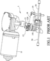
- a known selective actuation device 1 for a vehicle disclosed in EP 1562098 includes an actuator 11 acting upon an actuation lever 14.
- the actuation lever 14 has a thruster element 141 for the actuation of a first operating group represented by an oil pump 16 which, in acting upon a hydraulic circuit 15, in turn activates a locking device 17 of an anti-rolling system and stroke stop devices 18, 18' of front suspensions.
- a cam element 19 is movable by the actuation lever 14 between an activation position in which the cam element 19 acts upon a second operating group represented by a cable 20 to actuate a rear brake of the vehicle, and a rest position in which the activation of the first operating group is disassociated from the second operating group.
- the actuator 11, through a worm screw acts upon an adapted pinion 12, which makes gears 120, 13 rotated.
- an object of the disclosure is to provide a hydraulic control device that can alleviate at least one of the drawbacks of the prior art.
- the hydraulic control device is for connecting with a hydraulic fluid circuit of a vehicle, and includes a housing, an actuator, a main pump mechanically actuated to create a fluid pressure or provide a pressurized hydraulic fluid to the hydraulic fluid circuit, an actuating lever having an end which is connected with the main pump, a thrust member rotatably mounted on an opposite end of the actuating lever about a thrust rotation center, and a cam rotatably mounted on the housing and actuated by the actuator to be rotated about a cam rotation center.
- the cam is configured to be in sliding contact with the thrust member to rotate the thrust member about the thrust rotation center when rotated, so as to transmit a working thrust to the actuating lever along an axial direction.
- the cam is rotatable from an initial position, where the cam rotation center is distant from the thrust rotation center by a shortest distance, to a working position.
- a contact of the thrust member with the cam is brought gradually close to an extending line through the cam rotation center and the thrust rotation center once the contact is away from the extending line.
- the hydraulic control device is for connecting with a hydraulic fluid circuit of a vehicle, and includes a housing, an actuator, a main pump mechanically actuated to create a fluid pressure or provide a pressurized hydraulic fluid to the hydraulic fluid circuit, an actuating lever having an end which is connected with the main pump, a thrust member integrally formed on an opposite end of the actuating lever, and having an arcuate surface which has a constant radius of curvature in terms of a center of curvature, and a cam rotatably mounted on the housing and actuated by the actuator to be rotated about a cam rotation center.
- the cam is configured to be in sliding contact with the arcuate surface of the thrust member when rotated, to transmit a working thrust to the actuating lever along an axial direction.
- the cam is rotatable from an initial position, where the cam rotation center is distant from the center of curvature by a shortest distance, to a working position.
- a contact of the thrust member with the cam is brought gradually close to an extending line through the cam rotation center and the center of curvature of the thrust member once the contact is away from the extending line.
- a first embodiment of a hydraulic control device 3 is employed in a vehicle 2.
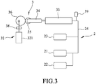
- the vehicle 2 includes a left shock-absorbing device 21 coupled with a left front wheel, a right shock-absorbing device 22 coupled with a right front wheel, a tiltable mechanism 23 pivotally connected to a front vehicle frame and coupled between the left and right shock-absorbing devices 21, 22, and a hydraulic fluid circuit 24 connected to the left and right shock-absorbing devices 21, 22 and the tiltable mechanism 23.
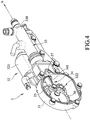
- the hydraulic control device 3 is employed for connecting with the hydraulic fluid circuit 24, and includes a housing 31, an actuator 32, a main pump 33 disposed on the housing 31 and having a cylinder body 330 which defines and is elongated along an axial line (A) that extends in an axial direction, an actuating lever 34 having an end which is connected with the main pump 33 and extending along the axial line (A), a thrust member 35 pivotably mounted on an opposite end of the actuating lever 34 about a thrust rotation center 351, a cam 36 pivotably mounted on the housing 31 about a cam rotation center 361 that is located at the axial line (A) and in sliding contact with the thrust member 35, a cam angle sensor 38 for detecting the cam 36, and a pressure sensor 39 for detecting the hydraulic fluid circuit 24.
- the actuator 32 includes a motor 321 disposed on the housing 31, and a reduction gearing assembly 322 disposed in the housing 31 and coupled with the motor 321 and the cam 36 to transmit a driving force of the motor 321 so as to rotate the cam 36 at a reduced speed.
- the main pump 33 is mechanically actuated to create a fluid pressure or provide a pressurized hydraulic fluid to the hydraulic fluid circuit 24 so as to control the left and right shock-absorbing devices 21, 22 and the tiltable mechanism 23.
- the actuating lever 34 is movably mounted in the housing 31, and has a guide groove 341 formed in an outer peripheral wall of the actuating lever 34 and elongated in the axial direction.
- the housing 31 has a guide pin 37 which extends in and is slidable along the guide groove 341 to guide a linear movement of the actuating lever 34 in the axial direction.
- the thrust member 35 is in the form of a roller which is circular in cross-section and is pivotably connected to the actuating lever 34 about a roller axis that is transverse to the axial direction for facilitating replacement and maintenance of the thrust member 35.
- the cam 36 is circular in cross-section, and has the cam rotation center 361 located at the axial line (A), and a center of circle which is distant from the cam rotation center 361 by a distance in the axial direction.
- the cam angle sensor 38 is disposed to detect the rotation angle of the cam 36 and electrically connected with the motor 321 to control a driving force of the motor 321.
- the pressure sensor 39 is disposed to detect a fluid pressure in the hydraulic fluid circuit 24 and electrically connected with the motor 321 to control a driving force of the motor 321.
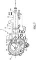
- the cam 36 and the reduction gearing assembly 322 are mounted on a spindle 323 which is rotatable relative to the housing 31 such that the spindle 323 is rotated when the reduction gearing assembly 322 is rotated by means of the motor 321 so as to allow the cam 36 to eccentrically rotate about the cam rotation center 361 to perform a reciprocation between an initial position (see FIG. 5 ) and a working position (see FIG. 7 ).
- the geometric center of the thrust member 35 coincides with the thrust rotation center 351 such that, in the initial position, the cam rotation center 361 of the cam 36 is distant from the thrust rotation center 351 of the thrust member 35 by a shortest distance, and, in the working position, the distance between the cam rotation center 361 and the thrust rotation center 351 is the largest.
- a contact (B) of the thrust member 35 with the cam 36 is brought gradually close to an extending line through the cam rotation center 361 and the thrust rotation center 351 once the contact (B) is away from the extending line.
- the extending line coincides with the axial line (A).
- the eccentric rotation of the cam 36 results in the linear movement of the thrust member 35 in the axial direction to transmit a working thrust to the actuating lever 34 for the same to perform a reciprocating movement along the axial line (A), which in turn actuates the main pump 33 to create a fluid pressure or provide a pressurized hydraulic fluid to the hydraulic fluid circuit 24 for locking or unlocking either one of the left and right shock-absorbing devices 21, 22 and the tiltable mechanism 23 (see FIG. 3 ).
- the profile of the cam 36 is determined in accordance with the required pressure stroke of the main pump 33 that is estimated by the required amount of fluid and pressure for a locking action. For instance, in this embodiment, when the cam 36 is in the initial position (i.e., an angular position of 0 degree), as shown in FIG. 5 , the moving distance of the thrust member 35 is the smallest so that the main pump 33 is in a fluid pressure releasing state or a pressurized hydraulic fluid unprovided state. When the cam 36 is in the working position (i.e. an angular position of about 120 degrees), as shown in FIG. 7 , the moving distance of the thrust member 35 is the largest so as to provide the main pump 33 with the largest amount of fluidpressure or pressurized hydraulic fluid.
- the axial line (A) extends through the rotation centers 351, 361 of the thrust member 35 and the cam 36.
- the thrust member 35 and the cam 36 are subjected to a reaction force which extends along an action line (C) that passes through the contact (B).
- FIG. 8 illustrates the contact (B) of the cam 36 with the thrust member 35 along with the incremental angle of rotation of the cam 36.
- the horizontal axis indicates the rotation angle (degrees) of the cam 36
- the vertical axis indicates the thrust output (kilograms) of the thrust member 35.
- the solid line (L1) may represent an internal thrust of the main pump 33 along with the incremental angle of rotation of the cam 36.
- the dashed line (L2) may represent an internal thrust of the main pump 33 along with the incremental angle of rotation of another cam 36, under the condition that such cam 36 has a profile with a varied cam surface.
- the threshold of the dashed line (L2) (at the nearly vertical segment of the dashed line (L2)) is larger than the threshold of the solid line (L1) (at the nearly vertical segment of the solid line (L1)).
- the square-marked solid line (L3) may represent the largest thrust that the thrust member 35 can apply upon the actuating lever 34, and is determined by the maximum rated torque of the motor 321.
- FIGS. 8 and 9 illustrate that varying the configuration of the cam 36 can increase a power output of the hydraulic control device 3 without the need to vary the motor 321.
- the cam 36 eccentrically rotated about the cam rotation center 361 to perform a reciprocation and to rotate the thrust member 35, the arm of force (E) of the reaction is shortened so as to reduce the torque (F) of the reaction, and in turn reduce the loading of the motor 321.
- the power output of the hydraulic control device 3 can be relatively high so as to facilitate miniaturization of the device 3.
- the thrust member 35 and the cam 36 have a simple construction that is easy to manufacture at a relatively low manufacturing cost.
- the cam 36 may be in a non-circular shape with various curvatures determined in accordance with the requirements.
- the guide pin 37 can guide the linear movement of the actuating lever 34 to prevent deflection of the thrust member 35.
- the thrust member 35 is integrally formed on the opposite end of the actuating lever 34, and has an arcuate surface 352 which has a constant radius of curvature in terms of a center of curvature 353.
- the cam 36 is configured to be in sliding contact with the arcuate surface 352 of the thrust member 35 when rotated, so as to transmit a working thrust to the actuating lever 34 along an axial direction .
- the cam 36 is rotated from an initial position, where the cam rotation center 361 is distant from the center of curvature 353 by a shortest distance, to a working position.
- a contact (B) of the thrust member 35 with the cam 36 is brought gradually close to an extending line through the cam rotation center 361 and the center of curvature 353 of the thrust member 35 once the contact (B) is away from the extending line.
- Such arrangement and structure of the thrust member 35 can enhance the structural strength of the thrust member 35, require a fewer number of components to thereby render manufacture easy and reduce the manufacturing cost, and broaden the workability of the device 3.
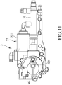
- the actuator 32 includes a motor 321 which is directly coupled with the cam 36 through the spindle 323 to rotate the cam 36 without any gearing construction so as to render the construction simple.
Landscapes
- Engineering & Computer Science (AREA)
- General Engineering & Computer Science (AREA)
- Mechanical Engineering (AREA)
- Transportation (AREA)
- Reciprocating Pumps (AREA)
- Transmission Devices (AREA)
- Fluid-Pressure Circuits (AREA)
Abstract
Description
- The disclosure relates to a hydraulic system for a vehicle, and more particularly to a hydraulic control device for a straddle type vehicle that provides a pressurized hydraulic fluid to a hydraulic fluid circuit and is to be directed to different subsystems.
- Referring to
FIGS. 1 and2 , a knownselective actuation device 1 for a vehicle disclosed inEP 1562098 includes anactuator 11 acting upon anactuation lever 14. Theactuation lever 14 has athruster element 141 for the actuation of a first operating group represented by anoil pump 16 which, in acting upon ahydraulic circuit 15, in turn activates alocking device 17 of an anti-rolling system andstroke stop devices 18, 18' of front suspensions. Acam element 19 is movable by theactuation lever 14 between an activation position in which thecam element 19 acts upon a second operating group represented by acable 20 to actuate a rear brake of the vehicle, and a rest position in which the activation of the first operating group is disassociated from the second operating group. In particular, theactuator 11, through a worm screw, acts upon an adaptedpinion 12, which makesgears - For use in a variety of vehicles having different engine displacements, it is sometimes necessary to increase a power output of the
actuation device 1 by increasing the power of a motor, hence increasing the ratio of an external reduction gear assembly, or increasing the lever ratio, for example. However, increment of the power of a motor results in increment of coil windings or increment of speed-reduction ratio, which upsizes the components of theactuation device 1. Increment of the ratio of the external reduction gear assembly renders the size of the structure large, and elongates the required operating time. Increment of the lever ratio causes the transmitting mechanism to have complex arrangement and be upsized. - Therefore, an object of the disclosure is to provide a hydraulic control device that can alleviate at least one of the drawbacks of the prior art.
- According to a first aspect of the disclosure, the hydraulic control device is for connecting with a hydraulic fluid circuit of a vehicle, and includes a housing, an actuator, a main pump mechanically actuated to create a fluid pressure or provide a pressurized hydraulic fluid to the hydraulic fluid circuit, an actuating lever having an end which is connected with the main pump, a thrust member rotatably mounted on an opposite end of the actuating lever about a thrust rotation center, and a cam rotatably mounted on the housing and actuated by the actuator to be rotated about a cam rotation center. The cam is configured to be in sliding contact with the thrust member to rotate the thrust member about the thrust rotation center when rotated, so as to transmit a working thrust to the actuating lever along an axial direction. The cam is rotatable from an initial position, where the cam rotation center is distant from the thrust rotation center by a shortest distance, to a working position. During the rotation from the initial position to the working position, when the cam is rotated toward an angular position, where a largest thrust is applied upon the actuating lever, a contact of the thrust member with the cam is brought gradually close to an extending line through the cam rotation center and the thrust rotation center once the contact is away from the extending line.
- According to a second aspect of the disclosure, the hydraulic control device is for connecting with a hydraulic fluid circuit of a vehicle, and includes a housing, an actuator, a main pump mechanically actuated to create a fluid pressure or provide a pressurized hydraulic fluid to the hydraulic fluid circuit, an actuating lever having an end which is connected with the main pump, a thrust member integrally formed on an opposite end of the actuating lever, and having an arcuate surface which has a constant radius of curvature in terms of a center of curvature, and a cam rotatably mounted on the housing and actuated by the actuator to be rotated about a cam rotation center. The cam is configured to be in sliding contact with the arcuate surface of the thrust member when rotated, to transmit a working thrust to the actuating lever along an axial direction. The cam is rotatable from an initial position, where the cam rotation center is distant from the center of curvature by a shortest distance, to a working position. During the rotation from the initial position to the working position, when the cam is rotated toward an angular position, where a largest thrust is applied upon the actuating lever, a contact of the thrust member with the cam is brought gradually close to an extending line through the cam rotation center and the center of curvature of the thrust member once the contact is away from the extending line.
- Other features and advantages of the disclosure will become apparent in the following detailed description of the embodiments with reference to the accompanying drawings, of which:
-
FIG. 1 is a perspective view of a conventional selective actuation device disclosed inEP 1562098 ; -
FIG. 2 is a schematic view of the conventional selective actuation device incorporated in a vehicle; -
FIG. 3 is a schematic view illustrating an embodiment of a hydraulic control device for a vehicle according to the disclosure; -
FIG. 4 is a perspective view of a first embodiment of the hydraulic control device; -
FIG. 5 is a schematic side view illustrating the first embodiment in an initial position; -
FIGS. 6 and7 are schematic side views illustrating the movement of the first embodiment to a working position; -
FIG. 8 is a schematic view illustrating the rotation of a cam and the movement of a thrust member; -
FIG. 9 is a diagram illustrating the rotation angle of the cam, the hydraulic reaction force of a main pump and the thrust output of the thrust member; -
FIG. 10 is a schematic side view illustrating a second embodiment of the hydraulic control device for a vehicle according to the disclosure; and -
FIG. 11 is a schematic side view illustrating a third embodiment of the hydraulic control device for a vehicle according to the disclosure. - Before the disclosure is described in greater detail, it should be noted that where considered appropriate, reference numerals or terminal portions of reference numerals have been repeated among the figures to indicate corresponding or analogous elements, which may optionally have similar characteristics.
- Referring to
FIGS. 3 to 5 , a first embodiment of ahydraulic control device 3 is employed in avehicle 2. Thevehicle 2 includes a left shock-absorbingdevice 21 coupled with a left front wheel, a right shock-absorbingdevice 22 coupled with a right front wheel, atiltable mechanism 23 pivotally connected to a front vehicle frame and coupled between the left and right shock-absorbingdevices hydraulic fluid circuit 24 connected to the left and right shock-absorbingdevices tiltable mechanism 23. Thehydraulic control device 3 is employed for connecting with thehydraulic fluid circuit 24, and includes ahousing 31, anactuator 32, amain pump 33 disposed on thehousing 31 and having acylinder body 330 which defines and is elongated along an axial line (A) that extends in an axial direction, anactuating lever 34 having an end which is connected with themain pump 33 and extending along the axial line (A), athrust member 35 pivotably mounted on an opposite end of the actuatinglever 34 about athrust rotation center 351, acam 36 pivotably mounted on thehousing 31 about acam rotation center 361 that is located at the axial line (A) and in sliding contact with thethrust member 35, acam angle sensor 38 for detecting thecam 36, and apressure sensor 39 for detecting thehydraulic fluid circuit 24. - The
actuator 32 includes amotor 321 disposed on thehousing 31, and areduction gearing assembly 322 disposed in thehousing 31 and coupled with themotor 321 and thecam 36 to transmit a driving force of themotor 321 so as to rotate thecam 36 at a reduced speed. Themain pump 33 is mechanically actuated to create a fluid pressure or provide a pressurized hydraulic fluid to thehydraulic fluid circuit 24 so as to control the left and right shock-absorbingdevices tiltable mechanism 23. The actuatinglever 34 is movably mounted in thehousing 31, and has aguide groove 341 formed in an outer peripheral wall of the actuatinglever 34 and elongated in the axial direction. Thehousing 31 has aguide pin 37 which extends in and is slidable along theguide groove 341 to guide a linear movement of the actuatinglever 34 in the axial direction. In this embodiment, thethrust member 35 is in the form of a roller which is circular in cross-section and is pivotably connected to the actuatinglever 34 about a roller axis that is transverse to the axial direction for facilitating replacement and maintenance of thethrust member 35. Thecam 36 is circular in cross-section, and has thecam rotation center 361 located at the axial line (A), and a center of circle which is distant from thecam rotation center 361 by a distance in the axial direction. Thecam angle sensor 38 is disposed to detect the rotation angle of thecam 36 and electrically connected with themotor 321 to control a driving force of themotor 321. Thepressure sensor 39 is disposed to detect a fluid pressure in thehydraulic fluid circuit 24 and electrically connected with themotor 321 to control a driving force of themotor 321. - With reference to
FIGS. 5 to 7 , in this embodiment, thecam 36 and thereduction gearing assembly 322 are mounted on aspindle 323 which is rotatable relative to thehousing 31 such that thespindle 323 is rotated when thereduction gearing assembly 322 is rotated by means of themotor 321 so as to allow thecam 36 to eccentrically rotate about thecam rotation center 361 to perform a reciprocation between an initial position (seeFIG. 5 ) and a working position (seeFIG. 7 ). In this embodiment, the geometric center of thethrust member 35 coincides with thethrust rotation center 351 such that, in the initial position, thecam rotation center 361 of thecam 36 is distant from thethrust rotation center 351 of thethrust member 35 by a shortest distance, and, in the working position, the distance between thecam rotation center 361 and thethrust rotation center 351 is the largest. During the rotation from the initial position to the working position, when thecam 36 is rotated toward an angular position, where a largest thrust is applied upon the actuating lever 34 (as shown inFIG. 9 , particularly the region of the solid line (L1) from the end of the nearly horizontal segment to the peak of the nearly vertical segment), a contact (B) of thethrust member 35 with thecam 36 is brought gradually close to an extending line through thecam rotation center 361 and thethrust rotation center 351 once the contact (B) is away from the extending line. In this embodiment, the extending line coincides with the axial line (A). The eccentric rotation of thecam 36 results in the linear movement of thethrust member 35 in the axial direction to transmit a working thrust to the actuatinglever 34 for the same to perform a reciprocating movement along the axial line (A), which in turn actuates themain pump 33 to create a fluid pressure or provide a pressurized hydraulic fluid to thehydraulic fluid circuit 24 for locking or unlocking either one of the left and right shock-absorbingdevices FIG. 3 ). - The profile of the
cam 36 is determined in accordance with the required pressure stroke of themain pump 33 that is estimated by the required amount of fluid and pressure for a locking action. For instance, in this embodiment, when thecam 36 is in the initial position (i.e., an angular position of 0 degree), as shown inFIG. 5 , the moving distance of thethrust member 35 is the smallest so that themain pump 33 is in a fluid pressure releasing state or a pressurized hydraulic fluid unprovided state. When thecam 36 is in the working position (i.e. an angular position of about 120 degrees), as shown inFIG. 7 , the moving distance of thethrust member 35 is the largest so as to provide themain pump 33 with the largest amount of fluidpressure or pressurized hydraulic fluid. - With reference to
FIGS. 4 ,8 and9 , the axial line (A) extends through therotation centers thrust member 35 and thecam 36. Thethrust member 35 and thecam 36 are subjected to a reaction force which extends along an action line (C) that passes through the contact (B). During the rotation of thecam 36, when thecam 36 is rotated toward the angular position, where a largest thrust is applied upon the actuatinglever 34, the contact (B) away from the axial line (A) is brought gradually close to the axial line (A) such that the included angle (D) between the axial line (A) and the action line (C) is gradually reduced, which shortens the arm of force (E) between the action line (C) and the axial line (A) so as to reduce the torque (F) generated as a result of the reaction, and in turn reduce the loading of themotor 321.FIG. 8 illustrates the contact (B) of thecam 36 with thethrust member 35 along with the incremental angle of rotation of thecam 36. InFIG. 9 , the horizontal axis indicates the rotation angle (degrees) of thecam 36, and the vertical axis indicates the thrust output (kilograms) of thethrust member 35. The solid line (L1) may represent an internal thrust of themain pump 33 along with the incremental angle of rotation of thecam 36. The dashed line (L2) may represent an internal thrust of themain pump 33 along with the incremental angle of rotation of anothercam 36, under the condition thatsuch cam 36 has a profile with a varied cam surface. The threshold of the dashed line (L2) (at the nearly vertical segment of the dashed line (L2)) is larger than the threshold of the solid line (L1) (at the nearly vertical segment of the solid line (L1)). The square-marked solid line (L3) may represent the largest thrust that thethrust member 35 can apply upon the actuatinglever 34, and is determined by the maximum rated torque of themotor 321.FIGS. 8 and9 illustrate that varying the configuration of thecam 36 can increase a power output of thehydraulic control device 3 without the need to vary themotor 321. - Through the
cam 36 eccentrically rotated about thecam rotation center 361 to perform a reciprocation and to rotate thethrust member 35, the arm of force (E) of the reaction is shortened so as to reduce the torque (F) of the reaction, and in turn reduce the loading of themotor 321. Thus, the power output of thehydraulic control device 3 can be relatively high so as to facilitate miniaturization of thedevice 3. Moreover, thethrust member 35 and thecam 36 have a simple construction that is easy to manufacture at a relatively low manufacturing cost. Thecam 36 may be in a non-circular shape with various curvatures determined in accordance with the requirements. Theguide pin 37 can guide the linear movement of the actuatinglever 34 to prevent deflection of thethrust member 35. - Referring to
FIG. 10 , in a second embodiment, thethrust member 35 is integrally formed on the opposite end of the actuatinglever 34, and has anarcuate surface 352 which has a constant radius of curvature in terms of a center ofcurvature 353. Thecam 36 is configured to be in sliding contact with thearcuate surface 352 of thethrust member 35 when rotated, so as to transmit a working thrust to theactuating lever 34 along an axial direction . Thecam 36 is rotated from an initial position, where thecam rotation center 361 is distant from the center ofcurvature 353 by a shortest distance, to a working position. During the rotation from the initial position to the working position, a contact (B) of thethrust member 35 with thecam 36 is brought gradually close to an extending line through thecam rotation center 361 and the center ofcurvature 353 of thethrust member 35 once the contact (B) is away from the extending line. Such arrangement and structure of thethrust member 35 can enhance the structural strength of thethrust member 35, require a fewer number of components to thereby render manufacture easy and reduce the manufacturing cost, and broaden the workability of thedevice 3. - Referring to
FIG. 11 , in a third embodiment, theactuator 32 includes amotor 321 which is directly coupled with thecam 36 through thespindle 323 to rotate thecam 36 without any gearing construction so as to render the construction simple.
Claims (14)
- A hydraulic control device (3) for connecting with a hydraulic fluid circuit (24) of a vehicle (2), comprising:a housing (31);an actuator (32);a main pump (33) mechanically actuated to create a fluid pressure or provide a pressurized hydraulic fluid to the hydraulic fluid circuit (24); andan actuating lever (34) having an end which is connected with said main pump (33), said hydraulic control device (3) being characterized in that said hydraulic control device (3) further comprises:a thrust member (35) rotatably mounted on an opposite end of said actuating lever (34) about a thrust rotation center (351); anda cam (36) rotatably mounted on said housing (31) and actuated by said actuator (32) to be rotated about a cam rotation center (361), said cam (36) being configured to be in sliding contact with said thrust member (35) to rotate said thrust member (35) about the thrust rotation center (351) when rotated, so as to transmit a working thrust to said actuating lever (34) along an axial direction, said cam (36) being rotatable from an initial position, where the cam rotation center (361) is distant from the thrust rotation center (351) by a shortest distance, to a working position, during the rotation from the initial position to the working position, when said cam (36) is rotated toward an angular position, where a largest thrust is applied upon said actuating lever (34), a contact (B) of said thrust member (35) with said cam (36) being brought gradually close to an extending line through the cam rotation center (361) and the thrust rotation center (351) once the contact (B) is away from the extending line.
- The hydraulic control device (3) as claimed in Claim 1, characterized in that said main pump (33) includes a cylinder body (330) which defines and is elongated along an axial line (A) that extends in the axial direction, said actuating lever (34) extending and being movable along the axial line (A), the extending line coinciding with the axial line (A) such that the cam rotation center (361) and the thrust rotation center (351) are located at the axial line (A).
- The hydraulic control device (3) as claimed in Claim 1, characterized in that said thrust member (35) is in the form of a roller which is pivotably connected to said actuating lever (34) about a roller axis that is transverse to the axial direction.
- The hydraulic control device (3) as claimed in Claim 1, characterized in that said actuator (32) includes a motor (321) and a reduction gearing assembly (322) coupled with said motor (321) and said cam (36) to transmit a driving force of said motor (321) to rotate said cam (36) at a reduced speed.
- The hydraulic control device (3) as claimed in Claim 1, characterized in that said actuator (32) includes a motor (321) coupled with said cam (36) to rotate said cam (36).
- The hydraulic control device (3) as claimed in Claim 4 or Claim 5, further characterized by a cam angle sensor (38) disposed to detect the rotation angle of said cam (36) and electrically connected with said motor (321) to control a driving force of said motor (321), and a pressure sensor (39) disposed to detect a fluid pressure in the hydraulic fluid circuit (24) and electrically connected with said motor (321) to control the driving force of said motor (321).
- The hydraulic control device (3) as claimed in Claim 1, characterized in that said actuating lever (34) is movably mounted in said housing (31), and has a guide groove (341) formed in an outer peripheral wall of said actuating lever (34) and elongated in the axial direction, said housing (31) having a guide pin (37) which extends in and is slidable along said guide groove (341) to guide a linear movement of said actuating lever (34) in the axial direction.
- The hydraulic control device (3) as claimed in Claim 1, characterized in that said cam (36) is circular in cross-section, and has a center of circle which is distant from the cam rotation center (361) by a distance in the axial direction.
- A hydraulic control device (3) for connecting with a hydraulic fluid circuit (24) of a vehicle (2), comprising:a housing (31);an actuator (32);a main pump (33) mechanically actuated to create a fluid pressure or provide a pressurized hydraulic fluid to the hydraulic fluid circuit (24); andan actuating lever (34) having an end which is connected with said main pump (33), said hydraulic control device (3) being characterized in that said hydraulic control device (3) further comprises:a thrust member (35) integrally formed on an opposite end of said actuating lever (34), and having an arcuate surface (352) which has a constant radius of curvature in terms of a center of curvature (353) ; anda cam (36) rotatably mounted on said housing (31) and actuated by said actuator (32) to be rotated about a cam rotation center (361), said cam (36) being configured to be in sliding contact with said arcuate surface (352) of said thrust member (35) when rotated, to transmit a working thrust to said actuating lever (34) along an axial direction, said cam (36) being rotatable from an initial position, where the cam rotation center (361) is distant from the center of curvature (353) by a shortest distance, to a working position, during the rotation from the initial position to the working position, when said cam (36) is rotated toward an angular position, where a largest thrust is applied upon said actuating lever (34), a contact (B) of said thrust member (35) with said cam (36) being brought gradually close to an extending line through the cam rotation center (361) and the center of curvature (353) of said thrust member (35) once the contact (B) is away from the extending line.
- The hydraulic control device (3) as claimed in Claim 9, characterized in that said actuator (32) includes a motor (321) and a reduction gearing assembly (322) coupled with said motor (321) and said cam (36) to transmit a driving force of said motor (321) to rotate said cam (36) at a reduced speed.
- The hydraulic control device (3) as claimed in Claim 9, characterized in that said actuator (32) includes a motor (321) coupled with said cam (36) to rotate said cam (36).
- The hydraulic control device (3) as claimed in Claim 10 or Claim 11, further characterized by a cam angle sensor (38) disposed to detect the rotation angle of said cam (36) and electrically connected with said motor (321) to control a driving force of said motor (321), and a pressure sensor (39) disposed to detect a fluid pressure in the hydraulic fluid circuit (24) and electrically connected with said motor (321) to control the driving force of said motor (321).
- The hydraulic control device (3) as claimed in Claim 9, characterized in that said actuating lever (34) is movably mounted in said housing (31), and has a guide groove (341) formed in an outer peripheral wall of said actuating lever (34) and elongated in the axial direction, said housing (31) having a guide pin (37) which extends in and is slidable along said guide groove (341) to guide a linear movement of said actuating lever (34) in the axial direction.
- The hydraulic control device (3) as claimed in Claim 9, characterized in that said cam (36) is circular in cross-section, and has a center of circle which is distant from the cam rotation center (361) by a distance in the axial direction.
Applications Claiming Priority (1)
| Application Number | Priority Date | Filing Date | Title |
|---|---|---|---|
| TW106138551A TWI644819B (en) | 2017-11-08 | 2017-11-08 | Hydraulic drive unit for vehicles |
Publications (2)
| Publication Number | Publication Date |
|---|---|
| EP3483480A1 true EP3483480A1 (en) | 2019-05-15 |
| EP3483480B1 EP3483480B1 (en) | 2020-11-25 |
Family
ID=65431808
Family Applications (1)
| Application Number | Title | Priority Date | Filing Date |
|---|---|---|---|
| EP18204898.3A Active EP3483480B1 (en) | 2017-11-08 | 2018-11-07 | Hydraulic control device for a vehicle |
Country Status (3)
| Country | Link |
|---|---|
| EP (1) | EP3483480B1 (en) |
| ES (1) | ES2845550T3 (en) |
| TW (1) | TWI644819B (en) |
Cited By (2)
| Publication number | Priority date | Publication date | Assignee | Title |
|---|---|---|---|---|
| US20220297659A1 (en) * | 2019-08-16 | 2022-09-22 | Zf Cv Systems Europe Bv | Electromechanical brake actuator and cam disc |
| US20240287967A1 (en) * | 2021-06-30 | 2024-08-29 | Vestas Wind Systems A/S | A segmented wind turbine tower section and method of assembling same |
Families Citing this family (1)
| Publication number | Priority date | Publication date | Assignee | Title |
|---|---|---|---|---|
| TWI774094B (en) * | 2020-10-22 | 2022-08-11 | 光陽工業股份有限公司 | Tiltable vehicle with two front wheels |
Citations (5)
| Publication number | Priority date | Publication date | Assignee | Title |
|---|---|---|---|---|
| US4913624A (en) * | 1987-08-11 | 1990-04-03 | Hitachi, Ltd. | Low pulsation displacement pump |
| US5868555A (en) * | 1995-11-13 | 1999-02-09 | Nisshinbo Industries, Inc. | Hydraulic drive unit of a press machine and a swash plate type variable capacity axial piston pump to use for said device |
| US6446435B1 (en) * | 1998-06-05 | 2002-09-10 | Robert Bosch Gmbh | Hydraulic braking system for automobiles |
| EP1562098A1 (en) | 2004-02-04 | 2005-08-10 | PIAGGIO & C. S.p.A. | Selective actuation device |
| WO2013098119A1 (en) * | 2011-12-30 | 2013-07-04 | Continental Automotive Gmbh | High pressure pump and system |
Family Cites Families (4)
| Publication number | Priority date | Publication date | Assignee | Title |
|---|---|---|---|---|
| GB8818912D0 (en) * | 1988-08-09 | 1988-09-14 | Lucas Ind Plc | Hydraulic pump & motor assemblies for vehicle hydraulic systems |
| JP4736532B2 (en) * | 2005-05-17 | 2011-07-27 | トヨタ自動車株式会社 | Hydraulic control device |
| TWI356782B (en) * | 2009-05-12 | 2012-01-21 | Sanyang Industry Co Ltd | Hydraulic brake system |
| JP5880402B2 (en) * | 2012-11-15 | 2016-03-09 | 株式会社アドヴィックス | Brake hydraulic pressure control device |
-
2017
- 2017-11-08 TW TW106138551A patent/TWI644819B/en active
-
2018
- 2018-11-07 ES ES18204898T patent/ES2845550T3/en active Active
- 2018-11-07 EP EP18204898.3A patent/EP3483480B1/en active Active
Patent Citations (5)
| Publication number | Priority date | Publication date | Assignee | Title |
|---|---|---|---|---|
| US4913624A (en) * | 1987-08-11 | 1990-04-03 | Hitachi, Ltd. | Low pulsation displacement pump |
| US5868555A (en) * | 1995-11-13 | 1999-02-09 | Nisshinbo Industries, Inc. | Hydraulic drive unit of a press machine and a swash plate type variable capacity axial piston pump to use for said device |
| US6446435B1 (en) * | 1998-06-05 | 2002-09-10 | Robert Bosch Gmbh | Hydraulic braking system for automobiles |
| EP1562098A1 (en) | 2004-02-04 | 2005-08-10 | PIAGGIO & C. S.p.A. | Selective actuation device |
| WO2013098119A1 (en) * | 2011-12-30 | 2013-07-04 | Continental Automotive Gmbh | High pressure pump and system |
Cited By (3)
| Publication number | Priority date | Publication date | Assignee | Title |
|---|---|---|---|---|
| US20220297659A1 (en) * | 2019-08-16 | 2022-09-22 | Zf Cv Systems Europe Bv | Electromechanical brake actuator and cam disc |
| US12227154B2 (en) * | 2019-08-16 | 2025-02-18 | Zf Cv Systems Europe Bv | Electromechanical brake actuator and cam disc |
| US20240287967A1 (en) * | 2021-06-30 | 2024-08-29 | Vestas Wind Systems A/S | A segmented wind turbine tower section and method of assembling same |
Also Published As
| Publication number | Publication date |
|---|---|
| ES2845550T3 (en) | 2021-07-27 |
| EP3483480B1 (en) | 2020-11-25 |
| TWI644819B (en) | 2018-12-21 |
| TW201918405A (en) | 2019-05-16 |
Similar Documents
| Publication | Publication Date | Title |
|---|---|---|
| JP7002582B2 (en) | Electromechanical brake booster and brake system | |
| EP3483480B1 (en) | Hydraulic control device for a vehicle | |
| CN103661315B (en) | There is the electric caliper brake of parking function | |
| US10647350B2 (en) | Steering gear for a vehicle, vehicle, method for controlling a steering gear and method for steering a vehicle | |
| JP7089974B2 (en) | Steering device | |
| US11649881B2 (en) | Mechanical spring actuator | |
| CN110792741B (en) | Pivotable spindle nut | |
| JP5487902B2 (en) | Clutch actuator | |
| US20160215863A1 (en) | Cam gear and linear drive device comprising said cam gear | |
| CN112049179B (en) | Manually operable control device | |
| CN110775148A (en) | Steering device | |
| CN101844582B (en) | Rack-and-pinion steering gear with low cost | |
| KR102582455B1 (en) | Electronic disc brake | |
| US4784234A (en) | Motor driven power steering system | |
| JP2015135159A (en) | Electric actuator and vehicle brake system | |
| EP2636575A1 (en) | Steering system | |
| CN110741187A (en) | Parking lock for automatic transmission in motor vehicle | |
| US20200300275A1 (en) | Valve device | |
| CN102022457A (en) | Electro-hydraulic vehicle clutch automatic control mechanism | |
| DE10212879A1 (en) | Actuation mechanism for a parking brake | |
| EP4610144A1 (en) | Steering system for motor vehicle and motor vehicle comprising the same | |
| JPH08504148A (en) | Power steering device for automobile | |
| JPH06281513A (en) | Torque sensor | |
| CN218228963U (en) | Piston pump assembly of integrated electro-hydraulic brake system | |
| DE102011051529A1 (en) | Steering system for commercial vehicle, has electric drive motor for producing supporting drive torque, and mechanical acting unit e.g. counter element and stopper element, defining output shaft angle |
Legal Events
| Date | Code | Title | Description |
|---|---|---|---|
| PUAI | Public reference made under article 153(3) epc to a published international application that has entered the european phase |
Free format text: ORIGINAL CODE: 0009012 |
|
| STAA | Information on the status of an ep patent application or granted ep patent |
Free format text: STATUS: THE APPLICATION HAS BEEN PUBLISHED |
|
| AK | Designated contracting states |
Kind code of ref document: A1 Designated state(s): AL AT BE BG CH CY CZ DE DK EE ES FI FR GB GR HR HU IE IS IT LI LT LU LV MC MK MT NL NO PL PT RO RS SE SI SK SM TR |
|
| AX | Request for extension of the european patent |
Extension state: BA ME |
|
| STAA | Information on the status of an ep patent application or granted ep patent |
Free format text: STATUS: REQUEST FOR EXAMINATION WAS MADE |
|
| 17P | Request for examination filed |
Effective date: 20191111 |
|
| RBV | Designated contracting states (corrected) |
Designated state(s): AL AT BE BG CH CY CZ DE DK EE ES FI FR GB GR HR HU IE IS IT LI LT LU LV MC MK MT NL NO PL PT RO RS SE SI SK SM TR |
|
| STAA | Information on the status of an ep patent application or granted ep patent |
Free format text: STATUS: EXAMINATION IS IN PROGRESS |
|
| 17Q | First examination report despatched |
Effective date: 20200109 |
|
| RIC1 | Information provided on ipc code assigned before grant |
Ipc: F16H 61/00 20060101AFI20200409BHEP Ipc: F16D 65/28 20060101ALI20200409BHEP Ipc: B60T 13/74 20060101ALI20200409BHEP Ipc: B60G 21/00 20060101ALI20200409BHEP |
|
| GRAP | Despatch of communication of intention to grant a patent |
Free format text: ORIGINAL CODE: EPIDOSNIGR1 |
|
| STAA | Information on the status of an ep patent application or granted ep patent |
Free format text: STATUS: GRANT OF PATENT IS INTENDED |
|
| INTG | Intention to grant announced |
Effective date: 20200619 |
|
| GRAS | Grant fee paid |
Free format text: ORIGINAL CODE: EPIDOSNIGR3 |
|
| GRAA | (expected) grant |
Free format text: ORIGINAL CODE: 0009210 |
|
| STAA | Information on the status of an ep patent application or granted ep patent |
Free format text: STATUS: THE PATENT HAS BEEN GRANTED |
|
| AK | Designated contracting states |
Kind code of ref document: B1 Designated state(s): AL AT BE BG CH CY CZ DE DK EE ES FI FR GB GR HR HU IE IS IT LI LT LU LV MC MK MT NL NO PL PT RO RS SE SI SK SM TR |
|
| REG | Reference to a national code |
Ref country code: GB Ref legal event code: FG4D |
|
| REG | Reference to a national code |
Ref country code: CH Ref legal event code: EP |
|
| REG | Reference to a national code |
Ref country code: AT Ref legal event code: REF Ref document number: 1338714 Country of ref document: AT Kind code of ref document: T Effective date: 20201215 |
|
| REG | Reference to a national code |
Ref country code: DE Ref legal event code: R096 Ref document number: 602018010086 Country of ref document: DE |
|
| REG | Reference to a national code |
Ref country code: IE Ref legal event code: FG4D |
|
| REG | Reference to a national code |
Ref country code: AT Ref legal event code: MK05 Ref document number: 1338714 Country of ref document: AT Kind code of ref document: T Effective date: 20201125 |
|
| REG | Reference to a national code |
Ref country code: NL Ref legal event code: MP Effective date: 20201125 |
|
| PG25 | Lapsed in a contracting state [announced via postgrant information from national office to epo] |
Ref country code: PT Free format text: LAPSE BECAUSE OF FAILURE TO SUBMIT A TRANSLATION OF THE DESCRIPTION OR TO PAY THE FEE WITHIN THE PRESCRIBED TIME-LIMIT Effective date: 20210325 Ref country code: RS Free format text: LAPSE BECAUSE OF FAILURE TO SUBMIT A TRANSLATION OF THE DESCRIPTION OR TO PAY THE FEE WITHIN THE PRESCRIBED TIME-LIMIT Effective date: 20201125 Ref country code: FI Free format text: LAPSE BECAUSE OF FAILURE TO SUBMIT A TRANSLATION OF THE DESCRIPTION OR TO PAY THE FEE WITHIN THE PRESCRIBED TIME-LIMIT Effective date: 20201125 Ref country code: GR Free format text: LAPSE BECAUSE OF FAILURE TO SUBMIT A TRANSLATION OF THE DESCRIPTION OR TO PAY THE FEE WITHIN THE PRESCRIBED TIME-LIMIT Effective date: 20210226 Ref country code: NO Free format text: LAPSE BECAUSE OF FAILURE TO SUBMIT A TRANSLATION OF THE DESCRIPTION OR TO PAY THE FEE WITHIN THE PRESCRIBED TIME-LIMIT Effective date: 20210225 |
|
| PG25 | Lapsed in a contracting state [announced via postgrant information from national office to epo] |
Ref country code: SE Free format text: LAPSE BECAUSE OF FAILURE TO SUBMIT A TRANSLATION OF THE DESCRIPTION OR TO PAY THE FEE WITHIN THE PRESCRIBED TIME-LIMIT Effective date: 20201125 Ref country code: IS Free format text: LAPSE BECAUSE OF FAILURE TO SUBMIT A TRANSLATION OF THE DESCRIPTION OR TO PAY THE FEE WITHIN THE PRESCRIBED TIME-LIMIT Effective date: 20210325 Ref country code: PL Free format text: LAPSE BECAUSE OF FAILURE TO SUBMIT A TRANSLATION OF THE DESCRIPTION OR TO PAY THE FEE WITHIN THE PRESCRIBED TIME-LIMIT Effective date: 20201125 Ref country code: LV Free format text: LAPSE BECAUSE OF FAILURE TO SUBMIT A TRANSLATION OF THE DESCRIPTION OR TO PAY THE FEE WITHIN THE PRESCRIBED TIME-LIMIT Effective date: 20201125 Ref country code: BG Free format text: LAPSE BECAUSE OF FAILURE TO SUBMIT A TRANSLATION OF THE DESCRIPTION OR TO PAY THE FEE WITHIN THE PRESCRIBED TIME-LIMIT Effective date: 20210225 Ref country code: AT Free format text: LAPSE BECAUSE OF FAILURE TO SUBMIT A TRANSLATION OF THE DESCRIPTION OR TO PAY THE FEE WITHIN THE PRESCRIBED TIME-LIMIT Effective date: 20201125 |
|
| REG | Reference to a national code |
Ref country code: LT Ref legal event code: MG9D |
|
| PG25 | Lapsed in a contracting state [announced via postgrant information from national office to epo] |
Ref country code: HR Free format text: LAPSE BECAUSE OF FAILURE TO SUBMIT A TRANSLATION OF THE DESCRIPTION OR TO PAY THE FEE WITHIN THE PRESCRIBED TIME-LIMIT Effective date: 20201125 |
|
| REG | Reference to a national code |
Ref country code: ES Ref legal event code: FG2A Ref document number: 2845550 Country of ref document: ES Kind code of ref document: T3 Effective date: 20210727 |
|
| PG25 | Lapsed in a contracting state [announced via postgrant information from national office to epo] |
Ref country code: SK Free format text: LAPSE BECAUSE OF FAILURE TO SUBMIT A TRANSLATION OF THE DESCRIPTION OR TO PAY THE FEE WITHIN THE PRESCRIBED TIME-LIMIT Effective date: 20201125 Ref country code: SM Free format text: LAPSE BECAUSE OF FAILURE TO SUBMIT A TRANSLATION OF THE DESCRIPTION OR TO PAY THE FEE WITHIN THE PRESCRIBED TIME-LIMIT Effective date: 20201125 Ref country code: CZ Free format text: LAPSE BECAUSE OF FAILURE TO SUBMIT A TRANSLATION OF THE DESCRIPTION OR TO PAY THE FEE WITHIN THE PRESCRIBED TIME-LIMIT Effective date: 20201125 Ref country code: EE Free format text: LAPSE BECAUSE OF FAILURE TO SUBMIT A TRANSLATION OF THE DESCRIPTION OR TO PAY THE FEE WITHIN THE PRESCRIBED TIME-LIMIT Effective date: 20201125 Ref country code: RO Free format text: LAPSE BECAUSE OF FAILURE TO SUBMIT A TRANSLATION OF THE DESCRIPTION OR TO PAY THE FEE WITHIN THE PRESCRIBED TIME-LIMIT Effective date: 20201125 Ref country code: LT Free format text: LAPSE BECAUSE OF FAILURE TO SUBMIT A TRANSLATION OF THE DESCRIPTION OR TO PAY THE FEE WITHIN THE PRESCRIBED TIME-LIMIT Effective date: 20201125 |
|
| REG | Reference to a national code |
Ref country code: DE Ref legal event code: R097 Ref document number: 602018010086 Country of ref document: DE |
|
| PG25 | Lapsed in a contracting state [announced via postgrant information from national office to epo] |
Ref country code: DK Free format text: LAPSE BECAUSE OF FAILURE TO SUBMIT A TRANSLATION OF THE DESCRIPTION OR TO PAY THE FEE WITHIN THE PRESCRIBED TIME-LIMIT Effective date: 20201125 |
|
| PLBE | No opposition filed within time limit |
Free format text: ORIGINAL CODE: 0009261 |
|
| STAA | Information on the status of an ep patent application or granted ep patent |
Free format text: STATUS: NO OPPOSITION FILED WITHIN TIME LIMIT |
|
| PG25 | Lapsed in a contracting state [announced via postgrant information from national office to epo] |
Ref country code: NL Free format text: LAPSE BECAUSE OF FAILURE TO SUBMIT A TRANSLATION OF THE DESCRIPTION OR TO PAY THE FEE WITHIN THE PRESCRIBED TIME-LIMIT Effective date: 20201125 Ref country code: AL Free format text: LAPSE BECAUSE OF FAILURE TO SUBMIT A TRANSLATION OF THE DESCRIPTION OR TO PAY THE FEE WITHIN THE PRESCRIBED TIME-LIMIT Effective date: 20201125 |
|
| 26N | No opposition filed |
Effective date: 20210826 |
|
| PG25 | Lapsed in a contracting state [announced via postgrant information from national office to epo] |
Ref country code: SI Free format text: LAPSE BECAUSE OF FAILURE TO SUBMIT A TRANSLATION OF THE DESCRIPTION OR TO PAY THE FEE WITHIN THE PRESCRIBED TIME-LIMIT Effective date: 20201125 |
|
| PG25 | Lapsed in a contracting state [announced via postgrant information from national office to epo] |
Ref country code: IS Free format text: LAPSE BECAUSE OF FAILURE TO SUBMIT A TRANSLATION OF THE DESCRIPTION OR TO PAY THE FEE WITHIN THE PRESCRIBED TIME-LIMIT Effective date: 20210325 |
|
| PG25 | Lapsed in a contracting state [announced via postgrant information from national office to epo] |
Ref country code: MC Free format text: LAPSE BECAUSE OF FAILURE TO SUBMIT A TRANSLATION OF THE DESCRIPTION OR TO PAY THE FEE WITHIN THE PRESCRIBED TIME-LIMIT Effective date: 20201125 |
|
| REG | Reference to a national code |
Ref country code: CH Ref legal event code: PL |
|
| PG25 | Lapsed in a contracting state [announced via postgrant information from national office to epo] |
Ref country code: LU Free format text: LAPSE BECAUSE OF NON-PAYMENT OF DUE FEES Effective date: 20211107 Ref country code: BE Free format text: LAPSE BECAUSE OF NON-PAYMENT OF DUE FEES Effective date: 20211130 |
|
| REG | Reference to a national code |
Ref country code: BE Ref legal event code: MM Effective date: 20211130 |
|
| PG25 | Lapsed in a contracting state [announced via postgrant information from national office to epo] |
Ref country code: IE Free format text: LAPSE BECAUSE OF NON-PAYMENT OF DUE FEES Effective date: 20211107 |
|
| PG25 | Lapsed in a contracting state [announced via postgrant information from national office to epo] |
Ref country code: CY Free format text: LAPSE BECAUSE OF FAILURE TO SUBMIT A TRANSLATION OF THE DESCRIPTION OR TO PAY THE FEE WITHIN THE PRESCRIBED TIME-LIMIT Effective date: 20201125 |
|
| P01 | Opt-out of the competence of the unified patent court (upc) registered |
Effective date: 20230529 |
|
| GBPC | Gb: european patent ceased through non-payment of renewal fee |
Effective date: 20221107 |
|
| PG25 | Lapsed in a contracting state [announced via postgrant information from national office to epo] |
Ref country code: LI Free format text: LAPSE BECAUSE OF NON-PAYMENT OF DUE FEES Effective date: 20220701 Ref country code: HU Free format text: LAPSE BECAUSE OF FAILURE TO SUBMIT A TRANSLATION OF THE DESCRIPTION OR TO PAY THE FEE WITHIN THE PRESCRIBED TIME-LIMIT; INVALID AB INITIO Effective date: 20181107 Ref country code: CH Free format text: LAPSE BECAUSE OF NON-PAYMENT OF DUE FEES Effective date: 20220701 |
|
| PG25 | Lapsed in a contracting state [announced via postgrant information from national office to epo] |
Ref country code: GB Free format text: LAPSE BECAUSE OF NON-PAYMENT OF DUE FEES Effective date: 20221107 |
|
| REG | Reference to a national code |
Ref country code: DE Ref legal event code: R082 Ref document number: 602018010086 Country of ref document: DE Representative=s name: KANDLBINDER, MARKUS, DIPL.-PHYS., DE |
|
| PG25 | Lapsed in a contracting state [announced via postgrant information from national office to epo] |
Ref country code: MK Free format text: LAPSE BECAUSE OF FAILURE TO SUBMIT A TRANSLATION OF THE DESCRIPTION OR TO PAY THE FEE WITHIN THE PRESCRIBED TIME-LIMIT Effective date: 20201125 |
|
| PG25 | Lapsed in a contracting state [announced via postgrant information from national office to epo] |
Ref country code: TR Free format text: LAPSE BECAUSE OF FAILURE TO SUBMIT A TRANSLATION OF THE DESCRIPTION OR TO PAY THE FEE WITHIN THE PRESCRIBED TIME-LIMIT Effective date: 20201125 |
|
| PG25 | Lapsed in a contracting state [announced via postgrant information from national office to epo] |
Ref country code: MT Free format text: LAPSE BECAUSE OF FAILURE TO SUBMIT A TRANSLATION OF THE DESCRIPTION OR TO PAY THE FEE WITHIN THE PRESCRIBED TIME-LIMIT Effective date: 20201125 |
|
| PGFP | Annual fee paid to national office [announced via postgrant information from national office to epo] |
Ref country code: DE Payment date: 20251016 Year of fee payment: 8 |
|
| PGFP | Annual fee paid to national office [announced via postgrant information from national office to epo] |
Ref country code: IT Payment date: 20251124 Year of fee payment: 8 |
|
| PGFP | Annual fee paid to national office [announced via postgrant information from national office to epo] |
Ref country code: FR Payment date: 20251016 Year of fee payment: 8 |
|
| PGFP | Annual fee paid to national office [announced via postgrant information from national office to epo] |
Ref country code: ES Payment date: 20251209 Year of fee payment: 8 |