EP3483447A1 - Scroll compressor - Google Patents
Scroll compressor Download PDFInfo
- Publication number
- EP3483447A1 EP3483447A1 EP17824154.3A EP17824154A EP3483447A1 EP 3483447 A1 EP3483447 A1 EP 3483447A1 EP 17824154 A EP17824154 A EP 17824154A EP 3483447 A1 EP3483447 A1 EP 3483447A1
- Authority
- EP
- European Patent Office
- Prior art keywords
- wrap
- gap
- center
- end plate
- change
- Prior art date
- Legal status (The legal status is an assumption and is not a legal conclusion. Google has not performed a legal analysis and makes no representation as to the accuracy of the status listed.)
- Granted
Links
Images



Classifications
-
- F—MECHANICAL ENGINEERING; LIGHTING; HEATING; WEAPONS; BLASTING
- F04—POSITIVE - DISPLACEMENT MACHINES FOR LIQUIDS; PUMPS FOR LIQUIDS OR ELASTIC FLUIDS
- F04C—ROTARY-PISTON, OR OSCILLATING-PISTON, POSITIVE-DISPLACEMENT MACHINES FOR LIQUIDS; ROTARY-PISTON, OR OSCILLATING-PISTON, POSITIVE-DISPLACEMENT PUMPS
- F04C18/00—Rotary-piston pumps specially adapted for elastic fluids
- F04C18/02—Rotary-piston pumps specially adapted for elastic fluids of arcuate-engagement type, i.e. with circular translatory movement of co-operating members, each member having the same number of teeth or tooth-equivalents
- F04C18/0207—Rotary-piston pumps specially adapted for elastic fluids of arcuate-engagement type, i.e. with circular translatory movement of co-operating members, each member having the same number of teeth or tooth-equivalents both members having co-operating elements in spiral form
- F04C18/0246—Details concerning the involute wraps or their base, e.g. geometry
- F04C18/0269—Details concerning the involute wraps
- F04C18/0276—Different wall heights
-
- F—MECHANICAL ENGINEERING; LIGHTING; HEATING; WEAPONS; BLASTING
- F04—POSITIVE - DISPLACEMENT MACHINES FOR LIQUIDS; PUMPS FOR LIQUIDS OR ELASTIC FLUIDS
- F04C—ROTARY-PISTON, OR OSCILLATING-PISTON, POSITIVE-DISPLACEMENT MACHINES FOR LIQUIDS; ROTARY-PISTON, OR OSCILLATING-PISTON, POSITIVE-DISPLACEMENT PUMPS
- F04C18/00—Rotary-piston pumps specially adapted for elastic fluids
- F04C18/02—Rotary-piston pumps specially adapted for elastic fluids of arcuate-engagement type, i.e. with circular translatory movement of co-operating members, each member having the same number of teeth or tooth-equivalents
- F04C18/0207—Rotary-piston pumps specially adapted for elastic fluids of arcuate-engagement type, i.e. with circular translatory movement of co-operating members, each member having the same number of teeth or tooth-equivalents both members having co-operating elements in spiral form
- F04C18/0215—Rotary-piston pumps specially adapted for elastic fluids of arcuate-engagement type, i.e. with circular translatory movement of co-operating members, each member having the same number of teeth or tooth-equivalents both members having co-operating elements in spiral form where only one member is moving
-
- F—MECHANICAL ENGINEERING; LIGHTING; HEATING; WEAPONS; BLASTING
- F04—POSITIVE - DISPLACEMENT MACHINES FOR LIQUIDS; PUMPS FOR LIQUIDS OR ELASTIC FLUIDS
- F04C—ROTARY-PISTON, OR OSCILLATING-PISTON, POSITIVE-DISPLACEMENT MACHINES FOR LIQUIDS; ROTARY-PISTON, OR OSCILLATING-PISTON, POSITIVE-DISPLACEMENT PUMPS
- F04C23/00—Combinations of two or more pumps, each being of rotary-piston or oscillating-piston type, specially adapted for elastic fluids; Pumping installations specially adapted for elastic fluids; Multi-stage pumps specially adapted for elastic fluids
- F04C23/008—Hermetic pumps
-
- F—MECHANICAL ENGINEERING; LIGHTING; HEATING; WEAPONS; BLASTING
- F04—POSITIVE - DISPLACEMENT MACHINES FOR LIQUIDS; PUMPS FOR LIQUIDS OR ELASTIC FLUIDS
- F04C—ROTARY-PISTON, OR OSCILLATING-PISTON, POSITIVE-DISPLACEMENT MACHINES FOR LIQUIDS; ROTARY-PISTON, OR OSCILLATING-PISTON, POSITIVE-DISPLACEMENT PUMPS
- F04C18/00—Rotary-piston pumps specially adapted for elastic fluids
- F04C18/02—Rotary-piston pumps specially adapted for elastic fluids of arcuate-engagement type, i.e. with circular translatory movement of co-operating members, each member having the same number of teeth or tooth-equivalents
- F04C18/0207—Rotary-piston pumps specially adapted for elastic fluids of arcuate-engagement type, i.e. with circular translatory movement of co-operating members, each member having the same number of teeth or tooth-equivalents both members having co-operating elements in spiral form
- F04C18/0246—Details concerning the involute wraps or their base, e.g. geometry
- F04C18/0253—Details concerning the base
-
- F—MECHANICAL ENGINEERING; LIGHTING; HEATING; WEAPONS; BLASTING
- F04—POSITIVE - DISPLACEMENT MACHINES FOR LIQUIDS; PUMPS FOR LIQUIDS OR ELASTIC FLUIDS
- F04C—ROTARY-PISTON, OR OSCILLATING-PISTON, POSITIVE-DISPLACEMENT MACHINES FOR LIQUIDS; ROTARY-PISTON, OR OSCILLATING-PISTON, POSITIVE-DISPLACEMENT PUMPS
- F04C18/00—Rotary-piston pumps specially adapted for elastic fluids
- F04C18/02—Rotary-piston pumps specially adapted for elastic fluids of arcuate-engagement type, i.e. with circular translatory movement of co-operating members, each member having the same number of teeth or tooth-equivalents
- F04C18/0207—Rotary-piston pumps specially adapted for elastic fluids of arcuate-engagement type, i.e. with circular translatory movement of co-operating members, each member having the same number of teeth or tooth-equivalents both members having co-operating elements in spiral form
- F04C18/0246—Details concerning the involute wraps or their base, e.g. geometry
- F04C18/0269—Details concerning the involute wraps
-
- F—MECHANICAL ENGINEERING; LIGHTING; HEATING; WEAPONS; BLASTING
- F04—POSITIVE - DISPLACEMENT MACHINES FOR LIQUIDS; PUMPS FOR LIQUIDS OR ELASTIC FLUIDS
- F04C—ROTARY-PISTON, OR OSCILLATING-PISTON, POSITIVE-DISPLACEMENT MACHINES FOR LIQUIDS; ROTARY-PISTON, OR OSCILLATING-PISTON, POSITIVE-DISPLACEMENT PUMPS
- F04C2210/00—Fluid
- F04C2210/26—Refrigerants with particular properties, e.g. HFC-134a
- F04C2210/268—R32
-
- F—MECHANICAL ENGINEERING; LIGHTING; HEATING; WEAPONS; BLASTING
- F04—POSITIVE - DISPLACEMENT MACHINES FOR LIQUIDS; PUMPS FOR LIQUIDS OR ELASTIC FLUIDS
- F04C—ROTARY-PISTON, OR OSCILLATING-PISTON, POSITIVE-DISPLACEMENT MACHINES FOR LIQUIDS; ROTARY-PISTON, OR OSCILLATING-PISTON, POSITIVE-DISPLACEMENT PUMPS
- F04C2230/00—Manufacture
- F04C2230/60—Assembly methods
- F04C2230/602—Gap; Clearance
-
- F—MECHANICAL ENGINEERING; LIGHTING; HEATING; WEAPONS; BLASTING
- F04—POSITIVE - DISPLACEMENT MACHINES FOR LIQUIDS; PUMPS FOR LIQUIDS OR ELASTIC FLUIDS
- F04C—ROTARY-PISTON, OR OSCILLATING-PISTON, POSITIVE-DISPLACEMENT MACHINES FOR LIQUIDS; ROTARY-PISTON, OR OSCILLATING-PISTON, POSITIVE-DISPLACEMENT PUMPS
- F04C2240/00—Components
- F04C2240/30—Casings or housings
Definitions
- the present invention relates to a scroll compressor.
- a scroll compressor equipped with a fixed wrap and an orbiting wrap that have tooth bottom portions in which steps are formed so as to become deeper heading from an outer peripheral side to an inner peripheral side is known (see patent document 1 (International Publication No. WO 2014/155646 )).
- a scroll compressor pertaining to a first aspect of the invention has a fixed scroll and an orbiting scroll.
- the fixed scroll has a first base and a first wrap.
- the first wrap is formed spirally on the first base.
- the orbiting scroll forms a compression chamber together with the fixed scroll.
- the orbiting scroll has a second base and a second wrap.
- the second wrap is formed spirally on the second base.
- the scroll compressor satisfies at least one of a first condition and a second condition.
- the first condition is a condition where a first gap between a distal end of the first wrap and the second base changes heading from an outer peripheral side of the first wrap to an inner peripheral side and where the rate of change in the first gap from a center of the first wrap to an intermediate point of the first wrap is greater than the rate of change in the first gap from the intermediate point of the first wrap to an outer peripheral end of the first wrap.
- the second condition is a condition where a second gap between a distal end of the second wrap and the first base changes heading from an outer peripheral side of the second wrap to an inner peripheral side and where the rate of change in the second gap from a center of the second wrap to an intermediate point of the second wrap is greater than the rate of change in the second gap from the intermediate point of the second wrap to an outer peripheral end of the second wrap.
- the first gap from the center of the first wrap to the intermediate point of the first wrap becomes locally larger. Consequently, contact between the distal end of the first wrap and the second base can be inhibited at the portion of the first wrap from the center of the first wrap to the intermediate point of the first wrap.
- the second gap from the center of the second wrap to the intermediate point of the second wrap becomes locally larger. Consequently, contact between the distal end of the second wrap and the first base can be inhibited at the portion of the second wrap from the center of the second wrap to the intermediate point of the second wrap.
- the portion of the first wrap from the center of the first wrap to the intermediate point of the first wrap is a center portion of the first wrap
- the portion of the second wrap from the center of the second wrap to the intermediate point of the second wrap is a center portion of the second wrap
- the first gap at the center portion of the first wrap is set to become locally larger in anticipation of expansion of the first wrap due to heat at the center portion of the compression chamber, which can reach a particularly high temperature. Consequently, contact between the fixed scroll and the orbiting scroll at the center portion of the compression chamber can be inhibited.
- the second gap at the center portion of the second wrap is set to become locally larger in anticipation of expansion of the second wrap due to heat at the center portion of the compression chamber, which can reach a particularly high temperature. Consequently, contact between the fixed scroll and the orbiting scroll at the center portion of the compression chamber can be inhibited.
- the first gap changes in a stepwise manner heading from the outer peripheral side of the first wrap to the inner peripheral side.
- the second gap changes in a stepwise manner heading from the outer peripheral side of the second wrap to the inner peripheral side.
- the first gap and the second gap gradually change heading toward the center portion of the compression chamber, so contact between the fixed scroll and the orbiting scroll can be effectively inhibited.
- At least one of the first wrap and the second base is formed in a stepwise manner, whereby the first gap changes in a stepwise manner heading from the outer peripheral side of the first wrap to the inner peripheral side.
- At least one of the second wrap and the first base is formed in a stepwise manner, whereby the second gap changes in a stepwise manner heading from the outer peripheral side of the second wrap to the inner peripheral side.
- the at least one of the first wrap and the second base includes at least one step portion in the range of the center portion of the first wrap.
- the at least one of the second wrap and the first base includes at least one step portion in the range of the center portion of the second wrap.
- At least one of the first wrap and the second base is formed in a stepwise manner, so compared to a case where it is formed in a sloping manner, for example, processing for forming the first gap becomes easy.
- at least one of the second wrap and the first base is formed in a stepwise manner, so compared to a case where it is formed in a sloping manner, for example, processing for forming the second gap becomes easy.
- the first gap can easily be made locally larger.
- the second gap can easily be made locally larger.
- the center portion of the first wrap is a range from the center of the first wrap to 540°.
- the center portion of the second wrap is a range from the center of the second wrap to 540°.
- the first gap in the range from the center of the first wrap to 540° and the second gap in the range from the center of the second wrap to 540°, which can reach a particularly high temperature, become locally larger. Consequently, contact between the fixed scroll and the orbiting scroll can be effectively inhibited.
- the rate of change in the first gap from the center of the first wrap to the intermediate point of the first wrap is in the range of 4.5 times to 5.5 times the rate of change in the first gap from the intermediate point of the first wrap to the outer peripheral end of the first wrap.
- the rate of change in the second gap from the center of the second wrap to the intermediate point of the second wrap is in the range of 4.5 times to 5.5 times the rate of change in the second gap from the intermediate point of the second wrap to the outer peripheral end of the second wrap.
- the rate of change in the first gap from the center of the first wrap to the intermediate point of the first wrap is in the range of 4.5 times to 5.5 times the rate of change in the first gap from the intermediate point of the first wrap to the outer peripheral end of the first wrap
- the rate of change in the second gap from the center of the second wrap to the intermediate point of the second wrap is in the range of 4.5 times to 5.5 times the rate of change in the second gap from the intermediate point of the second wrap to the outer peripheral end of the second wrap
- the fixed scroll and the orbiting scroll compress refrigerant that includes more than 50 wt% R32 as refrigerant.
- the scroll compressor pertaining to the seventh aspect of the invention satisfies at least one of the first condition and the second condition, so contact between the fixed scroll and the orbiting scroll can be inhibited.
- processing for forming the first gap and the second gap becomes easy. Furthermore, the first gap at the center portion of the first wrap and the second gap at the center portion of the second wrap can easily be made locally larger.
- refrigerant that includes more than 50 wt% R32 is compressed, so even in a case where it becomes easier for the first wrap and the second wrap to deform, contact between the fixed scroll and the orbiting scroll can be inhibited.
- FIG. 1 is a longitudinal sectional view of a scroll compressor 101 pertaining to the embodiment.
- the scroll compressor 101 is used in a refrigerating system such as an air conditioning system.
- the scroll compressor 101 compresses refrigerant gas that circulates through a refrigerant circuit of the refrigerating system.
- refrigerant refrigerant that includes more than 50 wt% R32 can be used.
- the scroll compressor 101 mainly has a casing 10, a compression mechanism 15, a housing 23, an Oldham coupling 39, a drive motor 16, a lower bearing 60, a crankshaft 17, a suction pipe 19, and a discharge pipe 20.
- the casing 10 is configured from a middle casing portion 11 in the shape of an open cylinder, an upper wall portion 12 in the shape of a bowl, and a bottom wall portion 13 in the shape of a bowl.
- the upper wall portion 12 is airtightly welded to the upper end portion of the middle casing portion 11.
- the bottom wall portion 13 is airtightly welded to the lower end portion of the middle casing portion 11.
- the casing 10 is installed in such a way that the axial direction of the open cylinder shape of the middle casing portion 11 lies along the vertical direction.
- the compression mechanism 15 Inside the casing 10 are housed the compression mechanism 15, the housing 23, the drive motor 16, the crankshaft 17, and the like.
- an oil reservoir 10a In the bottom portion of the casing 10 is formed an oil reservoir 10a in which lubricating oil is stored. The lubricating oil is used to well maintain the lubricity of sliding portions of the compression mechanism 15 and the like during the operation of the scroll compressor 101.
- the compression mechanism 15 sucks and compresses low-temperature low-pressure refrigerant gas and discharges compressed refrigerant that is high-temperature high-pressure refrigerant gas.
- the compression mechanism 15 is configured mainly from a fixed scroll 24 and an orbiting scroll 26.
- the fixed scroll 24 is fixed with respect to the casing 10.
- the orbiting scroll 26 performs revolving movement with respect to the fixed scroll 24.
- the fixed scroll 24 has a first end plate 24a serving as a first base and a first wrap 24b.
- the first wrap 24b is formed upright on the first end plate 24a.
- the first wrap 24b is spiral in shape.
- the height of the first wrap 24b is preferably 20 to 40 mm.
- the number of turns of the first wrap 24b is longer than the number of turns of a later-described second wrap 26b. Specifically, it is about 1/2 turn longer.
- An outer peripheral surface is not formed on the outermost periphery of the first wrap 24b.
- the outermost periphery of the first wrap 24b is continuous with the edge portion of the fixed scroll 24.
- a main suction hole 24c is formed in the first end plate 24a.
- the main suction hole 24c is a space that interconnects the suction pipe 19 and a later-described compression chamber 40.
- the main suction hole 24c forms a suction space.
- the suction space is a space for introducing the low-temperature low-pressure refrigerant gas from the suction pipe 19 to the compression chamber 40.
- a discharge hole 41 is formed in the central portion of the first end plate 24a.
- An enlarged recess portion 42 that communicates with the discharge hole 41 is formed in the upper surface of the first end plate 24a.
- the enlarged recess portion 42 is a space that is recessedly provided in the upper surface of the first end plate 24a.
- a cover 44 is fixed by bolts 44a to the upper surface of the fixed scroll 24 so as to close off the enlarged recessed portion 42.
- the fixed scroll 24 and the cover 44 are tightly sealed via a gasket (not shown in the drawings).
- a muffler space 45 that muffles the operating sound of the compression mechanism 15 is formed as a result of the enlarged recessed portion 42 being covered with the cover 44.
- a first compressed refrigerant flow passage 46 that communicates with the muffler space 45 and opens to the lower surface of the fixed scroll 24 is formed in the fixed scroll 24.
- An oil groove 24e is formed in the lower surface of the first end plate 24a.
- the orbiting scroll 26 has a second end plate 26a serving as a second base and a second wrap 26b.
- the second end plate 26a is in the shape of a disc.
- An upper end bearing 26c is formed in the central portion of the lower surface of the second end plate 26a.
- the second wrap 26b is formed upright on the second end plate 26a.
- the second wrap 26b is spiral in shape.
- the height of the second wrap 26b is preferably 20 to 40 mm.
- An oil supply pore 63 is formed in the orbiting scroll 26. The oil supply pore 63 communicates the outer peripheral portion of the upper surface of the second end plate 26a to the space inside the upper end bearing 26c.
- the first wrap 24b and the second wrap 26b interfit, whereby the fixed scroll 24 and the orbiting scroll 26 form a compression chamber 40.
- the compression chamber 40 is a space enclosed by the first end plate 24a, the first wrap 24b, the second end plate 26a, and the second wrap 26b.
- the volume of the compression chamber 40 gradually decreases because of the revolving movement of the orbiting scroll 26.
- the orbiting scroll 26 revolves, the lower surface of the first end plate 24a and the first wrap 24b of the fixed scroll 24 slides against the upper surface of the second end plate 26a and the second wrap 26b of the orbiting scroll 26.
- the surface of the fixed scroll 24 that slides against the orbiting scroll 26 is called a sliding surface 24d.
- a first gap is formed between the distal end of the first wrap 24b (i.e., the portion of the first wrap 24b that opposes the second end plate 26a) and the second end plate 26a.
- a second gap is formed between the distal end of the second wrap 26b (i.e., the portion of the second wrap 26b that opposes the first end plate 24a) and the first end plate 24a.
- both a first condition and a second condition described below are satisfied in relation to the first gap and the second gap.
- the first condition is a condition where the first gap changes heading from the outer peripheral side of the first wrap 24b to the inner peripheral side and where the rate of change in the first gap in a range from a center 24p (see FIG. 2 ) of the first wrap 24b to an intermediate point of the first wrap 24b is greater than the rate of change in the first gap in a range from the intermediate point of the first wrap 24b to the outer peripheral end of the first wrap 24b.
- the range from the center 24p of the first wrap 24b to the intermediate point of the first wrap 24b is a range from the center 24p of the first wrap 24b to 540°.
- the range from the intermediate point of the first wrap 24b to the outer peripheral end of the first wrap 24b is a range from 540° of the first wrap 24b to 1080°.
- the rate of change in the first gap in the range from the center 24p of the first wrap 24b to 540° is a value obtained by dividing the amount of change in the height of the first gap in the range from the center 24p of the first wrap 24b to 540° by the number of steps included in the portion of the second end plate 26a corresponding to the range from the center 24p of the first wrap 24b to 540°.
- the rate of change in the first gap in the range from 540° of the first wrap 24b to 1080° is a value obtained by dividing the amount of change in the height of the first gap in the range from 540° of the first wrap 24b to 1080° by the number of steps included in the portion of the second end plate 26a corresponding to the range from 540° of the first wrap 24b to 1080°.
- the second condition is a condition where the second gap changes heading from the outer peripheral side of the second wrap 26b to the inner peripheral side and where the rate of change in the second gap in a range from a center 26p (see FIG. 3 ) of the second wrap 26b to an intermediate point of the second wrap 26b is greater than the rate of change in the second gap in a range from the intermediate point of the second wrap 26b to the outer peripheral end of the second wrap 26b.
- the range from the center 26p of the second wrap 26b to the intermediate point of the second wrap 26b is a range from the center 26p of the second wrap 24b to 540°.
- the range from the intermediate point of the second wrap 26b to the outer peripheral end of the second wrap 26b is a range from 540° to 900° of the second wrap 26b.
- the rate of change in the second gap in the range from the center 26p of the second wrap 26b to 540° is a value obtained by dividing the amount of change in the height of the second gap in the range from the center 26p of the second wrap 26b to 540° by the number of steps included in the portion of the first end plate 24a corresponding to the range from the center 26p of the second wrap 26b to 540°.
- the rate of change in the second gap in the range from 540° of the second wrap 26b to 900° is a value obtained by dividing the amount of change in the height of the second gap in the range from 540° of the second wrap 26b to 900° by the number of steps included in the portion of the first end plate 24a corresponding to the range from 540° of the second wrap 26b to 900°.
- the housing 23 is disposed under the compression mechanism 15.
- the outer peripheral surface of the housing 23 is airtightly joined to the inner peripheral surface of the middle casing portion 11. Because of this, the inside space of the casing 10 is partitioned into a high-pressure space S1 under the housing 23 and a low-pressure space S2 that is a space above the housing 23.
- the housing 23 has the fixed scroll 24 mounted on it and, together with the fixed scroll 24, sandwiches the orbiting scroll 26.
- a second compressed refrigerant flow passage 48 is formed in, so as to run in the vertical direction through, the outer peripheral portion of the housing 23.
- the second compressed refrigerant flow passage 48 communicates with the first compressed refrigerant flow passage 46 at the upper surface of the housing 23 and communicates with the high-pressure space S1 at the lower surface of the housing 23.
- a crank chamber S3 is recessedly provided in the upper surface of the housing 23.
- a housing through hole 31 is formed in the housing 23.
- the housing through hole 31 runs in the vertical direction through the housing 23 from the central portion of the bottom surface of the crank chamber S3 to the central portion of the lower surface of the housing 23.
- the part of the housing 23 that has the housing through hole 31 formed in it is called an upper bearing 32.
- an oil return passageway 23a that communicates the high-pressure space S1 in the neighborhood of the inner surface of the casing 10 to the crank chamber S3.
- the Oldham coupling 39 is an annular member installed between the orbiting scroll 26 and the housing 23.
- the Oldham coupling 39 is a member for preventing self-rotation of the revolving orbiting scroll 26.
- the drive motor 16 is a brushless DC motor disposed under the housing 23.
- the drive motor 16 is configured mainly from a stator 51 fixed to the inner surface of the casing 10 and a rotor 52 disposed inside the stator 51 with an air gap between them.
- stator 51 In the outer peripheral surface of the stator 51 are provided plural core cut portions comprising cutouts formed a predetermined interval apart from each other in the circumferential direction and ranging from the upper end surface of the stator 51 to the lower end surface.
- the core cut portions form motor cooling passageways 55 that extend in the vertical direction between the middle casing portion 11 and the stator 51.
- the rotor 52 is coupled to the crankshaft 17, which runs in the vertical direction through the rotational center of the rotor 52.
- the rotor 52 is connected via the crankshaft 17 to the compression mechanism 15.
- the lower bearing 60 is disposed under the drive motor 16.
- the outer peripheral surface of the lower bearing 60 is airtightly joined to the inner surface of the casing 10.
- the lower bearing 60 supports the crankshaft 17.
- the crankshaft 17 is disposed in such a way that its axial direction lies along the vertical direction.
- the crankshaft 17 has a shape in which the axial center of the upper end portion of the crankshaft 17 is slightly eccentric with respect to the axial center of the portion excluding the upper end portion.
- the crankshaft 17 has a counterweight 18.
- the counterweight 18 is tightly fixed to the crankshaft 17 at a height position under the housing 23 and above the drive motor 16.
- crankshaft 17 runs in the vertical direction through the rotational center of the rotor 52 and is coupled to the rotor 52.
- the upper end portion of the crankshaft 17 is fitted into the upper end bearing 26c, whereby the crankshaft 17 is connected to the orbiting scroll 26.
- the crankshaft 17 is supported by the upper bearing 32 and the lower bearing 60.
- the crankshaft 17 has inside a main oil supply passage 61 that extends in the axial direction of the crankshaft 17.
- the upper end of the main oil supply passage 61 communicates with an oil chamber 67 formed by the upper end surface of the crankshaft 17 and the lower surface of the second end plate 26a.
- the oil chamber 67 communicates with the sliding surface 24d and the oil groove 24e via the oil supply pore 63 in the second end plate 26a and finally communicates with the low-pressure space S2 via the compression chamber 40.
- the lower end of the main oil supply passage 61 is connected to an oil supply pipe that is a pipe for supplying to the compression mechanism 15 the lubricating oil stored in the oil reservoir 10a.
- the crankshaft 17 has a first auxiliary oil supply passage 61a, a second auxiliary oil supply passage 61b, and a third auxiliary oil supply passage 61c that branch from the main oil supply passage 61.
- the first auxiliary oil supply passage 61a, the second auxiliary oil supply passage 61b, and the third auxiliary oil supply passage 61c extend in the horizontal direction.
- the first auxiliary oil supply passage 61a opens to the sliding surfaces of the crankshaft 17 and the upper end bearing 26c of the orbiting scroll 26.
- the second auxiliary oil supply passage 61b opens to the sliding surfaces of the crankshaft 17 and the upper bearing 32 of the housing 23.
- the third auxiliary oil supply passage 61c opens to the sliding surfaces of the crankshaft 17 and the lower bearing 60.
- the suction pipe 19 is a pipe for introducing the refrigerant in the refrigerant circuit from the outside of the casing 10 to the compression mechanism 15.
- the suction pipe 19 is airtightly fitted into the upper wall portion 12 of the casing 10.
- the suction pipe 19 runs in the vertical direction through the low-pressure space S2.
- the discharge pipe 20 is a pipe for discharging the compressed refrigerant from the high-pressure space S1 to the outside of the casing 10.
- the discharge pipe 20 is airtightly fitted into the middle casing portion 11 of the casing 10.
- the discharge pipe 20 runs in the horizontal direction through the high-pressure space S1.
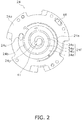
- FIG. 2 is a bottom view of the fixed scroll 24 seen along the vertical direction.
- Plural regions are formed in a refrigerant flow passage portion 24f of the fixed scroll 24 from the main suction hole 24c to the discharge hole 41.
- four regions are formed. Namely, a first region 34a, a second region 34b, a third region 34c, and a fourth region 34d are formed.
- the first region 34a is a region on the innermost peripheral side of the refrigerant flow passage portion 24f.
- the first region 34a is a region corresponding to a range from the center 24p of the first wrap 24b (i.e., the start of the spiral) to 540°.
- the range from the center 24p of the first wrap 24b to 540° is defined as the center portion of the first wrap 24b
- the first region 34a is defined as the center portion of the first end plate 24a.
- the center portions of the first wrap 24b and the first end plate 24a form a center portion of the compression chamber 40.
- the second region 34b is a region continuous with the first region 34a.
- the second region 34b is a region between the first region 34a and the third region 34c.
- the second region 34b is a region corresponding to a range from 540° of the first wrap 24b to 720°.
- the third region 34c is a region continuous with the second region 34b.
- the third region 34c is a region between the second region 34b and the fourth region 34d.
- the third region 34c is a region corresponding to a range from 720° of the first wrap 24b to 900°.
- the fourth region 34d is a region continuous with the third region 34c.
- the fourth region 34d is a region on the outermost peripheral side of the refrigerant flow passage portion 24f.
- the fourth region 34d is a region corresponding to a range from 900° of the first wrap 24b to the outer peripheral end (1080°).
- the range from 540° of the first wrap 24b to the outer peripheral end is defined as the non-center portion of the first wrap 24b, and the second region 34b, the third region 34c, and the fourth region 34d are defined as the non-center portion of the first end plate 24a.
- the non-center portions of the first wrap 24b and the first end plate 24a form a non-center portion of the compression chamber 40.
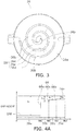
- FIG. 3 is a top view of the orbiting scroll 26 seen along the vertical direction.
- Plural regions are formed in a refrigerant flow passage portion 26f of the orbiting scroll 26 surrounded from the center 26p of the second wrap 26b to the outer peripheral end.
- four regions are formed. Namely, a first region 36a, a second region 36b, a third region 36c, and a fourth region 36d are formed.
- the first region 36a is a region on the innermost peripheral side of the refrigerant flow passage portion 26f.
- the first region 36a is a region corresponding to a range from the center 26p of the second wrap 26b (i.e., the start of the spiral) to 540°.
- the range from the center 26p of the second wrap 26b to 540° is defined as the center portion of the second wrap 26b
- the first region 36a is defined as the center portion of the second end plate 26a.
- the center portions of the second wrap 26b and the second end plate 26a form the center portion of the compression chamber 40.
- the second region 36b is a region continuous with the first region 36a.
- the second region 36b is a region between the first region 36a and the third region 36c.
- the second region 36b is a region corresponding to a range from 540° of the second wrap 26b to 660°.
- the third region 36c is a region continuous with the second region 36b.
- the third region 36c is a region between the second region 36b and the fourth region 36d.
- the third region 36c is a region corresponding to a range from 660° of the second wrap 26b to 780°.
- the fourth region 36d is a region continuous with the third region 36c.
- the fourth region 36d is a region on the outermost peripheral side of the refrigerant flow passage portion 26f.
- the fourth region 36d is a region corresponding to a range from 780° of the second wrap 26b to the outer peripheral end (900°).
- the range from 540° of the second wrap 26b to the outer peripheral end is defined as the non-center portion of the second wrap 26b, and the second region 36b, the third region 36c, and the fourth region 36d are defined as the non-center portion of the second end plate 26a.
- the non-center portions of the second wrap 26b and the second end plate 26a form the non-center portion of the compression chamber 40.
- FIG. 4A is a drawing describing the first gap that is a gap between the first wrap 24b and the second end plate 26a.
- the horizontal axis represents the angle from the center 26p of the second wrap 26b.
- the vertical axis represents the height of the first gap. Namely, the vertical axis represents the distance between the distal end of the first wrap 24b and the second end plate 26a (particularly the refrigerant flow passage portion 26f).
- Gap height h 1 represents the distance between the distal end of the first wrap 24b and the first region 36a.
- Gap height h 2 represents the distance between the distal end of the first wrap 24b and the second region 36b.
- Gap height h 3 represents the distance between the distal end of the first wrap 24b and the third region 36c.
- Gap height h 4 represents the distance between the distal end of the first wrap 24b and the fourth region 36d.
- the height of the refrigerant flow passage portion 26f changes heading from the outer peripheral side to the inner peripheral side.
- the height of the refrigerant flow passage portion 26f becomes lower heading from the outer peripheral side to the inner peripheral side. Namely, the thickness of the refrigerant flow passage portion 26f becomes thinner.
- the height of the refrigerant flow passage portion 26f becomes lower in a stepwise manner heading from the outer peripheral side toward the inner peripheral side. More specifically, the height of the refrigerant flow passage portion 26f becomes lower in the order of the fourth region 36d, the third region 36c, the second region 36b, and the first region 36a.
- step portions 66 are formed in the refrigerant flow passage portion 26f as a result of the refrigerant flow passage portion 26f becoming lower in a stepwise manner. Namely, a step portion 66a is formed at the boundary between the second region 36b and the first region 36a, a step portion 66b is formed at the boundary between the third region 36c and the second region 36b, and a step portion 66c is formed at the boundary between the fourth region 36d and the third region 36c.
- the height of the first wrap 24b is constant.
- the height of the first gap changes heading from the outer peripheral side of the first wrap 24b to the inner peripheral side.
- the height of the first gap becomes wider heading from the outer peripheral side of the first wrap 24b to the inner peripheral side.
- the height of the first gap changes in a stepwise manner. Gap height h 1 is the largest, and gap height h 4 is the smallest.
- the height of the refrigerant flow passage portion 26f changes, while the height of the first wrap 24b is constant. Consequently, the amount of change in the height of the refrigerant flow passage portion 26f can be understood as the amount of change in the first gap itself.
- the center portion of the second end plate 26a includes the step portion 66a. Consequently, the gap heights at the outer peripheral end (i.e., the step portion 66a) and the inner peripheral end of the center portion of the second end plate 26a differ. Specifically, they differ by the difference between gap height h 1 and gap height h 2 .
- the height of the step portion 66a is h 1 - h 2 .
- the non-center portion of the second end plate 26a includes two step portions. Namely, the non-center portion of the second end plate 26a includes the step portion 66b and the step portion 66c.
- the height of the step portion 66b is h 2 - h 3
- the height of the step portion 66c is h 3 - h 4 .
- FIG. 4B is a drawing describing the second gap that is a gap between the first end plate 24a and the second wrap 26b.
- the horizontal axis represents the angle from the center 24p of the first wrap 24b.
- the vertical axis represents the height of the second gap. Namely, the vertical axis represents the distance between the first end plate 24a (particularly the refrigerant flow passage portion 24f) and the distal end of the second wrap 26b.
- Gap height h 5 represents the distance between the distal end of the second wrap 26b and the first region 34a.
- Gap height h 6 represents the distance between the distal end of the second wrap 26b and the second region 34b.
- Gap height h 7 represents the distance between the distal end of the second wrap 26b and the third region 34c.
- Gap height h 8 represents the distance between the distal end of the second wrap 26b and the fourth region 34d.
- the height of the refrigerant flow passage portion 24f changes heading from the outer peripheral side to the inner peripheral side.
- the height of the refrigerant flow passage portion 24f becomes lower heading from the outer peripheral side toward the inner peripheral side. Namely, the thickness of the refrigerant flow passage portion 24f becomes thinner.
- the height of the refrigerant flow passage portion 24f becomes lower in a stepwise manner heading from the outer peripheral side toward the inner peripheral side. More specifically, the height of the refrigerant flow passage portion 24f becomes lower in the order of the fourth region 34d, the third region 34c, the second region 34b, and the first region 34a.
- step portions 64 are formed in the refrigerant flow passage portion 24f as a result of the refrigerant flow passage portion 24f becoming lower in a stepwise manner. Namely, a step portion 64a is formed at the boundary between the second region 34b and the first region 34a, a step portion 64b is formed at the boundary between the third region 34c and the second region 34b, and a step portion 64c is formed at the boundary between the fourth region 34d and the third region 34c.
- the height of the second wrap 26b is constant.
- the height of the second gap changes heading from the outer peripheral side to the inner peripheral side of the second wrap 26b.
- the height of the second gap becomes wider heading from the outer peripheral side to the inner peripheral side of the second wrap 26b.
- the height of the second gap changes in a stepwise manner. Gap height h 5 is the largest, and gap height h 8 is the smallest.
- the height of the refrigerant flow passage portion 24f changes, while the height of the second wrap 26b is constant. Consequently, the amount of change in the height of the refrigerant flow passage portion 24f can be understood as the amount of change in the second gap itself.
- the center portion of the first end plate 24a includes the step portion 64a. Consequently, the gap heights at the outer peripheral end (i.e., the step portion 64a) and the inner peripheral end of the center portion of the first end plate 24a differ. Specifically, they differ by the difference between gap height h 5 and gap height h 6 .
- the height of the step portion 64a is h 5 - h 6 .
- the non-center portion of the first end plate 24a includes two step portions. Namely, the non-center portion of the first end plate 24a includes the step portion 64b and the step portion 64c.
- the height of the step portion 64b is h 6 - h 7
- the height of the step portion 64c is h 7 - h 8 .
- FIG. 5A is a drawing describing the change in the height of the first gap.
- the horizontal axis represents the angle of the second wrap 26b
- the vertical axis represents the height of the first gap.
- gap height h 4 is defined as a reference for the gap height.
- the height of the step portion 66c is defined as 1 ⁇ m
- the height of the step portion 66b is defined as 9 ⁇ m
- the height of the step portion 66a is defined as 26 ⁇ m.
- gap height h 3 can be expressed as h 4 + 1
- gap height h 2 can be expressed as h 4 + 10
- gap height h 1 can be expressed as h 4 + 36.
- the number of steps in the center portion of the second end plate 26a is 1, so the rate of change at the center portion of the second end plate 26a is 26.
- the rate of change in the first gap at the center portion of the second end plate 26a is greater than the rate of change in the first gap at the non-center portion of the second end plate 26a. More specifically, the rate of change in the first gap at the center portion of the second end plate 26a is 5.2 times the rate of change in the first gap at the non-center portion of the second end plate 26a.
- the first gap becomes locally larger in the range of the center portion of the second end plate 26a. It will be noted that preferably the rate of change in the first gap at the center portion of the second end plate 26a is in the range of 4.5 times to 5.5 times the rate of change in the first gap at the non-center portion of the second end plate 26a.
- FIG. 5B is a drawing describing the change in the height of the second gap.
- the horizontal axis represents the angle of the first wrap 24b
- the vertical axis represents the height of the second gap.
- gap height h 8 is defined as a reference for the gap height.
- the height of the step portion 64c is defined as 1 ⁇ m
- the height of the step portion 64b is defined as 9 ⁇ m
- the height of the step portion 64a is defined as 26 ⁇ m.
- gap height h 7 can be expressed as h 8 + 1
- gap height h 6 can be expressed as h 8 + 10
- gap height h 5 can be expressed as h 8 + 36.
- the number of steps in the center portion of the first end plate 24a is 1, so the rate of change at the center portion of the first end plate 24a is 26.
- the rate of change in the second gap at the center portion of the first end plate 24a is greater than the rate of change in the second gap at the non-center portion of the first end plate 24a. More specifically, the rate of change in the second gap at the center portion of the first end plate 24a is 5.2 times the rate of change in the second gap at the non-center portion of the first end plate 24a.
- the second gap becomes locally larger in the range of the center portion of the first end plate 24a. It will be noted that preferably the rate of change in the second gap at the center portion of the first end plate 24a is in the range of 4.5 times to 5.5 times the rate of change in the second gap at the non-center portion of the first end plate 24a.
- the rotor 52 is rotated by the driving of the drive motor 16. Because of this, the crankshaft 17 fixed to the rotor 52 rotates. The rotational movement of the crankshaft 17 is transmitted via the upper end bearing 26c to the orbiting scroll 26. The axial center of the upper end portion of the crankshaft 17 is eccentric with respect to the axis of the rotational movement of the crankshaft 17.
- the orbiting scroll 26 is engaged with the housing 23 via the Oldham coupling 39. Because of this, the orbiting scroll 26 performs revolving movement with respect to the fixed scroll 24 without self-rotating.
- the low-temperature low-pressure refrigerant before being compressed is supplied from the suction pipe 19 via the main suction hole 24c to the compression chamber 40 of the compression mechanism 15. Because of the revolving movement of the orbiting scroll 26, the compression chamber 40 moves from the outer peripheral portion of the fixed scroll 24 to the center portion while its volume is gradually decreased. As a result, the refrigerant in the compression chamber 40 is compressed and becomes compressed refrigerant. When the compression chamber 40 moves from the outer peripheral portion of the fixed scroll 24 to the center portion, the temperature of the compression chamber 40 rises in accompaniment with the move. Particularly in a case where the refrigerant is compressed in a high-load condition, the temperature rises more. In accompaniment with the rise in temperature, the fixed scroll 24 and the orbiting scroll 26 expand.
- the first gap and the second gap are locally large at the center portion of the compression chamber 40, which is more susceptible to the effects of heat. Consequently, even if the fixed scroll 24 and the orbiting scroll 26 expand due to heat, contact between the fixed scroll 24 and the orbiting scroll 26 can be inhibited.
- the compressed refrigerant is discharged from the discharge hole 41 to the muffler space 45 and thereafter is discharged via the first compressed refrigerant flow passage 46 and the second compressed refrigerant flow passage 48 to the high-pressure space S1. Then, the compressed refrigerant descends through the motor cooling passageways 55 and reaches the high-pressure space S1 under the drive motor 16. Then, the compressed refrigerant reverses its flow direction and ascends through other motor cooling passageways 55 and the air gap in the drive motor 16. Finally, the compressed refrigerant is discharged from the discharge pipe 20 to the outside of the scroll compressor 101.
- the rate of change in the first gap at the center portion of the second end plate 26a is greater than the rate of change in the first gap at the non-center portion of the second end plate 26a.
- the first gap in the range of the center portion of the second end plate 26a becomes locally larger. Consequently, in the center portion of the second end plate 26a, contact between the distal end of the first wrap 24b and the second end plate 26a can be inhibited.
- the first gap at the center portion of the first wrap 24b is set to become locally larger in anticipation of the expansion of the first wrap 24b due to heat at the center portion of the compression chamber 40, which can reach a particularly high temperature, so contact between the fixed scroll 24 and the orbiting scroll 26 at the center portion of the compression chamber 40 can be inhibited.
- the rate of change in the second gap at the center portion of the first end plate 24a is greater than the rate of change in the second gap at the non-center portion of the first end plate 24a.
- the second gap in the range of the center portion of the first end plate 24a becomes locally larger. Consequently, at the center portion of the first end plate 24a, contact between the distal end of the second wrap 26b and the first end plate 24a can be inhibited.
- the second gap at the center portion of the second wrap 26b is set to become locally larger in anticipation of the expansion of the second wrap 26b due to heat at the center portion of the compression chamber 40, which can reach a particularly high temperature, so contact between the fixed scroll 24 and the orbiting scroll 26 at the center portion of the compression chamber 40 can be inhibited.
- the first gap changes in a stepwise manner heading from the outer peripheral side of the first wrap 24b to the inner peripheral side.
- the second gap changes in a stepwise manner heading from the outer peripheral side of the second wrap 26b to the inner peripheral side.
- the first gap and the second gap gradually change heading toward the center portion of the compression chamber 40, so contact between the fixed scroll 24 and the orbiting scroll 26 can be effectively inhibited.
- the second end plate 26a includes the step portion 66a in the range of the center portion of the first wrap 24b, and the first end plate 24a includes the step portion 64a in the range of the center portion of the second wrap 26b. Because of the step portion 66a, the first gap at the center portion of the second end plate 26a can easily be made locally larger. In the same way, because of the step portion 64a, the second gap at the center portion of the first end plate 24a can easily be made locally larger.
- the second end plate 26a is formed in a stepwise manner, whereby the first gap changes in a stepwise manner heading from the outer peripheral side of the first wrap 24b to the inner peripheral side.
- the first end plate 24a is formed in a stepwise manner, whereby the second gap changes in a stepwise manner heading from the outer peripheral side of the second wrap 26b to the inner peripheral side.
- the center portion of the first wrap 24b is a range from the center of the first wrap 24b to 540°.
- the center portion of the second wrap 26b is a range from the center of the second wrap 26b to 540°.
- the first gap in the range from the center of the first wrap 24b to 540° and the second gap in the range from the center of the second wrap 26b to 540°, which can reach a particularly high temperature, are made locally larger, so contact between the fixed scroll 24 and the orbiting scroll 26 can be effectively inhibited.
- the rate of change in the first gap at the center portion of the second end plate 26a is in the range of 4.5 times to 5.5 times the rate of change in the first gap at the non-center portion of the second end plate 26a.
- the rate of change in the second gap at the center portion of the first end plate 24a is in the range of 4.5 times to 5.5 times the rate of change in the second gap at the non-center portion of the first end plate 24a. Because of the above, contact between the fixed scroll 24 and the orbiting scroll 26 can be effectively inhibited.
- the fixed scroll 24 and the orbiting scroll 26 compress refrigerant that includes more than 50 wt% R32 as refrigerant.
- the refrigerant that includes more than 50 wt% R32 reaches a higher temperature than the R410A refrigerant. That is, it becomes easier for the first wrap 24b and the second wrap 26b to deform. Even in a case such as this, the scroll compressor 101 satisfies the first condition and the second condition, so contact between the fixed scroll 24 and the orbiting scroll 26 can be inhibited.
- the second end plate 26a is formed in a stepwise manner, but the configuration whereby the first gap changes in a stepwise manner heading from the outer peripheral side of the first wrap 24b to the inner peripheral side is not limited to this.
- the first wrap 24b may also be formed in a stepwise manner, or the first wrap 24b and the second end plate 26a may also be formed in a stepwise manner. Namely, it suffices for at least one of the first wrap 24b and the second end plate 26a to be formed in a stepwise manner. It suffices for at least one of the first wrap 24b and the second end plate 26a to include a step portion in the range of the center portion of the first wrap 24b.
- the first end plate 24a is formed in a stepwise manner, but the configuration whereby the second gap changes in a stepwise manner heading from the outer peripheral side of the second wrap 26b to the inner peripheral side is not limited to this.
- the second wrap 26b may also be formed in a stepwise manner, or the second wrap 26b and the first end plate 24a may also be formed in a stepwise manner. Namely, it suffices for at least one of the second wrap 26b and the first end plate 24a to be formed in a stepwise manner. It suffices for at least one of the second wrap 26b and the first end plate 24a to include a step portion in the range of the center portion of the second wrap 26b.
- step portions are formed in each of the refrigerant flow passage portion 24f and the refrigerant flow passage portion 26f, but two step portions may also be formed, or four or more step portions may also be formed.
- the center portion of the first end plate 24a is a range from the center of the first wrap 24b to 540°, but the range of the center portion of the first end plate 24a is not limited to this.
- the range of the center portion of the first end plate 24a may also change in accordance with the number of step portions. For example, in a case where four step portions are formed in the refrigerant flow passage portion 24f, the center portion of the first end plate 24a may also be a range from the center of the first wrap 24b to 360°.
- the center portion of the second end plate 26a is a range from the center of the second wrap 26b to 540°, but the range of the center portion of the second end plate 26a is not limited to this.
- the range of the center portion of the second end plate 26a may also change in accordance with the number of step portions. For example, in a case where four step portions are formed in the refrigerant flow passage portion 26f, the center portion of the second end plate 26a may also be a range from the center of the second wrap 26b to 360°.
- the center portion of the first end plate 24a and the center portion of the second end plate 26a each have one step portion, but the configuration of the center portion of the first end plate 24a and the center portion of the second end plate 26a is not limited to this.
- the center portion of the first end plate 24a and the center portion of the second end plate 26a may also each have two or more step portions. Namely, it suffices for the center portion of the first end plate 24a and the center portion of the second end plate 26a to each include at least one step portion.
- first gap and the second gap change in a stepwise manner, but the configuration of the first gap and the second gap is not limited to changing in a stepwise manner.
- the first gap and the second gap may also change in a sloping manner.
- the scroll compressor 101 satisfies both the first condition and the second condition, but the scroll compressor 101 may also satisfy just the first condition or may also satisfy just the second condition. Namely, it suffices for the scroll compressor 101 to satisfy at least one of the first condition and the second condition. More specifically, just the first gap at the center portion of the compression chamber 40 may become locally larger, or just the second gap at the center portion of the compression chamber 40 may become locally larger. Namely, it suffices for the gap at the center portion of the compression chamber 40 to become locally larger in at least one of the first gap and the second gap. By satisfying at least one of the first condition and the second condition, contact between the fixed scroll 24 and the orbiting scroll 26 can be inhibited.
- the change in the height of the first gap is the same as the change in the height of the second gap, but the change in the height of the first gap may also be different from the change in the height of the second gap.
- Patent Document 1 International Publication No. WO 2014/155646
Landscapes
- Engineering & Computer Science (AREA)
- Mechanical Engineering (AREA)
- General Engineering & Computer Science (AREA)
- Rotary Pumps (AREA)
- Applications Or Details Of Rotary Compressors (AREA)
Abstract
Description
- The present invention relates to a scroll compressor.
- A scroll compressor equipped with a fixed wrap and an orbiting wrap that have tooth bottom portions in which steps are formed so as to become deeper heading from an outer peripheral side to an inner peripheral side is known (see patent document 1 (International Publication No.
WO 2014/155646 )). - The inventors of the present application discovered that in this type of scroll compressor the temperature inside the compression chamber during operation rises more exponentially than rises linearly heading from the outer peripheral side to the inner peripheral side. Consequently, for example, even if steps are formed in the tooth bottom portions so as to become deeper heading from the outer peripheral side to the inner peripheral side as in the scroll compressor of
patent document 1, the steps are insufficient, and, as a result, there is the concern that the fixed scroll and the orbiting scroll will contact each other. Particularly in a case where high compression efficiency is required in a low-load condition, the volumes of the fixed wrap and the orbiting wrap are designed smaller. In such a configuration as this, it is easy for the refrigerant to be over-compressed in a high-load condition, that is, it is easier for the temperature to rise, so the aforementioned problem becomes more pronounced. - It is a problem of the present invention to provide a scroll compressor that inhibits contact between the fixed scroll and the orbiting scroll.
- A scroll compressor pertaining to a first aspect of the invention has a fixed scroll and an orbiting scroll. The fixed scroll has a first base and a first wrap. The first wrap is formed spirally on the first base. The orbiting scroll forms a compression chamber together with the fixed scroll. The orbiting scroll has a second base and a second wrap. The second wrap is formed spirally on the second base. The scroll compressor satisfies at least one of a first condition and a second condition. The first condition is a condition where a first gap between a distal end of the first wrap and the second base changes heading from an outer peripheral side of the first wrap to an inner peripheral side and where the rate of change in the first gap from a center of the first wrap to an intermediate point of the first wrap is greater than the rate of change in the first gap from the intermediate point of the first wrap to an outer peripheral end of the first wrap. The second condition is a condition where a second gap between a distal end of the second wrap and the first base changes heading from an outer peripheral side of the second wrap to an inner peripheral side and where the rate of change in the second gap from a center of the second wrap to an intermediate point of the second wrap is greater than the rate of change in the second gap from the intermediate point of the second wrap to an outer peripheral end of the second wrap.
- In the scroll compressor pertaining to the first aspect of the invention, in a case where the rate of change in the first gap from the center of the first wrap to the intermediate point of the first wrap is greater than the rate of change in the first gap from the intermediate point of the first wrap to the outer peripheral end of the first wrap, the first gap from the center of the first wrap to the intermediate point of the first wrap becomes locally larger. Consequently, contact between the distal end of the first wrap and the second base can be inhibited at the portion of the first wrap from the center of the first wrap to the intermediate point of the first wrap.
- In the same way, in a case where the rate of change in the second gap from the center of the second wrap to the intermediate point of the second wrap is greater than the rate of change in the second gap from the intermediate point of the second wrap to the outer peripheral end of the second wrap, the second gap from the center of the second wrap to the intermediate point of the second wrap becomes locally larger. Consequently, contact between the distal end of the second wrap and the first base can be inhibited at the portion of the second wrap from the center of the second wrap to the intermediate point of the second wrap.
- As described above, by satisfying at least one of the first condition and the second condition, contact between the fixed scroll and the orbiting scroll can be inhibited.
- In a scroll compressor pertaining to a second aspect of the invention, the portion of the first wrap from the center of the first wrap to the intermediate point of the first wrap is a center portion of the first wrap, and the portion of the second wrap from the center of the second wrap to the intermediate point of the second wrap is a center portion of the second wrap.
- In the scroll compressor pertaining to the second aspect of the invention, the first gap at the center portion of the first wrap is set to become locally larger in anticipation of expansion of the first wrap due to heat at the center portion of the compression chamber, which can reach a particularly high temperature. Consequently, contact between the fixed scroll and the orbiting scroll at the center portion of the compression chamber can be inhibited.
- In the same way, the second gap at the center portion of the second wrap is set to become locally larger in anticipation of expansion of the second wrap due to heat at the center portion of the compression chamber, which can reach a particularly high temperature. Consequently, contact between the fixed scroll and the orbiting scroll at the center portion of the compression chamber can be inhibited.
- In a scroll compressor pertaining to a third aspect of the invention, the first gap changes in a stepwise manner heading from the outer peripheral side of the first wrap to the inner peripheral side. The second gap changes in a stepwise manner heading from the outer peripheral side of the second wrap to the inner peripheral side.
- In the scroll compressor pertaining to the third aspect of the invention, the first gap and the second gap gradually change heading toward the center portion of the compression chamber, so contact between the fixed scroll and the orbiting scroll can be effectively inhibited.
- In a scroll compressor pertaining to a fourth aspect of the invention, at least one of the first wrap and the second base is formed in a stepwise manner, whereby the first gap changes in a stepwise manner heading from the outer peripheral side of the first wrap to the inner peripheral side. At least one of the second wrap and the first base is formed in a stepwise manner, whereby the second gap changes in a stepwise manner heading from the outer peripheral side of the second wrap to the inner peripheral side. The at least one of the first wrap and the second base includes at least one step portion in the range of the center portion of the first wrap. The at least one of the second wrap and the first base includes at least one step portion in the range of the center portion of the second wrap.
- In the scroll compressor pertaining to the fourth aspect of the invention, at least one of the first wrap and the second base is formed in a stepwise manner, so compared to a case where it is formed in a sloping manner, for example, processing for forming the first gap becomes easy. In the same way, at least one of the second wrap and the first base is formed in a stepwise manner, so compared to a case where it is formed in a sloping manner, for example, processing for forming the second gap becomes easy. Furthermore, because of the step portion included in the range of the center portion of the first wrap, the first gap can easily be made locally larger. In the same way, because of the step portion included in the range of the center portion of the second wrap, the second gap can easily be made locally larger.
- In a scroll compressor pertaining to a fifth aspect of the invention, the center portion of the first wrap is a range from the center of the first wrap to 540°. The center portion of the second wrap is a range from the center of the second wrap to 540°.
- In the scroll compressor pertaining to the fifth aspect of the invention, the first gap in the range from the center of the first wrap to 540° and the second gap in the range from the center of the second wrap to 540°, which can reach a particularly high temperature, become locally larger. Consequently, contact between the fixed scroll and the orbiting scroll can be effectively inhibited.
- In a scroll compressor pertaining to a sixth aspect of the invention, the rate of change in the first gap from the center of the first wrap to the intermediate point of the first wrap is in the range of 4.5 times to 5.5 times the rate of change in the first gap from the intermediate point of the first wrap to the outer peripheral end of the first wrap. The rate of change in the second gap from the center of the second wrap to the intermediate point of the second wrap is in the range of 4.5 times to 5.5 times the rate of change in the second gap from the intermediate point of the second wrap to the outer peripheral end of the second wrap.
- In the scroll compressor pertaining to the sixth aspect of the invention, the rate of change in the first gap from the center of the first wrap to the intermediate point of the first wrap is in the range of 4.5 times to 5.5 times the rate of change in the first gap from the intermediate point of the first wrap to the outer peripheral end of the first wrap, and the rate of change in the second gap from the center of the second wrap to the intermediate point of the second wrap is in the range of 4.5 times to 5.5 times the rate of change in the second gap from the intermediate point of the second wrap to the outer peripheral end of the second wrap, so contact between the fixed scroll and the orbiting scroll can be effectively inhibited.
- In a scroll compressor pertaining to a seventh aspect of the invention, the fixed scroll and the orbiting scroll compress refrigerant that includes more than 50 wt% R32 as refrigerant.
- When R410A refrigerant and refrigerant that includes more than 50 wt% R32 are compressed under the same conditions, the refrigerant that includes more than 50 wt% R32 reaches a higher temperature than the R410A refrigerant. That is, it becomes easier for the first wrap and the second wrap to deform. Even in a case such as this, the scroll compressor pertaining to the seventh aspect of the invention satisfies at least one of the first condition and the second condition, so contact between the fixed scroll and the orbiting scroll can be inhibited.
- In the scroll compressor pertaining to the first aspect of the invention, by satisfying at least one of the first condition and the second condition, contact between the fixed scroll and the orbiting scroll can be inhibited.
- In the scroll compressor pertaining to the second aspect of the invention, contact between the fixed scroll and the orbiting scroll at the center portion of the compression chamber can be inhibited.
- In the scroll compressor pertaining to the third aspect of the invention, contact between the fixed scroll and the orbiting scroll can be effectively inhibited.
- In the scroll compressor pertaining to the fourth aspect of the invention, processing for forming the first gap and the second gap becomes easy. Furthermore, the first gap at the center portion of the first wrap and the second gap at the center portion of the second wrap can easily be made locally larger.
- In the scroll compressor pertaining to the fifth aspect of the invention, contact between the fixed scroll and the orbiting scroll at the portion that reaches a particularly high temperature can be effectively inhibited.
- In the scroll compressor pertaining to the sixth aspect of the invention, contact between the fixed scroll and the orbiting scroll can be effectively inhibited.
- In the scroll compressor pertaining to the seventh aspect of the invention, refrigerant that includes more than 50 wt% R32 is compressed, so even in a case where it becomes easier for the first wrap and the second wrap to deform, contact between the fixed scroll and the orbiting scroll can be inhibited.
-
-
FIG. 1 is a longitudinal sectional view of a scroll compressor pertaining to an embodiment. -
FIG. 2 is a bottom view of a fixed scroll. -
FIG. 3 is a top view of an orbiting scroll. -
FIG. 4A is a drawing describing a first gap that is a gap between a first wrap and a second end plate. -
FIG. 4B is a drawing describing a second gap that is a gap between a first end plate and a second wrap. -
FIG. 5A is a drawing describing a change in the height of the first gap. -
FIG. 5B is a drawing describing a change in the height of the second gap. - An embodiment of the invention will be described below. It will be noted that the following embodiment is merely a concrete example and is not intended to limit the invention pertaining to the scope of the claims.
-
FIG. 1 is a longitudinal sectional view of ascroll compressor 101 pertaining to the embodiment. Thescroll compressor 101 is used in a refrigerating system such as an air conditioning system. Thescroll compressor 101 compresses refrigerant gas that circulates through a refrigerant circuit of the refrigerating system. As the refrigerant, refrigerant that includes more than 50 wt% R32 can be used. (1) Configuration of Scroll Compressor - The
scroll compressor 101 mainly has acasing 10, a compression mechanism 15, ahousing 23, anOldham coupling 39, a drive motor 16, alower bearing 60, acrankshaft 17, asuction pipe 19, and adischarge pipe 20. - The
casing 10 is configured from a middle casing portion 11 in the shape of an open cylinder, anupper wall portion 12 in the shape of a bowl, and abottom wall portion 13 in the shape of a bowl. Theupper wall portion 12 is airtightly welded to the upper end portion of the middle casing portion 11. Thebottom wall portion 13 is airtightly welded to the lower end portion of the middle casing portion 11. Thecasing 10 is installed in such a way that the axial direction of the open cylinder shape of the middle casing portion 11 lies along the vertical direction. - Inside the
casing 10 are housed the compression mechanism 15, thehousing 23, the drive motor 16, thecrankshaft 17, and the like. In the bottom portion of thecasing 10 is formed anoil reservoir 10a in which lubricating oil is stored. The lubricating oil is used to well maintain the lubricity of sliding portions of the compression mechanism 15 and the like during the operation of thescroll compressor 101. - The compression mechanism 15 sucks and compresses low-temperature low-pressure refrigerant gas and discharges compressed refrigerant that is high-temperature high-pressure refrigerant gas. The compression mechanism 15 is configured mainly from a fixed
scroll 24 and anorbiting scroll 26. The fixedscroll 24 is fixed with respect to thecasing 10. The orbitingscroll 26 performs revolving movement with respect to the fixedscroll 24. - The fixed
scroll 24 has afirst end plate 24a serving as a first base and afirst wrap 24b. Thefirst wrap 24b is formed upright on thefirst end plate 24a. Thefirst wrap 24b is spiral in shape. The height of thefirst wrap 24b is preferably 20 to 40 mm. The number of turns of thefirst wrap 24b is longer than the number of turns of a later-describedsecond wrap 26b. Specifically, it is about 1/2 turn longer. An outer peripheral surface is not formed on the outermost periphery of thefirst wrap 24b. The outermost periphery of thefirst wrap 24b is continuous with the edge portion of the fixedscroll 24. Amain suction hole 24c is formed in thefirst end plate 24a. Themain suction hole 24c is a space that interconnects thesuction pipe 19 and a later-described compression chamber 40. Themain suction hole 24c forms a suction space. The suction space is a space for introducing the low-temperature low-pressure refrigerant gas from thesuction pipe 19 to the compression chamber 40. - A
discharge hole 41 is formed in the central portion of thefirst end plate 24a. An enlarged recess portion 42 that communicates with thedischarge hole 41 is formed in the upper surface of thefirst end plate 24a. The enlarged recess portion 42 is a space that is recessedly provided in the upper surface of thefirst end plate 24a. A cover 44 is fixed bybolts 44a to the upper surface of the fixedscroll 24 so as to close off the enlarged recessed portion 42. The fixedscroll 24 and the cover 44 are tightly sealed via a gasket (not shown in the drawings). Amuffler space 45 that muffles the operating sound of the compression mechanism 15 is formed as a result of the enlarged recessed portion 42 being covered with the cover 44. A first compressedrefrigerant flow passage 46 that communicates with themuffler space 45 and opens to the lower surface of the fixedscroll 24 is formed in the fixedscroll 24. Anoil groove 24e is formed in the lower surface of thefirst end plate 24a. - The orbiting
scroll 26 has asecond end plate 26a serving as a second base and asecond wrap 26b. Thesecond end plate 26a is in the shape of a disc. An upper end bearing 26c is formed in the central portion of the lower surface of thesecond end plate 26a. Thesecond wrap 26b is formed upright on thesecond end plate 26a. Thesecond wrap 26b is spiral in shape. The height of thesecond wrap 26b is preferably 20 to 40 mm. Anoil supply pore 63 is formed in theorbiting scroll 26. Theoil supply pore 63 communicates the outer peripheral portion of the upper surface of thesecond end plate 26a to the space inside the upper end bearing 26c. - The
first wrap 24b and thesecond wrap 26b interfit, whereby the fixedscroll 24 and the orbitingscroll 26 form a compression chamber 40. The compression chamber 40 is a space enclosed by thefirst end plate 24a, thefirst wrap 24b, thesecond end plate 26a, and thesecond wrap 26b. The volume of the compression chamber 40 gradually decreases because of the revolving movement of the orbitingscroll 26. As theorbiting scroll 26 revolves, the lower surface of thefirst end plate 24a and thefirst wrap 24b of the fixedscroll 24 slides against the upper surface of thesecond end plate 26a and thesecond wrap 26b of the orbitingscroll 26. In this specification, the surface of the fixedscroll 24 that slides against the orbitingscroll 26 is called a slidingsurface 24d. - Although details will be described later, a first gap is formed between the distal end of the
first wrap 24b (i.e., the portion of thefirst wrap 24b that opposes thesecond end plate 26a) and thesecond end plate 26a. A second gap is formed between the distal end of thesecond wrap 26b (i.e., the portion of thesecond wrap 26b that opposes thefirst end plate 24a) and thefirst end plate 24a. In the present embodiment, both a first condition and a second condition described below are satisfied in relation to the first gap and the second gap. - The first condition is a condition where the first gap changes heading from the outer peripheral side of the
first wrap 24b to the inner peripheral side and where the rate of change in the first gap in a range from acenter 24p (seeFIG. 2 ) of thefirst wrap 24b to an intermediate point of thefirst wrap 24b is greater than the rate of change in the first gap in a range from the intermediate point of thefirst wrap 24b to the outer peripheral end of thefirst wrap 24b. In the present embodiment, the range from thecenter 24p of thefirst wrap 24b to the intermediate point of thefirst wrap 24b is a range from thecenter 24p of thefirst wrap 24b to 540°. The range from the intermediate point of thefirst wrap 24b to the outer peripheral end of thefirst wrap 24b is a range from 540° of thefirst wrap 24b to 1080°. - Although details will be described later, the rate of change in the first gap in the range from the
center 24p of thefirst wrap 24b to 540° is a value obtained by dividing the amount of change in the height of the first gap in the range from thecenter 24p of thefirst wrap 24b to 540° by the number of steps included in the portion of thesecond end plate 26a corresponding to the range from thecenter 24p of thefirst wrap 24b to 540°. The rate of change in the first gap in the range from 540° of thefirst wrap 24b to 1080° is a value obtained by dividing the amount of change in the height of the first gap in the range from 540° of thefirst wrap 24b to 1080° by the number of steps included in the portion of thesecond end plate 26a corresponding to the range from 540° of thefirst wrap 24b to 1080°. - The second condition is a condition where the second gap changes heading from the outer peripheral side of the
second wrap 26b to the inner peripheral side and where the rate of change in the second gap in a range from acenter 26p (seeFIG. 3 ) of thesecond wrap 26b to an intermediate point of thesecond wrap 26b is greater than the rate of change in the second gap in a range from the intermediate point of thesecond wrap 26b to the outer peripheral end of thesecond wrap 26b. In the present embodiment, the range from thecenter 26p of thesecond wrap 26b to the intermediate point of thesecond wrap 26b is a range from thecenter 26p of thesecond wrap 24b to 540°. The range from the intermediate point of thesecond wrap 26b to the outer peripheral end of thesecond wrap 26b is a range from 540° to 900° of thesecond wrap 26b. - Although details will be described later, the rate of change in the second gap in the range from the
center 26p of thesecond wrap 26b to 540° is a value obtained by dividing the amount of change in the height of the second gap in the range from thecenter 26p of thesecond wrap 26b to 540° by the number of steps included in the portion of thefirst end plate 24a corresponding to the range from thecenter 26p of thesecond wrap 26b to 540°. The rate of change in the second gap in the range from 540° of thesecond wrap 26b to 900° is a value obtained by dividing the amount of change in the height of the second gap in the range from 540° of thesecond wrap 26b to 900° by the number of steps included in the portion of thefirst end plate 24a corresponding to the range from 540° of thesecond wrap 26b to 900°. - The
housing 23 is disposed under the compression mechanism 15. The outer peripheral surface of thehousing 23 is airtightly joined to the inner peripheral surface of the middle casing portion 11. Because of this, the inside space of thecasing 10 is partitioned into a high-pressure space S1 under thehousing 23 and a low-pressure space S2 that is a space above thehousing 23. Thehousing 23 has the fixedscroll 24 mounted on it and, together with the fixedscroll 24, sandwiches the orbitingscroll 26. A second compressedrefrigerant flow passage 48 is formed in, so as to run in the vertical direction through, the outer peripheral portion of thehousing 23. The second compressedrefrigerant flow passage 48 communicates with the first compressedrefrigerant flow passage 46 at the upper surface of thehousing 23 and communicates with the high-pressure space S1 at the lower surface of thehousing 23. - A crank chamber S3 is recessedly provided in the upper surface of the
housing 23. A housing through hole 31 is formed in thehousing 23. The housing through hole 31 runs in the vertical direction through thehousing 23 from the central portion of the bottom surface of the crank chamber S3 to the central portion of the lower surface of thehousing 23. In this specification, the part of thehousing 23 that has the housing through hole 31 formed in it is called an upper bearing 32. In thehousing 23 is formed anoil return passageway 23a that communicates the high-pressure space S1 in the neighborhood of the inner surface of thecasing 10 to the crank chamber S3. - The
Oldham coupling 39 is an annular member installed between the orbitingscroll 26 and thehousing 23. TheOldham coupling 39 is a member for preventing self-rotation of the revolvingorbiting scroll 26. - The drive motor 16 is a brushless DC motor disposed under the
housing 23. The drive motor 16 is configured mainly from astator 51 fixed to the inner surface of thecasing 10 and a rotor 52 disposed inside thestator 51 with an air gap between them. - In the outer peripheral surface of the
stator 51 are provided plural core cut portions comprising cutouts formed a predetermined interval apart from each other in the circumferential direction and ranging from the upper end surface of thestator 51 to the lower end surface. The core cut portions formmotor cooling passageways 55 that extend in the vertical direction between the middle casing portion 11 and thestator 51. - The rotor 52 is coupled to the
crankshaft 17, which runs in the vertical direction through the rotational center of the rotor 52. The rotor 52 is connected via thecrankshaft 17 to the compression mechanism 15. - The
lower bearing 60 is disposed under the drive motor 16. The outer peripheral surface of thelower bearing 60 is airtightly joined to the inner surface of thecasing 10. Thelower bearing 60 supports thecrankshaft 17. - The
crankshaft 17 is disposed in such a way that its axial direction lies along the vertical direction. Thecrankshaft 17 has a shape in which the axial center of the upper end portion of thecrankshaft 17 is slightly eccentric with respect to the axial center of the portion excluding the upper end portion. Thecrankshaft 17 has acounterweight 18. Thecounterweight 18 is tightly fixed to thecrankshaft 17 at a height position under thehousing 23 and above the drive motor 16. - The
crankshaft 17 runs in the vertical direction through the rotational center of the rotor 52 and is coupled to the rotor 52. The upper end portion of thecrankshaft 17 is fitted into the upper end bearing 26c, whereby thecrankshaft 17 is connected to theorbiting scroll 26. Thecrankshaft 17 is supported by the upper bearing 32 and thelower bearing 60. - The
crankshaft 17 has inside a mainoil supply passage 61 that extends in the axial direction of thecrankshaft 17. The upper end of the mainoil supply passage 61 communicates with anoil chamber 67 formed by the upper end surface of thecrankshaft 17 and the lower surface of thesecond end plate 26a. Theoil chamber 67 communicates with the slidingsurface 24d and theoil groove 24e via theoil supply pore 63 in thesecond end plate 26a and finally communicates with the low-pressure space S2 via the compression chamber 40. The lower end of the mainoil supply passage 61 is connected to an oil supply pipe that is a pipe for supplying to the compression mechanism 15 the lubricating oil stored in theoil reservoir 10a. - The
crankshaft 17 has a first auxiliaryoil supply passage 61a, a second auxiliaryoil supply passage 61b, and a third auxiliaryoil supply passage 61c that branch from the mainoil supply passage 61. The first auxiliaryoil supply passage 61a, the second auxiliaryoil supply passage 61b, and the third auxiliaryoil supply passage 61c extend in the horizontal direction. The first auxiliaryoil supply passage 61a opens to the sliding surfaces of thecrankshaft 17 and the upper end bearing 26c of the orbitingscroll 26. The second auxiliaryoil supply passage 61b opens to the sliding surfaces of thecrankshaft 17 and the upper bearing 32 of thehousing 23. The third auxiliaryoil supply passage 61c opens to the sliding surfaces of thecrankshaft 17 and thelower bearing 60. - The
suction pipe 19 is a pipe for introducing the refrigerant in the refrigerant circuit from the outside of thecasing 10 to the compression mechanism 15. Thesuction pipe 19 is airtightly fitted into theupper wall portion 12 of thecasing 10. Thesuction pipe 19 runs in the vertical direction through the low-pressure space S2. - The
discharge pipe 20 is a pipe for discharging the compressed refrigerant from the high-pressure space S1 to the outside of thecasing 10. Thedischarge pipe 20 is airtightly fitted into the middle casing portion 11 of thecasing 10. Thedischarge pipe 20 runs in the horizontal direction through the high-pressure space S1. -
FIG. 2 is a bottom view of the fixedscroll 24 seen along the vertical direction. Plural regions are formed in a refrigerantflow passage portion 24f of the fixedscroll 24 from themain suction hole 24c to thedischarge hole 41. In the present embodiment, four regions are formed. Namely, afirst region 34a, asecond region 34b, athird region 34c, and afourth region 34d are formed. - The
first region 34a is a region on the innermost peripheral side of the refrigerantflow passage portion 24f. In the present embodiment, thefirst region 34a is a region corresponding to a range from thecenter 24p of thefirst wrap 24b (i.e., the start of the spiral) to 540°. In the present embodiment, the range from thecenter 24p of thefirst wrap 24b to 540° is defined as the center portion of thefirst wrap 24b, and thefirst region 34a is defined as the center portion of thefirst end plate 24a. The center portions of thefirst wrap 24b and thefirst end plate 24a form a center portion of the compression chamber 40. - The
second region 34b is a region continuous with thefirst region 34a. Thesecond region 34b is a region between thefirst region 34a and thethird region 34c. In the present embodiment, thesecond region 34b is a region corresponding to a range from 540° of thefirst wrap 24b to 720°. - The
third region 34c is a region continuous with thesecond region 34b. Thethird region 34c is a region between thesecond region 34b and thefourth region 34d. In the present embodiment, thethird region 34c is a region corresponding to a range from 720° of thefirst wrap 24b to 900°. - The
fourth region 34d is a region continuous with thethird region 34c. Thefourth region 34d is a region on the outermost peripheral side of the refrigerantflow passage portion 24f. In the present embodiment, thefourth region 34d is a region corresponding to a range from 900° of thefirst wrap 24b to the outer peripheral end (1080°). - In the present embodiment, the range from 540° of the
first wrap 24b to the outer peripheral end is defined as the non-center portion of thefirst wrap 24b, and thesecond region 34b, thethird region 34c, and thefourth region 34d are defined as the non-center portion of thefirst end plate 24a. The non-center portions of thefirst wrap 24b and thefirst end plate 24a form a non-center portion of the compression chamber 40. -
FIG. 3 is a top view of the orbitingscroll 26 seen along the vertical direction. Plural regions are formed in a refrigerantflow passage portion 26f of the orbitingscroll 26 surrounded from thecenter 26p of thesecond wrap 26b to the outer peripheral end. In the present embodiment, four regions are formed. Namely, afirst region 36a, asecond region 36b, athird region 36c, and afourth region 36d are formed. - The
first region 36a is a region on the innermost peripheral side of the refrigerantflow passage portion 26f. In the present embodiment, thefirst region 36a is a region corresponding to a range from thecenter 26p of thesecond wrap 26b (i.e., the start of the spiral) to 540°. In the present embodiment, the range from thecenter 26p of thesecond wrap 26b to 540° is defined as the center portion of thesecond wrap 26b, and thefirst region 36a is defined as the center portion of thesecond end plate 26a. The center portions of thesecond wrap 26b and thesecond end plate 26a form the center portion of the compression chamber 40. - The
second region 36b is a region continuous with thefirst region 36a. Thesecond region 36b is a region between thefirst region 36a and thethird region 36c. In the present embodiment, thesecond region 36b is a region corresponding to a range from 540° of thesecond wrap 26b to 660°. - The
third region 36c is a region continuous with thesecond region 36b. Thethird region 36c is a region between thesecond region 36b and thefourth region 36d. In the present embodiment, thethird region 36c is a region corresponding to a range from 660° of thesecond wrap 26b to 780°. - The
fourth region 36d is a region continuous with thethird region 36c. Thefourth region 36d is a region on the outermost peripheral side of the refrigerantflow passage portion 26f. In the present embodiment, thefourth region 36d is a region corresponding to a range from 780° of thesecond wrap 26b to the outer peripheral end (900°). - In the present embodiment, the range from 540° of the
second wrap 26b to the outer peripheral end is defined as the non-center portion of thesecond wrap 26b, and thesecond region 36b, thethird region 36c, and thefourth region 36d are defined as the non-center portion of thesecond end plate 26a. The non-center portions of thesecond wrap 26b and thesecond end plate 26a form the non-center portion of the compression chamber 40. -
FIG. 4A is a drawing describing the first gap that is a gap between thefirst wrap 24b and thesecond end plate 26a. InFIG. 4A , the horizontal axis represents the angle from thecenter 26p of thesecond wrap 26b. The vertical axis represents the height of the first gap. Namely, the vertical axis represents the distance between the distal end of thefirst wrap 24b and thesecond end plate 26a (particularly the refrigerantflow passage portion 26f). Gap height h1 represents the distance between the distal end of thefirst wrap 24b and thefirst region 36a. Gap height h2 represents the distance between the distal end of thefirst wrap 24b and thesecond region 36b. Gap height h3 represents the distance between the distal end of thefirst wrap 24b and thethird region 36c. Gap height h4 represents the distance between the distal end of thefirst wrap 24b and thefourth region 36d. - As shown in
FIG. 4A , the height of the refrigerantflow passage portion 26f changes heading from the outer peripheral side to the inner peripheral side. The height of the refrigerantflow passage portion 26f becomes lower heading from the outer peripheral side to the inner peripheral side. Namely, the thickness of the refrigerantflow passage portion 26f becomes thinner. In the present embodiment, the height of the refrigerantflow passage portion 26f becomes lower in a stepwise manner heading from the outer peripheral side toward the inner peripheral side. More specifically, the height of the refrigerantflow passage portion 26f becomes lower in the order of thefourth region 36d, thethird region 36c, thesecond region 36b, and thefirst region 36a. - Three
step portions 66 are formed in the refrigerantflow passage portion 26f as a result of the refrigerantflow passage portion 26f becoming lower in a stepwise manner. Namely, astep portion 66a is formed at the boundary between thesecond region 36b and thefirst region 36a, astep portion 66b is formed at the boundary between thethird region 36c and thesecond region 36b, and astep portion 66c is formed at the boundary between thefourth region 36d and thethird region 36c. - In contrast, the height of the
first wrap 24b is constant. As a result, the height of the first gap changes heading from the outer peripheral side of thefirst wrap 24b to the inner peripheral side. The height of the first gap becomes wider heading from the outer peripheral side of thefirst wrap 24b to the inner peripheral side. The height of the first gap changes in a stepwise manner. Gap height h1 is the largest, and gap height h4 is the smallest. - As described above, the height of the refrigerant
flow passage portion 26f changes, while the height of thefirst wrap 24b is constant. Consequently, the amount of change in the height of the refrigerantflow passage portion 26f can be understood as the amount of change in the first gap itself. - In the present embodiment, the center portion of the
second end plate 26a includes thestep portion 66a. Consequently, the gap heights at the outer peripheral end (i.e., thestep portion 66a) and the inner peripheral end of the center portion of thesecond end plate 26a differ. Specifically, they differ by the difference between gap height h1 and gap height h2. The height of thestep portion 66a is h1 - h2. - In the present embodiment, the non-center portion of the
second end plate 26a includes two step portions. Namely, the non-center portion of thesecond end plate 26a includes thestep portion 66b and thestep portion 66c. The height of thestep portion 66b is h2 - h3, and the height of thestep portion 66c is h3 - h4. -
FIG. 4B is a drawing describing the second gap that is a gap between thefirst end plate 24a and thesecond wrap 26b. InFIG. 4B , the horizontal axis represents the angle from thecenter 24p of thefirst wrap 24b. The vertical axis represents the height of the second gap. Namely, the vertical axis represents the distance between thefirst end plate 24a (particularly the refrigerantflow passage portion 24f) and the distal end of thesecond wrap 26b. Gap height h5 represents the distance between the distal end of thesecond wrap 26b and thefirst region 34a. Gap height h6 represents the distance between the distal end of thesecond wrap 26b and thesecond region 34b. Gap height h7 represents the distance between the distal end of thesecond wrap 26b and thethird region 34c. Gap height h8 represents the distance between the distal end of thesecond wrap 26b and thefourth region 34d. - As shown in
FIG. 4B , the height of the refrigerantflow passage portion 24f changes heading from the outer peripheral side to the inner peripheral side. The height of the refrigerantflow passage portion 24f becomes lower heading from the outer peripheral side toward the inner peripheral side. Namely, the thickness of the refrigerantflow passage portion 24f becomes thinner. In the present embodiment, the height of the refrigerantflow passage portion 24f becomes lower in a stepwise manner heading from the outer peripheral side toward the inner peripheral side. More specifically, the height of the refrigerantflow passage portion 24f becomes lower in the order of thefourth region 34d, thethird region 34c, thesecond region 34b, and thefirst region 34a. - Three
step portions 64 are formed in the refrigerantflow passage portion 24f as a result of the refrigerantflow passage portion 24f becoming lower in a stepwise manner. Namely, astep portion 64a is formed at the boundary between thesecond region 34b and thefirst region 34a, astep portion 64b is formed at the boundary between thethird region 34c and thesecond region 34b, and astep portion 64c is formed at the boundary between thefourth region 34d and thethird region 34c. - In contrast, the height of the
second wrap 26b is constant. As a result, the height of the second gap changes heading from the outer peripheral side to the inner peripheral side of thesecond wrap 26b. The height of the second gap becomes wider heading from the outer peripheral side to the inner peripheral side of thesecond wrap 26b. The height of the second gap changes in a stepwise manner. Gap height h5 is the largest, and gap height h8 is the smallest. - As described above, the height of the refrigerant
flow passage portion 24f changes, while the height of thesecond wrap 26b is constant. Consequently, the amount of change in the height of the refrigerantflow passage portion 24f can be understood as the amount of change in the second gap itself. - In the present embodiment, the center portion of the
first end plate 24a includes thestep portion 64a. Consequently, the gap heights at the outer peripheral end (i.e., thestep portion 64a) and the inner peripheral end of the center portion of thefirst end plate 24a differ. Specifically, they differ by the difference between gap height h5 and gap height h6. The height of thestep portion 64a is h5 - h6. - In the present embodiment, the non-center portion of the
first end plate 24a includes two step portions. Namely, the non-center portion of thefirst end plate 24a includes thestep portion 64b and thestep portion 64c. The height of thestep portion 64b is h6 - h7, and the height of thestep portion 64c is h7 - h8. -
FIG. 5A is a drawing describing the change in the height of the first gap. InFIG. 5A , the horizontal axis represents the angle of thesecond wrap 26b, and the vertical axis represents the height of the first gap. Here, gap height h4 is defined as a reference for the gap height. Furthermore, as an example, the height of thestep portion 66c is defined as 1 µm, the height of thestep portion 66b is defined as 9 µm, and the height of thestep portion 66a is defined as 26 µm. In that case, gap height h3 can be expressed as h4 + 1, gap height h2 can be expressed as h4 + 10, and gap height h1 can be expressed as h4 + 36. - In the present embodiment, the amount of change at the center portion of the
second end plate 26a is h1 - h2 = 26 µm. The number of steps in the center portion of thesecond end plate 26a is 1, so the rate of change at the center portion of thesecond end plate 26a is 26. The amount of change at the non-center portion of thesecond end plate 26a is h2 - h4 = 10 µm. The number of steps in the non-center portion of thesecond end plate 26a is 2, so the rate of change at the non-center portion of thesecond end plate 26a (the average of the amount of change per step) is 10/2 = 5. - As described above, the rate of change in the first gap at the center portion of the
second end plate 26a is greater than the rate of change in the first gap at the non-center portion of thesecond end plate 26a. More specifically, the rate of change in the first gap at the center portion of thesecond end plate 26a is 5.2 times the rate of change in the first gap at the non-center portion of thesecond end plate 26a. The first gap becomes locally larger in the range of the center portion of thesecond end plate 26a. It will be noted that preferably the rate of change in the first gap at the center portion of thesecond end plate 26a is in the range of 4.5 times to 5.5 times the rate of change in the first gap at the non-center portion of thesecond end plate 26a. -
FIG. 5B is a drawing describing the change in the height of the second gap. InFIG. 5B , the horizontal axis represents the angle of thefirst wrap 24b, and the vertical axis represents the height of the second gap. Here, gap height h8 is defined as a reference for the gap height. Furthermore, as an example, the height of thestep portion 64c is defined as 1 µm, the height of thestep portion 64b is defined as 9 µm, and the height of thestep portion 64a is defined as 26 µm. In that case, gap height h7 can be expressed as h8 + 1, gap height h6 can be expressed as h8 + 10, and gap height h5 can be expressed as h8 + 36. - In the present embodiment, the amount of change at the center portion of the
first end plate 24a is h5 - h6 = 26 µm. The number of steps in the center portion of thefirst end plate 24a is 1, so the rate of change at the center portion of thefirst end plate 24a is 26. The amount of change at the non-center portion of thefirst end plate 24a is h6 - h8 = 10 µm. The number of steps in the non-center portion of thefirst end plate 24a is 2, so the rate of change at the non-center portion of thefirst end plate 24a (the average of the amount of change per step) is 10 / 2 = 5. - As described above, the rate of change in the second gap at the center portion of the
first end plate 24a is greater than the rate of change in the second gap at the non-center portion of thefirst end plate 24a. More specifically, the rate of change in the second gap at the center portion of thefirst end plate 24a is 5.2 times the rate of change in the second gap at the non-center portion of thefirst end plate 24a. The second gap becomes locally larger in the range of the center portion of thefirst end plate 24a. It will be noted that preferably the rate of change in the second gap at the center portion of thefirst end plate 24a is in the range of 4.5 times to 5.5 times the rate of change in the second gap at the non-center portion of the first end plate 24a. (3) Operation of Scroll Compressor - First, the rotor 52 is rotated by the driving of the drive motor 16. Because of this, the
crankshaft 17 fixed to the rotor 52 rotates. The rotational movement of thecrankshaft 17 is transmitted via the upper end bearing 26c to theorbiting scroll 26. The axial center of the upper end portion of thecrankshaft 17 is eccentric with respect to the axis of the rotational movement of thecrankshaft 17. The orbitingscroll 26 is engaged with thehousing 23 via theOldham coupling 39. Because of this, the orbitingscroll 26 performs revolving movement with respect to the fixedscroll 24 without self-rotating. - The low-temperature low-pressure refrigerant before being compressed is supplied from the
suction pipe 19 via themain suction hole 24c to the compression chamber 40 of the compression mechanism 15. Because of the revolving movement of the orbitingscroll 26, the compression chamber 40 moves from the outer peripheral portion of the fixedscroll 24 to the center portion while its volume is gradually decreased. As a result, the refrigerant in the compression chamber 40 is compressed and becomes compressed refrigerant. When the compression chamber 40 moves from the outer peripheral portion of the fixedscroll 24 to the center portion, the temperature of the compression chamber 40 rises in accompaniment with the move. Particularly in a case where the refrigerant is compressed in a high-load condition, the temperature rises more. In accompaniment with the rise in temperature, the fixedscroll 24 and the orbitingscroll 26 expand. - Here, in the
scroll compressor 101 of the present embodiment, the first gap and the second gap are locally large at the center portion of the compression chamber 40, which is more susceptible to the effects of heat. Consequently, even if the fixedscroll 24 and the orbitingscroll 26 expand due to heat, contact between the fixedscroll 24 and the orbitingscroll 26 can be inhibited. - The compressed refrigerant is discharged from the
discharge hole 41 to themuffler space 45 and thereafter is discharged via the first compressedrefrigerant flow passage 46 and the second compressedrefrigerant flow passage 48 to the high-pressure space S1. Then, the compressed refrigerant descends through themotor cooling passageways 55 and reaches the high-pressure space S1 under the drive motor 16. Then, the compressed refrigerant reverses its flow direction and ascends through othermotor cooling passageways 55 and the air gap in the drive motor 16. Finally, the compressed refrigerant is discharged from thedischarge pipe 20 to the outside of thescroll compressor 101. (4) Characteristics of Scroll Compressor - In the
scroll compressor 101 of the present embodiment, the rate of change in the first gap at the center portion of thesecond end plate 26a is greater than the rate of change in the first gap at the non-center portion of thesecond end plate 26a. The first gap in the range of the center portion of thesecond end plate 26a becomes locally larger. Consequently, in the center portion of thesecond end plate 26a, contact between the distal end of thefirst wrap 24b and thesecond end plate 26a can be inhibited. The first gap at the center portion of thefirst wrap 24b is set to become locally larger in anticipation of the expansion of thefirst wrap 24b due to heat at the center portion of the compression chamber 40, which can reach a particularly high temperature, so contact between the fixedscroll 24 and the orbitingscroll 26 at the center portion of the compression chamber 40 can be inhibited. - In the same way, the rate of change in the second gap at the center portion of the
first end plate 24a is greater than the rate of change in the second gap at the non-center portion of thefirst end plate 24a. The second gap in the range of the center portion of thefirst end plate 24a becomes locally larger. Consequently, at the center portion of thefirst end plate 24a, contact between the distal end of thesecond wrap 26b and thefirst end plate 24a can be inhibited. The second gap at the center portion of thesecond wrap 26b is set to become locally larger in anticipation of the expansion of thesecond wrap 26b due to heat at the center portion of the compression chamber 40, which can reach a particularly high temperature, so contact between the fixedscroll 24 and the orbitingscroll 26 at the center portion of the compression chamber 40 can be inhibited. - In the
scroll compressor 101 of the present embodiment, the first gap changes in a stepwise manner heading from the outer peripheral side of thefirst wrap 24b to the inner peripheral side. The second gap changes in a stepwise manner heading from the outer peripheral side of thesecond wrap 26b to the inner peripheral side. The first gap and the second gap gradually change heading toward the center portion of the compression chamber 40, so contact between the fixedscroll 24 and the orbitingscroll 26 can be effectively inhibited. - In the
scroll compressor 101 of the present embodiment, thesecond end plate 26a includes thestep portion 66a in the range of the center portion of thefirst wrap 24b, and thefirst end plate 24a includes thestep portion 64a in the range of the center portion of thesecond wrap 26b. Because of thestep portion 66a, the first gap at the center portion of thesecond end plate 26a can easily be made locally larger. In the same way, because of thestep portion 64a, the second gap at the center portion of thefirst end plate 24a can easily be made locally larger. - In the
scroll compressor 101 of the present embodiment, thesecond end plate 26a is formed in a stepwise manner, whereby the first gap changes in a stepwise manner heading from the outer peripheral side of thefirst wrap 24b to the inner peripheral side. Thefirst end plate 24a is formed in a stepwise manner, whereby the second gap changes in a stepwise manner heading from the outer peripheral side of thesecond wrap 26b to the inner peripheral side. Thus, compared to a case where thesecond end plate 26a and thefirst end plate 24a are formed in a sloping manner, processing for forming the first gap and the second gap becomes easy. - In the
scroll compressor 101 of the present embodiment, the center portion of thefirst wrap 24b is a range from the center of thefirst wrap 24b to 540°. The center portion of thesecond wrap 26b is a range from the center of thesecond wrap 26b to 540°. The first gap in the range from the center of thefirst wrap 24b to 540° and the second gap in the range from the center of thesecond wrap 26b to 540°, which can reach a particularly high temperature, are made locally larger, so contact between the fixedscroll 24 and the orbitingscroll 26 can be effectively inhibited. - In the
scroll compressor 101 of the present embodiment, the rate of change in the first gap at the center portion of thesecond end plate 26a is in the range of 4.5 times to 5.5 times the rate of change in the first gap at the non-center portion of thesecond end plate 26a. The rate of change in the second gap at the center portion of thefirst end plate 24a is in the range of 4.5 times to 5.5 times the rate of change in the second gap at the non-center portion of thefirst end plate 24a. Because of the above, contact between the fixedscroll 24 and the orbitingscroll 26 can be effectively inhibited. - In the
scroll compressor 101 of the present embodiment, the fixedscroll 24 and the orbitingscroll 26 compress refrigerant that includes more than 50 wt% R32 as refrigerant. When R410A refrigerant and refrigerant that includes more than 50 wt% R32 are compressed under the same conditions, the refrigerant that includes more than 50 wt% R32 reaches a higher temperature than the R410A refrigerant. That is, it becomes easier for thefirst wrap 24b and thesecond wrap 26b to deform. Even in a case such as this, thescroll compressor 101 satisfies the first condition and the second condition, so contact between the fixedscroll 24 and the orbitingscroll 26 can be inhibited. - Example modifications applicable to the embodiment of the invention will be described.
- In the above description, the
second end plate 26a is formed in a stepwise manner, but the configuration whereby the first gap changes in a stepwise manner heading from the outer peripheral side of thefirst wrap 24b to the inner peripheral side is not limited to this. Thefirst wrap 24b may also be formed in a stepwise manner, or thefirst wrap 24b and thesecond end plate 26a may also be formed in a stepwise manner. Namely, it suffices for at least one of thefirst wrap 24b and thesecond end plate 26a to be formed in a stepwise manner. It suffices for at least one of thefirst wrap 24b and thesecond end plate 26a to include a step portion in the range of the center portion of thefirst wrap 24b. - In the same way, in the above description, the
first end plate 24a is formed in a stepwise manner, but the configuration whereby the second gap changes in a stepwise manner heading from the outer peripheral side of thesecond wrap 26b to the inner peripheral side is not limited to this. Thesecond wrap 26b may also be formed in a stepwise manner, or thesecond wrap 26b and thefirst end plate 24a may also be formed in a stepwise manner. Namely, it suffices for at least one of thesecond wrap 26b and thefirst end plate 24a to be formed in a stepwise manner. It suffices for at least one of thesecond wrap 26b and thefirst end plate 24a to include a step portion in the range of the center portion of thesecond wrap 26b. - In the above description, three step portions are formed in each of the refrigerant
flow passage portion 24f and the refrigerantflow passage portion 26f, but two step portions may also be formed, or four or more step portions may also be formed. - In the above description, the center portion of the
first end plate 24a is a range from the center of thefirst wrap 24b to 540°, but the range of the center portion of thefirst end plate 24a is not limited to this. The range of the center portion of thefirst end plate 24a may also change in accordance with the number of step portions. For example, in a case where four step portions are formed in the refrigerantflow passage portion 24f, the center portion of thefirst end plate 24a may also be a range from the center of thefirst wrap 24b to 360°. - In the same way, the center portion of the
second end plate 26a is a range from the center of thesecond wrap 26b to 540°, but the range of the center portion of thesecond end plate 26a is not limited to this. The range of the center portion of thesecond end plate 26a may also change in accordance with the number of step portions. For example, in a case where four step portions are formed in the refrigerantflow passage portion 26f, the center portion of thesecond end plate 26a may also be a range from the center of thesecond wrap 26b to 360°. - In the above description, the center portion of the
first end plate 24a and the center portion of thesecond end plate 26a each have one step portion, but the configuration of the center portion of thefirst end plate 24a and the center portion of thesecond end plate 26a is not limited to this. The center portion of thefirst end plate 24a and the center portion of thesecond end plate 26a may also each have two or more step portions. Namely, it suffices for the center portion of thefirst end plate 24a and the center portion of thesecond end plate 26a to each include at least one step portion. - In the above description, the first gap and the second gap change in a stepwise manner, but the configuration of the first gap and the second gap is not limited to changing in a stepwise manner. The first gap and the second gap may also change in a sloping manner.
- In the above description, the
scroll compressor 101 satisfies both the first condition and the second condition, but thescroll compressor 101 may also satisfy just the first condition or may also satisfy just the second condition. Namely, it suffices for thescroll compressor 101 to satisfy at least one of the first condition and the second condition. More specifically, just the first gap at the center portion of the compression chamber 40 may become locally larger, or just the second gap at the center portion of the compression chamber 40 may become locally larger. Namely, it suffices for the gap at the center portion of the compression chamber 40 to become locally larger in at least one of the first gap and the second gap. By satisfying at least one of the first condition and the second condition, contact between the fixedscroll 24 and the orbitingscroll 26 can be inhibited. - In the above description, the change in the height of the first gap is the same as the change in the height of the second gap, but the change in the height of the first gap may also be different from the change in the height of the second gap.
- The invention has been described above using an embodiment, but the technical scope of the invention is not limited to the scope described in the above embodiment. It will be apparent to persons skilled in the art that various changes or improvements can be made to the above embodiment. That embodiments to which such changes or improvements have been made can also be included in the technical scope of the invention will be apparent from the description of the scope of the claims.
-
- 24
- Fixed Scroll
- 24a
- First End Plate
- 24b
- First Wrap
- 26
- Orbiting Scroll
- 26a
- Second End Plate
- 26b
- Second Wrap
- 40
- Compression Chamber
- 101
- Scroll Compressor
- Patent Document 1: International Publication No.
WO 2014/155646
Claims (7)
- A scroll compressor (101) comprising:a fixed scroll (24) that has a first base (24a) and a first wrap (24b) with a spiral shape formed on the first base; andan orbiting scroll (26) that forms a compression chamber (40) together with the fixed scroll and has a second base (26a) and a second wrap (26b) with a spiral shape formed on the second base,wherein the scroll compressor satisfies at least one ofa first condition where a first gap between a distal end of the first wrap and the second base changes heading from an outer peripheral side of the first wrap to an inner peripheral side and where the rate of change in the first gap from a center of the first wrap to an intermediate point of the first wrap is greater than the rate of change in the first gap from the intermediate point of the first wrap to an outer peripheral end of the first wrap anda second condition where a second gap between a distal end of the second wrap and the first base changes heading from an outer peripheral side of the second wrap to an inner peripheral side and where the rate of change in the second gap from a center of the second wrap to an intermediate point of the second wrap is greater than the rate of change in the second gap from the intermediate point of the second wrap to an outer peripheral end of the second wrap.
- The scroll compressor according to claim 1, wherein
the portion of the first wrap from the center of the first wrap to the intermediate point of the first wrap is a center portion of the first wrap, and
the portion of the second wrap from the center of the second wrap to the intermediate point of the second wrap is a center portion of the second wrap. - The scroll compressor according to claim 2, wherein the first gap changes in a stepwise manner heading from the outer peripheral side of the first wrap to the inner peripheral side, and the second gap changes in a stepwise manner heading from the outer peripheral side of the second wrap to the inner peripheral side.
- The scroll compressor according to claim 3, wherein
at least one of the first wrap and the second base is formed in a stepwise manner, whereby the first gap changes in a stepwise manner heading from the outer peripheral side of the first wrap to the inner peripheral side,
at least one of the second wrap and the first base is formed in a stepwise manner, whereby the second gap changes in a stepwise manner heading from the outer peripheral side of the second wrap to the inner peripheral side,
the at least one of the first wrap and the second base includes at least one step portion (66a) in the range of the center portion of the first wrap, and
the at least one of the second wrap and the first base includes at least one step portion (64a) in the range of the center portion of the second wrap. - The scroll compressor according to any one of claim 2 to claim 4, wherein
the center portion of the first wrap is a range from the center of the first wrap to 540°, and
the center portion of the second wrap is a range from the center of the second wrap to 540°. - The scroll compressor according to any one of claim 1 to claim 5, wherein
the rate of change in the first gap from the center of the first wrap to the intermediate point of the first wrap is in the range of 4.5 times to 5.5 times the rate of change in the first gap from the intermediate point of the first wrap to the outer peripheral end of the first wrap, and
the rate of change in the second gap from the center of the second wrap to the intermediate point of the second wrap is in the range of 4.5 times to 5.5 times the rate of change in the second gap from the intermediate point of the second wrap to the outer peripheral end of the second wrap. - The scroll compressor according to any one of claim 1 to claim 6, wherein the fixed scroll and the orbiting scroll compress refrigerant that includes more than 50 wt% R32 as refrigerant.
Applications Claiming Priority (2)
| Application Number | Priority Date | Filing Date | Title |
|---|---|---|---|
| JP2016133795A JP6747109B2 (en) | 2016-07-06 | 2016-07-06 | Scroll compressor |
| PCT/JP2017/024162 WO2018008550A1 (en) | 2016-07-06 | 2017-06-30 | Scroll compressor |
Publications (3)
| Publication Number | Publication Date |
|---|---|
| EP3483447A1 true EP3483447A1 (en) | 2019-05-15 |
| EP3483447A4 EP3483447A4 (en) | 2020-01-15 |
| EP3483447B1 EP3483447B1 (en) | 2020-11-04 |
Family
ID=60901726
Family Applications (1)
| Application Number | Title | Priority Date | Filing Date |
|---|---|---|---|
| EP17824154.3A Active EP3483447B1 (en) | 2016-07-06 | 2017-06-30 | Scroll compressor |
Country Status (5)
| Country | Link |
|---|---|
| US (1) | US11047384B2 (en) |
| EP (1) | EP3483447B1 (en) |
| JP (1) | JP6747109B2 (en) |
| CN (1) | CN109416042B (en) |
| WO (1) | WO2018008550A1 (en) |
Family Cites Families (14)
| Publication number | Priority date | Publication date | Assignee | Title |
|---|---|---|---|---|
| JPS5968583A (en) * | 1982-10-09 | 1984-04-18 | Sanden Corp | Scroll type fluid device |
| JPS6236267U (en) * | 1985-08-20 | 1987-03-03 | ||
| JPH0719187A (en) * | 1993-07-01 | 1995-01-20 | Hitachi Ltd | Scroll fluid machinery |
| JP3046486B2 (en) * | 1993-12-28 | 2000-05-29 | 株式会社日立製作所 | Scroll type fluid machine |
| US5857844A (en) * | 1996-12-09 | 1999-01-12 | Carrier Corporation | Scroll compressor with reduced height orbiting scroll wrap |
| JP4658381B2 (en) * | 2001-05-31 | 2011-03-23 | 三菱重工業株式会社 | Scroll compressor |
| WO2005001292A1 (en) * | 2003-06-17 | 2005-01-06 | Matsushita Electric Industrial Co., Ltd. | Scroll compressor |
| KR100677528B1 (en) * | 2006-03-07 | 2007-02-02 | 엘지전자 주식회사 | Scroll compressor |
| JP5030581B2 (en) * | 2006-12-28 | 2012-09-19 | 三菱重工業株式会社 | Scroll compressor |
| JP4775494B2 (en) * | 2010-02-15 | 2011-09-21 | ダイキン工業株式会社 | Scroll compressor |
| JP2012036825A (en) * | 2010-08-06 | 2012-02-23 | Daikin Industries Ltd | Scroll compressor |
| WO2013005260A1 (en) * | 2011-07-07 | 2013-01-10 | 三菱電機株式会社 | Refrigeration and air conditioning device and method for controlling refrigeration and air conditioning device |
| JP6081577B2 (en) * | 2013-03-29 | 2017-02-15 | ジョンソンコントロールズ ヒタチ エア コンディショニング テクノロジー(ホンコン)リミテッド | Scroll compressor |
| JP2016003645A (en) * | 2014-06-19 | 2016-01-12 | 日立アプライアンス株式会社 | Scroll compressor and air conditioner |
-
2016
- 2016-07-06 JP JP2016133795A patent/JP6747109B2/en active Active
-
2017
- 2017-06-30 CN CN201780041427.8A patent/CN109416042B/en active Active
- 2017-06-30 US US16/313,642 patent/US11047384B2/en active Active
- 2017-06-30 WO PCT/JP2017/024162 patent/WO2018008550A1/en not_active Ceased
- 2017-06-30 EP EP17824154.3A patent/EP3483447B1/en active Active
Also Published As
| Publication number | Publication date |
|---|---|
| JP6747109B2 (en) | 2020-08-26 |
| CN109416042A (en) | 2019-03-01 |
| US11047384B2 (en) | 2021-06-29 |
| CN109416042B (en) | 2020-02-28 |
| EP3483447B1 (en) | 2020-11-04 |
| EP3483447A4 (en) | 2020-01-15 |
| JP2018003761A (en) | 2018-01-11 |
| US20200182244A1 (en) | 2020-06-11 |
| WO2018008550A1 (en) | 2018-01-11 |
Similar Documents
| Publication | Publication Date | Title |
|---|---|---|
| EP2636902B1 (en) | Scroll compressor | |
| EP2538083B1 (en) | Scroll compressor | |
| RU2600206C1 (en) | Scroll compressor | |
| EP2309132B1 (en) | Horizontal scroll compressor | |
| JP2012219654A (en) | Rotary fluid machine | |
| US20150322947A1 (en) | Scroll-Type Fluid Machine | |
| EP3447294B1 (en) | Scroll compressor | |
| EP4063658B1 (en) | Scroll compressor | |
| CN101900114A (en) | Compressor | |
| EP3467312B1 (en) | Scroll compressor | |
| EP3483447B1 (en) | Scroll compressor | |
| EP4542044A1 (en) | Scroll compressor and refrigerating device | |
| JP2013241883A (en) | Compressor | |
| JP6635672B2 (en) | Displacement compressor | |
| WO2018008495A1 (en) | Scroll compressor | |
| JP2014129757A (en) | Scroll compressor | |
| JP4842111B2 (en) | Scroll compressor | |
| JP6627557B2 (en) | Bearing housing and rotating machine | |
| JP2011137523A (en) | Rotary shaft and compressor | |
| EP3636925A1 (en) | Scroll compressor | |
| JP2015094343A (en) | Scroll compressor |
Legal Events
| Date | Code | Title | Description |
|---|---|---|---|
| STAA | Information on the status of an ep patent application or granted ep patent |
Free format text: STATUS: THE INTERNATIONAL PUBLICATION HAS BEEN MADE |
|
| PUAI | Public reference made under article 153(3) epc to a published international application that has entered the european phase |
Free format text: ORIGINAL CODE: 0009012 |
|
| STAA | Information on the status of an ep patent application or granted ep patent |
Free format text: STATUS: REQUEST FOR EXAMINATION WAS MADE |
|
| 17P | Request for examination filed |
Effective date: 20190205 |
|
| AK | Designated contracting states |
Kind code of ref document: A1 Designated state(s): AL AT BE BG CH CY CZ DE DK EE ES FI FR GB GR HR HU IE IS IT LI LT LU LV MC MK MT NL NO PL PT RO RS SE SI SK SM TR |
|
| AX | Request for extension of the european patent |
Extension state: BA ME |
|
| DAV | Request for validation of the european patent (deleted) | ||
| DAX | Request for extension of the european patent (deleted) | ||
| A4 | Supplementary search report drawn up and despatched |
Effective date: 20191212 |
|
| RIC1 | Information provided on ipc code assigned before grant |
Ipc: F04C 18/02 20060101AFI20191206BHEP Ipc: F04C 29/00 20060101ALI20191206BHEP |
|
| GRAP | Despatch of communication of intention to grant a patent |
Free format text: ORIGINAL CODE: EPIDOSNIGR1 |
|
| STAA | Information on the status of an ep patent application or granted ep patent |
Free format text: STATUS: GRANT OF PATENT IS INTENDED |
|
| INTG | Intention to grant announced |
Effective date: 20200723 |
|
| GRAS | Grant fee paid |
Free format text: ORIGINAL CODE: EPIDOSNIGR3 |
|
| GRAA | (expected) grant |
Free format text: ORIGINAL CODE: 0009210 |
|
| STAA | Information on the status of an ep patent application or granted ep patent |
Free format text: STATUS: THE PATENT HAS BEEN GRANTED |
|
| AK | Designated contracting states |
Kind code of ref document: B1 Designated state(s): AL AT BE BG CH CY CZ DE DK EE ES FI FR GB GR HR HU IE IS IT LI LT LU LV MC MK MT NL NO PL PT RO RS SE SI SK SM TR |
|
| REG | Reference to a national code |
Ref country code: GB Ref legal event code: FG4D |
|
| REG | Reference to a national code |
Ref country code: CH Ref legal event code: EP |
|
| REG | Reference to a national code |
Ref country code: AT Ref legal event code: REF Ref document number: 1331168 Country of ref document: AT Kind code of ref document: T Effective date: 20201115 |
|
| REG | Reference to a national code |
Ref country code: DE Ref legal event code: R096 Ref document number: 602017027073 Country of ref document: DE |
|
| REG | Reference to a national code |
Ref country code: IE Ref legal event code: FG4D |
|
| REG | Reference to a national code |
Ref country code: NL Ref legal event code: MP Effective date: 20201104 |
|
| REG | Reference to a national code |
Ref country code: AT Ref legal event code: MK05 Ref document number: 1331168 Country of ref document: AT Kind code of ref document: T Effective date: 20201104 |
|
| PG25 | Lapsed in a contracting state [announced via postgrant information from national office to epo] |
Ref country code: RS Free format text: LAPSE BECAUSE OF FAILURE TO SUBMIT A TRANSLATION OF THE DESCRIPTION OR TO PAY THE FEE WITHIN THE PRESCRIBED TIME-LIMIT Effective date: 20201104 Ref country code: PT Free format text: LAPSE BECAUSE OF FAILURE TO SUBMIT A TRANSLATION OF THE DESCRIPTION OR TO PAY THE FEE WITHIN THE PRESCRIBED TIME-LIMIT Effective date: 20210304 Ref country code: FI Free format text: LAPSE BECAUSE OF FAILURE TO SUBMIT A TRANSLATION OF THE DESCRIPTION OR TO PAY THE FEE WITHIN THE PRESCRIBED TIME-LIMIT Effective date: 20201104 Ref country code: GR Free format text: LAPSE BECAUSE OF FAILURE TO SUBMIT A TRANSLATION OF THE DESCRIPTION OR TO PAY THE FEE WITHIN THE PRESCRIBED TIME-LIMIT Effective date: 20210205 Ref country code: NO Free format text: LAPSE BECAUSE OF FAILURE TO SUBMIT A TRANSLATION OF THE DESCRIPTION OR TO PAY THE FEE WITHIN THE PRESCRIBED TIME-LIMIT Effective date: 20210204 |
|
| PG25 | Lapsed in a contracting state [announced via postgrant information from national office to epo] |
Ref country code: ES Free format text: LAPSE BECAUSE OF FAILURE TO SUBMIT A TRANSLATION OF THE DESCRIPTION OR TO PAY THE FEE WITHIN THE PRESCRIBED TIME-LIMIT Effective date: 20201104 Ref country code: AT Free format text: LAPSE BECAUSE OF FAILURE TO SUBMIT A TRANSLATION OF THE DESCRIPTION OR TO PAY THE FEE WITHIN THE PRESCRIBED TIME-LIMIT Effective date: 20201104 Ref country code: LV Free format text: LAPSE BECAUSE OF FAILURE TO SUBMIT A TRANSLATION OF THE DESCRIPTION OR TO PAY THE FEE WITHIN THE PRESCRIBED TIME-LIMIT Effective date: 20201104 Ref country code: PL Free format text: LAPSE BECAUSE OF FAILURE TO SUBMIT A TRANSLATION OF THE DESCRIPTION OR TO PAY THE FEE WITHIN THE PRESCRIBED TIME-LIMIT Effective date: 20201104 Ref country code: IS Free format text: LAPSE BECAUSE OF FAILURE TO SUBMIT A TRANSLATION OF THE DESCRIPTION OR TO PAY THE FEE WITHIN THE PRESCRIBED TIME-LIMIT Effective date: 20210304 Ref country code: SE Free format text: LAPSE BECAUSE OF FAILURE TO SUBMIT A TRANSLATION OF THE DESCRIPTION OR TO PAY THE FEE WITHIN THE PRESCRIBED TIME-LIMIT Effective date: 20201104 Ref country code: BG Free format text: LAPSE BECAUSE OF FAILURE TO SUBMIT A TRANSLATION OF THE DESCRIPTION OR TO PAY THE FEE WITHIN THE PRESCRIBED TIME-LIMIT Effective date: 20210204 |
|
| REG | Reference to a national code |
Ref country code: LT Ref legal event code: MG9D |
|
| PG25 | Lapsed in a contracting state [announced via postgrant information from national office to epo] |
Ref country code: HR Free format text: LAPSE BECAUSE OF FAILURE TO SUBMIT A TRANSLATION OF THE DESCRIPTION OR TO PAY THE FEE WITHIN THE PRESCRIBED TIME-LIMIT Effective date: 20201104 |
|
| PG25 | Lapsed in a contracting state [announced via postgrant information from national office to epo] |
Ref country code: RO Free format text: LAPSE BECAUSE OF FAILURE TO SUBMIT A TRANSLATION OF THE DESCRIPTION OR TO PAY THE FEE WITHIN THE PRESCRIBED TIME-LIMIT Effective date: 20201104 Ref country code: SK Free format text: LAPSE BECAUSE OF FAILURE TO SUBMIT A TRANSLATION OF THE DESCRIPTION OR TO PAY THE FEE WITHIN THE PRESCRIBED TIME-LIMIT Effective date: 20201104 Ref country code: LT Free format text: LAPSE BECAUSE OF FAILURE TO SUBMIT A TRANSLATION OF THE DESCRIPTION OR TO PAY THE FEE WITHIN THE PRESCRIBED TIME-LIMIT Effective date: 20201104 Ref country code: CZ Free format text: LAPSE BECAUSE OF FAILURE TO SUBMIT A TRANSLATION OF THE DESCRIPTION OR TO PAY THE FEE WITHIN THE PRESCRIBED TIME-LIMIT Effective date: 20201104 Ref country code: EE Free format text: LAPSE BECAUSE OF FAILURE TO SUBMIT A TRANSLATION OF THE DESCRIPTION OR TO PAY THE FEE WITHIN THE PRESCRIBED TIME-LIMIT Effective date: 20201104 Ref country code: SM Free format text: LAPSE BECAUSE OF FAILURE TO SUBMIT A TRANSLATION OF THE DESCRIPTION OR TO PAY THE FEE WITHIN THE PRESCRIBED TIME-LIMIT Effective date: 20201104 |
|
| REG | Reference to a national code |
Ref country code: DE Ref legal event code: R097 Ref document number: 602017027073 Country of ref document: DE |
|
| PG25 | Lapsed in a contracting state [announced via postgrant information from national office to epo] |
Ref country code: DK Free format text: LAPSE BECAUSE OF FAILURE TO SUBMIT A TRANSLATION OF THE DESCRIPTION OR TO PAY THE FEE WITHIN THE PRESCRIBED TIME-LIMIT Effective date: 20201104 |
|
| PLBE | No opposition filed within time limit |
Free format text: ORIGINAL CODE: 0009261 |
|
| STAA | Information on the status of an ep patent application or granted ep patent |
Free format text: STATUS: NO OPPOSITION FILED WITHIN TIME LIMIT |
|
| 26N | No opposition filed |
Effective date: 20210805 |
|
| PG25 | Lapsed in a contracting state [announced via postgrant information from national office to epo] |
Ref country code: IT Free format text: LAPSE BECAUSE OF FAILURE TO SUBMIT A TRANSLATION OF THE DESCRIPTION OR TO PAY THE FEE WITHIN THE PRESCRIBED TIME-LIMIT Effective date: 20201104 Ref country code: NL Free format text: LAPSE BECAUSE OF FAILURE TO SUBMIT A TRANSLATION OF THE DESCRIPTION OR TO PAY THE FEE WITHIN THE PRESCRIBED TIME-LIMIT Effective date: 20201104 Ref country code: AL Free format text: LAPSE BECAUSE OF FAILURE TO SUBMIT A TRANSLATION OF THE DESCRIPTION OR TO PAY THE FEE WITHIN THE PRESCRIBED TIME-LIMIT Effective date: 20201104 |
|
| PG25 | Lapsed in a contracting state [announced via postgrant information from national office to epo] |
Ref country code: SI Free format text: LAPSE BECAUSE OF FAILURE TO SUBMIT A TRANSLATION OF THE DESCRIPTION OR TO PAY THE FEE WITHIN THE PRESCRIBED TIME-LIMIT Effective date: 20201104 |
|
| PG25 | Lapsed in a contracting state [announced via postgrant information from national office to epo] |
Ref country code: MC Free format text: LAPSE BECAUSE OF FAILURE TO SUBMIT A TRANSLATION OF THE DESCRIPTION OR TO PAY THE FEE WITHIN THE PRESCRIBED TIME-LIMIT Effective date: 20201104 |
|
| REG | Reference to a national code |
Ref country code: CH Ref legal event code: PL |
|
| GBPC | Gb: european patent ceased through non-payment of renewal fee |
Effective date: 20210630 |
|
| REG | Reference to a national code |
Ref country code: BE Ref legal event code: MM Effective date: 20210630 |
|
| PG25 | Lapsed in a contracting state [announced via postgrant information from national office to epo] |
Ref country code: LU Free format text: LAPSE BECAUSE OF NON-PAYMENT OF DUE FEES Effective date: 20210630 |
|
| PG25 | Lapsed in a contracting state [announced via postgrant information from national office to epo] |
Ref country code: LI Free format text: LAPSE BECAUSE OF NON-PAYMENT OF DUE FEES Effective date: 20210630 Ref country code: IE Free format text: LAPSE BECAUSE OF NON-PAYMENT OF DUE FEES Effective date: 20210630 Ref country code: GB Free format text: LAPSE BECAUSE OF NON-PAYMENT OF DUE FEES Effective date: 20210630 Ref country code: CH Free format text: LAPSE BECAUSE OF NON-PAYMENT OF DUE FEES Effective date: 20210630 |
|
| PG25 | Lapsed in a contracting state [announced via postgrant information from national office to epo] |
Ref country code: IS Free format text: LAPSE BECAUSE OF FAILURE TO SUBMIT A TRANSLATION OF THE DESCRIPTION OR TO PAY THE FEE WITHIN THE PRESCRIBED TIME-LIMIT Effective date: 20210304 |
|
| PG25 | Lapsed in a contracting state [announced via postgrant information from national office to epo] |
Ref country code: BE Free format text: LAPSE BECAUSE OF NON-PAYMENT OF DUE FEES Effective date: 20210630 |
|
| PG25 | Lapsed in a contracting state [announced via postgrant information from national office to epo] |
Ref country code: CY Free format text: LAPSE BECAUSE OF FAILURE TO SUBMIT A TRANSLATION OF THE DESCRIPTION OR TO PAY THE FEE WITHIN THE PRESCRIBED TIME-LIMIT Effective date: 20201104 |
|
| P01 | Opt-out of the competence of the unified patent court (upc) registered |
Effective date: 20230525 |
|
| PG25 | Lapsed in a contracting state [announced via postgrant information from national office to epo] |
Ref country code: HU Free format text: LAPSE BECAUSE OF FAILURE TO SUBMIT A TRANSLATION OF THE DESCRIPTION OR TO PAY THE FEE WITHIN THE PRESCRIBED TIME-LIMIT; INVALID AB INITIO Effective date: 20170630 |
|
| PG25 | Lapsed in a contracting state [announced via postgrant information from national office to epo] |
Ref country code: MK Free format text: LAPSE BECAUSE OF FAILURE TO SUBMIT A TRANSLATION OF THE DESCRIPTION OR TO PAY THE FEE WITHIN THE PRESCRIBED TIME-LIMIT Effective date: 20201104 |
|
| PG25 | Lapsed in a contracting state [announced via postgrant information from national office to epo] |
Ref country code: TR Free format text: LAPSE BECAUSE OF FAILURE TO SUBMIT A TRANSLATION OF THE DESCRIPTION OR TO PAY THE FEE WITHIN THE PRESCRIBED TIME-LIMIT Effective date: 20201104 |
|
| PG25 | Lapsed in a contracting state [announced via postgrant information from national office to epo] |
Ref country code: MT Free format text: LAPSE BECAUSE OF FAILURE TO SUBMIT A TRANSLATION OF THE DESCRIPTION OR TO PAY THE FEE WITHIN THE PRESCRIBED TIME-LIMIT Effective date: 20201104 |
|
| PGFP | Annual fee paid to national office [announced via postgrant information from national office to epo] |
Ref country code: DE Payment date: 20250507 Year of fee payment: 9 |
|
| PGFP | Annual fee paid to national office [announced via postgrant information from national office to epo] |
Ref country code: FR Payment date: 20250508 Year of fee payment: 9 |