EP3483439B1 - Abrieb- und durchstichfeste membran - Google Patents
Abrieb- und durchstichfeste membran Download PDFInfo
- Publication number
- EP3483439B1 EP3483439B1 EP18204744.9A EP18204744A EP3483439B1 EP 3483439 B1 EP3483439 B1 EP 3483439B1 EP 18204744 A EP18204744 A EP 18204744A EP 3483439 B1 EP3483439 B1 EP 3483439B1
- Authority
- EP
- European Patent Office
- Prior art keywords
- diaphragm
- pump
- fabric
- fluid chamber
- fluid
- Prior art date
- Legal status (The legal status is an assumption and is not a legal conclusion. Google has not performed a legal analysis and makes no representation as to the accuracy of the status listed.)
- Not-in-force
Links
Images



Classifications
-
- F—MECHANICAL ENGINEERING; LIGHTING; HEATING; WEAPONS; BLASTING
- F04—POSITIVE - DISPLACEMENT MACHINES FOR LIQUIDS; PUMPS FOR LIQUIDS OR ELASTIC FLUIDS
- F04B—POSITIVE-DISPLACEMENT MACHINES FOR LIQUIDS; PUMPS
- F04B43/00—Machines, pumps, or pumping installations having flexible working members
- F04B43/0009—Special features
- F04B43/0054—Special features particularities of the flexible members
-
- F—MECHANICAL ENGINEERING; LIGHTING; HEATING; WEAPONS; BLASTING
- F04—POSITIVE - DISPLACEMENT MACHINES FOR LIQUIDS; PUMPS FOR LIQUIDS OR ELASTIC FLUIDS
- F04B—POSITIVE-DISPLACEMENT MACHINES FOR LIQUIDS; PUMPS
- F04B43/00—Machines, pumps, or pumping installations having flexible working members
- F04B43/02—Machines, pumps, or pumping installations having flexible working members having plate-like flexible members, e.g. diaphragms
- F04B43/06—Pumps having fluid drive
Definitions
- the present disclosure relates to pumps such as diaphragm pumps.
- the present disclosure relates to a diaphragm used in such diaphragm pumps, wherein the diaphragm is a composite of a flexible elastomer diaphragm body with a woven high strength fabric layer applied on top to resist possible abrasion or puncture to the diaphragm body.
- Pumps that move fluid from one location to another location such as diaphragm pumps, for example, are known.
- These pumps typically include one or more flexible diaphragms.
- a diaphragm is linearly moved in one direction to draw in fluid from a fluid source.
- the diaphragm then moves in the opposite direction to push that fluid out to another location.
- By repeatedly moving the diaphragm back and forth fluid is consistently drawn into and pushed out of the pump.
- the fluid is moved through a fluid chamber that houses the diaphragm between inlet and outlet manifolds.
- Typical diaphragms used in such pumps like an air operated double diaphragm (AODD) pump are made from thermoplastic or synthetic elastomers. They are sufficiently flexible and durable to help draw in and push out fluid to and from the pump. That said, because of the different types of fluid that are pumped through the pump, the diaphragm may be susceptible to wear or damage. In some environments, for example, the diaphragms may move chemicals that might attack the elastomer material. Polytetrafluoroethylene (PTFE) can, therefore, be added to the diaphragm to serve as a protective component. In some instances, however, the fluid may contain physical objects that could impact the diaphragm.
- PTFE polytetrafluoroethylene
- TPU thermoplastic polyurethane
- US2005/126390 discloses a diaphragm article including an elastomer body reinforced with a pulp dispersion of polyaramid fibers.
- the elastomer is blended with fiber to produce a heterogenous mixture.
- a compression molding process is used to fabricate the diaphragm, where a composition of aramid reinforced elastomer is employed as the preform structure.
- the diaphragm structure provides an increased strength and stiffness threshold.
- One diaphragm form includes fibers oriented generally orthogonally to the central pressure axis to provide improved radial stiffness.
- the diaphragm construction may be augmented with embedded fabric reinforcement to provide further improvements in durability and performance.
- US2015/098837 discloses a diaphragm pump comprising a housing defining a first pumping chamber, a second pumping chamber, and a hydraulic fluid chamber, a first flexible diaphragm separating the first pumping chamber from the hydraulic fluid chamber, a second flexible diaphragm separating the second pumping chamber from the hydraulic fluid chamber, a rod mechanically linking the first flexible diaphragm and the second flexible diaphragm such that an expansion of one of the first and second flexible diaphragms exerts a contraction force on the other of the first and second flexible diaphragms, and a piston disposed within the hydraulic fluid chamber and configured to reciprocate to cause a hydraulic fluid contained within the hydraulic fluid chamber to alternately exert an expansion force on the first and second flexible diaphragms.
- EP1956242 discloses a diaphragm pump including at least one diaphragm having an inner diaphragm surface, an outer diaphragm surface, and a projecting rim, the rim projecting from the inner diaphragm surface and having an inner circumferential surface and an outer circumferential surface, a hub positioned to lie within the inner circumferential surface of the projecting rim, a ring positioned around the outer circumferential surface of the projecting rim, where the hub and ring secure the projecting rim there between, and a reciprocating rod coupled to at least one of the hub and the ring.
- EP0624729 discloses a double diaphragm pump.
- the diaphragm pump comprises an inlet; a fluid chamber in fluid communication with the inlet; an outlet in fluid communication with the fluid chamber; wherein the fluid chamber includes a first portion and a second portion; wherein fluid from a fluid source moves through the first portion of the fluid chamber; a diaphragm located in the fluid chamber; wherein the diaphragm separates the first portion of the fluid chamber from the second portion of the fluid chamber; wherein the diaphragm is a flexible disc-shaped structure made from an elastomer material; wherein the diaphragm has an outer edge configured to be held by the fluid chamber; wherein the diaphragm includes a first surface that faces the first portion of the fluid chamber and a second surface that faces the second portion of the fluid chamber; and a fabric applied on the first surface of the diaphragm facing the first portion of the fluid chamber so the fabric faces the fluid that is moved through the first portion of the fluid chamber; where
- the fabric is applied to the first surface of the diaphragm by a means selected from the group consisting of chemical bonding, chemical adhesion, over molding the diaphragm, an adhesive, and mechanical fastener.
- the diaphragm pump is a double diaphragm pump; the diaphragm may be made of a polyamide; the fabric may be applied on the diaphragm such that the elastomer of the diaphragm is located in openings formed between fibers of the fabric; and the diaphragm may be made of a poly ether block amide or other materials that have bonding capability with aramid based materials; the diaphragm may include an opening disposed through the diaphragm to couple to a motive source that reciprocally moves the diaphragm alternately towards the first portion and away from the second portion.
- the diaphragm pump comprises a fluid chamber; a diaphragm located in the fluid chamber; wherein the diaphragm is a flexible disc-shaped structure made from an elastomer material; wherein the diaphragm has an outer edge; wherein the diaphragm includes a first surface; and a fabric that is applied on the first surface of the diaphragm; wherein the fabric is composed of woven aramid based fibers.
- the fabric is applied to the first surface of the diaphragm by a means selected from the group consisting of chemical bonding, chemical adhesion, over molding the diaphragm, an adhesive, and mechanical fastener.
- the diaphragm pump may further comprise: an inlet, the fluid chamber in fluid communication with the inlet, and an outlet in fluid communication with the fluid chamber; the fluid chamber including a first portion and a second portion, and wherein fluid from a fluid source moves through the first portion of the fluid chamber; the diaphragm separating the first portion of the fluid chamber from the second portion of the fluid chamber; the diaphragm having an outer edge configured to be held by the fluid chamber; the first surface of the diaphragm facing the first portion of the fluid chamber and the diaphragm includes a second surface facing the second portion of the fluid chamber; the diaphragm, including an opening disposed through the diaphragm and the fabric, is applied onto the diaphragm about the opening; the fabric being applied onto the first surface of the diaphragm facing the first portion so the fabric faces the fluid that is moved through the first portion of the fluid chamber; and the fabric serves as a barrier between the first portion of the fluid chamber and
- the diaphragm for use in a pump.
- the diaphragm comprises a flexible disc-shaped body having a first surface and an outer edge; wherein the flexible disc-shaped body is made of an elastomer material; and a fabric applied on the first surface of the flexible disc-shaped body; and wherein the fabric is composed of woven aramid based fibers.
- the fabric is applied to the first surface of the diaphragm by a means selected from the group consisting of chemical bonding, chemical adhesion, over molding the diaphragm, an adhesive, and mechanical fastener.
- the diaphragm pump may further comprise: the diaphragm being made of a material selected from the group consisting of polyamide and a poly ether block amide or other materials that have bonding capability with aramid based materials; and the fabric being applied onto the diaphragm such that the elastomer of the diaphragm is located in openings formed between fibers of the fabric.
- an illustrative embodiment of the present disclosure provides a composite diaphragm structure for use in a diaphragm pump.
- the composite diaphragm is such that the fluid contact side has an abrasion and puncture resistant layer to guard against these failure modes.
- the composite diaphragm may include a first diaphragm body layer that is made from an elastomer such as a polyamide and a second layer made of a woven fabric of para-aramid, meta-aramid, poly paraphenylene terephthalamide, or any other aramid based fibers, commonly known as Kevlar.
- the fabric may be applied and conformed to the size and shape of the elastomer diaphragm body. This ensures the puncture and abrasion resistance characteristics do not interfere with the shape of the diaphragm to allow it to operate in the pump.
- the fibers of the fabric layer may be made from ultra high molecular weight polyethylene (UHMWPE) bonded to a diaphragm made from polyethylene-based elastomer.
- UHMWPE ultra high molecular weight polyethylene
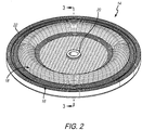
- FIG. 1 A perspective view of an illustrative double diaphragm pump 2 is shown in Fig. 1 . It is appreciated that either a single diaphragm or double diaphragm pump may employ the composite diaphragm of the present disclosure. Also, air operated, electric operated, or other means to drive the diaphragm may be employed as well. The skilled artisan, upon reading the present disclosure, will appreciate that the double diaphragm pump shown herein is for illustrative purposes. To that end, the illustrative double diaphragm pump 2 shown includes an inlet manifold 4, first and second fluid chambers 6 and 8, a drive mechanism 10, and an outlet manifold 12. A diaphragm, such as diaphragm 14 shown in Fig. 2 , is fitted into each of fluid chambers 6 and 8 and moves fluid from inlet manifold 4 to outlet manifold 12 as known by those skilled in the art.
- a diaphragm such as diaphragm 14 shown in Fig. 2
- diaphragm 14 is composed of a base layer 16 that forms the structural body of the diaphragm as shown.
- base layer 16 may be made of a compatible thermoplastic elastomer such as a poly ether block amide, thermoplastic vulcinizate (TPV) i.e., Santoprene with polyamide or Zeotherm alkyl acrylate copolymer (ACM) rubber plus polyamide, polyamide elastomers i.e., polyamide 12-block poly(tetramethylene ether) glycol (PTMEG), and polyamide based silicones.
- Top fabric layer 18 is a flexible Kevlar fabric that is applied onto base layer 16. Being flexible, the Kevlar of top layer 18 will conform to the shape of base layer 16.
- the Kevlar fabric of top layer 18 will be on the fluid-contact side of the diaphragm. This means that top layer 18 will be exposed to the fluid being pumped in from a fluid source through inlet manifold 4 and pumped out to outlet manifold 12 ( see, also, Fig. 1 ). It is this fluid that may contain media or other solids that has the potential to cause damage to the diaphragm. The Kevlar fabric of top layer 18 protects against that damage. It is also appreciated that the Kevlar may have chemical resistance to a wide range of chemicals which might help it in other applications ⁇ even where media and solids do not pose a risk.
- neck 20 and rim 22 of diaphragm 14 are shown in this view.
- neck 20 provides the structural support to engage a washer, fastener, or both, etc., that secures to the moving piston rod, screw, etc., that generates the reciprocal movement of diaphragm 14.
- rim 22 is the structural portion of diaphragm 14 that is held in place by the pump housing and fluid chamber head to keep the diaphragm in position and maintain a seal between the fluid chamber and the air or other motive fluid chamber that typical diaphragms segregate. It is appreciated that neither neck 20 or rim 22 necessarily require the Kevlar fabric of top layer 18. It will be appreciated by the skilled artisan upon reading this disclosure; however, that if deemed necessary because of the nature of the pump and/or the fluids being moved therethrough, top layer 18 may be applied to these structures as well.
- top layer 18 is laminated onto base layer 16.
- the fabric of top layer 18 may be applied to base layer 16 by such means as chemical bonding, chemical adhesion, or over molding with top layer 18.
- top layer 18 may be applied via adhesive or even a mechanical fastener.
- the elastomer of the diaphragm may migrate between the woven fibers of top layer 18 to further reinforce attachment of top layer 18 onto base layer 16.
- top layer 18 applied over rim 22 of base layer 16.
- rim 22 is configured to assist securing diaphragm 14 to the fluid chamber.
- top layer 18 may or may not extend over rim 22 of base layer 16.
- top layer 18 extends over rim 22 of base layer 16. But depending on the attachment characteristics, it may be advantageous for the fabric of top layer 18 not to extend over rim 22 in other embodiments. As such, the fabric of top layer 18 may be backed-off to expose base layer 16 at rim 22.
- top layer 18 is a separate Kevlar fabric layer distinguishable from the diaphragm structure body of base layer 16.
- the Kevlar fabric of top layer 18 is designed to withstand puncture and abrasion forces that may be applied to the diaphragm of base layer 16 when drawing in or pushing out fluid.
- top layer 18 is flexible enough to move with base layer 16 as diaphragm 14 is being pushed back and forth by a motive means creating the pumping action.
- neck 20 that surrounds bore 26 that receives a fastener or other structure to further secure diaphragm 14 onto the pump motive mechanism.
- opening 28 disposed through the Kevlar fabric of top layer 18 and is present for the same purposes.
- FIG. 5 A detailed cross dissection view of a portion of double diaphragm pump 2 is shown in Fig 5 .
- this view depicts the fluid chamber 6 portion of double diaphragm pump 2.
- a pump head 30 couples to a base 32 that forms fluid chamber cavity 34.
- Diaphragm 14 segregates fluid chamber cavity 34 into a pumped fluid-side portion 36 and non-pumped fluid-side portion 38.
- the pumped fluid-side portion 36 is the side where fluid being received through inlet manifold 4 enters fluid chamber 6 due to the movement of diaphragm 14.
- this is the side that requires top layer 18 since it is here the diaphragm will be susceptible to solids and other media that might otherwise damage diaphragm 14.
- Non-pumped fluid-side 38 may be used to receive motive fluid such as air or hydraulic fluid which assists moving diaphragm 14 to draw in and push out the fluid.
- washers 40 and 42 which sandwich diaphragm 14.
- Fastener 44 secures washers 40 and 42 onto diaphragm 14.
- fastener 44 secures those structures to a rod 46 which is either tied to another spaced apart diaphragm mechanism located in another fluid chambers (such as fluid chamber 8 shown in double diaphragm pump 2 and Fig. 2 ), or a motor or other structure to move diaphragm 14.
Landscapes
- Engineering & Computer Science (AREA)
- Mechanical Engineering (AREA)
- General Engineering & Computer Science (AREA)
- Reciprocating Pumps (AREA)
Claims (14)
- Eine Membran(14)-Pumpe, beinhaltend:eine Fluidkammer (6);eine in der Fluidkammer (6) befindliche Membran (14);wobei die Membran (14) eine biegsame scheibenförmige Struktur ist, die aus einem Elastomermaterial gefertigt ist;wobei die Membran (14) eine Außenkante aufweist;wobei die Membran (14) eine erste Oberfläche umfasst;gekennzeichnet durch eine Stoffschicht, die auf die erste Oberfläche der Membran (14) aufgebracht ist;wobei der Stoff aus gewebten Fasern auf Aramidbasis zusammengesetzt ist; undwobei der Stoff durch ein Mittel, ausgewählt aus der Gruppe, bestehend aus chemischer Bindung, chemischer Adhäsion, Überspritzen der Membran (14), einem Klebstoff und einem mechanischen Befestigungsmittel (44), auf die erste Oberfläche der Membran (14) aufgebracht ist.
- Membran(14)-Pumpe gemäß Anspruch 1, wobei die Membran(14)-Pumpe ferner einen Einlass, die mit dem Einlass in Fluidkommunikation stehende Fluidkammer (6) und einen Auslass in Fluidkommunikation mit der Fluidkammer (6) beinhaltet.
- Membran(14)-Pumpe gemäß Anspruch 1 oder 2, wobei die Fluidkammer (6) einen ersten Abschnitt und einen zweiten Abschnitt umfasst und wobei sich Fluid von einer Fluidquelle durch den ersten Abschnitt der Fluidkammer (6) bewegt.
- Membran(14)-Pumpe gemäß Anspruch 3, wobei die Membran (14) den ersten Abschnitt der Fluidkammer (6) von dem zweiten Abschnitt der Fluidkammer (6) trennt.
- Membran(14)-Pumpe gemäß Anspruch 4, wobei die erste Oberfläche der Membran (14) dem ersten Abschnitt der Fluidkammer (6) zugewandt ist und die Membran (14) eine zweite Oberfläche umfasst, die dem zweiten Abschnitt der Fluidkammer (6) zugewandt ist.
- Membran(14)-Pumpe gemäß Anspruch 5, wobei der Stoff auf die erste Oberfläche der Membran (14), die dem ersten Abschnitt zugewandt ist, aufgebracht ist, sodass der Stoff dem Fluid zugewandt ist, das durch den ersten Abschnitt der Fluidkammer (6) bewegt wird.
- Membran(14)-Pumpe gemäß einem der Ansprüche 3-6, wobei der Stoff als eine Barriere zwischen dem ersten Abschnitt der Fluidkammer (6) und der Membran (14) dient.
- Membran(14)-Pumpe gemäß einem der Ansprüche 3-7, wobei die Membran (14) eine Öffnung (28) umfasst, die durch die Membran (14) angeordnet ist, um an eine Bewegungsquelle, die die Membran (14) alternierend in Richtung des ersten Abschnitts und weg von dem zweiten Abschnitt hin- und hergehend bewegt, zu koppeln.
- Membran(14)-Pumpe gemäß einem der vorhergehenden Ansprüche, wobei die Membran (14) eine Außenkante aufweist, die konfiguriert ist, um von der Fluidkammer (6) gehalten zu werden.
- Membran(14)-Pumpe gemäß einem der vorhergehenden Ansprüche, wobei die Membran (14) eine Öffnung (28) umfasst, die durch die Membran (14) angeordnet ist, und der Stoff um die Öffnung (28) herum auf die Membran (14) aufgebracht ist.
- Membran(14)-Pumpe gemäß einem der vorhergehenden Ansprüche, wobei die Membran(14)-Pumpe eine Doppelmembranpumpe (2) ist.
- Eine Membran (14) zur Verwendung in einer Pumpe, wobei die Membran (14) Folgendes beinhaltet:einen biegsamen scheibenförmigen Körper, der eine erste Oberfläche und eine Außenkante aufweist;wobei der scheibenförmige biegsame Körper aus einem Elastomermaterial gefertigt ist; undgekennzeichnet durch eine Stoffschicht, die auf die erste Oberfläche des scheibenförmigen biegsamen Körpers aufgebracht ist; undwobei der Stoff aus gewebten Fasern auf Aramidbasis zusammengesetzt ist;wobei der Stoff durch ein Mittel, ausgewählt aus der Gruppe, bestehend aus chemischer Bindung, chemischer Adhäsion, Überspritzen der Membran (14), einem Klebstoff und einem mechanischen Befestigungsmittel (44), auf die erste Oberfläche der Membran (14) aufgebracht ist.
- Membran(14)-Pumpe oder Membran (14) gemäß einem der vorhergehenden Ansprüche, wobei die Membran (14) aus einem Material, ausgewählt aus der Gruppe, bestehend aus Polyamid und einem Polyetherblockamid, gefertigt ist.
- Membran(14)-Pumpe oder Membran (14) gemäß einem der vorhergehenden Ansprüche, wobei der Stoff so auf die Membran (14) aufgebracht ist, dass sich das Elastomer der Membran (14) in Öffnungen befindet, die zwischen Fasern des Stoffs gebildet sind.
Applications Claiming Priority (1)
| Application Number | Priority Date | Filing Date | Title |
|---|---|---|---|
| US15/807,785 US10527033B2 (en) | 2017-11-09 | 2017-11-09 | Abrasion and puncture resistant diaphragm |
Publications (2)
| Publication Number | Publication Date |
|---|---|
| EP3483439A1 EP3483439A1 (de) | 2019-05-15 |
| EP3483439B1 true EP3483439B1 (de) | 2021-10-27 |
Family
ID=64267569
Family Applications (1)
| Application Number | Title | Priority Date | Filing Date |
|---|---|---|---|
| EP18204744.9A Not-in-force EP3483439B1 (de) | 2017-11-09 | 2018-11-06 | Abrieb- und durchstichfeste membran |
Country Status (3)
| Country | Link |
|---|---|
| US (1) | US10527033B2 (de) |
| EP (1) | EP3483439B1 (de) |
| CN (1) | CN109763965B (de) |
Families Citing this family (3)
| Publication number | Priority date | Publication date | Assignee | Title |
|---|---|---|---|---|
| US11767840B2 (en) | 2021-01-25 | 2023-09-26 | Ingersoll-Rand Industrial U.S. | Diaphragm pump |
| DE102023117879A1 (de) * | 2023-07-06 | 2025-01-09 | Prominent Gmbh | Dosiermembran |
| DE102024119053A1 (de) * | 2024-07-04 | 2026-01-08 | Ulman Dichtungstechnik Gmbh | Verbundmembran insbesondere für Membranpumpen |
Family Cites Families (29)
| Publication number | Priority date | Publication date | Assignee | Title |
|---|---|---|---|---|
| US1515702A (en) | 1922-05-24 | 1924-11-18 | Dorr Co | Pump diaphragm |
| US2564693A (en) | 1947-08-20 | 1951-08-21 | Beloit Iron Works | Diaphragm construction |
| US3652187A (en) * | 1970-10-29 | 1972-03-28 | Amicon Corp | Pump |
| US4989497A (en) | 1985-08-30 | 1991-02-05 | The United States Of America As Represented By The Administrator Of The National Aeronautics And Space Administration | Flexible diaphragm-extreme temperature usage |
| US4837068A (en) | 1987-01-27 | 1989-06-06 | The Foxboro Company | Compliant diaphragm material |
| US4950499A (en) | 1987-01-27 | 1990-08-21 | The Foxboro Company | Method of making a compliant fluid-impermeable element |
| US5093067A (en) * | 1988-03-14 | 1992-03-03 | Allied-Signal Inc. | Injection molding of fabric reinforced elastomeric diaphragms |
| US5052276A (en) | 1990-06-18 | 1991-10-01 | Halsey George H | Diaphragm construction |
| US5217797A (en) * | 1992-02-19 | 1993-06-08 | W. L. Gore & Associates, Inc. | Chemically resistant diaphragm |
| US5391060A (en) | 1993-05-14 | 1995-02-21 | The Aro Corporation | Air operated double diaphragm pump |
| CA2180413A1 (en) | 1996-05-06 | 1997-11-07 | Eldon S. Eady | Abrasion resistant plastic bonded to a diaphragm |
| EP0898076A1 (de) | 1997-08-19 | 1999-02-24 | Westinghouse Air Brake Company | Membran mit geklebter abrasionsbeständiger Kunststoffschicht |
| US5996470A (en) | 1997-11-18 | 1999-12-07 | Westinghouse Air Brake Company | Wear ring for diaphragm and outer piston |
| US6067893A (en) | 1998-03-10 | 2000-05-30 | Westinghouse Air Brake Company | Ribbed diaphragm |
| CN2321956Y (zh) * | 1998-04-21 | 1999-06-02 | 杭州华黎泵厂 | 机械驱动式隔膜计量泵 |
| US6106246A (en) * | 1998-10-05 | 2000-08-22 | Trebor International, Inc. | Free-diaphragm pump |
| US6205907B1 (en) | 1999-03-22 | 2001-03-27 | Thermotion Corporation | Method of making fiber reinforced elastomeric diaphragms and fiber reinforced diaphragms |
| AT411257B (de) | 2001-11-07 | 2003-11-25 | Hoerbiger Kompressortech Serv | Dichtelemente für kompressorventile |
| US6722262B2 (en) * | 2002-03-06 | 2004-04-20 | Honeywell International, Inc. | Pneumatic actuator with a nested diaphragm assembly |
| US6883417B2 (en) | 2003-03-19 | 2005-04-26 | Ingersoll-Rand Company | Connecting configuration for a diaphragm in a diaphragm pump |
| CN2620110Y (zh) * | 2003-04-17 | 2004-06-09 | 宜兴市宙斯泵业有限公司 | 一种改进的液体介质隔膜变容泵 |
| DE102004047720A1 (de) | 2003-11-03 | 2005-04-21 | Trelleborg Sealing Solutions U | Vorrichtung mit einer Membran sowie ein Verfahren zum Herstellen |
| US20070044653A1 (en) * | 2005-08-25 | 2007-03-01 | Honeywell International, Inc. | Pneumatic diaphragm having a bias weave pattern |
| EP2649326A1 (de) | 2010-12-07 | 2013-10-16 | General Compression Inc. | Verdichter und/oder expander mit rollkolbendichtung |
| CN107383710A (zh) | 2011-08-25 | 2017-11-24 | 大金工业株式会社 | 隔膜 |
| US9976016B2 (en) | 2012-02-24 | 2018-05-22 | Daikin Industries, Ltd. | Fluororubber composition |
| US9845794B2 (en) | 2013-10-08 | 2017-12-19 | Ingersoll-Rand Company | Hydraulically actuated diaphragm pumps |
| CN205225649U (zh) * | 2015-11-18 | 2016-05-11 | 上海隆胜堡密封科技有限公司 | 一种隔膜泵复合环保膜片 |
| CN205779587U (zh) * | 2016-06-18 | 2016-12-07 | 浙江爱力浦科技股份有限公司 | 一种泵头密封装置 |
-
2017
- 2017-11-09 US US15/807,785 patent/US10527033B2/en not_active Expired - Fee Related
-
2018
- 2018-11-06 EP EP18204744.9A patent/EP3483439B1/de not_active Not-in-force
- 2018-11-08 CN CN201811324254.3A patent/CN109763965B/zh not_active Expired - Fee Related
Also Published As
| Publication number | Publication date |
|---|---|
| CN109763965A (zh) | 2019-05-17 |
| EP3483439A1 (de) | 2019-05-15 |
| US10527033B2 (en) | 2020-01-07 |
| US20190136844A1 (en) | 2019-05-09 |
| CN109763965B (zh) | 2021-03-09 |
Similar Documents
| Publication | Publication Date | Title |
|---|---|---|
| US7905172B2 (en) | Laminate membrane | |
| EP0704024B1 (de) | Pumpendiaphragma | |
| US6145430A (en) | Selectively bonded pump diaphragm | |
| US5894784A (en) | Backup washers for diaphragms and diaphragm pump incorporating same | |
| US10527033B2 (en) | Abrasion and puncture resistant diaphragm | |
| US5615597A (en) | Composite diaphragm for diaphragm pumps having two different shore-hardness materials | |
| US5217797A (en) | Chemically resistant diaphragm | |
| US6343539B1 (en) | Multiple layer pump diaphragm | |
| EP1323924A2 (de) | Zum Teil vorgespannte Pumpenmembran | |
| US5816133A (en) | Composite diaphragm for diaphragm pumps | |
| EP1097304A1 (de) | Luftgetriebene pumpen und ihre bauteile | |
| EP3983679B1 (de) | Kontraktionsvorrichtung zur verwendung als aktuator, pumpe oder kompressor | |
| CN102099606A (zh) | 止回阀结构、隔膜泵以及血压计 | |
| US20180202474A1 (en) | Hydraulic actuator | |
| US20030209138A1 (en) | Enhanced wobble plated driven diaphragm pump | |
| EP0733176A1 (de) | Speicherkolben mit mehrfachelastomerverdichtung | |
| US7424847B2 (en) | Diaphragm assembly for a pump | |
| CA2241250C (en) | Ribbed diaphragm | |
| CN111989488B (zh) | 用于保护隔膜泵免受压差影响的装置 | |
| US20180172161A1 (en) | Sealing ring of a translationally adjustable component | |
| US11754181B2 (en) | Overmolded diaphragm for use in a pump | |
| CN216866986U (zh) | 砼活塞、砼活塞组件、泵送系统和作业机械 | |
| CN111065819A (zh) | 旋转隔膜正排量泵 | |
| GB2564678B (en) | A rotary diaphragm positive displacement pump | |
| GB2564681A (en) | A rotary diaphragm positive displacement pump |
Legal Events
| Date | Code | Title | Description |
|---|---|---|---|
| PUAI | Public reference made under article 153(3) epc to a published international application that has entered the european phase |
Free format text: ORIGINAL CODE: 0009012 |
|
| STAA | Information on the status of an ep patent application or granted ep patent |
Free format text: STATUS: REQUEST FOR EXAMINATION WAS MADE |
|
| 17P | Request for examination filed |
Effective date: 20181106 |
|
| AK | Designated contracting states |
Kind code of ref document: A1 Designated state(s): AL AT BE BG CH CY CZ DE DK EE ES FI FR GB GR HR HU IE IS IT LI LT LU LV MC MK MT NL NO PL PT RO RS SE SI SK SM TR |
|
| AX | Request for extension of the european patent |
Extension state: BA ME |
|
| RAP1 | Party data changed (applicant data changed or rights of an application transferred) |
Owner name: INGERSOLL-RAND INDUSTRIAL U.S., INC. |
|
| REG | Reference to a national code |
Ref country code: DE Ref legal event code: R079 Ref document number: 602018025616 Country of ref document: DE Free format text: PREVIOUS MAIN CLASS: F04B0043000000 Ipc: F04B0043060000 |
|
| GRAP | Despatch of communication of intention to grant a patent |
Free format text: ORIGINAL CODE: EPIDOSNIGR1 |
|
| STAA | Information on the status of an ep patent application or granted ep patent |
Free format text: STATUS: GRANT OF PATENT IS INTENDED |
|
| RIC1 | Information provided on ipc code assigned before grant |
Ipc: F04B 43/00 20060101ALI20210415BHEP Ipc: F04B 43/06 20060101AFI20210415BHEP |
|
| INTG | Intention to grant announced |
Effective date: 20210506 |
|
| GRAS | Grant fee paid |
Free format text: ORIGINAL CODE: EPIDOSNIGR3 |
|
| GRAA | (expected) grant |
Free format text: ORIGINAL CODE: 0009210 |
|
| STAA | Information on the status of an ep patent application or granted ep patent |
Free format text: STATUS: THE PATENT HAS BEEN GRANTED |
|
| AK | Designated contracting states |
Kind code of ref document: B1 Designated state(s): AL AT BE BG CH CY CZ DE DK EE ES FI FR GB GR HR HU IE IS IT LI LT LU LV MC MK MT NL NO PL PT RO RS SE SI SK SM TR |
|
| REG | Reference to a national code |
Ref country code: GB Ref legal event code: FG4D |
|
| REG | Reference to a national code |
Ref country code: CH Ref legal event code: EP |
|
| REG | Reference to a national code |
Ref country code: AT Ref legal event code: REF Ref document number: 1442030 Country of ref document: AT Kind code of ref document: T Effective date: 20211115 |
|
| REG | Reference to a national code |
Ref country code: DE Ref legal event code: R096 Ref document number: 602018025616 Country of ref document: DE |
|
| REG | Reference to a national code |
Ref country code: IE Ref legal event code: FG4D |
|
| REG | Reference to a national code |
Ref country code: LT Ref legal event code: MG9D |
|
| REG | Reference to a national code |
Ref country code: NL Ref legal event code: MP Effective date: 20211027 |
|
| REG | Reference to a national code |
Ref country code: AT Ref legal event code: MK05 Ref document number: 1442030 Country of ref document: AT Kind code of ref document: T Effective date: 20211027 |
|
| PG25 | Lapsed in a contracting state [announced via postgrant information from national office to epo] |
Ref country code: RS Free format text: LAPSE BECAUSE OF FAILURE TO SUBMIT A TRANSLATION OF THE DESCRIPTION OR TO PAY THE FEE WITHIN THE PRESCRIBED TIME-LIMIT Effective date: 20211027 Ref country code: LT Free format text: LAPSE BECAUSE OF FAILURE TO SUBMIT A TRANSLATION OF THE DESCRIPTION OR TO PAY THE FEE WITHIN THE PRESCRIBED TIME-LIMIT Effective date: 20211027 Ref country code: FI Free format text: LAPSE BECAUSE OF FAILURE TO SUBMIT A TRANSLATION OF THE DESCRIPTION OR TO PAY THE FEE WITHIN THE PRESCRIBED TIME-LIMIT Effective date: 20211027 Ref country code: BG Free format text: LAPSE BECAUSE OF FAILURE TO SUBMIT A TRANSLATION OF THE DESCRIPTION OR TO PAY THE FEE WITHIN THE PRESCRIBED TIME-LIMIT Effective date: 20220127 Ref country code: AT Free format text: LAPSE BECAUSE OF FAILURE TO SUBMIT A TRANSLATION OF THE DESCRIPTION OR TO PAY THE FEE WITHIN THE PRESCRIBED TIME-LIMIT Effective date: 20211027 |
|
| PG25 | Lapsed in a contracting state [announced via postgrant information from national office to epo] |
Ref country code: IS Free format text: LAPSE BECAUSE OF FAILURE TO SUBMIT A TRANSLATION OF THE DESCRIPTION OR TO PAY THE FEE WITHIN THE PRESCRIBED TIME-LIMIT Effective date: 20220227 Ref country code: SE Free format text: LAPSE BECAUSE OF FAILURE TO SUBMIT A TRANSLATION OF THE DESCRIPTION OR TO PAY THE FEE WITHIN THE PRESCRIBED TIME-LIMIT Effective date: 20211027 Ref country code: PT Free format text: LAPSE BECAUSE OF FAILURE TO SUBMIT A TRANSLATION OF THE DESCRIPTION OR TO PAY THE FEE WITHIN THE PRESCRIBED TIME-LIMIT Effective date: 20220228 Ref country code: PL Free format text: LAPSE BECAUSE OF FAILURE TO SUBMIT A TRANSLATION OF THE DESCRIPTION OR TO PAY THE FEE WITHIN THE PRESCRIBED TIME-LIMIT Effective date: 20211027 Ref country code: NO Free format text: LAPSE BECAUSE OF FAILURE TO SUBMIT A TRANSLATION OF THE DESCRIPTION OR TO PAY THE FEE WITHIN THE PRESCRIBED TIME-LIMIT Effective date: 20220127 Ref country code: NL Free format text: LAPSE BECAUSE OF FAILURE TO SUBMIT A TRANSLATION OF THE DESCRIPTION OR TO PAY THE FEE WITHIN THE PRESCRIBED TIME-LIMIT Effective date: 20211027 Ref country code: LV Free format text: LAPSE BECAUSE OF FAILURE TO SUBMIT A TRANSLATION OF THE DESCRIPTION OR TO PAY THE FEE WITHIN THE PRESCRIBED TIME-LIMIT Effective date: 20211027 Ref country code: HR Free format text: LAPSE BECAUSE OF FAILURE TO SUBMIT A TRANSLATION OF THE DESCRIPTION OR TO PAY THE FEE WITHIN THE PRESCRIBED TIME-LIMIT Effective date: 20211027 Ref country code: GR Free format text: LAPSE BECAUSE OF FAILURE TO SUBMIT A TRANSLATION OF THE DESCRIPTION OR TO PAY THE FEE WITHIN THE PRESCRIBED TIME-LIMIT Effective date: 20220128 Ref country code: ES Free format text: LAPSE BECAUSE OF FAILURE TO SUBMIT A TRANSLATION OF THE DESCRIPTION OR TO PAY THE FEE WITHIN THE PRESCRIBED TIME-LIMIT Effective date: 20211027 |
|
| REG | Reference to a national code |
Ref country code: DE Ref legal event code: R119 Ref document number: 602018025616 Country of ref document: DE |
|
| REG | Reference to a national code |
Ref country code: CH Ref legal event code: PL |
|
| PG25 | Lapsed in a contracting state [announced via postgrant information from national office to epo] |
Ref country code: SM Free format text: LAPSE BECAUSE OF FAILURE TO SUBMIT A TRANSLATION OF THE DESCRIPTION OR TO PAY THE FEE WITHIN THE PRESCRIBED TIME-LIMIT Effective date: 20211027 Ref country code: SK Free format text: LAPSE BECAUSE OF FAILURE TO SUBMIT A TRANSLATION OF THE DESCRIPTION OR TO PAY THE FEE WITHIN THE PRESCRIBED TIME-LIMIT Effective date: 20211027 Ref country code: RO Free format text: LAPSE BECAUSE OF FAILURE TO SUBMIT A TRANSLATION OF THE DESCRIPTION OR TO PAY THE FEE WITHIN THE PRESCRIBED TIME-LIMIT Effective date: 20211027 Ref country code: MC Free format text: LAPSE BECAUSE OF FAILURE TO SUBMIT A TRANSLATION OF THE DESCRIPTION OR TO PAY THE FEE WITHIN THE PRESCRIBED TIME-LIMIT Effective date: 20211027 Ref country code: LU Free format text: LAPSE BECAUSE OF NON-PAYMENT OF DUE FEES Effective date: 20211106 Ref country code: EE Free format text: LAPSE BECAUSE OF FAILURE TO SUBMIT A TRANSLATION OF THE DESCRIPTION OR TO PAY THE FEE WITHIN THE PRESCRIBED TIME-LIMIT Effective date: 20211027 Ref country code: DK Free format text: LAPSE BECAUSE OF FAILURE TO SUBMIT A TRANSLATION OF THE DESCRIPTION OR TO PAY THE FEE WITHIN THE PRESCRIBED TIME-LIMIT Effective date: 20211027 Ref country code: CZ Free format text: LAPSE BECAUSE OF FAILURE TO SUBMIT A TRANSLATION OF THE DESCRIPTION OR TO PAY THE FEE WITHIN THE PRESCRIBED TIME-LIMIT Effective date: 20211027 Ref country code: BE Free format text: LAPSE BECAUSE OF NON-PAYMENT OF DUE FEES Effective date: 20211130 |
|
| REG | Reference to a national code |
Ref country code: BE Ref legal event code: MM Effective date: 20211130 |
|
| PG25 | Lapsed in a contracting state [announced via postgrant information from national office to epo] |
Ref country code: LI Free format text: LAPSE BECAUSE OF NON-PAYMENT OF DUE FEES Effective date: 20211130 Ref country code: CH Free format text: LAPSE BECAUSE OF NON-PAYMENT OF DUE FEES Effective date: 20211130 |
|
| PLBE | No opposition filed within time limit |
Free format text: ORIGINAL CODE: 0009261 |
|
| STAA | Information on the status of an ep patent application or granted ep patent |
Free format text: STATUS: NO OPPOSITION FILED WITHIN TIME LIMIT |
|
| 26N | No opposition filed |
Effective date: 20220728 |
|
| PG25 | Lapsed in a contracting state [announced via postgrant information from national office to epo] |
Ref country code: IE Free format text: LAPSE BECAUSE OF NON-PAYMENT OF DUE FEES Effective date: 20211106 Ref country code: DE Free format text: LAPSE BECAUSE OF NON-PAYMENT OF DUE FEES Effective date: 20220601 Ref country code: AL Free format text: LAPSE BECAUSE OF FAILURE TO SUBMIT A TRANSLATION OF THE DESCRIPTION OR TO PAY THE FEE WITHIN THE PRESCRIBED TIME-LIMIT Effective date: 20211027 |
|
| PG25 | Lapsed in a contracting state [announced via postgrant information from national office to epo] |
Ref country code: SI Free format text: LAPSE BECAUSE OF FAILURE TO SUBMIT A TRANSLATION OF THE DESCRIPTION OR TO PAY THE FEE WITHIN THE PRESCRIBED TIME-LIMIT Effective date: 20211027 Ref country code: FR Free format text: LAPSE BECAUSE OF NON-PAYMENT OF DUE FEES Effective date: 20211227 |
|
| PG25 | Lapsed in a contracting state [announced via postgrant information from national office to epo] |
Ref country code: IT Free format text: LAPSE BECAUSE OF FAILURE TO SUBMIT A TRANSLATION OF THE DESCRIPTION OR TO PAY THE FEE WITHIN THE PRESCRIBED TIME-LIMIT Effective date: 20211027 |
|
| PG25 | Lapsed in a contracting state [announced via postgrant information from national office to epo] |
Ref country code: CY Free format text: LAPSE BECAUSE OF FAILURE TO SUBMIT A TRANSLATION OF THE DESCRIPTION OR TO PAY THE FEE WITHIN THE PRESCRIBED TIME-LIMIT Effective date: 20211027 |
|
| GBPC | Gb: european patent ceased through non-payment of renewal fee |
Effective date: 20221106 |
|
| PG25 | Lapsed in a contracting state [announced via postgrant information from national office to epo] |
Ref country code: HU Free format text: LAPSE BECAUSE OF FAILURE TO SUBMIT A TRANSLATION OF THE DESCRIPTION OR TO PAY THE FEE WITHIN THE PRESCRIBED TIME-LIMIT; INVALID AB INITIO Effective date: 20181106 |
|
| PG25 | Lapsed in a contracting state [announced via postgrant information from national office to epo] |
Ref country code: GB Free format text: LAPSE BECAUSE OF NON-PAYMENT OF DUE FEES Effective date: 20221106 |
|
| PG25 | Lapsed in a contracting state [announced via postgrant information from national office to epo] |
Ref country code: MK Free format text: LAPSE BECAUSE OF FAILURE TO SUBMIT A TRANSLATION OF THE DESCRIPTION OR TO PAY THE FEE WITHIN THE PRESCRIBED TIME-LIMIT Effective date: 20211027 |
|
| PG25 | Lapsed in a contracting state [announced via postgrant information from national office to epo] |
Ref country code: MT Free format text: LAPSE BECAUSE OF FAILURE TO SUBMIT A TRANSLATION OF THE DESCRIPTION OR TO PAY THE FEE WITHIN THE PRESCRIBED TIME-LIMIT Effective date: 20211027 |
|
| PG25 | Lapsed in a contracting state [announced via postgrant information from national office to epo] |
Ref country code: TR Free format text: LAPSE BECAUSE OF FAILURE TO SUBMIT A TRANSLATION OF THE DESCRIPTION OR TO PAY THE FEE WITHIN THE PRESCRIBED TIME-LIMIT Effective date: 20211027 |