EP3483391A1 - Turbinenschaufel eines turbinen-laufschaufelkranzes - Google Patents
Turbinenschaufel eines turbinen-laufschaufelkranzes Download PDFInfo
- Publication number
- EP3483391A1 EP3483391A1 EP18204562.5A EP18204562A EP3483391A1 EP 3483391 A1 EP3483391 A1 EP 3483391A1 EP 18204562 A EP18204562 A EP 18204562A EP 3483391 A1 EP3483391 A1 EP 3483391A1
- Authority
- EP
- European Patent Office
- Prior art keywords
- turbine blade
- cooling air
- cross
- section
- sectional area
- Prior art date
- Legal status (The legal status is an assumption and is not a legal conclusion. Google has not performed a legal analysis and makes no representation as to the accuracy of the status listed.)
- Granted
Links
Images




Classifications
-
- F—MECHANICAL ENGINEERING; LIGHTING; HEATING; WEAPONS; BLASTING
- F01—MACHINES OR ENGINES IN GENERAL; ENGINE PLANTS IN GENERAL; STEAM ENGINES
- F01D—NON-POSITIVE DISPLACEMENT MACHINES OR ENGINES, e.g. STEAM TURBINES
- F01D5/00—Blades; Blade-carrying members; Heating, heat-insulating, cooling or antivibration means on the blades or the members
- F01D5/12—Blades
- F01D5/14—Form or construction
- F01D5/18—Hollow blades, i.e. blades with cooling or heating channels or cavities; Heating, heat-insulating or cooling means on blades
- F01D5/187—Convection cooling
-
- F—MECHANICAL ENGINEERING; LIGHTING; HEATING; WEAPONS; BLASTING
- F01—MACHINES OR ENGINES IN GENERAL; ENGINE PLANTS IN GENERAL; STEAM ENGINES
- F01D—NON-POSITIVE DISPLACEMENT MACHINES OR ENGINES, e.g. STEAM TURBINES
- F01D5/00—Blades; Blade-carrying members; Heating, heat-insulating, cooling or antivibration means on the blades or the members
- F01D5/02—Blade-carrying members, e.g. rotors
- F01D5/08—Heating, heat-insulating or cooling means
- F01D5/081—Cooling fluid being directed on the side of the rotor disc or at the roots of the blades
-
- F—MECHANICAL ENGINEERING; LIGHTING; HEATING; WEAPONS; BLASTING
- F01—MACHINES OR ENGINES IN GENERAL; ENGINE PLANTS IN GENERAL; STEAM ENGINES
- F01D—NON-POSITIVE DISPLACEMENT MACHINES OR ENGINES, e.g. STEAM TURBINES
- F01D5/00—Blades; Blade-carrying members; Heating, heat-insulating, cooling or antivibration means on the blades or the members
- F01D5/12—Blades
- F01D5/14—Form or construction
- F01D5/141—Shape, i.e. outer, aerodynamic form
- F01D5/142—Shape, i.e. outer, aerodynamic form of the blades of successive rotor or stator blade-rows
- F01D5/143—Contour of the outer or inner working fluid flow path wall, i.e. shroud or hub contour
-
- F—MECHANICAL ENGINEERING; LIGHTING; HEATING; WEAPONS; BLASTING
- F01—MACHINES OR ENGINES IN GENERAL; ENGINE PLANTS IN GENERAL; STEAM ENGINES
- F01D—NON-POSITIVE DISPLACEMENT MACHINES OR ENGINES, e.g. STEAM TURBINES
- F01D5/00—Blades; Blade-carrying members; Heating, heat-insulating, cooling or antivibration means on the blades or the members
- F01D5/12—Blades
- F01D5/14—Form or construction
- F01D5/141—Shape, i.e. outer, aerodynamic form
- F01D5/145—Means for influencing boundary layers or secondary circulations
-
- F—MECHANICAL ENGINEERING; LIGHTING; HEATING; WEAPONS; BLASTING
- F01—MACHINES OR ENGINES IN GENERAL; ENGINE PLANTS IN GENERAL; STEAM ENGINES
- F01D—NON-POSITIVE DISPLACEMENT MACHINES OR ENGINES, e.g. STEAM TURBINES
- F01D5/00—Blades; Blade-carrying members; Heating, heat-insulating, cooling or antivibration means on the blades or the members
- F01D5/12—Blades
- F01D5/14—Form or construction
- F01D5/18—Hollow blades, i.e. blades with cooling or heating channels or cavities; Heating, heat-insulating or cooling means on blades
-
- F—MECHANICAL ENGINEERING; LIGHTING; HEATING; WEAPONS; BLASTING
- F01—MACHINES OR ENGINES IN GENERAL; ENGINE PLANTS IN GENERAL; STEAM ENGINES
- F01D—NON-POSITIVE DISPLACEMENT MACHINES OR ENGINES, e.g. STEAM TURBINES
- F01D5/00—Blades; Blade-carrying members; Heating, heat-insulating, cooling or antivibration means on the blades or the members
- F01D5/12—Blades
- F01D5/14—Form or construction
- F01D5/18—Hollow blades, i.e. blades with cooling or heating channels or cavities; Heating, heat-insulating or cooling means on blades
- F01D5/186—Film cooling
-
- F—MECHANICAL ENGINEERING; LIGHTING; HEATING; WEAPONS; BLASTING
- F05—INDEXING SCHEMES RELATING TO ENGINES OR PUMPS IN VARIOUS SUBCLASSES OF CLASSES F01-F04
- F05D—INDEXING SCHEME FOR ASPECTS RELATING TO NON-POSITIVE-DISPLACEMENT MACHINES OR ENGINES, GAS-TURBINES OR JET-PROPULSION PLANTS
- F05D2220/00—Application
- F05D2220/30—Application in turbines
- F05D2220/32—Application in turbines in gas turbines
- F05D2220/323—Application in turbines in gas turbines for aircraft propulsion, e.g. jet engines
-
- F—MECHANICAL ENGINEERING; LIGHTING; HEATING; WEAPONS; BLASTING
- F05—INDEXING SCHEMES RELATING TO ENGINES OR PUMPS IN VARIOUS SUBCLASSES OF CLASSES F01-F04
- F05D—INDEXING SCHEME FOR ASPECTS RELATING TO NON-POSITIVE-DISPLACEMENT MACHINES OR ENGINES, GAS-TURBINES OR JET-PROPULSION PLANTS
- F05D2240/00—Components
- F05D2240/20—Rotors
- F05D2240/30—Characteristics of rotor blades, i.e. of any element transforming dynamic fluid energy to or from rotational energy and being attached to a rotor
- F05D2240/301—Cross-sectional characteristics
-
- F—MECHANICAL ENGINEERING; LIGHTING; HEATING; WEAPONS; BLASTING
- F05—INDEXING SCHEMES RELATING TO ENGINES OR PUMPS IN VARIOUS SUBCLASSES OF CLASSES F01-F04
- F05D—INDEXING SCHEME FOR ASPECTS RELATING TO NON-POSITIVE-DISPLACEMENT MACHINES OR ENGINES, GAS-TURBINES OR JET-PROPULSION PLANTS
- F05D2260/00—Function
- F05D2260/20—Heat transfer, e.g. cooling
- F05D2260/201—Heat transfer, e.g. cooling by impingement of a fluid
-
- F—MECHANICAL ENGINEERING; LIGHTING; HEATING; WEAPONS; BLASTING
- F05—INDEXING SCHEMES RELATING TO ENGINES OR PUMPS IN VARIOUS SUBCLASSES OF CLASSES F01-F04
- F05D—INDEXING SCHEME FOR ASPECTS RELATING TO NON-POSITIVE-DISPLACEMENT MACHINES OR ENGINES, GAS-TURBINES OR JET-PROPULSION PLANTS
- F05D2260/00—Function
- F05D2260/20—Heat transfer, e.g. cooling
- F05D2260/202—Heat transfer, e.g. cooling by film cooling
-
- F—MECHANICAL ENGINEERING; LIGHTING; HEATING; WEAPONS; BLASTING
- F05—INDEXING SCHEMES RELATING TO ENGINES OR PUMPS IN VARIOUS SUBCLASSES OF CLASSES F01-F04
- F05D—INDEXING SCHEME FOR ASPECTS RELATING TO NON-POSITIVE-DISPLACEMENT MACHINES OR ENGINES, GAS-TURBINES OR JET-PROPULSION PLANTS
- F05D2260/00—Function
- F05D2260/94—Functionality given by mechanical stress related aspects such as low cycle fatigue [LCF] of high cycle fatigue [HCF]
- F05D2260/941—Functionality given by mechanical stress related aspects such as low cycle fatigue [LCF] of high cycle fatigue [HCF] particularly aimed at mechanical or thermal stress reduction
Definitions
- the invention relates to a turbine blade of a turbine blade ring according to the preamble of patent claim 1 and a method for transporting a cooling medium in a turbine blade of a turbine blade ring.
- a cooling air duct of a turbine blade has a profile in at least one section such that its cross-sectional area increases in the flow direction of the cooling medium in a first, widening section to a maximum, then in a second , narrowing section is again reduced behind the maximum and while the cooling medium in the second, narrowing section is accelerated with a direction component in the direction of the suction side of the turbine blade. It is provided that the cooling air channel in the region of the maximum forms a bulge in the direction of the pressure side, wherein the cooling medium is deflected in the first section in the direction of the pressure side and in the second section in the direction of the suction side.
- the present invention is based on the idea of first delaying the cooling medium in the first expanding section and then accelerating it in the second, narrowing section, thereby forming the cooling air channel in such a way that the cooling medium absorbs during acceleration narrowing second section undergoes, is deflected in the direction of the suction side of the turbine disk.
- the effect of the Coriolis force which accelerates the cooling medium during the rotation of the turbine blade in the direction of the pressure side, at least partially compensated.
- the cooling medium can thereby improve flow in the cooling air duct, wherein nevertheless the heat transfer over all walls of the cooling air duct is made uniform. As a result, there is a more homogeneous temperature distribution and improved cooling of the turbine blade.
- the more homogeneous temperature distribution also reduces thermally induced stresses in the turbine disk material.
- the cooling air channel is shaped such that it forms a bulge in the direction of the pressure side in the region of the maximum, ie only in the direction of the pressure side or stronger Direction of the pressure side as is bulged in the direction of the suction side.
- This shaping of the first section causes the cooling medium in the first Part section guided in the direction of the pressure side and thereby can be accelerated or deflected in the second section effectively in the direction of the suction side.
- the invention leads to a bulge of the cooling air channel, which is formed by the widening and narrowing sections.
- x indicates the axial direction
- r the radial direction
- ⁇ the angle in the circumferential direction.
- the axial direction is usually identical to the machine axis of a gas turbine or a turbofan engine, in which the invention is realized.
- the radial direction points radially outward.
- Terms such as “ahead,” “behind,” “front,” and “rear” refer to the axial direction or flow direction in the gas turbine or cooling air passage described herein.
- the term “before” thus means “upstream” and the term “behind” means “downstream”.
- Terms such as “outer” or “inner” refer to the radial direction.
- the geometric course of a cooling air duct is expediently described herein by way of its center line, which represents the connecting line of all geometrical centers (area centroids) of the cross-sectional areas of the cooling air duct.
- a representative of the flow cross-sectional area of the cooling air channel is defined so that the center line of the cooling air channel penetrates the plane of the cross-sectional area always perpendicular.
- the normal vector of such a cross-sectional area corresponds to the tangent vector to the center line in the geometric center (area centroid) of the respective cross-sectional area.
- the cooling air channel has a first cross-sectional area A1 at the beginning of the widening section, a second cross-sectional area A2 at the end of the narrowing section, and a third cross-sectional area A3 at the maximum.
- first cross-sectional area A1 and third cross-sectional area A3, For the ratio of first cross-sectional area A1 and third cross-sectional area A3, according to one embodiment of the invention: 1 ⁇ A3 / A1 ⁇ 5.
- the ratio of maximum cross-sectional area to cross-sectional area at the beginning of the first sub-section should thus be smaller than or equal to 5 according to this embodiment of the invention.
- the cross-sectional area should increase in the first sub-region by a maximum of 5, in order to avoid an excessive delay of the flow of the cooling-air medium.
- a further embodiment of the invention provides that for the ratio of first cross-sectional area A1, second cross-sectional area A2 and third cross-sectional area A3: A1 ⁇ A2 ⁇ A3. Mathematically, this can also be expressed by the relationship: A3 / A1> A3 / A2.
- the (second) cross-sectional area at the end of the second, tapered subarea is thus larger than the (first) cross-sectional area at the beginning of the first, expanding subarea. Both of these cross sections are smaller than the maximum cross section at the transition from the first partial area to the second partial area.
- the cooling medium in the second section additionally undergoes an acceleration and direction component in the direction of the suction side of the turbine blade.
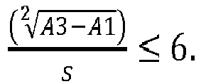
- a further embodiment of the invention provides that the cooling air duct does not exceed a maximum degree of divergence over the first, expanding partial section. Similar to an opening angle definition for diffusers, the increase in the cross-sectional area of the cooling air channel in the first section is expediently related to the length of the flow path in the same, so that this ratio describes the degree of divergence in the first section. For the purposes of the present invention, this ratio is defined as A 3 - A 1 2 s ⁇ 6th
- the size s describes the length of the cooling air channel along its center line in the first section and the previously mentioned sizes A1 and A3, the cross-sectional areas of the cooling air duct at the beginning and respectively to the end of the first section.
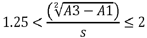
- the ratio thus defined which indicates the degree of divergence in the widening section, is thus at most 6. According to one embodiment of the invention, said ratio is in the range between 1.25 and 6 and in particular in the range between 1.25 and 2: 1 . 25 ⁇ A 3 - A 1 2 s ⁇ Second
- the design of the cooling air duct may be rotationally symmetrical or rotationally asymmetrical with respect to its center line.
- An embodiment of the invention provides that the cooling air channel in the region of the first section has a rotational asymmetry with respect to its center line, the channel expansion thus has a preferred direction.
- the widening of the cooling air duct takes place solely or more strongly in the direction of the pressure side of the blading.
- the divergence in the first section in the direction of the pressure side of the blade is greater than the divergence in the direction of the suction side.
- the bulge of the cooling air duct according to the invention takes place in other words in the direction of the pressure side. As a result, the cooling medium can be accelerated more effectively in the second section in the direction of the suction side.
- a divergence in the first partial section which is greater in the direction of the pressure side of the blade than in the direction of the suction side, is accompanied by the fact that the center line of the cooling air channel in the first partial section has a directional component in the direction of the pressure side of the turbine blade or is inclined in the direction of the pressure side.
- a further embodiment of the invention provides that the cooling air channel in the narrowing section has a deflection angle ⁇ which is smaller than 175 ° and, for example, in the range between 110 ° and 170 °, in particular in the range between 140 ° and 170 °.
- the deflection angle indicates the degree of deflection of the cooling air channel in the second section.
- ⁇ is defined as the angle that exists between the two vectors A 3 A 1 and A 3 A 2 spans. Both vectors describe in each case the direct connecting line between the geometric centers (area centroids) of the cross-sectional areas A3 and A2 or A3 and A1. This definition thus indicates the mean deflection angle of the cooling air channel over both sections, in the direction of the suction side.
- An embodiment of the invention provides that for the acceleration of the cooling medium in the second, narrowing portion with a direction component in the direction of the suction side of the turbine blade of the cooling air duct is shaped such that the center line of the cooling air duct in the narrowing portion a directional component in the direction of the suction side the turbine blade has.
- the first, expanding section is shaped such that the center line of the cooling air duct in the first section has a directional component in the direction of the pressure side of the turbine blade.
- a beginning of a first, expanding subsection should be present if the cooling air channel has a constant cross-sectional course, has a convergent profile or has a divergent profile that is so slight that the cross-sectional area along the Center line of the cooling air duct upstream of the considered beginning of the first section only slightly increased. Only a slight increase in the meaning of the present invention is then present when the degree of divergence of the cooling air duct ⁇ A 2 s is less than 1.25, so 1.25 > ⁇ A 2 s applies. In other words, a slight enlargement occurs when s the cross sectional area by an amount ⁇ A ⁇ (1.25 ⁇ s) increases in an arbitrarily small longitudinal portion of the length. 2
- the considered cooling air duct can have at any point in the turbine blade an embodiment according to the invention for accelerating the cooling medium in the direction of the suction side.
- an embodiment of the invention provides that the turbine blade has a blade root, which is provided and adapted to be arranged in a Schaufelfußfact a turbine disk, wherein the first flared portion and the second narrowing portion are formed in a portion of the cooling air passage which is arranged in the blade root.
- a further embodiment of the invention provides that the cross-sectional area of the second, narrowing section decreases behind the maximum successively and without a jump.
- the invention further relates to a turbine blade ring for a gas turbine with a turbine blade according to claim 1 and a gas turbine, in particular a turbofan engine with such a turbine blade ring.
- the invention provides a method for transporting a cooling medium in a turbine blade of a turbine blade ring, in which the cooling medium is delayed in a first section of the cooling air channel and then in a subsequent second section with a direction component in the direction of the suction side Turbine blade is accelerated.
- the cooling medium is guided in such a way that it first experiences a direction component in the direction of the pressure side in the first section and a direction component in the direction of the suction side in the second section and is thus diverted in the direction of the suction side.
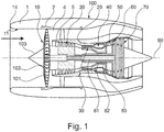
- FIG. 1 1 schematically shows a turbofan engine 100 having a fan stage with a fan 10 as a low-pressure compressor, a medium-pressure compressor 20, a high-pressure compressor 30, a combustion chamber 40, a high-pressure turbine 50, a medium-pressure turbine 60 and a low-pressure turbine 70.
- the medium-pressure compressor 20 and the high-pressure compressor 30 each have a plurality of compressor stages, each comprising a rotor stage and a stator stage.
- the turbofan engine 100 of FIG. 1 further comprises three separate shafts, a low pressure shaft 81 connecting the low pressure turbine 70 to the fan 10, a medium pressure shaft 82 connecting the medium pressure turbine 60 to the intermediate pressure compressor 20, and a high pressure shaft 83 connecting the high pressure turbine 50 to the high pressure compressor 30.
- this is only to be understood as an example.
- the turbofan engine does not have a medium pressure compressor and medium pressure turbine, only a low pressure shaft and a high pressure shaft are present.
- the turbofan engine 100 has an engine nacelle 1, which comprises an inlet lip 14 and, on the inside, forms an engine inlet 11, which supplies incoming air to the fan 10.
- the fan 10 has a plurality of fan blades 101 connected to a fan disk 102.
- the annulus of the fan disk 102 forms the radially inner boundary of the flow path through the fan 10. Radially outside the flow path is limited by a fan housing 2. Upstream of the fan disk 102, a nose cone 103 is disposed.
- the turbofan engine 100 forms a secondary flow channel 4 and a primary flow channel 5.
- the primary flow channel 5 passes through the core engine (gas turbine) comprising the medium pressure compressor 20, the high pressure compressor 30, the combustor 40, the high pressure turbine 50, the medium pressure turbine 60, and the low pressure turbine 70.
- the medium-pressure compressor 20 and the high-pressure compressor 30 are surrounded by a peripheral housing 29, that on the inside forms an annular space surface which defines the primary flow channel 5 radially outward.
- Radially inside, the primary flow channel 5 is bounded by corresponding ring surfaces of the rotors and stators of the respective compressor stages or by the hub or hub connected to the elements of the corresponding drive shaft.
- a primary flow passes through the primary flow passage 5, which is also referred to as the main flow passage.
- the secondary flow channel 4 also referred to as bypass duct or by-pass duct, passes air sucked by the fan 10 past the core engine during operation of the turbofan engine 100.
- the described components have a common axis of rotation 90.
- the axis of rotation 90 defines an axial direction of the turbofan engine.
- a radial direction of the turbofan engine is perpendicular to the axial direction.
- the design of the turbine blades, in particular the turbine blades of the high-pressure turbine 50 is important.
- the principles of the present invention are equally applicable to turbine blades of other turbine stages.
- the turbine blades contemplated by the invention are part of a blade assembly that includes a turbine disk and a turbine blade ring with turbine blades.
- the turbine blades are referred to in this description as turbine blades.
- the turbine disk For attachment of the turbine blades at an equidistant distance on the circumference of the turbine disk, the turbine disk on its periphery on a plurality of Schaufelfuß techniquen, each serving to receive a blade root of a blade. It can be provided that the blade feet are designed as so-called "pine tree feet".
- the Schaufelfuß techniquen are formed in a corresponding manner.
- the Turbine disc has channels that serve to provide cooling air for cooling the turbine blades.
- FIG. 2 shows on the basis of an embodiment, a negative model of a turbine blade.
- the cavities of the turbine blade are shown.
- These form a system 15 of cooling air ducts, which serve to cool the turbine blade.
- the system 15 of cooling air ducts includes two input cooling air ducts 16, 17, both of which extend in the blade root of the turbine blade.
- the input cooling air ducts 16, 17 form a bulge 7, in which the cross-sectional area of the input cooling air ducts 16, 17 has a maximum.
- the one input channel 16 extends as a cooling air channel 161 adjacent to the leading edge of the turbine blade.
- the other input channel 17 forms in the flow direction behind the bulge 7 a cooling air channel with three serpentine portions 171, 172, 173, which extend substantially in the radial direction and are interconnected by curved portions. From the cooling air passages are each cooling air holes 165, 175, which serve to cool the turbine blade.
- the FIG. 2 is merely an example.
- the exact shape and number of cooling air channels and the type of cooling are not important to the present invention. It can be done, for example, a film cooling and / or cooling by convection. Of importance for the present invention is only formed in the input cooling air ducts 16, 17 bulge 7. It is also noted that the cooling air ducts basically have any cross-sectional shape, for example, circular, elliptical or rectangular can be performed.
- the Figures 3 and 4 show a turbine blade 200, which is a system 15 of cooling air ducts according to the FIG. 2 having. This is in the Figures 3 and 4 indicated by a transparent representation of the turbine blade.
- the turbine blade 200 is in the FIG. 3 in a view from the front, ie in a view in the axial direction shown on the blade leading edge.
- the turbine blade 200 is in the FIG. 4 shown in a side view on the print page.
- the turbine blade 200 includes a blade root 21 and an airfoil 22.
- the blade root 21 is intended to be located in a blade root receiver of a turbine blade. He has, for example, a Christmas tree profile 23.
- the airfoil 22 includes a suction side 24, a pressure side 25, a leading edge 26, a trailing edge 27, a blade tip 28.
- the airfoil 22 protrudes into the primary flow channel of the turbofan engine.
- x indicate the axial direction and r the radial direction.
- the circumferential direction ⁇ is perpendicular to x and r.
- the axial direction x may be identical to the machine axis of a gas turbine in which the invention is implemented, but may be different (for example, when the blades are inserted into the blade root receivers at an angle to the machine axis).
- the inlet cooling air ducts 16, 17 and the cooling air ducts 161, 171, 172, 173 extend essentially in the radial direction.
- the in the FIG. 2 shown and in the FIG. 3 Recognizable bulge 7 extends in the direction of the pressure side 25 of the turbine blade 200.
- FIG. 5 shows in an enlarged view in a perspective view obliquely from the front of the blade root 21, in which the input cooling air ducts 16, 17 are formed.
- the illustration ends at a sectional area A, which forms a cross-sectional area of the blade root 21 perpendicular to the radial direction r.
- the shape of the one input cooling air channel 16 is schematically ( FIG. 6 ) and on the other hand by means of an embodiment ( Figures 7-10 ) exemplified.
- the statements apply in a corresponding manner for the further input cooling air duct 17 of the Figures 3-5 , wherein it is not mandatory that both input cooling air ducts 16, 17 have a shape according to the invention.
- the turbine blade 200 does not necessarily have to have multiple input cooling air channels 16, 17. In alternative embodiments of the invention, only one input cooling air channel is provided, which is then designed as described below.
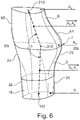
- the FIG. 6 is a three-dimensional representation of an input cooling air duct 16 (hereinafter referred to as cooling air duct 16).
- the cooling air duct 16 comprises a first, expanding section 3, in which the cross-sectional area of the cooling air duct 16 increases in the flow direction of the cooling medium, starting from a cross-sectional area A1 at the beginning of the widening section 3 to a maximum A3.
- the first, widening section 3 is followed by a second, narrowing section 6, in which the cross-sectional area reduces from the maximum cross-sectional area A3 to a cross-sectional area A2 at the end of the narrowing section 6.
- the wall of this subsection is formed toward the pressure side 25 through a wall contour 31 and toward the suction side 24 through a wall contour 32.
- the wall of this subsection is formed towards the pressure side 25 through a wall contour 61 and toward the suction side 24 through a wall contour 62.
- the changing cross sections of the cooling air channel 16 lead to a delay of the flow velocity of the cooling medium in the widening section 3 and to an acceleration of the flow velocity of the cooling medium in the tapered section 6.
- the cooling air passage 16 is further formed in the considered portions 3, 6 so as to accelerate the cooling medium in the second narrowing portion 6 with a directional component toward the suction side of the turbine blade. Due to this acceleration of the cooling medium, an acceleration of the cooling medium due to the Coriolis force is counteracted. In this way, in a considered cross-sectional plane at all wall regions of the cooling air duct, a homogenization of the heat transfer takes place.
- the exact shape is as follows.
- the cross-sectional area A1 is the cross-sectional area at the beginning of the first subregion 3.
- the cross-sectional area of the cooling air channel increases in a rotationally asymmetrical manner with respect to its center line in the direction of the pressure side.
- the geometric course of the cooling air duct 16 is described over its center line, which is the connecting line of all represents geometric centers (ie centroids) of the cross-sectional areas of the cooling air duct.
- a representative of the cooling air flow cross-sectional area of the cooling air channel 16 is defined so that the center line of the cooling air channel 16, the plane of the cross-sectional area always pierces vertically.
- the normal vector of such a cross-sectional area corresponds to the tangent vector to the center line in the geometric center (area centroid) of the respective cross-sectional area.
- the cross-sectional widening can be rotationally symmetrical or alternatively rotationally asymmetric with respect to the center line of the cooling air channel.
- the rotationally asymmetric channel widening which is initially accompanied by a guide of the cooling air channel 16 in the direction of the pressure side, leads to an increase in the structurally realizable deflection angle ⁇ in the second partial region 6.
- the degree of divergence of the expanding cooling air channel 16 should not exceed a maximum degree of divergence. Similar to an opening angle definition for diffusers, the maximum increase in the cross-sectional area of the cooling air channel 16 in the first section 3 is expediently related to the length of the flow path in the same, so that this ratio describes the degree of divergence in the first section 3. For the purposes of the present invention, this maximum ratio is defined as A 3 - A 1 2 s ⁇ 6th
- the size s describes the length of the cooling air duct along its center line in the first section 3 and the previously mentioned sizes A1 and A3, the cross-sectional areas of the cooling air duct 16 at the beginning and respectively to the end of the first section 3.
- the said ratio is according to an embodiment of the invention between 1.25 and 2.
- the cross-sectional area ratio A3 / A1 is, according to one embodiment of the invention, in the range between 1 and 5, for example between 2 and 4.
- the cross-sectional area A3 at the transition between the first partial area 3 and the second partial area 6 represents the maximum cross-sectional area. Starting from this maximum, the cooling-air channel 16 tapers in the second partial area 6.
- the convergence of the cooling air channel in the second subregion 6 is defined by the ratio A3 / A2. It is provided that this ratio is smaller than the ratio A3 / A1, in other words A1 is smaller than A2 and A2 is smaller than A3: A 1 ⁇ A 2 ⁇ A Third
- the shape of the convergence in the second subarea 6 is determined inter alia by the convergence or deflection angle ⁇ .
- This is angle ⁇ is defined as the angle that exists between the two vectors A 3 A 1 and A 3 A 2 spans. Both vectors each describe the direct connecting line between the geometric centers (centroids) 310, 210 and 110 of the cross-sectional areas A3 and A2 or A3 and A1.
- the definition thus indicates the mean deflection angle of the cooling air duct via both sections 3, 6, in the direction of the suction side.
- the deflection angle ⁇ is at most 175 °. It is for example in the range between 110 ° and 170 °, in particular in the range between 140 ° and 170 °.
- cross-sectional area referred to herein is defined by a normal vector corresponding to the tangent vector to the centerline in the geometric center (area centroid) of the cross-sectional area.
- the first, expanding section 3 is shaped such that the vector A 1 A 3 or the center line of the cooling air channel in the first section 3, the at least approximately the vector A 1 A 3 corresponds, due to the bulge 7, which extends in the direction of the pressure side 25, to the cross-sectional area A3 toward a direction component in the direction of the pressure side 25 and does not extend exactly radially.
- FIG. 7 shows an example of an embodiment of a cooling air duct 16, which corresponds to the FIG. 6 is formed and formed in the blade root 21 of a turbine blade 200.
- the FIGS. 8, 9 and 10 show cross sections perpendicular to the radial direction of the blade root 21 in the height of the cross section A2 (FIG. FIG. 8 ), of the section A3 ( FIG. 9 ) and the cross section A1 ( FIG. 10 ).
- the FIG. 7 shows the first divergent section 3 with the wall contours 31, 32, the second convergent wall section 6 with the wall contours 61, 62 and the three cross-sectional areas A1, A3, and A2.
- the bulge 7 extends in the direction of the pressure side 25.
- the cooling air duct 16 in the region of the cross-sectional area A1 approximately circular (rotationally symmetrical with respect to the center line) is formed. Wall areas that extend in the direction of the pressure side or suction side are not provided.
- the cooling air duct 16 in the region of the cross-sectional area A3 no longer circular (but rotationally asymmetric with respect to the center line) is formed. Rather, the wall portions 31, 32 executed as described in FIG FIG. 7 to a greater extent in the circumferential direction (between the pressure side and suction side) than in the axial direction.
- FIG. 8 for the cooling air channel 16 in the region of the cross-sectional area A2 wherein in the illustrated plan view from above of the obliquely extending wall portion 62 can be seen.
- the present invention is not limited in its embodiment to the embodiments described above.
- a bulge according to the invention of a cooling air channel is not formed in the blade root, but rather elsewhere in the cooling air channel, or that a cooling air channel has several such bulges, for example a bulge in the blade root and a further bulge in the further course of the cooling air channel.
Landscapes
- Engineering & Computer Science (AREA)
- Mechanical Engineering (AREA)
- General Engineering & Computer Science (AREA)
- Physics & Mathematics (AREA)
- Fluid Mechanics (AREA)
- Turbine Rotor Nozzle Sealing (AREA)
Abstract
Description
- Die Erfindung betrifft eine Turbinenschaufel eines Turbinen-Laufschaufelkranzes gemäß dem Oberbegriff des Patentanspruchs 1 und ein Verfahren zum Transportieren eines Kühlmediums in einer Turbinenschaufel eines Turbinen-Laufschaufelkranzes.
- Es ist bekannt, die Turbinenschaufeln einer Gasturbine zu kühlen. Zur Kühlung der Turbinenschaufeln weisen diese interne Kühlluftkanäle auf, die mit Luft beaufschlagt werden. Dabei wirkt im Betrieb der Gasturbine auf das Kühlmedium die Corioliskraft. Da eine Turbinenschaufel eine Drehrichtung in Richtung der Saugseite aufweist, wird das Kühlmedium durch die Corioliskraft in Richtung der Druckseite abgelenkt. Dies führt dazu, dass das Kühlmedium unterschiedliche Wandbereiche des Kühlluftkanals in unterschiedlichem Maße kühlt. Die damit einhergehende Inhomogenität der Kühlung reduziert deren Effektivität und kann thermische Spannungen im Material induzieren.
- Der vorliegenden Erfindung liegt die Aufgabe zu Grunde, eine Turbinenschaufel und ein Verfahren zum Transportieren eines Kühlmediums in einer Turbinenschaufel bereitzustellen, die eine verbesserte Kühlung der Turbinenschaufel ermöglichen.
- Diese Aufgabe wird erfindungsgemäß durch eine Turbinenschaufel mit den Merkmalen des Anspruchs 1 und ein Verfahren mit den Merkmalen des Anspruchs 15 gelöst. Ausgestaltungen der Erfindung sind in den abhängigen Ansprüchen angegeben.
- Danach sieht die Erfindung in einem ersten Erfindungsaspekt vor, dass ein Kühlluftkanal einer Turbinenschaufel in mindestens einem Abschnitt einen Verlauf derart aufweist, dass seine Querschnittsfläche sich in Strömungsrichtung des Kühlmediums in einem ersten, sich erweiternden Teilabschnitt bis zu einem Maximum vergrößert, sich anschließend in einem zweiten, sich verengenden Teilabschnitt hinter dem Maximum wieder reduziert und dabei das Kühlmedium in dem zweiten, sich verengenden Teilabschnitt mit einer Richtungskomponente in Richtung der Saugseite der Turbinenschaufel beschleunigt wird. Dabei ist vorgesehen, dass der Kühlluftkanal im Bereich des Maximums eine Ausbuchtung in Richtung der Druckseite bildet, wobei das Kühlmedium in dem ersten Teilabschnitt in Richtung der Druckseite und in dem zweiten Teilabschnitt in Richtung der Saugseite abgelenkt wird.
- Die vorliegende Erfindung beruht auf dem Gedanken, das Kühlmedium in dem ersten, sich erweiternden Teilabschnitt erst zu verzögern und anschließend in dem zweiten, sich verengenden Teilabschnitt zu beschleunigen und dabei den Kühlluftkanal derart zu formen, dass das Kühlmedium bei der Beschleunigung, die es im sich verengenden zweiten Teilabschnitt erfährt, in Richtung der Saugseite der Turbinenscheibe abgelenkt wird. Hierdurch wird die Wirkung der Corioliskraft, die das Kühlmedium während der Rotation der Turbinenschaufel in Richtung der Druckseite beschleunigt, zumindest teilweise kompensiert. Das Kühlmedium kann dadurch verbessert im Kühlluftkanal strömen, wobei gleichwohl der Wärmeübergang über alle Wände des Kühlluftkanals vergleichmäßigt wird. Als Ergebnis liegt eine homogenere Temperaturverteilung und verbesserte Kühlung der Turbinenschaufel vor.
- Durch die homogenere Temperaturverteilung werden darüber hinaus thermisch induzierte Spannungen im Material der Turbinenscheibe reduziert.
- Zur Beschleunigung des Kühlmediums in dem zweiten, sich verengenden Teilabschnitt mit einer Richtungskomponente in Richtung der Saugseite der Turbinenschaufel ist der Kühlluftkanal dabei derart geformt, dass er im Bereich des Maximums eine Ausbuchtung in Richtung der Druckseite bildet, d.h. nur in Richtung der Druckseite oder stärker in Richtung der Druckseite als in Richtung der Saugseite ausgebuchtet ist. Diese Formgebung des ersten Teilabschnitts bewirkt, dass das Kühlmedium im ersten Teilabschnitt in Richtung der Druckseite geführt und dadurch im zweiten Teilabschnitt effektiv in Richtung der Saugseite beschleunigt bzw. abgelenkt werden kann.
- Die Erfindung führt zu einer Ausbuchtung des Kühlluftkanals, welche durch die sich erweiternden und verengenden Teilabschnitte entsteht.
- Die vorliegende Erfindung wird bezogen auf ein zylindrisches Koordinatensystem beschrieben, das die Koordinaten x, r und ϕ aufweist. Dabei gibt x die axiale Richtung, r die radiale Richtung und ϕ den Winkel in Umfangsrichtung an. Die axiale Richtung ist in der Regel identisch mit der Maschinenachse einer Gasturbine bzw. eines TurbofanTriebwerks, in der die Erfindung realisiert ist. Von der x-Achse ausgehend zeigt die radiale Richtung radial nach außen. Begriffe wie "vor", "hinter", "vordere" und "hintere" beziehen sich auf die axiale Richtung bzw. die Strömungsrichtung in der Gasturbine oder des hier beschriebenen Kühlluftkanals. Die Bezeichnung "vor" bedeutet somit "stromaufwärts" und die Bezeichnung "hinter" bedeutet "stromabwärts". Begriffe wie "äußere" oder "innere" beziehen sich auf die radiale Richtung.
- Der geometrische Verlauf eines Kühlluftkanals wird hierin zweckmäßigerweise über seine Mittellinie beschrieben, welche die Verbindungslinie aller geometrischen Mittelpunkte (Flächenschwerpunkte) der Querschnittsflächen des Kühlluftkanals darstellt. Eine für die Strömung repräsentative Querschnittsfläche des Kühlluftkanals ist dabei so definiert, dass die Mittellinie des Kühlluftkanals die Ebene der Querschnittsfläche stets senkrecht durchstößt. Mit anderen Worten entspricht also der Normalvektor einer solchen Querschnittsfläche dem Tangentenvektor an die Mittellinie im geometrischen Mittelpunkt (Flächenschwerpunkt) der jeweiligen Querschnittsfläche.
- Der Kühlluftkanal weist am Anfang des sich erweiternden Teilabschnitts eine erste Querschnittsfläche A1, am Ende des sich verengenden Teilabschnitts eine zweite Querschnittsfläche A2 und am Maximum eine dritte Querschnittsfläche A3 auf.
- Für das Verhältnis von erster Querschnittsfläche A1 und dritter Querschnittsfläche A3 gilt gemäß einer Ausgestaltung der Erfindung: 1 < A3/A1 ≤ 5. Das Verhältnis von maximaler Querschnittsfläche zur Querschnittsfläche am Anfang des ersten Teilabschnitts soll gemäß dieser Ausgestaltung der Erfindung somit kleinergleich 5 sein. Die Querschnittsfläche soll sich im ersten Teilbereich um maximal den Faktor 5 vergrößern, um eine zu starke Verzögerung der Strömung des Kühlluftmediums zu vermeiden.
- Eine weitere Ausgestaltung der Erfindung sieht vor, dass für das Verhältnis von erster Querschnittsfläche A1, zweiter Querschnittsfläche A2 und dritter Querschnittsfläche A3 gilt: A1 < A2 < A3. Mathematisch kann dies auch durch die Beziehung ausgedrückt werden: A3/A1 > A3/A2. Die (zweite) Querschnittsfläche am Ende des zweiten, sich verjüngenden Teilbereichs ist also größer als die (erste) Querschnittsfläche am Anfang des ersten, sich erweiternden Teilbereichs. Beide diese Querschnitte sind kleiner als der maximale Querschnitt am Übergang vom ersten Teilbereich zum zweiten Teilbereich. Dabei ist zu beachten, dass das Kühlmedium im zweiten Teilabschnitt zusätzlich eine Beschleunigungs- und Richtungskomponente in Richtung der Saugseite der Turbinenschaufel erfährt.
- Eine weitere Ausgestaltung der Erfindung sieht vor, dass der Kühlluftkanal über den ersten, sich erweiternden Teilabschnitt einen maximalen Grad an Divergenz nicht überschreitet. Ähnlich einer Öffnungswinkeldefinition für Diffusoren wird hier zweckmäßigerweise der Zuwachs der Querschnittsfläche des Kühlluftkanals im ersten Teilabschnitt auf die Länge des Strömungsweges in Selbigen bezogen, so dass dieses Verhältnis den Grad an Divergenz im ersten Teilabschnitt beschreibt. Dabei ist im Sinne der vorliegenden Erfindung dieses Verhältnis definiert als

- Hierin beschreibt die Größe s die Länge des Kühlluftkanals entlang seiner Mittellinie im ersten Teilabschnitt und die bereits zuvor genannten Größen A1 und A3 die Querschnittsflächen des Kühlluftkanals zu Beginn und respektive zum Ende des ersten Teilabschnitts.
- Das so definierte Verhältnis, das den Grad an Divergenz im sich erweiternden Teilabschnitt angibt, liegt somit bei maximal 6. Gemäß einer Ausgestaltung der Erfindung liegt das genannte Verhältnis im Bereich zwischen 1,25 und 6 und insbesondere im Bereich zwischen 1,25 und 2:

- Die Ausgestaltung des Kühlluftkanals kann rotationssymmetrisch oder rotations-asymmetrisch bezüglich seiner Mittellinie sein.
- Eine Ausgestaltung der Erfindung sieht vor, dass der Kühlluftkanal im Bereich des ersten Teilabschnittes eine Rotations-Asymmetrie bezüglich seiner Mittellinie aufweist, die Kanalaufweitung also eine Vorzugsrichtung hat.
- Weiter kann vorgesehen sein, dass die Aufweitung des Kühlluftkanals alleinig oder stärker in Richtung der Druckseite der Beschaufelung erfolgt. Somit ist bei dieser Erfindungsvariante die Divergenz im ersten Teilabschnitt in Richtung der Druckseite der Schaufel größer als die Divergenz in Richtung der Saugseite. Die erfindungsgemäße Ausbuchtung des Kühlluftkanals erfolgt mit anderen Worten in Richtung der Druckseite. Hierdurch kann das Kühlmedium in zweiten Teilabschnitt effektiver in Richtung der Saugseite beschleunigt werden. Eine Divergenz im ersten Teilabschnitt, die in Richtung der Druckseite der Schaufel größer als in Richtung der Saugseite, geht damit einher, dass die Mittellinie des Kühlluftkanals im ersten Teilabschnitt eine Richtungskomponente in Richtung der Druckseite der Turbinenschaufel aufweist bzw. in Richtung der Druckseite geneigt ist.
- Eine weitere Ausgestaltung der Erfindung sieht vor, dass der Kühlluftkanal im sich verengenden Teilabschnitt einen Umlenkwinkel δ aufweist, der kleiner als 175° ist und beispielsweise im Bereich zwischen 110° und 170°, insbesondere im Bereich zwischen 140° und 170° liegt. Der Umlenkwinkel gibt dabei den Grad an Umlenkung des Kühlluftkanals im zweiten Teilabschnitt an. Genauer ist δ als jener Winkel definiert, der sich zwischen den beiden Vektoren
A3A1 undA3A2 aufspannt. Beide Vektoren beschreiben jeweils die direkt Verbindungslinie zwischen den geometrischen Mittelpunkten (Flächenschwerpunkten) der Querschnittsflächen A3 und A2 bzw. A3 und A1. Diese Definition gibt somit den mittleren Umlenkwinkel des Kühlluftkanals über beide Teilabschnitte, in Richtung der Saugseite an. - Eine Ausgestaltung der Erfindung sieht vor, dass zur Beschleunigung des Kühlmediums in dem zweiten, sich verengenden Teilabschnitt mit einer Richtungskomponente in Richtung der Saugseite der Turbinenschaufel der Kühlluftkanal derart geformt ist, dass die Mittellinie des Kühlluftkanals in dem sich verengenden Teilabschnitt eine Richtungskomponente in Richtung der Saugseite der Turbinenschaufel aufweist.
- Dagegen ist der erste, sich erweiternde Teilabschnitt gemäß einer Ausgestaltung der Erfindung derart geformt, dass die Mittellinie des Kühlluftkanals im ersten Teilabschnitt eine Richtungskomponente in Richtung der Druckseite der Turbinenschaufel aufweist.
- Ein Anfang eines ersten, sich erweiternden Teilabschnitts soll im Sinne der vorliegenden Erfindung dann vorliegen, wenn der Kühlluftkanal stromaufwärts eines solchen Anfangs einen konstanten Querschnittsflächenverlauf aufweist, einen konvergenten Verlauf aufweist oder einen divergenten Verlauf aufweist, der so geringfügig ist, dass sich die Querschnittsfläche entlang der Mittellinie des Kühlluftkanals stromaufwärts des betrachteten Anfangs des ersten Teilabschnitts nur geringfügig vergrößert. Eine nur geringfügige Vergrößerung im Sinne der vorliegenden Erfindung liegt dabei dann vor, wenn der Grad der Divergenz des Kühlluftkanals


- Der betrachtete Kühlluftkanal kann grundsätzlich an beliebiger Stelle in der Turbinenschaufel eine erfindungsgemäße Ausgestaltung zur Beschleunigung des Kühlmediums in Richtung der Saugseite aufweisen. In besonders effektiver Weise ist eine solche Ausgestaltung in einem Abschnitt des Kühlluftkanals vorgesehen, in dem das Kühlmedium sich primär in radialer Richtung bewegt und bevor sich der Kühlluftkanal in eine Vielzahl kleinerer Kühlkanäle verzweigt. Dementsprechend sieht eine Ausgestaltung der Erfindung vor, dass die Turbinenschaufel einen Schaufelfuß aufweist, der dazu vorgesehen und geeignet ist, in einer Schaufelfußaufnahme einer Turbinenscheibe angeordnet zu sein, wobei der erste sich erweiternde Teilabschnitt und der zweite sich verengenden Teilabschnitt in einem Abschnitt des Kühlluftkanals ausgebildet sind, der im Schaufelfuß angeordnet ist.
- Eine weitere Ausgestaltung der Erfindung sieht vor, dass die Querschnittsfläche des zweiten, sich verengenden Teilabschnitts hinter dem Maximum sukzessive und ohne einen Sprung abnimmt.
- Die Erfindung betrifft des Weiteren einen Turbinen-Laufschaufelkranz für eine Gasturbine mit einer Turbinenschaufel gemäß Anspruch 1 und eine Gasturbine, insbesondere ein Turbofantriebwerk mit einem solchen Turbinen-Laufschaufelkranz.
- Die Erfindung sieht in einem zweiten Erfindungsaspekt ein Verfahren zum Transportieren eines Kühlmediums in einer Turbinenschaufel eines Turbinen-Laufschaufelkranzes vor, bei dem das Kühlmedium in einem ersten Teilabschnitt des Kühlluftkanals verzögert und anschließend in einem sich daran anschließenden zweiten Teilabschnitt mit einer Richtungskomponente in Richtung der Saugseite der Turbinenschaufel beschleunigt wird.
- Dabei wird das Kühlmedium derart geführt, dass es in dem ersten Teilabschnitt zunächst eine Richtungskomponente in Richtung der Druckseite und im zweiten Teilabschnitt eine Richtungskomponente in Richtung der Saugseite erfährt und somit in Richtung der Saugseite umgeleitet wird. Durch das Führen des Kühlmediums zunächst in Richtung der Druckseite wird eine Umleitung in Richtung der Saugseite im zweiten Teilbereich erleichtert.
- Die Erfindung wird nachfolgend unter Bezugnahme auf die Figuren der Zeichnung anhand mehrerer Ausführungsbeispiele näher erläutert. Es zeigen:
- Figur 1
- eine vereinfachte schematische Schnittdarstellung eines Turbofantriebwerks, in dem die vorliegende Erfindung realisierbar ist;
- Figur 2
- ein Negativmodell einer Turbinenschaufel unter Darstellung der in der Turbinenschaufel realisierten Kühlluftkanäle;
- Figur 3
- die Außenkonturen einer Turbinenschaufel in einer Ansicht von vorne unter zusätzlicher Darstellung der Kühlluftkanäle gemäß der
Figur 2 ; - Figur 4
- die Turbinenschaufel der
Figur 3 in einer Seitenansicht auf die Druckseite; - Figur 5
- den Schaufelfuß der Turbinenschaufel der
Figuren 3 und4 in einer Ansicht schräg von vorne; - Figur 6
- schematisch den Verlauf eines im Schaufelfuß ausgebildeten Kühlluftkanals, dessen Querschnittsfläche sich in Strömungsrichtung des Kühlmediums in einem ersten Teilabschnitt vergrößert und anschließend in einem zweiten Teilabschnitt reduziert, wobei das Kühlmedium in Richtung der Saugseite der Turbinenschaufel beschleunigt wird;
- Figur 7
- eine Querschnittsansicht eines Schaufelfußes gemäß der
Figur 5 in einer Ebene senkrecht zur axialen Richtung, wobei der Schaufelfuß einen Kühlluftkanals ausbildet, dessen Querschnittsfläche sich entsprechend derFigur 6 in Strömungsrichtung des Kühlmediums in einem ersten Teilabschnitt vergrößert und in einem zweiten Teilabschnitt reduziert; - Figur 8
- eine Querschnittsansicht des Schaufelfußes der
Figur 7 in einer Ebene senkrecht zur radialen Richtung in einer radialen Höhe, die dem Ende des zweiten Teilabschnitts entspricht; - Figur 9
- eine Querschnittsansicht des Schaufelfußes der
Figur 7 in einer Ebene senkrecht zur radialen Richtung in einer radialen Höhe, die dem Ende des ersten Teilabschnitts entspricht; und - Figur 10
- eine Querschnittsansicht des Schaufelfußes der
Figur 7 in einer Ebene senkrecht zur radialen Richtung in einer radialen Höhe, die dem Anfang des ersten Teilabschnitts entspricht. - Die
Figur 1 zeigt schematisch ein Turbofantriebwerk 100, das eine Fanstufe mit einem Fan 10 als Niederdruckverdichter, einen Mitteldruckverdichter 20, einen Hochdruckverdichter 30, eine Brennkammer 40, eine Hochdruckturbine 50, eine Mitteldruckturbine 60 und eine Niederdruckturbine 70 aufweist. - Der Mitteldruckverdichter 20 und der Hochdruckverdichter 30 weisen jeweils eine Mehrzahl von Verdichterstufen auf, die jeweils eine Rotorstufe und eine Statorstufe umfassen. Das Turbofantriebwerk 100 der
Figur 1 weist des Weiteren drei separate Wellen auf, eine Niederdruckwelle 81, die die Niederdruckturbine 70 mit dem Fan 10 verbindet, eine Mitteldruckwelle 82, die die Mitteldruckturbine 60 mit dem Mitteldruckverdichter 20 verbindet und eine Hochdruckwelle 83, die die Hochdruckturbine 50 mit dem Hochdruckverdichter 30 verbindet. Dies ist jedoch lediglich beispielhaft zu verstehen. Wenn das Turbofantriebwerk beispielsweise keinen Mitteldruckverdichter und keine Mitteldruckturbine besitzt, sind nur eine Niederdruckwelle und eine Hochdruckwelle vorhanden. - Das Turbofantriebwerk 100 weist eine Triebwerksgondel 1 auf, die eine Einlauflippe 14 umfasst und innenseitig einen Triebwerkseinlauf 11 ausbildet, der einströmende Luft dem Fan 10 zuführt. Der Fan 10 weist eine Mehrzahl von Fan-Schaufeln 101 auf, die mit einer Fan-Scheibe 102 verbunden sind. Der Annulus der Fan-Scheibe 102 bildet dabei die radial innere Begrenzung des Strömungspfads durch den Fan 10. Radial außen wird der Strömungspfad durch ein Fangehäuse 2 begrenzt. Stromaufwärts der Fan-Scheibe 102 ist ein Nasenkonus 103 angeordnet.
- Hinter dem Fan 10 bildet das Turbofantriebwerk 100 einen Sekundärstromkanal 4 und einen Primärstromkanal 5 aus. Der Primärstromkanal 5 führt durch das Kerntriebwerk (Gasturbine), das den Mitteldruckverdichter 20, den Hochdruckverdichter 30, die Brennkammer 40, die Hochdruckturbine 50, die Mitteldruckturbine 60 und die Niederdruckturbine 70 umfasst. Dabei sind der Mitteldruckverdichter 20 und der Hochdruckverdichter 30 von einem Umfangsgehäuse 29 umgeben, dass innenseitig eine Ringraumfläche bildet, die den Primärstromkanal 5 radial außen begrenzt. Radial innen ist der Primärstromkanal 5 durch entsprechende Kranzoberflächen der Rotoren und Statoren der jeweiligen Verdichterstufen bzw. durch die Nabe oder mit der Nabe verbundene Elemente der entsprechenden Antriebswelle begrenzt.
- Im Betrieb des Turbofantriebwerks 100 durchströmt ein Primärstrom den Primärstromkanal 5, der auch als Hauptströmungskanal bezeichnet wird. Der Sekundärstromkanal 4, auch als Nebenstromkanal oder Bypass-Kanal bezeichnet leitet im Betrieb des Turbofantriebwerks 100 vom Fan 10 angesaugte Luft am Kerntriebwerk vorbei.
- Die beschriebenen Komponenten besitzen eine gemeinsame Rotations- bzw. Maschinenachse 90. Die Rotationsachse 90 definiert eine axiale Richtung des Turbofantriebwerks. Eine radiale Richtung des Turbofantriebwerks verläuft senkrecht zur axialen Richtung.
- Im Kontext der vorliegenden Erfindung ist die Ausgestaltung der Turbinenschaufeln, insbesondere der Turbinenschaufeln der Hochdruckturbine 50 von Bedeutung. Die Prinzipien der vorliegenden Erfindung sind jedoch ebenso auf Turbinenschaufeln anderer Turbinenstufen anwendbar.
- Die im Rahmen der Erfindung betrachteten Turbinenschaufeln sind Bestandteil einer Laufschaufelanordnung, die eine Turbinenscheibe und einen Turbinen-Laufschaufelkranz mit Turbinen-Laufschaufeln umfasst. Die Turbinen-Laufschaufeln werden im Rahmen dieser Beschreibung als Turbinenschaufeln bezeichnet. Zur Befestigung der Turbinenschaufeln in äquidistantem Abstand am Umfang der Turbinenscheibe weist die Turbinenscheibe an ihrem Umfang eine Mehrzahl von Schaufelfußaufnahmen auf, die jeweils dazu dienen, einen Schaufelfuß einer Laufschaufel aufzunehmen. Dabei kann vorgesehen sein, dass die Schaufelfüße als sogenannte "Tannenbaumfüße" ausgebildet sind. Die Schaufelfußaufnahmen sind in entsprechender Weise ausgebildet. Die Turbinenscheibe weist Kanäle auf, die dazu dienen, Kühlluft zur Kühlung der Turbinenschaufeln bereitzustellen.
- Die
Figur 2 zeigt anhand eines Ausführungsbeispiels ein Negativmodell einer Turbinenschaufel. Im Negativmodell sind die Aushöhlungen der Turbinenschaufel dargestellt. Diese bilden ein System 15 von Kühlluftkanälen, die der Kühlung der Turbinenschaufel dienen. Im dargestellten Ausführungsbeispiel umfasst das System 15 von Kühlluftkanälen zwei Eingangs-Kühlluftkanäle 16, 17, die sich beide im Schaufelfuß der Turbinenschaufel erstrecken. Wie noch im Einzelnen erläutert wird, bilden die Eingangs-Kühlluftkanäle 16, 17 eine Ausbuchtung 7 aus, in der die Querschnittsfläche der Eingangs-Kühlluftkanäle 16, 17 ein Maximum aufweist. - In Strömungsrichtung hinter der Ausbuchtung 7 erstreckt sich der eine Eingangskanal 16 als Kühlluftkanal 161 benachbart der Vorderkante der Turbinenschaufel. Der andere Eingangskanal 17 bildet in Strömungsrichtung hinter der Ausbuchtung 7 einen Kühlluftkanal mit drei serpentinenartigen Abschnitten 171, 172, 173 aus, die im Wesentlichen in radialer Richtung verlaufen und durch gekrümmte Bereiche miteinander verbunden sind. Von den Kühlluftkanälen gehen jeweils Kühlluftbohrungen 165, 175 aus, die der Kühlung der Turbinenschaufel dienen.
- Weiter ist in der
Figur 2 ein in der zugehörigen Turbinenscheibe ausgebildeter Kanal 18 zu erkennen, über den Kühlluft zugeführt wird. Zwischen der Turbinenscheibe und der Turbinenschaufel entweicht Kühlluft in einem sich in axialer Richtung erstreckenden Spalt 19. - Die
Figur 2 ist lediglich beispielhaft zu verstehen. Die genaue Form und Anzahl der Kühlluftkanäle und die Art der Kühlung sind für die vorliegende Erfindung nicht von Bedeutung. Es kann beispielsweise eine Filmkühlung und/oder eine Kühlung über Konvektion erfolgen. Von Bedeutung für die vorliegende Erfindung ist lediglich die in den Eingangs-Kühlluftkanälen 16, 17 ausgebildete Ausbuchtung 7. Auch wird darauf hingewiesen, dass die Kühlluftkanäle grundsätzlich eine beliebige Querschnittform aufweisen, beispielsweise kreisförmig, elliptisch oder rechteckig ausgeführt sein können. - Die
Figuren 3 und4 zeigen eine Turbinenschaufel 200, die ein System 15 von Kühlluftkanälen entsprechend derFigur 2 aufweist. Dies ist in denFiguren 3 und4 durch eine transparente Darstellung der Turbinenschaufel angedeutet. Die Turbinenschaufel 200 ist in derFigur 3 in einer Ansicht von vorne, d. h. in einer Ansicht in axialer Richtung auf die Schaufelvorderkante dargestellt. Die Turbinenschaufel 200 ist in derFigur 4 in einer Seitenansicht auf die Druckseite dargestellt. Die Turbinenschaufel 200 umfasst einen Schaufelfuß 21 und ein Schaufelblatt 22. Der Schaufelfuß 21 ist dafür vorgesehen, in einer Schaufelfußaufnahme einer Turbinenschaufel angeordnet zu sein. Er weist beispielsweise ein Tannenbaumprofil 23 auf. Das Schaufelblatt 22 umfasst eine Saugseite 24, eine Druckseite 25, eine Vorderkante 26, eine Hinterkante 27, eine Blattspitze 28. Das Schaufelblatt 22 ragt in den Primärstromkanal des Turbofantriebwerks. - In den
Figuren 3 und4 geben x die axiale Richtung und r die radiale Richtung an. In einem zylindrisches Koordinatensystem verläuft die Umfangsrichtung ϕ senkrecht zu x und r. Die axiale Richtung x kann identisch mit der Maschinenachse einer Gasturbine, in der die Erfindung realisiert ist, sein, kann hiervon jedoch auch abweichen (beispielsweise wenn die Laufschaufeln unter einem Winkel zur Maschinenachse in die Schaufelfußaufnahmen gesteckt sind). - Die Eingangs-Kühlluftkanäle 16, 17 sowie die Kühlluftkanäle 161, 171, 172, 173 erstrecken sich im Wesentlichen in radialer Richtung. Die in der
Figur 2 dargestellte und in derFigur 3 erkennbare Ausbuchtung 7 erstreckt sich in Richtung der Druckseite 25 der Turbinenschaufel 200. - Die
Figur 5 zeigt in vergrößerter Darstellung in einer perspektivischen Ansicht schräg von vorne den Schaufelfuß 21, in dem die Eingangs-Kühlluftkanäle 16, 17 ausgebildet sind. Die Darstellung endet an einer Schnittfläche A, die eine Querschnittsfläche des Schaufelfußes 21 senkrecht zur radialen Richtung r bildet. - In den
Figuren 6-10 wird die Formgebung des einen Eingangs-Kühlluftkanals 16 zum einen schematisch (Figur 6 ) und zum anderen anhand eines Ausführungsbeispiels (Figuren 7-10 ) beispielhaft erläutert. Die Ausführungen gelten in entsprechender Weise für den weiteren Eingangs-Kühlluftkanal 17 derFiguren 3-5 , wobei es nicht zwingend ist, dass beide Eingangs-Kühlluftkanäle 16, 17 eine erfindungsgemäße Formgebung aufweisen. Auch wird darauf hingewiesen, dass die Turbinenschaufel 200 nicht notwendigerweise mehrere Eingangs-Kühlluftkanäle 16, 17 aufweisen muss. In alternativen Ausgestaltungen der Erfindung ist lediglich ein Eingangs-Kühlluftkanal vorgesehen, der dann wie nachfolgend beschrieben ausgebildet ist. - Die
Figur 6 ist eine dreidimesionale Darstellung eines Eingangs-Kühlluftkanals 16 (nachfolgend als Kühlluftkanal 16 bezeichnet). Der Kühlluftkanal 16 umfasst einen ersten, sich erweiternden Teilabschnitt 3, in dem sich die Querschnittsfläche des Kühlluftkanal 16 in Strömungsrichtung des Kühlmediums ausgehend von einer Querschnittsfläche A1 am Anfang des sich erweiternden Teilabschnitts 3 bis zu einem Maximum A3 vergrößert. An den ersten, sich erweiternden Teilabschnitt 3 schließt sich ein zweiter, sich verengender Teilabschnitt 6 an, in dem die Querschnittsfläche sich von der maximalen Querschnittsfläche A3 zu einer Querschnittsfläche A2 am Ende des sich verengenden Teilabschnitts 6 reduziert. Im ersten Teilabschnitt 3 wird die Wand dieses Teilabschnitts zur Druckseite 25 hin durch eine Wandkontur 31 und zur Saugseite 24 hin durch eine Wandkontur 32 gebildet. Im zweiten Teilabschnitt 6 wird die Wand dieses Teilabschnitts zur Druckseite 25 hin durch eine Wandkontur 61 und zur Saugseite 24 hin durch eine Wandkontur 62 gebildet. - Die sich verändernden Querschnitte des Kühlluftkanals 16 führen zu einer Verzögerung der Strömungsgeschwindigkeit des Kühlmediums im sich erweiternden Teilabschnitt 3 und zu einer Beschleunigung der Strömungsgeschwindigkeit des Kühlmediums im sich verjüngenden Teilabschnitt 6.
- Der Kühlluftkanal 16 ist in den betrachteten Abschnitten 3, 6 des Weiteren derart geformt, dass das Kühlmedium in dem zweiten, sich verengenden Teilabschnitt 6 mit einer Richtungskomponente in Richtung der Saugseite der Turbinenschaufel beschleunigt wird. Durch diese Beschleunigung des Kühlmediums wird einer Beschleunigung des Kühlmediums aufgrund der Corioliskraft entgegengewirkt. Auf diese Weise erfolgt in einer betrachteten Querschnittsebene an allen Wandbereichen des Kühlluftkanals eine Homogenisierung des Wärmeübergangs.
- Für eine Beschleunigung des Kühlmediums in Richtung der Saugseite bildet der Kühlluftkanal 16 zur Druckseite hin die Ausbuchtung 7 aus, wobei das Kühlmediums in dem ersten Teilbereich 3 in Richtung der Druckseite und in dem zweiten Teilbereich 6 in Richtung der Saugseite abgelenkt wird.
- Die genaue Formgebung ist wie folgt. Die Querschnittsfläche A1 ist die Querschnittsfläche am Anfang des ersten Teilbereichs 3. Hiervon ausgehend vergrößert sich die Querschnittsfläche des Kühlluftkanals rotation-asymmetrisch bezüglich seiner Mittellinie in Richtung der Druckseite. Der geometrische Verlauf des Kühlluftkanals 16 wird dabei über seine Mittellinie beschrieben, welche die Verbindungslinie aller geometrischen Mittelpunkte (d.h. Flächenschwerpunkte) der Querschnittsflächen des Kühlluftkanals darstellt. Eine für die Kühlluftströmung repräsentative Querschnittsfläche des Kühlluftkanals 16 ist dabei so definiert, dass die Mittellinie des Kühlluftkanals 16 die Ebene der Querschnittsfläche stets senkrecht durchstößt. Mit anderen Worten entspricht also der Normalvektor einer solchen Querschnittsfläche dem Tangentenvektor an die Mittellinie im geometrischen Mittelpunkt (Flächenschwerpunkt) der jeweiligen Querschnittsfläche.
- Dabei ist zu beachten, dass die Querschnittserweiterung rotations-symmetrisch oder alternativ rotations-asymmetrisch bezüglich der Mittellinie des Kühlluftkanals erfolgen kann. Im vorliegenden Beispiel führt die rotations-asymmetrische Kanalaufweitung, die mit einer Führung des Kühlluftkanals 16 zunächst in Richtung der Druckseite einhergeht, zu einer Vergrößerung des baulich realisierbaren Umlenkwinkels δ im zweiten Teilbereich 6.
- Der Grad der Divergenz des sich erweiternden Kühlluftkanals 16 sollte einen maximalen Grad an Divergenz nicht überschreitet. Ähnlich einer Öffnungswinkeldefinition für Diffusoren wird hier zweckmäßigerweise der maximale Zuwachs der Querschnittsfläche des Kühlluftkanals 16 im ersten Teilabschnitt 3 auf die Länge des Strömungsweges in Selbigen bezogen, so dass dieses Verhältnis den Grad an Divergenz im ersten Teilabschnitt 3 beschreibt. Dabei ist im Sinne der vorliegenden Erfindung diese maximale Verhältnis definiert als

- Hierin beschreibt die Größe s die Länge des Kühlluftkanals entlang seiner Mittellinie im ersten Teilabschnitt 3 und die bereits zuvor genannten Größen A1 und A3 die Querschnittsflächen des Kühlluftkanals 16 zu Beginn und respektive zum Ende des ersten Teilabschnitts 3. Das genannte Verhältnis liegt gemäß einer Ausgestaltung der Erfindung zwischen 1,25 und 2.
- Das Querschnittsflächenverhältnis A3/A1 liegt gemäß einer Ausgestaltung der Erfindung im Bereich zwischen 1 und 5, beispielsweise zwischen 2 und 4.
- Die Querschnittsfläche A3 am Übergang zwischen dem ersten Teilbereich 3 und dem zweiten Teilbereich 6 stellt die maximale Querschnittsfläche dar. Ausgehend von diesem Maximum verjüngt sich der Kühlluftkanal 16 in dem zweiten Teilbereich 6.
- Die Konvergenz des Kühlluftkanals im zweiten Teilbereich 6 wird durch das Verhältnis A3/A2 definiert. Dabei ist vorgesehen, dass dieses Verhältnis kleiner ist als das Verhältnis A3/A1, mit anderen Worten A1 kleiner als A2 und A2 kleiner als A3 ist:

- Die Form der Konvergenz im zweiten Teilbereich 6 wird unter anderem durch den Konvergenz- oder Umlenkwinkel δ bestimmt. Dieser ist Winkel δ ist definiert als jener Winkel, der sich zwischen den beiden Vektoren
A3A1 undA3A2 aufspannt. Beide Vektoren beschreiben jeweils die direkt Verbindungslinie zwischen den geometrischen Mittelpunkten (Flächenschwerpunkten) 310, 210 und 110 der Querschnittsflächen A3 und A2 bzw. A3 und A1. Die Definition gibt somit den mittleren Umlenkwinkel des Kühlluftkanals über beide Teilabschnitte 3, 6, in Richtung der Saugseite an. - Der Umlenkwinkel δ liegt bei maximal 175°. Er liegt beispielsweise im Bereich zwischen 110° und 170°, insbesondere im Bereich zwischen 140° und 170°.
- Es wird darauf hingewiesen, dass die hier genannte Querschnittsfläche durch einen Normalenvektor definiert wird, der dem Tangentenvektor an die Mittellinie im geometrischen Mittelpunkt (Flächenschwerpunkt) der Querschnittsfläche entspricht.
- Es wird weiter darauf hingewiesen, dass der erste, sich erweiternde Teilabschnitt 3 derart geformt ist, dass der Vektor
A1A3 bzw. die Mittellinie des Kühlluftkanals im ersten Teilabschnitt 3, die zumindest näherungsweise dem VektorA1A3 entspricht, aufgrund der Ausbuchtung 7, die sich in Richtung der Druckseite 25 erstreckt, zur Querschnittsfläche A3 hin eine Richtungskomponente in Richtung der Druckseite 25 aufweist und nicht exakt radial verläuft. - Die
Figur 7 zeigt beispielhaft ein Ausführungsbeispiel eines Kühlluftkanals 16, der entsprechend derFigur 6 geformt und im Schaufelfuß 21 einer Turbinenschaufel 200 ausgebildet ist. DieFiguren 8, 9 und 10 zeigen Querschnitte senkrecht zur radialen Richtung des Schaufelfußes 21 in der Höhe des Querschnitts A2 (Figur 8 ), des Querschnitts A3 (Figur 9 ) und des Querschnitts A1 (Figur 10 ). DieFigur 7 zeigt den ersten divergierenden Teilabschnitt 3 mit den Wandkonturen 31, 32, den zweiten konvergierenden Wandabschnitt 6 mit den Wandkonturen 61, 62 sowie die drei Querschnittsflächen A1, A3, und A2. Die Ausbuchtung 7 erstreckt sich in Richtung der Druckseite 25. - Gemäß der
Figur 10 ist der Kühlluftkanal 16 im Bereich der Querschnittsfläche A1 näherungsweise kreisförmig (rotations-symmetrisch bezüglich der Mittellinie) ausgebildet. Wandbereiche, die sich in Richtung der Druckseite oder Saugseite erstrecken, sind nicht vorgesehen. Gemäß derFigur 9 ist der Kühlluftkanal 16 im Bereich der Querschnittsfläche A3 nicht mehr kreisförmig (sondern rotations-asymmetrisch bezüglich der Mittellinie) ausgebildet. Vielmehr führen die wie beschrieben ausgeführten Wandbereiche 31, 32 gemäß derFigur 7 zu einer größeren Erstreckung in Umfangsrichtung (zwischen Druckseite und Saugseite) als in axialer Richtung. Gleiches gilt gemäß derFigur 8 für den Kühlluftkanal 16 im Bereich der Querschnittsfläche A2, wobei in der dargestellten Draufsicht von oben der schräg verlaufende Wandbereich 62 zu erkennen ist. - Die vorliegende Erfindung beschränkt sich in ihrer Ausgestaltung nicht auf die vorstehend beschriebenen Ausführungsbeispiele. Beispielsweise kann alternativ vorgesehen sein, dass eine erfindungsgemäße Ausbuchtung eines Kühlluftkanal nicht im Schaufelfuß ausgebildet ist, sondern an anderer Stelle im Kühlluftkanal, oder dass ein Kühlluftkanal mehrere solche Ausbuchtungen aufweist, beispielsweise eine Ausbuchtung im Schaufelfuß und eine weitere Ausbuchtung im weiteren Verlauf des Kühlluftkanals.
- Des Weiteren wird darauf hingewiesen, dass die Merkmale der einzelnen beschriebenen Ausführungsbeispiele der Erfindung in verschiedenen Kombinationen miteinander kombiniert werden können. Sofern Bereiche definiert sind, so umfassen diese sämtliche Werte innerhalb dieser Bereiche sowie sämtliche Teilbereiche, die in einen Bereich fallen.
Claims (15)
- Turbinenschaufel (200) eines Turbinen-Laufschaufelkranzes, die aufweist:- eine Saugseite (24),- eine Druckseite (25), und- einen Kühlluftkanal (16), durch den ein Kühlmedium zum Kühlen der Turbinenschaufel (200) transportierbar ist,- wobei der Kühlluftkanal (16) in mindestens einem Abschnitt einen Verlauf derart aufweist, dass- seine Querschnittsfläche sich in Strömungsrichtung des Kühlmediums in einem ersten, sich erweiternden Teilabschnitt (3) bis zu einem Maximum vergrößert,- seine Querschnittsfläche sich in einem zweiten, sich verengenden Teilabschnitt (6) hinter dem Maximum reduziert, und- das Kühlmedium in dem zweiten, sich verengenden Teilabschnitt (6) mit einer Richtungskomponente in Richtung der Saugseite (24) der Turbinenschaufel (200) beschleunigt wird,dadurch gekennzeichnet,
dass der Kühlluftkanal (16) im Bereich des Maximums eine Ausbuchtung (7) in Richtung der Druckseite (25) bildet, wobei das Kühlmedium in dem ersten Teilabschnitt (3) in Richtung der Druckseite (25) und in dem zweiten Teilabschnitt (6) in Richtung der Saugseite (24) abgelenkt wird. - Turbinenschaufel nach Anspruch 1, dadurch gekennzeichnet, dass der Kühlluftkanal (16) am Anfang des sich erweiternden Teilabschnitts (3) eine erste Querschnittsfläche A1, am Ende des sich verengenden Teilabschnitts (6) eine zweite Querschnittsfläche A2 und am Maximum der Querschnittsfläche eine dritte Querschnittsfläche A3 aufweist.
- Turbinenschaufel nach Anspruch 2, dadurch gekennzeichnet, dass für das Verhältnis von erster Querschnittsfläche A1 und dritter Querschnittsfläche A3 gilt:

- Turbinenschaufel nach Anspruch 2 oder 3, dadurch gekennzeichnet, dass für das Verhältnis von erster Querschnittsfläche A1, zweiter Querschnittsfläche A2, und dritter Querschnittsfläche A3, gilt:

- Turbinenschaufel nach einem der vorangehenden Ansprüche, dadurch gekennzeichnet, dass der Kühlluftkanal (16) im sich erweiternden Teilabschnitt (3) einen maximalen Grad an Divergenz nicht überschreitet, wobei der Grad der Divergenz durch die Quadratwurzel des Zuwachses der Querschnittsfläche (A3 - A1) bezogen auf die Länge (s) des Kühlluftkanals entlang seiner Mittellinie definiert ist und der so definierte Grad an Divergenz kleinergleich 6 ist, also
- Turbinenschaufel nach Anspruch 5, dadurch gekennzeichnet, dass der Grad der Divergenz im sich erweiternden Teilabschnitt (3) des Kühlluftkanals (16) zwischen 1,25 und 2 liegt, also
- Turbinenschaufel nach einem der vorangehenden Ansprüche, dadurch gekennzeichnet, dass die Querschnittserweiterung des Kühlluftkanals (16) bezüglich seiner Mittellinie rotations-asymmetrisch ist.
- Turbinenschaufel nach einem der vorangehenden Ansprüche, soweit rückbezogen auf Anspruch 2, dadurch gekennzeichnet, dass der Kühlluftkanal (16) im sich verengenden Teilabschnitt (6) einen Umlenkwinkel (δ) aufweist, der kleiner als 175° ist, wobei δ als jener Winkel definiert ist, der sich zwischen den beiden Vektoren
A3A1 undA3A2 aufspannt, wobei die beiden Vektoren jeweils die direkte Verbindungslinie zwischen den geometrischen Mittelpunkten (310, 210, 110) der Querschnittsflächen A3 und A2 bzw. A3 und A1 beschreiben. - Turbinenschaufel nach Anspruch 8, dadurch gekennzeichnet, dass der Umlenkwinkel (δ) zwischen 140° und 170° liegt.
- Turbinenschaufel nach einem der vorangehenden Ansprüche, dadurch gekennzeichnet, dass zur Beschleunigung des Kühlmediums in dem zweiten, sich verengenden Teilabschnitt (6) in Richtung der Saugseite (24) der Turbinenschaufel (100) die Mittellinie des Kühlluftkanals (16) in dem zweiten, sich verengenden Teilabschnitt (6) eine Richtungskomponente in Richtung der Saugseite (24) aufweist.
- Turbinenschaufel nach einem der vorangehenden Ansprüche, dadurch gekennzeichnet, dass die Turbinenschaufel (200) einen Schaufelfuß (21) aufweist, wobei der erste sich erweiternde Teilabschnitt (3) und der zweite sich verengenden Teilabschnitt (6) in einem Abschnitt des Kühlluftkanals (16) ausgebildet sind, der im Schaufelfuß (21) angeordnet ist.
- Turbinenschaufel nach einem der vorangehenden Ansprüche, dadurch gekennzeichnet, dass die Querschnittsfläche des zweiten, sich verengenden Teilabschnitts (6) hinter dem Maximum sukzessive und ohne einen Sprung abnimmt.
- Turbinenschaufel nach einem der vorangehenden Ansprüche, dadurch gekennzeichnet, dass die Mittellinie des Kühlluftkanals (16) im ersten Teilabschnitt (3) eine Richtungskomponente in Richtung der Druckseite (25) der Turbinenschaufel aufweist.
- Turbinenschaufel nach einem der vorangehenden Ansprüche, dadurch gekennzeichnet, dass die Divergenz im ersten Teilabschnitt (3) in Richtung der Druckseite (25) der Schaufel größer ist als die Divergenz in Richtung der Saugseite (24) der Schaufel.
- Verfahren zum Transportieren eines Kühlmediums in einer Turbinenschaufel (200) eines Turbinen-Laufschaufelkranzes, wobei die Turbinenscheibe (200) eine Saugseite (24), eine Druckseite (25) und einen Kühlluftkanal (16) umfasst, durch den ein Kühlmedium zum Kühlen der Turbinenschaufel (200) transportierbar ist, wobei das Kühlmedium in einem ersten Teilabschnitt (3) des Kühlluftkanals (16) verzögert und anschließend in einem sich daran anschließenden zweiten Teilabschnitt (6) mit einer Richtungskomponente in Richtung der Saugseite (24) der Turbinenschaufel (200) beschleunigt wird,
dadurch gekennzeichnet,
dass das Kühlmedium derart geführt wird, dass es in dem ersten Teilabschnitt (3) zunächst eine Richtungskomponente in Richtung der Druckseite (25) und im zweiten Teilabschnitt (6) eine Richtungskomponente in Richtung der Saugseite (24) erfährt.
Applications Claiming Priority (1)
| Application Number | Priority Date | Filing Date | Title |
|---|---|---|---|
| DE102017126105.2A DE102017126105A1 (de) | 2017-11-08 | 2017-11-08 | Turbinenschaufel eines Turbinen-Laufschaufelkranzes |
Publications (2)
| Publication Number | Publication Date |
|---|---|
| EP3483391A1 true EP3483391A1 (de) | 2019-05-15 |
| EP3483391B1 EP3483391B1 (de) | 2020-06-03 |
Family
ID=64267497
Family Applications (1)
| Application Number | Title | Priority Date | Filing Date |
|---|---|---|---|
| EP18204562.5A Active EP3483391B1 (de) | 2017-11-08 | 2018-11-06 | Turbinenschaufel eines turbinen-laufschaufelkranzes |
Country Status (3)
| Country | Link |
|---|---|
| US (1) | US11008871B2 (de) |
| EP (1) | EP3483391B1 (de) |
| DE (1) | DE102017126105A1 (de) |
Families Citing this family (1)
| Publication number | Priority date | Publication date | Assignee | Title |
|---|---|---|---|---|
| US10767492B2 (en) | 2018-12-18 | 2020-09-08 | General Electric Company | Turbine engine airfoil |
Citations (3)
| Publication number | Priority date | Publication date | Assignee | Title |
|---|---|---|---|---|
| EP1688587A2 (de) * | 2005-01-10 | 2006-08-09 | General Electric Company | Turbinenstufe mit trichterförmigem Übergang |
| US20070020100A1 (en) * | 2005-07-25 | 2007-01-25 | Beeck Alexander R | Cooled turbine blade or vane for a gas turbine, and use of a turbine blade or vane of this type |
| US20100290920A1 (en) * | 2009-05-12 | 2010-11-18 | George Liang | Turbine Blade with Single Tip Rail with a Mid-Positioned Deflector Portion |
Family Cites Families (3)
| Publication number | Priority date | Publication date | Assignee | Title |
|---|---|---|---|---|
| US7220103B2 (en) * | 2004-10-18 | 2007-05-22 | United Technologies Corporation | Impingement cooling of large fillet of an airfoil |
| FR2943092B1 (fr) * | 2009-03-13 | 2011-04-15 | Snecma | Aube de turbine avec un trou de depoussierage en base de pale |
| EP3241988A1 (de) * | 2016-05-04 | 2017-11-08 | Siemens Aktiengesellschaft | Kühlanordnung einer gasturbinenschaufel |
-
2017
- 2017-11-08 DE DE102017126105.2A patent/DE102017126105A1/de not_active Withdrawn
-
2018
- 2018-11-05 US US16/180,882 patent/US11008871B2/en active Active
- 2018-11-06 EP EP18204562.5A patent/EP3483391B1/de active Active
Patent Citations (3)
| Publication number | Priority date | Publication date | Assignee | Title |
|---|---|---|---|---|
| EP1688587A2 (de) * | 2005-01-10 | 2006-08-09 | General Electric Company | Turbinenstufe mit trichterförmigem Übergang |
| US20070020100A1 (en) * | 2005-07-25 | 2007-01-25 | Beeck Alexander R | Cooled turbine blade or vane for a gas turbine, and use of a turbine blade or vane of this type |
| US20100290920A1 (en) * | 2009-05-12 | 2010-11-18 | George Liang | Turbine Blade with Single Tip Rail with a Mid-Positioned Deflector Portion |
Also Published As
| Publication number | Publication date |
|---|---|
| EP3483391B1 (de) | 2020-06-03 |
| DE102017126105A1 (de) | 2019-05-09 |
| US11008871B2 (en) | 2021-05-18 |
| US20190153874A1 (en) | 2019-05-23 |
Similar Documents
| Publication | Publication Date | Title |
|---|---|---|
| DE69515624T2 (de) | Compressorgehäuse mit Rezirkulationskanälen | |
| EP2824284B1 (de) | Turbofan-Triebwerk | |
| DE102007037924A1 (de) | Strömungsarbeitsmaschine mit Ringkanalwandausnehmung | |
| DE102010038020A1 (de) | Abgasdiffusor | |
| CH703553A2 (de) | Profilierter axial-radialer Auslassdiffusor. | |
| CH707459A2 (de) | Innenkühlungsaufbau einer Turbinenlaufschaufel. | |
| DE112016003244T5 (de) | Abdeckung für Axialgebläseanordnung | |
| EP3121373B1 (de) | Gekühltes turbinenlaufrad, insbesondere für ein flugtriebwerk | |
| EP3428393A1 (de) | Laufrad einer strömungsmaschine | |
| DE102018108940A1 (de) | Turbofantriebwerk für ein Luftfahrzeug | |
| CH708768A2 (de) | Verriegelnde Abstandshalteranordnung zur Einführung in einen umlaufenden Befestigungsschlitz zwischen Plattformen benachbarter Laufschaufeln. | |
| EP3336313A1 (de) | Turbinen-laufschaufelanordnung für eine gasturbine und verfahren zum bereitstellen von dichtluft in einer turbinen-laufschaufelanordnung | |
| EP3078804A1 (de) | Deckbandanordnung einer schaufelreihe von stator- oder rotorschaufeln und zugehörige turbine | |
| CH701927B1 (de) | Statoranordnung, Kompressor und Gasturbinenmotor. | |
| EP3032032A1 (de) | Austrittsleitgitter und Mantelstromtriebwerk mit einem Austrittsleitgitter | |
| DE102013219814B3 (de) | Axialverdichter | |
| DE102015121651A1 (de) | Interne Kühlkanäle in Turbinenschaufeln | |
| EP2913481B1 (de) | Tandemschaufel einer strömungsmaschine | |
| DE102016124147B4 (de) | Innenkühlkonfigurationen in Turbinenrotorschaufeln | |
| EP3483391B1 (de) | Turbinenschaufel eines turbinen-laufschaufelkranzes | |
| DE102010044819A1 (de) | Axialturbine und ein Verfahren zum Abführen eines Stroms von einer Axialturbine | |
| EP3327258A1 (de) | Eintrittsleitrad für eine turbomaschine | |
| EP3406860B1 (de) | Turbofantriebwerk | |
| EP4477839A2 (de) | Verfahren zur festlegung der form einer verstimmten schaufel eines laufrads einer strömungsmaschine | |
| EP3719258B1 (de) | Laufschaufel einer strömungsmaschine |
Legal Events
| Date | Code | Title | Description |
|---|---|---|---|
| PUAI | Public reference made under article 153(3) epc to a published international application that has entered the european phase |
Free format text: ORIGINAL CODE: 0009012 |
|
| STAA | Information on the status of an ep patent application or granted ep patent |
Free format text: STATUS: THE APPLICATION HAS BEEN PUBLISHED |
|
| AK | Designated contracting states |
Kind code of ref document: A1 Designated state(s): AL AT BE BG CH CY CZ DE DK EE ES FI FR GB GR HR HU IE IS IT LI LT LU LV MC MK MT NL NO PL PT RO RS SE SI SK SM TR |
|
| AX | Request for extension of the european patent |
Extension state: BA ME |
|
| STAA | Information on the status of an ep patent application or granted ep patent |
Free format text: STATUS: REQUEST FOR EXAMINATION WAS MADE |
|
| 17P | Request for examination filed |
Effective date: 20191112 |
|
| RBV | Designated contracting states (corrected) |
Designated state(s): AL AT BE BG CH CY CZ DE DK EE ES FI FR GB GR HR HU IE IS IT LI LT LU LV MC MK MT NL NO PL PT RO RS SE SI SK SM TR |
|
| GRAP | Despatch of communication of intention to grant a patent |
Free format text: ORIGINAL CODE: EPIDOSNIGR1 |
|
| STAA | Information on the status of an ep patent application or granted ep patent |
Free format text: STATUS: GRANT OF PATENT IS INTENDED |
|
| RIC1 | Information provided on ipc code assigned before grant |
Ipc: F01D 5/18 20060101ALI20191129BHEP Ipc: F01D 5/14 20060101AFI20191129BHEP Ipc: F01D 5/08 20060101ALI20191129BHEP |
|
| INTG | Intention to grant announced |
Effective date: 20200103 |
|
| GRAS | Grant fee paid |
Free format text: ORIGINAL CODE: EPIDOSNIGR3 |
|
| GRAA | (expected) grant |
Free format text: ORIGINAL CODE: 0009210 |
|
| STAA | Information on the status of an ep patent application or granted ep patent |
Free format text: STATUS: THE PATENT HAS BEEN GRANTED |
|
| AK | Designated contracting states |
Kind code of ref document: B1 Designated state(s): AL AT BE BG CH CY CZ DE DK EE ES FI FR GB GR HR HU IE IS IT LI LT LU LV MC MK MT NL NO PL PT RO RS SE SI SK SM TR |
|
| REG | Reference to a national code |
Ref country code: GB Ref legal event code: FG4D Free format text: NOT ENGLISH |
|
| REG | Reference to a national code |
Ref country code: CH Ref legal event code: EP Ref country code: AT Ref legal event code: REF Ref document number: 1277210 Country of ref document: AT Kind code of ref document: T Effective date: 20200615 |
|
| REG | Reference to a national code |
Ref country code: DE Ref legal event code: R096 Ref document number: 502018001596 Country of ref document: DE |
|
| REG | Reference to a national code |
Ref country code: LT Ref legal event code: MG4D |
|
| PG25 | Lapsed in a contracting state [announced via postgrant information from national office to epo] |
Ref country code: FI Free format text: LAPSE BECAUSE OF FAILURE TO SUBMIT A TRANSLATION OF THE DESCRIPTION OR TO PAY THE FEE WITHIN THE PRESCRIBED TIME-LIMIT Effective date: 20200603 Ref country code: NO Free format text: LAPSE BECAUSE OF FAILURE TO SUBMIT A TRANSLATION OF THE DESCRIPTION OR TO PAY THE FEE WITHIN THE PRESCRIBED TIME-LIMIT Effective date: 20200903 Ref country code: GR Free format text: LAPSE BECAUSE OF FAILURE TO SUBMIT A TRANSLATION OF THE DESCRIPTION OR TO PAY THE FEE WITHIN THE PRESCRIBED TIME-LIMIT Effective date: 20200904 Ref country code: SE Free format text: LAPSE BECAUSE OF FAILURE TO SUBMIT A TRANSLATION OF THE DESCRIPTION OR TO PAY THE FEE WITHIN THE PRESCRIBED TIME-LIMIT Effective date: 20200603 Ref country code: LT Free format text: LAPSE BECAUSE OF FAILURE TO SUBMIT A TRANSLATION OF THE DESCRIPTION OR TO PAY THE FEE WITHIN THE PRESCRIBED TIME-LIMIT Effective date: 20200603 |
|
| REG | Reference to a national code |
Ref country code: NL Ref legal event code: MP Effective date: 20200603 |
|
| PG25 | Lapsed in a contracting state [announced via postgrant information from national office to epo] |
Ref country code: RS Free format text: LAPSE BECAUSE OF FAILURE TO SUBMIT A TRANSLATION OF THE DESCRIPTION OR TO PAY THE FEE WITHIN THE PRESCRIBED TIME-LIMIT Effective date: 20200603 Ref country code: BG Free format text: LAPSE BECAUSE OF FAILURE TO SUBMIT A TRANSLATION OF THE DESCRIPTION OR TO PAY THE FEE WITHIN THE PRESCRIBED TIME-LIMIT Effective date: 20200903 Ref country code: LV Free format text: LAPSE BECAUSE OF FAILURE TO SUBMIT A TRANSLATION OF THE DESCRIPTION OR TO PAY THE FEE WITHIN THE PRESCRIBED TIME-LIMIT Effective date: 20200603 Ref country code: HR Free format text: LAPSE BECAUSE OF FAILURE TO SUBMIT A TRANSLATION OF THE DESCRIPTION OR TO PAY THE FEE WITHIN THE PRESCRIBED TIME-LIMIT Effective date: 20200603 |
|
| PG25 | Lapsed in a contracting state [announced via postgrant information from national office to epo] |
Ref country code: NL Free format text: LAPSE BECAUSE OF FAILURE TO SUBMIT A TRANSLATION OF THE DESCRIPTION OR TO PAY THE FEE WITHIN THE PRESCRIBED TIME-LIMIT Effective date: 20200603 Ref country code: AL Free format text: LAPSE BECAUSE OF FAILURE TO SUBMIT A TRANSLATION OF THE DESCRIPTION OR TO PAY THE FEE WITHIN THE PRESCRIBED TIME-LIMIT Effective date: 20200603 |
|
| PG25 | Lapsed in a contracting state [announced via postgrant information from national office to epo] |
Ref country code: ES Free format text: LAPSE BECAUSE OF FAILURE TO SUBMIT A TRANSLATION OF THE DESCRIPTION OR TO PAY THE FEE WITHIN THE PRESCRIBED TIME-LIMIT Effective date: 20200603 Ref country code: CZ Free format text: LAPSE BECAUSE OF FAILURE TO SUBMIT A TRANSLATION OF THE DESCRIPTION OR TO PAY THE FEE WITHIN THE PRESCRIBED TIME-LIMIT Effective date: 20200603 Ref country code: SM Free format text: LAPSE BECAUSE OF FAILURE TO SUBMIT A TRANSLATION OF THE DESCRIPTION OR TO PAY THE FEE WITHIN THE PRESCRIBED TIME-LIMIT Effective date: 20200603 Ref country code: IT Free format text: LAPSE BECAUSE OF FAILURE TO SUBMIT A TRANSLATION OF THE DESCRIPTION OR TO PAY THE FEE WITHIN THE PRESCRIBED TIME-LIMIT Effective date: 20200603 Ref country code: EE Free format text: LAPSE BECAUSE OF FAILURE TO SUBMIT A TRANSLATION OF THE DESCRIPTION OR TO PAY THE FEE WITHIN THE PRESCRIBED TIME-LIMIT Effective date: 20200603 Ref country code: PT Free format text: LAPSE BECAUSE OF FAILURE TO SUBMIT A TRANSLATION OF THE DESCRIPTION OR TO PAY THE FEE WITHIN THE PRESCRIBED TIME-LIMIT Effective date: 20201006 Ref country code: RO Free format text: LAPSE BECAUSE OF FAILURE TO SUBMIT A TRANSLATION OF THE DESCRIPTION OR TO PAY THE FEE WITHIN THE PRESCRIBED TIME-LIMIT Effective date: 20200603 |
|
| PG25 | Lapsed in a contracting state [announced via postgrant information from national office to epo] |
Ref country code: SK Free format text: LAPSE BECAUSE OF FAILURE TO SUBMIT A TRANSLATION OF THE DESCRIPTION OR TO PAY THE FEE WITHIN THE PRESCRIBED TIME-LIMIT Effective date: 20200603 Ref country code: PL Free format text: LAPSE BECAUSE OF FAILURE TO SUBMIT A TRANSLATION OF THE DESCRIPTION OR TO PAY THE FEE WITHIN THE PRESCRIBED TIME-LIMIT Effective date: 20200603 Ref country code: IS Free format text: LAPSE BECAUSE OF FAILURE TO SUBMIT A TRANSLATION OF THE DESCRIPTION OR TO PAY THE FEE WITHIN THE PRESCRIBED TIME-LIMIT Effective date: 20201003 |
|
| REG | Reference to a national code |
Ref country code: DE Ref legal event code: R097 Ref document number: 502018001596 Country of ref document: DE |
|
| PLBE | No opposition filed within time limit |
Free format text: ORIGINAL CODE: 0009261 |
|
| STAA | Information on the status of an ep patent application or granted ep patent |
Free format text: STATUS: NO OPPOSITION FILED WITHIN TIME LIMIT |
|
| PG25 | Lapsed in a contracting state [announced via postgrant information from national office to epo] |
Ref country code: DK Free format text: LAPSE BECAUSE OF FAILURE TO SUBMIT A TRANSLATION OF THE DESCRIPTION OR TO PAY THE FEE WITHIN THE PRESCRIBED TIME-LIMIT Effective date: 20200603 |
|
| 26N | No opposition filed |
Effective date: 20210304 |
|
| PG25 | Lapsed in a contracting state [announced via postgrant information from national office to epo] |
Ref country code: SI Free format text: LAPSE BECAUSE OF FAILURE TO SUBMIT A TRANSLATION OF THE DESCRIPTION OR TO PAY THE FEE WITHIN THE PRESCRIBED TIME-LIMIT Effective date: 20200603 |
|
| PG25 | Lapsed in a contracting state [announced via postgrant information from national office to epo] |
Ref country code: MC Free format text: LAPSE BECAUSE OF FAILURE TO SUBMIT A TRANSLATION OF THE DESCRIPTION OR TO PAY THE FEE WITHIN THE PRESCRIBED TIME-LIMIT Effective date: 20200603 |
|
| PG25 | Lapsed in a contracting state [announced via postgrant information from national office to epo] |
Ref country code: LU Free format text: LAPSE BECAUSE OF NON-PAYMENT OF DUE FEES Effective date: 20201106 |
|
| REG | Reference to a national code |
Ref country code: BE Ref legal event code: MM Effective date: 20201130 |
|
| PG25 | Lapsed in a contracting state [announced via postgrant information from national office to epo] |
Ref country code: IE Free format text: LAPSE BECAUSE OF NON-PAYMENT OF DUE FEES Effective date: 20201106 |
|
| PG25 | Lapsed in a contracting state [announced via postgrant information from national office to epo] |
Ref country code: TR Free format text: LAPSE BECAUSE OF FAILURE TO SUBMIT A TRANSLATION OF THE DESCRIPTION OR TO PAY THE FEE WITHIN THE PRESCRIBED TIME-LIMIT Effective date: 20200603 Ref country code: MT Free format text: LAPSE BECAUSE OF FAILURE TO SUBMIT A TRANSLATION OF THE DESCRIPTION OR TO PAY THE FEE WITHIN THE PRESCRIBED TIME-LIMIT Effective date: 20200603 Ref country code: CY Free format text: LAPSE BECAUSE OF FAILURE TO SUBMIT A TRANSLATION OF THE DESCRIPTION OR TO PAY THE FEE WITHIN THE PRESCRIBED TIME-LIMIT Effective date: 20200603 |
|
| PG25 | Lapsed in a contracting state [announced via postgrant information from national office to epo] |
Ref country code: MK Free format text: LAPSE BECAUSE OF FAILURE TO SUBMIT A TRANSLATION OF THE DESCRIPTION OR TO PAY THE FEE WITHIN THE PRESCRIBED TIME-LIMIT Effective date: 20200603 |
|
| REG | Reference to a national code |
Ref country code: CH Ref legal event code: PL |
|
| PG25 | Lapsed in a contracting state [announced via postgrant information from national office to epo] |
Ref country code: BE Free format text: LAPSE BECAUSE OF NON-PAYMENT OF DUE FEES Effective date: 20201130 |
|
| PG25 | Lapsed in a contracting state [announced via postgrant information from national office to epo] |
Ref country code: LI Free format text: LAPSE BECAUSE OF NON-PAYMENT OF DUE FEES Effective date: 20211130 Ref country code: CH Free format text: LAPSE BECAUSE OF NON-PAYMENT OF DUE FEES Effective date: 20211130 |
|
| P01 | Opt-out of the competence of the unified patent court (upc) registered |
Effective date: 20230528 |
|
| GBPC | Gb: european patent ceased through non-payment of renewal fee |
Effective date: 20221106 |
|
| PG25 | Lapsed in a contracting state [announced via postgrant information from national office to epo] |
Ref country code: GB Free format text: LAPSE BECAUSE OF NON-PAYMENT OF DUE FEES Effective date: 20221106 |
|
| REG | Reference to a national code |
Ref country code: AT Ref legal event code: MM01 Ref document number: 1277210 Country of ref document: AT Kind code of ref document: T Effective date: 20231106 |
|
| PG25 | Lapsed in a contracting state [announced via postgrant information from national office to epo] |
Ref country code: AT Free format text: LAPSE BECAUSE OF NON-PAYMENT OF DUE FEES Effective date: 20231106 |
|
| PG25 | Lapsed in a contracting state [announced via postgrant information from national office to epo] |
Ref country code: AT Free format text: LAPSE BECAUSE OF NON-PAYMENT OF DUE FEES Effective date: 20231106 |
|
| PGFP | Annual fee paid to national office [announced via postgrant information from national office to epo] |
Ref country code: DE Payment date: 20251126 Year of fee payment: 8 |
|
| PGFP | Annual fee paid to national office [announced via postgrant information from national office to epo] |
Ref country code: FR Payment date: 20251124 Year of fee payment: 8 |
|
| PGFP | Annual fee paid to national office [announced via postgrant information from national office to epo] |
Ref country code: AT Payment date: 20260410 Year of fee payment: 5 |