EP3483111B1 - Système télescopique comprenant en extrémité un équipement actionné par un vérin - Google Patents
Système télescopique comprenant en extrémité un équipement actionné par un vérin Download PDFInfo
- Publication number
- EP3483111B1 EP3483111B1 EP18205077.3A EP18205077A EP3483111B1 EP 3483111 B1 EP3483111 B1 EP 3483111B1 EP 18205077 A EP18205077 A EP 18205077A EP 3483111 B1 EP3483111 B1 EP 3483111B1
- Authority
- EP
- European Patent Office
- Prior art keywords
- extension
- tubes
- cylinder
- telescopic
- fact
- Prior art date
- Legal status (The legal status is an assumption and is not a legal conclusion. Google has not performed a legal analysis and makes no representation as to the accuracy of the status listed.)
- Active
Links
Images




Classifications
-
- B—PERFORMING OPERATIONS; TRANSPORTING
- B66—HOISTING; LIFTING; HAULING
- B66C—CRANES; LOAD-ENGAGING ELEMENTS OR DEVICES FOR CRANES, CAPSTANS, WINCHES, OR TACKLES
- B66C23/00—Cranes comprising essentially a beam, boom, or triangular structure acting as a cantilever and mounted for translatory of swinging movements in vertical or horizontal planes or a combination of such movements, e.g. jib-cranes, derricks, tower cranes
- B66C23/62—Constructional features or details
- B66C23/64—Jibs
- B66C23/70—Jibs constructed of sections adapted to be assembled to form jibs or various lengths
- B66C23/701—Jibs constructed of sections adapted to be assembled to form jibs or various lengths telescopic
- B66C23/705—Jibs constructed of sections adapted to be assembled to form jibs or various lengths telescopic telescoped by hydraulic jacks
-
- B—PERFORMING OPERATIONS; TRANSPORTING
- B60—VEHICLES IN GENERAL
- B60P—VEHICLES ADAPTED FOR LOAD TRANSPORTATION OR TO TRANSPORT, TO CARRY, OR TO COMPRISE SPECIAL LOADS OR OBJECTS
- B60P1/00—Vehicles predominantly for transporting loads and modified to facilitate loading, consolidating the load, or unloading
- B60P1/54—Vehicles predominantly for transporting loads and modified to facilitate loading, consolidating the load, or unloading using cranes for self-loading or self-unloading
- B60P1/5404—Vehicles predominantly for transporting loads and modified to facilitate loading, consolidating the load, or unloading using cranes for self-loading or self-unloading with a fixed base
- B60P1/5423—Vehicles predominantly for transporting loads and modified to facilitate loading, consolidating the load, or unloading using cranes for self-loading or self-unloading with a fixed base attached to the loading platform or similar
- B60P1/5428—Vehicles predominantly for transporting loads and modified to facilitate loading, consolidating the load, or unloading using cranes for self-loading or self-unloading with a fixed base attached to the loading platform or similar and having the first pivot on a horizontal axis
-
- B—PERFORMING OPERATIONS; TRANSPORTING
- B66—HOISTING; LIFTING; HAULING
- B66C—CRANES; LOAD-ENGAGING ELEMENTS OR DEVICES FOR CRANES, CAPSTANS, WINCHES, OR TACKLES
- B66C13/00—Other constructional features or details
- B66C13/12—Arrangements of means for transmitting pneumatic, hydraulic, or electric power to movable parts of devices
-
- F—MECHANICAL ENGINEERING; LIGHTING; HEATING; WEAPONS; BLASTING
- F15—FLUID-PRESSURE ACTUATORS; HYDRAULICS OR PNEUMATICS IN GENERAL
- F15B—SYSTEMS ACTING BY MEANS OF FLUIDS IN GENERAL; FLUID-PRESSURE ACTUATORS, e.g. SERVOMOTORS; DETAILS OF FLUID-PRESSURE SYSTEMS, NOT OTHERWISE PROVIDED FOR
- F15B15/00—Fluid-actuated devices for displacing a member from one position to another; Gearing associated therewith
- F15B15/08—Characterised by the construction of the motor unit
- F15B15/14—Characterised by the construction of the motor unit of the straight-cylinder type
- F15B15/149—Fluid interconnections, e.g. fluid connectors, passages
-
- F—MECHANICAL ENGINEERING; LIGHTING; HEATING; WEAPONS; BLASTING
- F15—FLUID-PRESSURE ACTUATORS; HYDRAULICS OR PNEUMATICS IN GENERAL
- F15B—SYSTEMS ACTING BY MEANS OF FLUIDS IN GENERAL; FLUID-PRESSURE ACTUATORS, e.g. SERVOMOTORS; DETAILS OF FLUID-PRESSURE SYSTEMS, NOT OTHERWISE PROVIDED FOR
- F15B2211/00—Circuits for servomotor systems
- F15B2211/70—Output members, e.g. hydraulic motors or cylinders or control therefor
- F15B2211/71—Multiple output members, e.g. multiple hydraulic motors or cylinders
Definitions
- the present invention relates to the field of hydraulic cylinders.
- the present invention relates to the field of supplying hydraulic cylinders.
- the present invention relates to the field of machines or vehicles, in particular mobile machines, comprising a sliding arm, that is to say capable of telescopic expansion, carrying at its end a piece of equipment actuated by at least one cylinder on-board hydraulics.
- the most common solution for ensuring the supply of the cylinder actuating the equipment 10 is to date made up of flexible hoses which are rolled up in supply chains running along the telescopic slide arm 20.
- part of the power supply to the on-board cylinder actuating the equipment is operated via the hollow piston rod of the slide arm extension cylinder.
- the present invention aims to improve the state of the art.
- a system comprising a sliding arm comprising two elements capable of telescopic extension, an extension cylinder adapted to ensure the extension and retraction of the sliding arm on command, equipment placed at the end of the sliding arm, an on-board hydraulic cylinder associated with the equipment and collocated with the equipment at the end of the sliding arm, characterized in that it comprises at least two telescopic tubes arranged in parallel of the two elements of the sliding arm, in respective sealed connection regardless of the relative longitudinal position of the tubes, and adapted to follow the extension and retraction strokes respectively of the extension cylinder, connected on the one hand to the on-board cylinder and d on the other hand to means for supplying fluid, to ensure the extension/retraction control of the on-board cylinder, as well as means ensuring the automatic evacuation of the fluid contained in the telescopic supply tubes when the extension cylinder of the sliding arm is controlled in retraction and/or extension and means which only allow the on-board hydraulic cylinder to be supplied when the extension cylinder is stationary.
- the system comprises two pairs of telescopic tubes in respective sealed connection, arranged in parallel with the extension cylinder and connected respectively to the two chambers of the onboard cylinder of either side of the piston to respectively ensure the extension and retraction of the on-board cylinder.
- seals of the O-ring type are provided between each pair of associated supply tubes.
- each of the supply tubes is a straight tube.
- the means ensuring the automatic evacuation of the fluid contained in the telescopic tubes comprise an open center distributor.
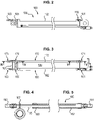
- the element 110 is located on the side of a support frame, for example a vehicle or machine, and the element 120 is capable of displacement relative to this support frame under the actuation of an extension cylinder. 130.
- the cylinder and the piston rod of the extension cylinder 130 are fixed respectively on the elements 110, 120 of the slide arm.
- the extension of the cylinder 130 leads to the extension of the slide arm 100 and respectively the retraction of the cylinder 130 leads to the retraction of the slide arm 100.
- the movable element 120 of the sliding arm 100 carries at its end a piece of equipment 140, for example an articulated bracket as illustrated in the figures 6 to 12 , actuated by at least one on-board hydraulic cylinder 150.
- the tubes 162, 172 are of large diameter while the tubes 165 and 175 are of smaller diameter and are engaged respectively in the tubes 162, 172.
- the sealed connection between the tubes 162, 165 and respectively 172, 175 can be ensured by any appropriate means, preferably by means of O-rings or the like arranged between the outer surface of the small-diameter tubes 165, 175 and the inner surface of the tubes. 162, 172 large diameter.
- Such O-rings are schematized under the reference 180 on the figure 4 .
- seals 180 can be the subject of many variants depending on the fluid pressure involved.
- the two pairs 160, 170 of tubes 162, 165 and 172, 175 are arranged parallel to the longitudinal axis of the extension cylinder 130 and therefore also parallel to the direction of elongation of the elements 110, 120 of the slide arm and are fixed respectively on the cylinder and on the piston rod of the extension cylinder 130.
- the fixing of the tubes 162, 172 on the cylinder of the extension jack 130 and the fixing of the tubes 165, 175 on the piston rod of the extension jack 130, are ensured by any suitable means, for example by means of plates 166, 167 sized to take up the forces.
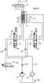
- the upstream ends 161, 171 of the tubes 162, 172 are connected to supply means which will be described below with regard to the figure 8 .
- downstream ends 163, 173 of the downstream tubes 165, 175 are connected to the respective chambers 152, 154 of the on-board cylinder 150.
- the cumulative length of the two tubes 162, 165 and 172, 175 respectively must be at least equal to the maximum extended length of the slide arm 100.
- the overlapping length of the two tubes 162, 165 and 172, 175 respectively must be at least equal to the travel of the slider arm 100 between its retracted and extended positions respectively.
- the tubes 162, 165 and 172, 175 are dimensioned in order to resist the supply pressure and to avoid any risk of buckling.
- a distributor 220 for example four-way, three-position, makes it possible to selectively direct the oil delivered by the pump 210 towards the extension jack 130.
- an inlet 221 of the distributor 220 is connected via a non-return valve 230 to the outlet of the pump 210.
- a second inlet 222 of the distributor 220 is connected to a return conduit 232 which opens into the tank 200 via a filter 234.
- the two outlets 223, 224 of the distributor 220 are respectively connected to the chambers 132, 134 arranged respectively on either side of the piston 131 of the extension jack 130.
- the distributor 220 In the rest position illustrated on the figure 8 , the distributor 220 is in a closed center. The four ports 221, 222, 223 and 224 are isolated. The extension cylinder 130 is stationary.
- the distributor 220 ensures the connection of the inlet 221 to the outlet 223 and the connection of the inlet 222 to the outlet 224 causing the supply of the chamber 132 and consequently the extension of the cylinder 130.
- the distributor 220 ensures the cross supply of the output 224 by the input 221 and of the outlet 223 via the inlet 222 thus ensuring the supply of the opposite chamber 134 of the jack 130 and consequently its retraction.
- Distributor 240 is typically of the four-way, three-position type.
- the distributor 240 In the rest position shown on the figure 8 , the distributor 240 is in open center.
- the two outlets 243, 244 also connected to the upstream ends 161, 171 of the supply tubes 162, 172 are connected to the reservoir 200.
- the distributor 240 ensures the connection of the first inlet 241 with the first outlet 243 and the connection of the second inlet 242 with the second outlet 244 to ensure the supply of the retraction chamber 154 of the cylinder 150 .
- the distributor 240 ensures the cross connection of the inlet 241 with the outlet 244 and of the inlet 242 with the outlet 243.
- the second chamber 152 is supplied with pressurized oil to ensure the extension of the cylinder actuating the equipment 140.
- the first inlet 241 is connected to the outlet of the pump 210 via a non-return valve 236.
- the second inlet 242 of the distributor 240 is connected to the tank 200 via the filter 234.
- the supply circuit also comprises means making it possible to modulate the flow rate supplied by the pump 210 to the jack 150 in order to define two actuation speeds.
- Such means can be formed for example by a restriction 238 placed between the outlet of the pump 210 and the non-return valve 236 to define a low oil flow and consequently a low actuation speed of cylinder 250 and a distributor 239 forming an on/off valve placed in parallel with restriction 238.
- restriction 238 In the open position of valve 239, restriction 238 is short-circuited and a high flow rate can be sent to actuator 250.
- the distributor 240 is placed automatically in the middle position in the open center when the extension cylinder 130 is controlled in extension/retraction.
- the open center position of the distributor 240 makes it possible to avoid any risk of bursting of the tubes 162, 165 and 172, 175.
- the power circuit is controlled such that movement of the powered ram 150 is only permitted when the extension ram 130 is stationary.
- the system according to the invention is compact and can be easily integrated on the slide arm 100.
- FIG. 9 to 12 illustrate the application of the system according to the invention on a lifting arm 100 comprising an articulated jib crane 140.
Landscapes
- Engineering & Computer Science (AREA)
- Mechanical Engineering (AREA)
- Transportation (AREA)
- Physics & Mathematics (AREA)
- Fluid Mechanics (AREA)
- General Engineering & Computer Science (AREA)
- Actuator (AREA)
- Fluid-Pressure Circuits (AREA)
- Vehicle Body Suspensions (AREA)
- Lighting Device Outwards From Vehicle And Optical Signal (AREA)
- Seats For Vehicles (AREA)
Applications Claiming Priority (1)
| Application Number | Priority Date | Filing Date | Title |
|---|---|---|---|
| FR1760582A FR3073584B1 (fr) | 2017-11-10 | 2017-11-10 | Systeme telescopique comprenant en extremite un equipement actionne par un verin |
Publications (2)
| Publication Number | Publication Date |
|---|---|
| EP3483111A1 EP3483111A1 (fr) | 2019-05-15 |
| EP3483111B1 true EP3483111B1 (fr) | 2022-11-30 |
Family
ID=61003181
Family Applications (1)
| Application Number | Title | Priority Date | Filing Date |
|---|---|---|---|
| EP18205077.3A Active EP3483111B1 (fr) | 2017-11-10 | 2018-11-08 | Système télescopique comprenant en extrémité un équipement actionné par un vérin |
Country Status (5)
| Country | Link |
|---|---|
| EP (1) | EP3483111B1 (pl) |
| ES (1) | ES2935485T3 (pl) |
| FI (1) | FI3483111T3 (pl) |
| FR (1) | FR3073584B1 (pl) |
| PL (1) | PL3483111T3 (pl) |
Families Citing this family (2)
| Publication number | Priority date | Publication date | Assignee | Title |
|---|---|---|---|---|
| SE543577C2 (en) * | 2019-08-26 | 2021-04-06 | Epiroc Rock Drills Ab | A mining machine and a method for rock excavations, as well as a method for conveying hydraulic fluid using the mining machine |
| IT202200018219A1 (it) * | 2022-09-07 | 2024-03-07 | Oleodinamica Panni S R L | Dispositivo per alimentare e per spostare uno strumento idraulico, sistema e automezzo |
Family Cites Families (4)
| Publication number | Priority date | Publication date | Assignee | Title |
|---|---|---|---|---|
| NL9301464A (nl) * | 1993-08-24 | 1995-03-16 | Ruiter Verenigde Bedrijven B V | Telescopische arm. |
| JP2841016B2 (ja) * | 1993-11-08 | 1998-12-24 | 小松メック株式会社 | リーチタワークレーンの操作制御方法および装置 |
| ITTO20110403A1 (it) * | 2011-05-06 | 2012-11-07 | B O B Sistemi Idraulici S P A | Braccio telescopico per una gru di movimentazione di un organo accessorio |
| ES2457238T3 (es) * | 2011-09-07 | 2014-04-25 | Epsilon Kran Gmbh. | Brazo de grúa telescópico |
-
2017
- 2017-11-10 FR FR1760582A patent/FR3073584B1/fr not_active Expired - Fee Related
-
2018
- 2018-11-08 EP EP18205077.3A patent/EP3483111B1/fr active Active
- 2018-11-08 FI FIEP18205077.3T patent/FI3483111T3/fi active
- 2018-11-08 PL PL18205077.3T patent/PL3483111T3/pl unknown
- 2018-11-08 ES ES18205077T patent/ES2935485T3/es active Active
Also Published As
| Publication number | Publication date |
|---|---|
| FR3073584B1 (fr) | 2020-07-03 |
| ES2935485T3 (es) | 2023-03-07 |
| EP3483111A1 (fr) | 2019-05-15 |
| PL3483111T3 (pl) | 2023-03-13 |
| FR3073584A1 (fr) | 2019-05-17 |
| FI3483111T3 (fi) | 2023-02-28 |
Similar Documents
| Publication | Publication Date | Title |
|---|---|---|
| FR2501127A1 (fr) | Structure de systeme de roulement pour engin de chantier | |
| WO1994013928A1 (fr) | Stabilisateur a plusieurs bras dans un dispositif de forage ou de carottage | |
| CA2728152A1 (fr) | Actionneur electrohydraulique a pompe integree dans le piston | |
| EP3483111A1 (fr) | Système télescopique comprenant en extrémité un équipement actionné par un vérin | |
| FR2497280A1 (pl) | ||
| FR2735813A1 (fr) | Ensemble destine a un organe telescopique d'avance pour machine de forage de roches | |
| FR2782131A1 (fr) | Dispositif d'actionnement hydraulique, en particulier pour capote de vehicule | |
| FR2616489A1 (fr) | Verin multiple a au moins trois elements coulissants et fleche telescopique en faisant application | |
| FR2824993A1 (fr) | Groupe de relevage hydraulique destine a un systeme d'attelage | |
| FR3096097B1 (fr) | Vérin hydraulique equipé d’un dispositif de ralentissement de fin de course | |
| FR2670716A1 (fr) | Dispositif de securite monte sur un verin hydraulique d'anti-roulis actif. | |
| FR2503641A1 (fr) | Dispositif d'amortissement pour suspension de vehicule | |
| JP4781708B2 (ja) | 作業車輌の油圧システム | |
| EP0952355A2 (fr) | Installation hydraulique avec des vérins synchronisés | |
| FR2634817A1 (fr) | Dispositif pour commander des moyens hydrauliques d'actionnement dans une fleche de forage de roche et une structure de fleche analogue | |
| FR2514338A1 (fr) | Engin elevateur de personnel du type telescopique | |
| FR2734608A1 (fr) | Dispositif hydraulique differentiel pour alimentation et verrouillage de verins de commande a double effet | |
| EP1679282B1 (fr) | Grue à flèche équilibrée dont le bras auxiliaire peut être maintenu vertical | |
| FR2522372A1 (fr) | Verin telescopique hydraulique a plusieurs etages, comprenant une amenee de fluide sous pression situee du cote du piston d'extremite | |
| FR3028589A1 (fr) | Verin hydraulique a transfert de volume interne | |
| FR2938401A1 (fr) | Machine agricole destinee a etre rapportee sur un tracteur et comportant un verin de levage et un verin de delestage d'une unite de travail | |
| FR2731729A1 (fr) | Systeme de commande hydraulique pour chargeur | |
| EP0985830A1 (fr) | Circuit oléodynamique pour l'actionnement de ponts de service pour le levage de véhicules | |
| FR3070003B1 (fr) | Dispositif de regulation hydraulique pour systeme de commande avec amortissement pour rampe de pulverisation, et systeme comprenant ledit dispositif | |
| FR2993325A1 (fr) | Dispositif de commande du deplacement d'un verin hydraulique, notamment pour machines hydrauliques. |
Legal Events
| Date | Code | Title | Description |
|---|---|---|---|
| PUAI | Public reference made under article 153(3) epc to a published international application that has entered the european phase |
Free format text: ORIGINAL CODE: 0009012 |
|
| STAA | Information on the status of an ep patent application or granted ep patent |
Free format text: STATUS: REQUEST FOR EXAMINATION WAS MADE |
|
| 17P | Request for examination filed |
Effective date: 20181108 |
|
| AK | Designated contracting states |
Kind code of ref document: A1 Designated state(s): AL AT BE BG CH CY CZ DE DK EE ES FI FR GB GR HR HU IE IS IT LI LT LU LV MC MK MT NL NO PL PT RO RS SE SI SK SM TR |
|
| AX | Request for extension of the european patent |
Extension state: BA ME |
|
| GRAP | Despatch of communication of intention to grant a patent |
Free format text: ORIGINAL CODE: EPIDOSNIGR1 |
|
| STAA | Information on the status of an ep patent application or granted ep patent |
Free format text: STATUS: GRANT OF PATENT IS INTENDED |
|
| RIC1 | Information provided on ipc code assigned before grant |
Ipc: B60P 1/54 20060101ALI20220601BHEP Ipc: B66C 13/12 20060101ALI20220601BHEP Ipc: F15B 15/14 20060101ALI20220601BHEP Ipc: B66C 23/70 20060101AFI20220601BHEP |
|
| INTG | Intention to grant announced |
Effective date: 20220627 |
|
| GRAS | Grant fee paid |
Free format text: ORIGINAL CODE: EPIDOSNIGR3 |
|
| GRAA | (expected) grant |
Free format text: ORIGINAL CODE: 0009210 |
|
| STAA | Information on the status of an ep patent application or granted ep patent |
Free format text: STATUS: THE PATENT HAS BEEN GRANTED |
|
| AK | Designated contracting states |
Kind code of ref document: B1 Designated state(s): AL AT BE BG CH CY CZ DE DK EE ES FI FR GB GR HR HU IE IS IT LI LT LU LV MC MK MT NL NO PL PT RO RS SE SI SK SM TR |
|
| REG | Reference to a national code |
Ref country code: CH Ref legal event code: EP Ref country code: GB Ref legal event code: FG4D Free format text: NOT ENGLISH |
|
| REG | Reference to a national code |
Ref country code: AT Ref legal event code: REF Ref document number: 1534561 Country of ref document: AT Kind code of ref document: T Effective date: 20221215 |
|
| REG | Reference to a national code |
Ref country code: IE Ref legal event code: FG4D Free format text: LANGUAGE OF EP DOCUMENT: FRENCH |
|
| REG | Reference to a national code |
Ref country code: DE Ref legal event code: R096 Ref document number: 602018043590 Country of ref document: DE |
|
| REG | Reference to a national code |
Ref country code: NL Ref legal event code: FP |
|
| REG | Reference to a national code |
Ref country code: SE Ref legal event code: TRGR |
|
| REG | Reference to a national code |
Ref country code: ES Ref legal event code: FG2A Ref document number: 2935485 Country of ref document: ES Kind code of ref document: T3 Effective date: 20230307 |
|
| REG | Reference to a national code |
Ref country code: LT Ref legal event code: MG9D |
|
| PG25 | Lapsed in a contracting state [announced via postgrant information from national office to epo] |
Ref country code: PT Free format text: LAPSE BECAUSE OF FAILURE TO SUBMIT A TRANSLATION OF THE DESCRIPTION OR TO PAY THE FEE WITHIN THE PRESCRIBED TIME-LIMIT Effective date: 20230331 Ref country code: NO Free format text: LAPSE BECAUSE OF FAILURE TO SUBMIT A TRANSLATION OF THE DESCRIPTION OR TO PAY THE FEE WITHIN THE PRESCRIBED TIME-LIMIT Effective date: 20230228 Ref country code: LT Free format text: LAPSE BECAUSE OF FAILURE TO SUBMIT A TRANSLATION OF THE DESCRIPTION OR TO PAY THE FEE WITHIN THE PRESCRIBED TIME-LIMIT Effective date: 20221130 |
|
| PG25 | Lapsed in a contracting state [announced via postgrant information from national office to epo] |
Ref country code: RS Free format text: LAPSE BECAUSE OF FAILURE TO SUBMIT A TRANSLATION OF THE DESCRIPTION OR TO PAY THE FEE WITHIN THE PRESCRIBED TIME-LIMIT Effective date: 20221130 Ref country code: LV Free format text: LAPSE BECAUSE OF FAILURE TO SUBMIT A TRANSLATION OF THE DESCRIPTION OR TO PAY THE FEE WITHIN THE PRESCRIBED TIME-LIMIT Effective date: 20221130 Ref country code: IS Free format text: LAPSE BECAUSE OF FAILURE TO SUBMIT A TRANSLATION OF THE DESCRIPTION OR TO PAY THE FEE WITHIN THE PRESCRIBED TIME-LIMIT Effective date: 20230330 Ref country code: HR Free format text: LAPSE BECAUSE OF FAILURE TO SUBMIT A TRANSLATION OF THE DESCRIPTION OR TO PAY THE FEE WITHIN THE PRESCRIBED TIME-LIMIT Effective date: 20221130 Ref country code: GR Free format text: LAPSE BECAUSE OF FAILURE TO SUBMIT A TRANSLATION OF THE DESCRIPTION OR TO PAY THE FEE WITHIN THE PRESCRIBED TIME-LIMIT Effective date: 20230301 |
|
| PG25 | Lapsed in a contracting state [announced via postgrant information from national office to epo] |
Ref country code: SM Free format text: LAPSE BECAUSE OF FAILURE TO SUBMIT A TRANSLATION OF THE DESCRIPTION OR TO PAY THE FEE WITHIN THE PRESCRIBED TIME-LIMIT Effective date: 20221130 Ref country code: RO Free format text: LAPSE BECAUSE OF FAILURE TO SUBMIT A TRANSLATION OF THE DESCRIPTION OR TO PAY THE FEE WITHIN THE PRESCRIBED TIME-LIMIT Effective date: 20221130 Ref country code: EE Free format text: LAPSE BECAUSE OF FAILURE TO SUBMIT A TRANSLATION OF THE DESCRIPTION OR TO PAY THE FEE WITHIN THE PRESCRIBED TIME-LIMIT Effective date: 20221130 Ref country code: DK Free format text: LAPSE BECAUSE OF FAILURE TO SUBMIT A TRANSLATION OF THE DESCRIPTION OR TO PAY THE FEE WITHIN THE PRESCRIBED TIME-LIMIT Effective date: 20221130 |
|
| PG25 | Lapsed in a contracting state [announced via postgrant information from national office to epo] |
Ref country code: SK Free format text: LAPSE BECAUSE OF FAILURE TO SUBMIT A TRANSLATION OF THE DESCRIPTION OR TO PAY THE FEE WITHIN THE PRESCRIBED TIME-LIMIT Effective date: 20221130 Ref country code: AL Free format text: LAPSE BECAUSE OF FAILURE TO SUBMIT A TRANSLATION OF THE DESCRIPTION OR TO PAY THE FEE WITHIN THE PRESCRIBED TIME-LIMIT Effective date: 20221130 |
|
| REG | Reference to a national code |
Ref country code: DE Ref legal event code: R097 Ref document number: 602018043590 Country of ref document: DE |
|
| PLBE | No opposition filed within time limit |
Free format text: ORIGINAL CODE: 0009261 |
|
| STAA | Information on the status of an ep patent application or granted ep patent |
Free format text: STATUS: NO OPPOSITION FILED WITHIN TIME LIMIT |
|
| 26N | No opposition filed |
Effective date: 20230831 |
|
| PG25 | Lapsed in a contracting state [announced via postgrant information from national office to epo] |
Ref country code: SI Free format text: LAPSE BECAUSE OF FAILURE TO SUBMIT A TRANSLATION OF THE DESCRIPTION OR TO PAY THE FEE WITHIN THE PRESCRIBED TIME-LIMIT Effective date: 20221130 |
|
| REG | Reference to a national code |
Ref country code: AT Ref legal event code: UEP Ref document number: 1534561 Country of ref document: AT Kind code of ref document: T Effective date: 20221130 |
|
| PG25 | Lapsed in a contracting state [announced via postgrant information from national office to epo] |
Ref country code: MC Free format text: LAPSE BECAUSE OF FAILURE TO SUBMIT A TRANSLATION OF THE DESCRIPTION OR TO PAY THE FEE WITHIN THE PRESCRIBED TIME-LIMIT Effective date: 20221130 |
|
| PG25 | Lapsed in a contracting state [announced via postgrant information from national office to epo] |
Ref country code: LU Free format text: LAPSE BECAUSE OF NON-PAYMENT OF DUE FEES Effective date: 20231108 |
|
| GBPC | Gb: european patent ceased through non-payment of renewal fee |
Effective date: 20231108 |
|
| PG25 | Lapsed in a contracting state [announced via postgrant information from national office to epo] |
Ref country code: MC Free format text: LAPSE BECAUSE OF FAILURE TO SUBMIT A TRANSLATION OF THE DESCRIPTION OR TO PAY THE FEE WITHIN THE PRESCRIBED TIME-LIMIT Effective date: 20221130 Ref country code: LU Free format text: LAPSE BECAUSE OF NON-PAYMENT OF DUE FEES Effective date: 20231108 |
|
| REG | Reference to a national code |
Ref country code: IE Ref legal event code: MM4A |
|
| PG25 | Lapsed in a contracting state [announced via postgrant information from national office to epo] |
Ref country code: IE Free format text: LAPSE BECAUSE OF NON-PAYMENT OF DUE FEES Effective date: 20231108 |
|
| PG25 | Lapsed in a contracting state [announced via postgrant information from national office to epo] |
Ref country code: GB Free format text: LAPSE BECAUSE OF NON-PAYMENT OF DUE FEES Effective date: 20231108 |
|
| PG25 | Lapsed in a contracting state [announced via postgrant information from national office to epo] |
Ref country code: IE Free format text: LAPSE BECAUSE OF NON-PAYMENT OF DUE FEES Effective date: 20231108 Ref country code: GB Free format text: LAPSE BECAUSE OF NON-PAYMENT OF DUE FEES Effective date: 20231108 |
|
| PG25 | Lapsed in a contracting state [announced via postgrant information from national office to epo] |
Ref country code: BG Free format text: LAPSE BECAUSE OF FAILURE TO SUBMIT A TRANSLATION OF THE DESCRIPTION OR TO PAY THE FEE WITHIN THE PRESCRIBED TIME-LIMIT Effective date: 20221130 |
|
| PG25 | Lapsed in a contracting state [announced via postgrant information from national office to epo] |
Ref country code: BG Free format text: LAPSE BECAUSE OF FAILURE TO SUBMIT A TRANSLATION OF THE DESCRIPTION OR TO PAY THE FEE WITHIN THE PRESCRIBED TIME-LIMIT Effective date: 20221130 |
|
| PG25 | Lapsed in a contracting state [announced via postgrant information from national office to epo] |
Ref country code: CY Free format text: LAPSE BECAUSE OF FAILURE TO SUBMIT A TRANSLATION OF THE DESCRIPTION OR TO PAY THE FEE WITHIN THE PRESCRIBED TIME-LIMIT; INVALID AB INITIO Effective date: 20181108 |
|
| PG25 | Lapsed in a contracting state [announced via postgrant information from national office to epo] |
Ref country code: HU Free format text: LAPSE BECAUSE OF FAILURE TO SUBMIT A TRANSLATION OF THE DESCRIPTION OR TO PAY THE FEE WITHIN THE PRESCRIBED TIME-LIMIT; INVALID AB INITIO Effective date: 20181108 |
|
| PGFP | Annual fee paid to national office [announced via postgrant information from national office to epo] |
Ref country code: NL Payment date: 20251028 Year of fee payment: 8 |
|
| REG | Reference to a national code |
Ref country code: CH Ref legal event code: U11 Free format text: ST27 STATUS EVENT CODE: U-0-0-U10-U11 (AS PROVIDED BY THE NATIONAL OFFICE) Effective date: 20251201 |
|
| PG25 | Lapsed in a contracting state [announced via postgrant information from national office to epo] |
Ref country code: TR Free format text: LAPSE BECAUSE OF FAILURE TO SUBMIT A TRANSLATION OF THE DESCRIPTION OR TO PAY THE FEE WITHIN THE PRESCRIBED TIME-LIMIT Effective date: 20221130 |
|
| PGFP | Annual fee paid to national office [announced via postgrant information from national office to epo] |
Ref country code: DE Payment date: 20251117 Year of fee payment: 8 |
|
| PGFP | Annual fee paid to national office [announced via postgrant information from national office to epo] |
Ref country code: AT Payment date: 20251024 Year of fee payment: 8 |
|
| PGFP | Annual fee paid to national office [announced via postgrant information from national office to epo] |
Ref country code: FI Payment date: 20251024 Year of fee payment: 8 Ref country code: IT Payment date: 20251107 Year of fee payment: 8 |
|
| PGFP | Annual fee paid to national office [announced via postgrant information from national office to epo] |
Ref country code: FR Payment date: 20251014 Year of fee payment: 8 |
|
| PGFP | Annual fee paid to national office [announced via postgrant information from national office to epo] |
Ref country code: BE Payment date: 20251120 Year of fee payment: 8 |
|
| PGFP | Annual fee paid to national office [announced via postgrant information from national office to epo] |
Ref country code: CH Payment date: 20251201 Year of fee payment: 8 Ref country code: SE Payment date: 20251121 Year of fee payment: 8 |
|
| PGFP | Annual fee paid to national office [announced via postgrant information from national office to epo] |
Ref country code: CZ Payment date: 20251107 Year of fee payment: 8 |
|
| PGFP | Annual fee paid to national office [announced via postgrant information from national office to epo] |
Ref country code: PL Payment date: 20251020 Year of fee payment: 8 |
|
| PGFP | Annual fee paid to national office [announced via postgrant information from national office to epo] |
Ref country code: ES Payment date: 20251210 Year of fee payment: 8 |