EP3483094A1 - Sensoranordnung zur bestimmung einer veränderlichen spannung eines umlaufenden ketten- oder riementriebes - Google Patents
Sensoranordnung zur bestimmung einer veränderlichen spannung eines umlaufenden ketten- oder riementriebes Download PDFInfo
- Publication number
- EP3483094A1 EP3483094A1 EP18201682.4A EP18201682A EP3483094A1 EP 3483094 A1 EP3483094 A1 EP 3483094A1 EP 18201682 A EP18201682 A EP 18201682A EP 3483094 A1 EP3483094 A1 EP 3483094A1
- Authority
- EP
- European Patent Office
- Prior art keywords
- sensor
- sensor arrangement
- chain
- inductive sensor
- compression spring
- Prior art date
- Legal status (The legal status is an assumption and is not a legal conclusion. Google has not performed a legal analysis and makes no representation as to the accuracy of the status listed.)
- Granted
Links
Images



Classifications
-
- F—MECHANICAL ENGINEERING; LIGHTING; HEATING; WEAPONS; BLASTING
- F16—ENGINEERING ELEMENTS AND UNITS; GENERAL MEASURES FOR PRODUCING AND MAINTAINING EFFECTIVE FUNCTIONING OF MACHINES OR INSTALLATIONS; THERMAL INSULATION IN GENERAL
- F16H—GEARING
- F16H7/00—Gearings for conveying rotary motion by endless flexible members
- F16H7/08—Means for varying tension of belts, ropes or chains
-
- B—PERFORMING OPERATIONS; TRANSPORTING
- B65—CONVEYING; PACKING; STORING; HANDLING THIN OR FILAMENTARY MATERIAL
- B65G—TRANSPORT OR STORAGE DEVICES, e.g. CONVEYORS FOR LOADING OR TIPPING, SHOP CONVEYOR SYSTEMS OR PNEUMATIC TUBE CONVEYORS
- B65G23/00—Driving gear for endless conveyors; Belt- or chain-tensioning arrangements
- B65G23/44—Belt or chain tensioning arrangements
-
- F—MECHANICAL ENGINEERING; LIGHTING; HEATING; WEAPONS; BLASTING
- F16—ENGINEERING ELEMENTS AND UNITS; GENERAL MEASURES FOR PRODUCING AND MAINTAINING EFFECTIVE FUNCTIONING OF MACHINES OR INSTALLATIONS; THERMAL INSULATION IN GENERAL
- F16H—GEARING
- F16H7/00—Gearings for conveying rotary motion by endless flexible members
- F16H7/08—Means for varying tension of belts, ropes or chains
- F16H2007/0802—Actuators for final output members
- F16H2007/0806—Compression coil springs
-
- F—MECHANICAL ENGINEERING; LIGHTING; HEATING; WEAPONS; BLASTING
- F16—ENGINEERING ELEMENTS AND UNITS; GENERAL MEASURES FOR PRODUCING AND MAINTAINING EFFECTIVE FUNCTIONING OF MACHINES OR INSTALLATIONS; THERMAL INSULATION IN GENERAL
- F16H—GEARING
- F16H7/00—Gearings for conveying rotary motion by endless flexible members
- F16H7/08—Means for varying tension of belts, ropes or chains
- F16H2007/0861—Means for varying tension of belts, ropes or chains comprising means for sensing tensioner position
-
- F—MECHANICAL ENGINEERING; LIGHTING; HEATING; WEAPONS; BLASTING
- F16—ENGINEERING ELEMENTS AND UNITS; GENERAL MEASURES FOR PRODUCING AND MAINTAINING EFFECTIVE FUNCTIONING OF MACHINES OR INSTALLATIONS; THERMAL INSULATION IN GENERAL
- F16H—GEARING
- F16H7/00—Gearings for conveying rotary motion by endless flexible members
- F16H7/08—Means for varying tension of belts, ropes or chains
- F16H2007/0863—Finally actuated members, e.g. constructional details thereof
- F16H2007/0872—Sliding members
-
- F—MECHANICAL ENGINEERING; LIGHTING; HEATING; WEAPONS; BLASTING
- F16—ENGINEERING ELEMENTS AND UNITS; GENERAL MEASURES FOR PRODUCING AND MAINTAINING EFFECTIVE FUNCTIONING OF MACHINES OR INSTALLATIONS; THERMAL INSULATION IN GENERAL
- F16H—GEARING
- F16H7/00—Gearings for conveying rotary motion by endless flexible members
- F16H7/08—Means for varying tension of belts, ropes or chains
- F16H2007/0889—Path of movement of the finally actuated member
- F16H2007/0891—Linear path
Definitions
- the invention relates to a sensor arrangement for determining a variable voltage of a circulating chain or belt drive, comprising a fixed to a body spring element, which is in operative connection with the chain or belt drive and an inductive sensor which monitors voltage-dependent changes of the spring element, and a Clamping system for using the sensor arrangement.
- Clamping systems are used particularly in conveyor systems to absorb vibrations, wear or temperature fluctuations that express themselves in longitudinal dimensions.
- a chain or belt tensioning device for a chain or belt on a conveyor which includes a base member, a chain guide profile with a chain or belt guide member slidably mounted in or on the base member and one between the base member and the chain guide profile shows acting spring element.
- An inductive sensor is attached to the base element, wherein a metallic initiator element is arranged on the chain guide profile of the side facing the sensor.
- the DE 42 39 635 A1 shows a method and a device for position detection of valve rod movements of electropneumatic voltage regulators, in which an RF oscillation within an LC resonant circuit for generating a high-frequency electromagnetic alternating field is excited in an inductively operating sensor, wherein an electrically conductive body moved by the valve rod radiates the HF Oscillation attenuated path-dependent.
- the invention has for its object to provide a sensor arrangement for determining a variable voltage of a revolving chain or belt drive, wherein the detection range of the sensor is smaller than the travel and still the variable voltage can be reliably determined.
- the object is achieved in that the inductive sensor for detecting a variable distance of a plurality of spring coils of the spring element formed as a metallic compression spring is arranged directly opposite one another these spring coils.
- the inductive sensor extends axially to the compression spring.
- This axial arrangement reduces the stressed space for the sensor assembly and thus increases the possible applications of the sensor arrangement.
- the compression spring may also be formed as a spiral spring.
- the inductive sensor is disposed within the compression spring, wherein an inner diameter of the compression spring is greater than an outer diameter of the inductive sensor. This ensures that no mechanical contact between pressure spring and sensor occurs and can be reliably determined by the contactless detection of the distance of the spring coils of the state of tension of the chain or belt drive.
- the inductive sensor extends radially to the compression spring. This arrangement allows a particularly accurate detection of the changing distance, since the detection range of the sensor can be brought close to the spring coils.
- the compression spring consists of a steel.
- the inductive sensor comprises a resonant circuit whose damping is proportional to the variable voltage. Since in the compression of the compression spring by the compression of the spring coils by the inductive sensor more metal is detected, the damping of the resonant circuit, which is utilized as a signal for the changed voltage increases.
- the inductive sensor has an analogue and / or digital output and / or an I / O link interface, wherein programmable status information can be output.
- an acceleration sensor is integrated in the inductive sensor.
- a development of the invention comprises a tensioning system for a chain or belt drive, in particular for a conveyor system, with a sensor arrangement for determining a variable tension of the chain or belt drive.
- the sensor arrangement is designed according to at least one feature described in this patent application.
- the sensor arrangement comprises a chain or belt drive bearing chuck, which is mounted on the compression spring, which is arranged in a clamping box, in which the chuck dives in dependence on the voltage.
- the sensor assembly is attached to a lever arm which is fixedly connected to a flange of the clamping box.
- the monitoring of the changing voltage by changing the damping due to overlaps of the detection surface of the inductive sensor and the lever arm.
- the inductive sensor is firmly connected to the flange of the clamping box and thus experiences no rotational movement, whereby a falsification of the measurement result is prevented.
- the sensor arrangement is arranged in the clamping box, which has a smooth surface. This prevents that during the movement of the compression spring relative to the arranged inside the compression spring inductive Sensor a faulty sensor signal is issued as a result of touching both.
- Fig. 1 is a principle of a conveyor system shown.
- driven belts or chains 2 are used, which are endless and are driven by a wheel 3 circumferentially and have at least one further deflection point 4.
- a clamping system 5 by means of a clamping system 5, a permanent, uniform bias on the chain 2 or the belt is maintained.
- a clamping system 5 is to be considered, in which the bias of a chain 2 is to be maintained.
- a clamping system 5 is used, which according to the FIGS. 2 to 4 from a clamping box 6 and a clamping head. 7 is formed.
- a metallic compression spring 8 is arranged, which carries the chuck 7. The compression spring 8 is fixed to a base body 9 of the clamping box 6 and expands within the clamping box 6 in a linear direction between the base body 9 and the clamping head 7. According to Fig.
- an inductive sensor 10 the detection area comprises a plurality of spring coils 11 of the compression spring 8.
- a non-illustrated LC resonant circuit is arranged, which is connected to a signal evaluation, also not shown.
- the unloaded state of the compression spring 8 is in Fig. 2b shown. If the distance between the main body 9 and the chain 2 changes, the compression spring 8 is compressed, as shown in FIG Fig. 2c is shown.
- the inductive sensor 10 arranged inside the compression spring 8 detects more metal, which leads to a higher damping of the resonant circuit installed in the inductive sensor 10.
- the output signal of the inductive sensor 10 thus provides information about the clamping state, ie the distance between the base body 9 and chain 2.
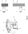
- FIG. 3 shows a further embodiment of the clamping system according to the invention, in which the inductive sensor 10 is arranged radially to the compression spring 8 ( Fig. 3a ).
- the inductive sensor 10 is mounted within a wall of the clamping box 6.
- the compression spring 8 By means of the compression spring 8, the entire travel of the clamping head 7 is monitored. Since the detection range of the inductive sensor 10 is very small in order to map the complete stroke of the clamping head 7, the monitoring takes place by considering the change in the distance of the spring coils 11 of the compression spring 8 (FIG. Fig. 3b, 3c ).
- a lever arm 12 which is fixedly secured to the base body 9, for example a flange of the clamping box 6, carries the inductive sensor 10, which extends parallel to the clamping box 6.
- the monitoring of the movement of the clamping head 7 by the change in the damping of the resonant circuit, which is included in the inductive sensor 10, due to a change takes place the distance between the detection surface of the sensor 10 and the clamping head 7 .. Since the inductive sensor 10 is fixedly arranged on the base body 9, this thus experiences no movement.
- the conveyor belt 2 is, for example, a roller conveyor belt which conveys the objects 14.
- the conveyor belt is fixed and can not yield. If there is a change in the thickness of the objects 14, the angle of the clamping system 5 will change.
- the tensioning system has a lever arm and a pressure roller 13. The fact that the sensor detects the clamping system 5, the sensor will detect the change in angle, whereby the contact pressure or the thickness of the objects can be detected.
- the proposed solution By the proposed solution, the current state of tension of the chain or belt drive can be better monitored. At the same time a long-term measurement is possible. Thus, there is the possibility to schedule maintenance in good time and avoid disruptions. Furthermore, vibrations in the drive can be measured in order to draw conclusions about the operational capability of the conveyor system. Additionally, the vibrations may provide information about the use of the conveyor, e.g. about torque fluctuations or whether a constant torque is set.
- the proposed system can also be applied in other areas, e.g. in vibration dampers, where by the spring monitoring a vibration amplitude can be recorded. In processes can be monitored with the proposed solution, whether a spring is overloaded by this is compressed to block length or whether a tension spring is deflected too much.
- clamping levers instead of the clamping box the way for the detection of the entire clamping range with an inductive sensor is usually not suitable.
- the detection of the clamping path or an angular change is not directly on the chain or tensioning wheel, but on the body.
- the use of clamping levers is due to relatively simple design for optimal retrofitting, as well as for the standard equipment, since no reworking is necessary.
- the attachment is made by an adapter.
- different clamping lever sizes can be used.
- the output signal has a high signal amplitude.
Landscapes
- Engineering & Computer Science (AREA)
- Mechanical Engineering (AREA)
- General Engineering & Computer Science (AREA)
- Control Of Conveyors (AREA)
- Devices For Conveying Motion By Means Of Endless Flexible Members (AREA)
Abstract
Description
- Die Erfindung betrifft eine Sensoranordnung zur Bestimmung einer veränderlichen Spannung eines umlaufenden Ketten- oder Riementriebes, umfassend ein an einem Grundkörper befestigtes Federelement, das mit dem Ketten-oder Riementrieb in einer Wirkverbindung steht und einen induktiven Sensor, welcher spannungsabhängige Änderungen des Federelementes überwacht, sowie ein Spannsystem zur Verwendung der Sensoranordnung.
- Spannsysteme werden insbesondere bei Förderanlagen genutzt, um Schwingungen, Verschleiß oder Temperaturschwankungen, die sich in Längsausdehnungen ausdrücken, abzufangen.
- Aus der
DE 20 2015 104 860 U1 ist eine Ketten- oder Riemenspannvorrichtung für eine Kette oder einen Riemen an einer Förderanlage bekannt, welche ein Basiselement, ein Kettenführungsprofil mit einem Führungselement für die Kette oder den Riemen, der verschiebbar in oder an dem Basiselement gelagert ist und eine zwischen dem Basiselement und dem Kettenführungsprofil wirkendes Federelement aufzeigt. Am Basiselement ist ein induktiver Sensor angebracht, wobei am Kettenführungsprofil der zum Sensor weisenden Seite ein metallisches Initiatorelement angeordnet ist. Mittels dieser Anordnung wird eine bestimmte Position des Kettenführungsprofils gegenüber dem Basiselement erfasst, wodurch ein Nachlassen einer Kettenspannung erfasst wird. - Bei solchen Spannsystemen für Fördersysteme ist es sehr aufwändig, den kompletten Verfahrweg zu überwachen, da der Verfahrweg deutlich größer ist als ein Detektionsbereich des induktiven Sensors.
- Die
DE 42 39 635 A1 zeigt ein Verfahren und eine Einrichtung zur Wegerfassung von Ventilstangenbewegungen elektropneumatischer Spannungsregler, bei welchem in einem induktiv arbeitenden Sensor eine HF-Oszillation innerhalb eines LC-Resonanzkreises zur Erzeugung eines hochfrequenten elektromagnetischen Wechselfeldes angeregt wird, wobei ein von der Ventilstange mitbewegter elektrisch leitfähiger Körper die HF-Oszillation wegabhängig bedämpft. - Der Erfindung liegt die Aufgabe zugrunde, eine Sensoranordnung zur Bestimmung einer veränderlichen Spannung eines umlaufenden Ketten- oder Riementriebes anzugeben, bei welcher der Detektionsbereich des Sensors kleiner ist als der Verfahrweg und trotzdem die veränderliche Spannung zuverlässig bestimmt werden kann.
- Erfindungsgemäß ist die Aufgabe dadurch gelöst, dass der induktive Sensor zur Detektion eines veränderlichen Abstandes von mehreren Federwindungen des als metallische Druckfeder ausgebildeten Federelementes zueinander direkt gegenüberliegend diesen Federwindungen angeordnet ist. Dies hat den Vorteil, dass durch die Betrachtung der Stauchung der Druckfeder, bei welcher sich die Abstände zwischen den Federwindungen der Druckfeder verringern, auch längere Verfahrwege ausgewertet werden können, die außerhalb des Detektionsbereiches des Sensors liegen. Damit ist eine einfache Erfassung der Abstandsänderung der Federwindungen infolge von Schwingungen, Verschleiß oder Temperaturschwankungen möglich.
- Vorteilhafterweise erstreckt sich der induktive Sensor axial zu der Druckfeder. Diese axiale Anordnung verringert den beanspruchten Bauraum für die Sensoranordnung und erhöht somit die Einsatzmöglichkeiten der Sensoranordnung. Die Druckfeder kann auch als Spiralfeder ausgebildet sein.
- In einer Ausführungsform ist der induktive Sensor innerhalb der Druckfeder angeordnet, wobei ein Innendurchmesser der Druckfeder größer als ein Außendurchmesser des induktiven Sensors ist. Dadurch wird sichergestellt, dass kein mechanischer Kontakt zwischen Druckfeder und Sensor auftritt und durch die berührungslose Detektion des Abstandes der Federwindungen der Spannungszustand des Ketten- oder Riementriebes zuverlässig ermittelt werden kann.
- In einer Ausgestaltung erstreckt sich der induktive Sensor radial zu der Druckfeder. Diese Anordnung lässt eine besonders genaue Erfassung des sich ändernden Abstandes zu, da der Detektionsbereich des Sensors nahe an die Federwindungen herangebracht werden kann.
- In einer Variante besteht die Druckfeder aus einem Stahl. Durch die Ausbildung der gesamten Druckfeder aus Stahl wird eine besonders bauraumfreundliche und kostenreduzierende Sensoranordnung geschaffen.
- Vorteilhafterweise umfasst der induktive Sensor einen Schwingkreis, dessen Bedämpfung proportional zur veränderlichen Spannung ist. Da bei der Stauchung der Druckfeder durch das Zusammendrücken der Federwindungen durch den induktiven Sensor mehr Metall detektiert wird, erhöht sich die Bedämpfung des Schwingkreises, welches als Signal für die geänderte Spannung verwertet wird.
- In Weiterbildung der Erfindung weist der induktive Sensor einen analogen und/oder digitalen Ausgang und/oder eine I/O-Link Schnittstelle auf, wobei programmierbare Statusinformationen ausgebbar sind.
- Durch eine im induktiven Sensor verbaute Signalauswertung bzw. Steuer- und Auswerteeinheit kann eine Information über die vorhandene Spannung deutlich sichtbar gemacht werden, beispielsweise über eine Änderung der Ausgangsspannung oder über einen IO-Link, über den eine entsprechende Information ausgegeben wird. Dabei können beispielsweise die Werte ,volle Druckspannung', ,halbe Druckspannung' oder ,keine Druckspannung' über den Ausgang ausgegeben werden.
- Um Schwingungen zu überwachen, ist ein Beschleunigungssensor in dem induktiven Sensor integriert. Mittels dieser Schwingungsüberwachung können Rückschlüsse auf die Lebensdauer der Sensoranordnung, insbesondere des Federlagers, gezogen werden.
- Eine Weiterbildung der Erfindung umfasst ein Spannsystem für einen Ketten- oder Riementrieb, insbesondere für eine Förderanlage, mit einer Sensoranordnung zur Bestimmung einer veränderlichen Spannung des Ketten- oder Riementriebes. Um ein Spannsystem anzugeben, bei welchem der Detektionsbereich des Sensors kleiner ist als der Verfahrweg und trotzdem die veränderliche Spannung zuverlässig bestimmt werden kann, ist die Sensoranordnung nach mindestens einem in dieser Schutzrechtsanmeldung beschriebenen Merkmal ausgebildet.
- Vorteilhafterweise weist die Sensoranordnung einen den Ketten- oder Riementrieb tragenden Spannkopf auf, der auf die Druckfeder aufgesetzt ist, die in einer Spannbox angeordnet ist, in welche der Spannkopf in Abhängigkeit von der Spannung eintaucht.
- In einer Ausgestaltung ist die Sensoranordnung an einem Hebelarm befestigt, welcher fest mit einem Flansch der Spannbox verbunden ist. Dabei erfolgt die Überwachung der sich ändernden Spannung durch die Änderung der Bedämpfung aufgrund von Überschneidungen der Detektionsfläche des induktiven Sensors und dem Hebelarm. Der induktive Sensor ist dabei fest mit dem Flansch der Spannbox verbunden und erfährt somit keine Drehbewegung, wodurch eine Verfälschung des Messergebnisses unterbunden wird.
- In einer Alternative ist die Sensoranordnung in der Spannbox angeordnet, welche eine glatte Oberfläche aufweist. Dadurch wird verhindert, dass bei der Bewegung der Druckfeder relativ zu dem innerhalb der Druckfeder angeordneten induktiven Sensor ein fehlerhaftes Sensorsignal infolge einer Berührung beider ausgegeben wird.
- Die Erfindung lässt zahlreiche Ausführungsformen zu. Zwei davon sollen anhand der in der Zeichnung dargestellten Figuren näher erläutert werden.
- Es zeigen:
-
Fig. 1 eine Prinzipdarstellung einer Förderanlage mit einer Kettenspannvorrichtung, -
Fig. 2 ein erstes Ausführungsbeispiel eines erfindungsgemäßen Spannsystems mit erfindungsgemäßer Sensoranordnung, -
Fig. 3 ein weiteres Ausführungsbeispiel des erfindungsgemäßen Spannsystems mit erfindungsgemäßer Sensoranordnung, -
Fig. 4 ein weiteres Ausführungsbeispiel des erfindungsgemäßen Spannsystems, -
Fig. 5 ein Ausführungsbeispiel für die Anwendung eines erfindungsgemäßen Spannsystems. - In
Fig. 1 ist ein Prinzip einer Förderanlage dargestellt. In dieser Förderanlage 1 kommen angetriebene Riemen oder Ketten 2 zum Einsatz, die endlos ausgebildet sind und von einem Rad 3 umlaufend angetrieben werden und wenigstens eine weitere Umlenkstelle 4 besitzen. Dabei wird mittels eines Spannsystems 5 eine dauerhafte, gleichmäßige Vorspannung an der Kette 2 oder dem Riemen aufrechterhalten. - Im Weiteren soll ein Spannsystem 5 betrachtet werden, bei welcher die Vorspannung einer Kette 2 aufrechterhalten werden soll. Um Schwingungen, Verschleiß (Längsausdehnung der Kette 2) oder Temperaturschwankungen (Längsausdehnung der Kette 2) abzufangen, wird ein Spannsystem 5 verwendet, welches gemäß den
Figuren 2 bis 4 aus einer Spannbox 6 und einem Spannkopf 7 gebildet ist. In der Spannbox 6 ist eine metallische Druckfeder 8 angeordnet, welche den Spannkopf 7 trägt. Die Druckfeder 8 ist an einem Grundkörper 9 der Spannbox 6 befestigt und dehnt sich innerhalb der Spannbox 6 in linearer Richtung zwischen dem Grundkörper 9 und dem Spannkopf 7 aus. GemäßFig. 2a ist innerhalb der Druckfeder 8 ein induktiver Sensor 10 angeordnet, dessen Detektionsbereich mehrere Federwindungen 11 der Druckfeder 8 umfasst. Innerhalb des induktiven Sensors 10 ist ein nicht weiter dargestellter LC-Schwingkreis angeordnet, der mit einer ebenfalls nicht dargestellten Signalauswertung verbunden ist. Der unbelastete Zustand der Druckfeder 8 ist inFig. 2b gezeigt. Ändert sich der Abstand zwischen dem Grundkörper 9 und der Kette 2, so wird die Druckfeder 8 gestaucht, wie es inFig. 2c dargestellt ist. Durch diese Stauchung detektiert der innerhalb der Druckfeder 8 angeordnete induktive Sensor 10 mehr Metall, was zu einer höheren Bedämpfung des in dem induktiven Sensor 10 verbauten Schwingkreises führt. Das Ausgangssignal des induktiven Sensors 10 liefert somit eine Information über den Spannzustand, d.h. den aufgebrachten Abstand zwischen Grundkörper 9 und Kette 2. - In
Fig. 3 ist ein weiteres Ausführungsbeispiel des erfindungsgemäßen Spannsystems gezeigt, bei welchem der induktive Sensor 10 radial zur Druckfeder 8 angeordnet ist (Fig. 3a ). Dabei ist der induktive Sensor 10 innerhalb einer Wandung der Spannbox 6 befestigt. Mittels der Druckfeder 8 wird der gesamte Verfahrweg des Spannkopfes 7 überwacht. Da der Detektionsbereich des induktiven Sensors 10 sehr klein ist, um den vollständigen Hub des Spannkopfes 7 abzubilden, erfolgt die Überwachung durch die Betrachtung der Änderung des Abstandes der Federwindungen 11 der Druckfeder 8 (Fig. 3b, 3c ). - In
Fig. 4 ist ein weiteres Ausführungsbeispiel des erfindungsgemäßen Spannsystems 5 und der erfindungsgemäßen Sensoranordnung dargestellt, bei welchem ein Hebelarm 12, der fest am Grundkörper 9, beispielsweise einem Flansch der Spannbox 6 befestigt ist, den induktiven Sensor 10 trägt, welcher sich parallel zur Spannbox 6 ausdehnt. Dabei erfolgt die Überwachung der Bewegung des Spannkopfes 7 durch die Änderung der Bedämpfung des Schwingkreises, welcher in dem induktiven Sensor 10 enthalten ist, aufgrund von einer Änderung des Abstands zwischen Detektionsfläche vom Sensor 10 und des Spannkopfes 7.. Da der induktive Sensor 10 fest an dem Grundkörper 9 angeordnet ist, erfährt dieser somit keinerlei Bewegung. - Gemäß
Figur 5 erfolgt die Überwachung der Anpresskraft bzw. Dicke von Werkstücken bzw. Objekten. Das Förderband 2 ist beispielsweise ein Rollenförderband, welches die Objekte 14 fördert. Das Förderband ist fixiert und kann nicht nachgeben. Erfolgt eine Änderung der Dicke der Objekte 14 wird sich der Winkel des Spannsystems 5 ändern. Das Spannsystem weist einen Hebelarm und eine Anpressrolle 13 auf. Dadurch, dass der Sensor das Spannsystem 5 erfasst, wird der Sensor die Winkeländerung erfassen, wodurch die Anpresskraft bzw. die Dicke der Objekte erfassbar ist. - Durch die vorgeschlagene Lösung kann der aktuelle Spannzustand des Ketten-oder Riementriebes besser überwacht werden. Gleichzeitig ist auch eine Langzeitmessung möglich. Somit besteht die Möglichkeit, rechtzeitig eine Wartung einzuplanen und Störungen zu vermeiden. Des Weiteren können Schwingungen im Antrieb vermessen werden, um Rückschlüsse auf die Einsatzfähigkeit der Förderanlage zu treffen. Zusätzlich können die Schwingungen Informationen über den Einsatz der Förderanlage geben, z.B. über Drehmomentschwankungen oder ob ein konstantes Drehmoment eingestellt ist. Das vorgeschlagene System kann auch in anderen Bereichen angewandt werden, z.B. bei Schwingungsdämpfern, wo durch die Federüberwachung eine Schwingungsamplitude aufgenommen werden kann. In Prozessen kann mit der vorgeschlagenen Lösung überwacht werden, ob eine Feder überlastet wird, indem diese bis auf Blocklänge gestaucht wird oder ob eine Zugfeder zu stark ausgelenkt wird.
- Bei der alternativen Verwendung von Spannhebeln anstelle der Spannbox ist der Weg für die Detektion des kompletten Spannbereiches mit einem induktiven Sensor normalerweise nicht geeignet. Somit erfolgt die Detektion des Spannweges bzw. eine Winkelveränderung nicht direkt am Ketten- bzw. Spannrad, sondern am Grundkörper. Die Verwendung von Spannhebeln eignet sich aufgrund von relativ einfachem Aufbau für eine optimale Nachrüstung, sowie für die Serienausrüstung, da keine Nacharbeiten notwendig sind. Die Befestigung erfolgt durch einen Adapter. Darüber hinaus können unterschiedliche Spannhebelgrößen verwendet werden. Das ausgegebene Signal hat dabei eine hohe Signalamplitude.
Claims (12)
- Sensoranordnung zur Bestimmung einer veränderlichen Spannung eines umlaufenden Ketten- oder Riementriebes, umfassend ein an einem Grundkörper (9) befestigtes Federelement (8), das mit dem Ketten- oder Riementrieb in einer Wirkverbindung steht und einen induktiven Sensor (10), welcher spannungsabhängige Änderungen des Federelementes (8) überwacht, dadurch gekennzeichnet, dass der induktive Sensor (10) zur Detektion eines veränderlichen Abstandes von mehreren Federwindungen (11) des als metallische Druckfeder ausgebildeten Federelementes (8) zueinander direkt gegenüberliegend diesen Federwindungen (11) angeordnet ist.
- Sensoranordnung nach Anspruch 1, dadurch gekennzeichnet, dass der induktive Sensor (10) sich axial zu der Druckfeder (8) erstreckt.
- Sensoranordnung nach Anspruch 2, dadurch gekennzeichnet, dass der induktive Sensor (10) axial innerhalb der Druckfeder (8) angeordnet ist, wobei ein Innendurchmesser der Druckfeder (8) größer als ein Außendurchmesser des induktiven Sensors (10) ist.
- Sensoranordnung nach Anspruch 1, dadurch gekennzeichnet, dass der induktive Sensor (10) sich radial zu der Druckfeder (8) erstreckt.
- Sensoranordnung nach mindestens einem der vorhergehenden Ansprüche, dadurch gekennzeichnet, dass der induktive Sensor (10) einen Schwingkreis umfasst, dessen Bedämpfung proportional zur veränderlichen Spannung ist.
- Sensoranordnung nach mindestens einem der vorhergehenden Ansprüche, dadurch gekennzeichnet, dass der induktive Sensor einen analogen und/oder digitalen Ausgang und/oder eine I/O-Link Schnittstelle aufweist, wobei programmierbare Statusinformationen ausgebbar sind.
- Sensoranordnung nach mindestens einem der vorhergehenden Ansprüche, dadurch gekennzeichnet, dass ein Beschleunigungssensor zur Überwachung von Schwingungen in dem induktiven Sensor (10) integriert ist.
- Spannsystem für einen Ketten- oder Riementrieb, mit einer Sensoranordnung zur Bestimmung einer veränderlichen Spannung des Ketten- oder Riementriebes, dadurch gekennzeichnet, dass die Sensoranordnung nach mindestens einem der vorhergehenden Ansprüche ausgebildet ist.
- Spannsystem nach Anspruch 8 für eine Förderanlage.
- Spannsystem nach Anspruch 7 oder 8, dadurch gekennzeichnet, dass die Sensoranordnung einen den Ketten- oder Riementrieb tragenden Spannkopf (7) aufweist, der auf die Druckfeder (8) aufgesetzt ist, die in einer Spannbox (6) angeordnet ist, in welche der Spannkopf (7) in Abhängigkeit von der Spannung eintaucht.
- Spannsystem nach Anspruch 7, 8 oder 9, dadurch gekennzeichnet, dass die Sensoranordnung an einem Hebelarm (12) befestigt ist, welcher fest mit einem Flansch (9) der Spannbox (6) verbunden ist.
- Spannsystem nach Anspruch 7, 8 oder 9, dadurch gekennzeichnet, dass die Sensoranordnung in der Spannbox (6) angeordnet ist, welche eine glatte Innenfläche aufweist.
Applications Claiming Priority (1)
| Application Number | Priority Date | Filing Date | Title |
|---|---|---|---|
| DE102017126569.4A DE102017126569A1 (de) | 2017-11-13 | 2017-11-13 | Sensoranordnung zur Bestimmung einer veränderlichen Spannung eines umlaufenden Ketten- oder Riementriebes |
Publications (2)
| Publication Number | Publication Date |
|---|---|
| EP3483094A1 true EP3483094A1 (de) | 2019-05-15 |
| EP3483094B1 EP3483094B1 (de) | 2020-04-15 |
Family
ID=63965212
Family Applications (1)
| Application Number | Title | Priority Date | Filing Date |
|---|---|---|---|
| EP18201682.4A Active EP3483094B1 (de) | 2017-11-13 | 2018-10-22 | Sensoranordnung zur bestimmung einer veränderlichen spannung eines umlaufenden ketten- oder riementriebes |
Country Status (2)
| Country | Link |
|---|---|
| EP (1) | EP3483094B1 (de) |
| DE (1) | DE102017126569A1 (de) |
Cited By (2)
| Publication number | Priority date | Publication date | Assignee | Title |
|---|---|---|---|---|
| CN116379114A (zh) * | 2023-04-12 | 2023-07-04 | 山东玲珑轮胎股份有限公司 | 一种传动张紧平衡调节装置 |
| WO2023211328A1 (en) * | 2022-04-26 | 2023-11-02 | Valmet Ab | Pulp bale conveyor system and a method for controlling a pulp bale conveyor system |
Families Citing this family (1)
| Publication number | Priority date | Publication date | Assignee | Title |
|---|---|---|---|---|
| DE102023209672B3 (de) | 2023-10-02 | 2024-10-02 | Alantum Europe Gmbh | Elektrode für elektrochemische Zellen |
Citations (4)
| Publication number | Priority date | Publication date | Assignee | Title |
|---|---|---|---|---|
| DE10049505A1 (de) * | 1999-10-06 | 2001-05-03 | Ntn Toyo Bearing Co Ltd | Kolbenstangenpositionsdetektor, Selbstspanner und Riemenspannungseinstellvorrichtung |
| US20030199349A1 (en) * | 2002-04-17 | 2003-10-23 | Sands Jeffrey L. | Lateral sensor for conveyor belt |
| DE102011083517A1 (de) * | 2011-09-27 | 2013-03-28 | Bayerische Motoren Werke Aktiengesellschaft | Kettenspanner |
| DE202015104860U1 (de) * | 2015-09-14 | 2015-11-10 | Murtfeldt Kunststoffe Gmbh & Co. Kg | Ketten- oder Riemenspannvorichtung für eine Kette oder einen Riemen an einer Förderanlage |
Family Cites Families (3)
| Publication number | Priority date | Publication date | Assignee | Title |
|---|---|---|---|---|
| DE4239635C2 (de) | 1992-11-23 | 1998-02-12 | Hartmann & Braun Ag | Einrichtung zur Wegerfassung von Ventilstangenbewegungen elektropneumatischer Stellungsregler |
| JP4010729B2 (ja) * | 1999-08-30 | 2007-11-21 | Ntn株式会社 | オートテンショナ |
| DE20210210U1 (de) * | 2002-07-02 | 2003-01-09 | Thyssen Fahrtreppen GmbH, 22113 Hamburg | Fahrtreppe oder Fahrsteig |
-
2017
- 2017-11-13 DE DE102017126569.4A patent/DE102017126569A1/de not_active Withdrawn
-
2018
- 2018-10-22 EP EP18201682.4A patent/EP3483094B1/de active Active
Patent Citations (4)
| Publication number | Priority date | Publication date | Assignee | Title |
|---|---|---|---|---|
| DE10049505A1 (de) * | 1999-10-06 | 2001-05-03 | Ntn Toyo Bearing Co Ltd | Kolbenstangenpositionsdetektor, Selbstspanner und Riemenspannungseinstellvorrichtung |
| US20030199349A1 (en) * | 2002-04-17 | 2003-10-23 | Sands Jeffrey L. | Lateral sensor for conveyor belt |
| DE102011083517A1 (de) * | 2011-09-27 | 2013-03-28 | Bayerische Motoren Werke Aktiengesellschaft | Kettenspanner |
| DE202015104860U1 (de) * | 2015-09-14 | 2015-11-10 | Murtfeldt Kunststoffe Gmbh & Co. Kg | Ketten- oder Riemenspannvorichtung für eine Kette oder einen Riemen an einer Förderanlage |
Cited By (2)
| Publication number | Priority date | Publication date | Assignee | Title |
|---|---|---|---|---|
| WO2023211328A1 (en) * | 2022-04-26 | 2023-11-02 | Valmet Ab | Pulp bale conveyor system and a method for controlling a pulp bale conveyor system |
| CN116379114A (zh) * | 2023-04-12 | 2023-07-04 | 山东玲珑轮胎股份有限公司 | 一种传动张紧平衡调节装置 |
Also Published As
| Publication number | Publication date |
|---|---|
| DE102017126569A1 (de) | 2019-05-16 |
| EP3483094B1 (de) | 2020-04-15 |
Similar Documents
| Publication | Publication Date | Title |
|---|---|---|
| EP3541642B1 (de) | Schienenfahrzeugfederung und federsystem für ein schienenfahrzeug | |
| EP3483094B1 (de) | Sensoranordnung zur bestimmung einer veränderlichen spannung eines umlaufenden ketten- oder riementriebes | |
| EP3724540B1 (de) | Dynamische dichtung und drehdurchführung mit einer solchen dynamischen dichtung | |
| DE102017121706A1 (de) | Vorrichtung und Verfahren zur Ermittlung des Verschleißzustandes einer Kette | |
| EP2375085A1 (de) | Stellantrieb zum Stellen eines Stellglieds und Verfahren zum Erfassen der Stellung des Stellglieds | |
| EP1800809A1 (de) | Bremsvorrichtung für einen Roboterantrieb und Verfahren zum Erkennen eines Bremsenzustandes | |
| DE202017106872U1 (de) | Sensoranordnung zur Bestimmung einer veränderlichen Spannung eines umlaufenden Ketten- oder Riementriebes | |
| DE102015216956B4 (de) | Luftfeder für ein Kraftfahrzeug | |
| EP3619445B1 (de) | Verfahren zum betreiben einer aktoranordnung für ein kupplungsbetätigungssystem und aktoranordnung | |
| EP3019843B1 (de) | Mechanisches bauteil und verfahren zum bestimmen einer auf ein mechanisches bauteil einwirkenden beanspruchungskraft | |
| DE102005055995B4 (de) | Verfahren zur Einstellung der Vorspannung in einer Lageranordnung | |
| EP3277974B1 (de) | Scheibenbremse für ein nutzfahrzeug | |
| WO2021228498A1 (de) | Gleitringdichtungsanordnung mit sensoreinrichtung | |
| EP4396482B1 (de) | Stellventileinheit mit einer messeinrichtung | |
| WO2007087783A1 (de) | Vorrichtung zum überwachen von maschinenelementen | |
| DE10306728A1 (de) | Wellendichtring | |
| DE202017107083U1 (de) | Riemenantrieb | |
| EP3648995B1 (de) | Lutfeder, insbesondere für strassenfahrzeuge und/oder für schienenfahrzeuge | |
| EP4030161B1 (de) | Verfahren und vorrichtung zur überwachung eines wellendichtrings | |
| DE102008003783A1 (de) | Vorrichtung und Verfahren zur Bestimmung des Schaltzustandes einer Bremse oder einer Kupplung | |
| DE102024123780A1 (de) | Verfahren zur Diagnose eines Riemens in einem Zugmittelgetriebe sowie Messanordnung an einem Zugmittelgetriebe | |
| DE102017112088B4 (de) | Pumpenanordnung für ein ABS-System | |
| DE102014212003A1 (de) | Verfahren zum Herstellen einer elektronischen Baueinheit und elektronische Baueinheit | |
| EP3147528A1 (de) | Messeinrichtung und verfahren zur erfassung eines schleifmoments | |
| DE102014213747A1 (de) | Sensorvorrichtung mit einem auf dem magnetoelastischen Effekt beruhenden Sensorelement und Kugelführung |
Legal Events
| Date | Code | Title | Description |
|---|---|---|---|
| PUAI | Public reference made under article 153(3) epc to a published international application that has entered the european phase |
Free format text: ORIGINAL CODE: 0009012 |
|
| STAA | Information on the status of an ep patent application or granted ep patent |
Free format text: STATUS: THE APPLICATION HAS BEEN PUBLISHED |
|
| AK | Designated contracting states |
Kind code of ref document: A1 Designated state(s): AL AT BE BG CH CY CZ DE DK EE ES FI FR GB GR HR HU IE IS IT LI LT LU LV MC MK MT NL NO PL PT RO RS SE SI SK SM TR |
|
| AX | Request for extension of the european patent |
Extension state: BA ME |
|
| STAA | Information on the status of an ep patent application or granted ep patent |
Free format text: STATUS: REQUEST FOR EXAMINATION WAS MADE |
|
| 17P | Request for examination filed |
Effective date: 20191009 |
|
| RBV | Designated contracting states (corrected) |
Designated state(s): AL AT BE BG CH CY CZ DE DK EE ES FI FR GB GR HR HU IE IS IT LI LT LU LV MC MK MT NL NO PL PT RO RS SE SI SK SM TR |
|
| RIC1 | Information provided on ipc code assigned before grant |
Ipc: F16H 7/08 20060101ALI20191128BHEP Ipc: B65G 23/44 20060101AFI20191128BHEP |
|
| GRAP | Despatch of communication of intention to grant a patent |
Free format text: ORIGINAL CODE: EPIDOSNIGR1 |
|
| STAA | Information on the status of an ep patent application or granted ep patent |
Free format text: STATUS: GRANT OF PATENT IS INTENDED |
|
| INTG | Intention to grant announced |
Effective date: 20200122 |
|
| RAP1 | Party data changed (applicant data changed or rights of an application transferred) |
Owner name: SICK AG |
|
| GRAS | Grant fee paid |
Free format text: ORIGINAL CODE: EPIDOSNIGR3 |
|
| GRAA | (expected) grant |
Free format text: ORIGINAL CODE: 0009210 |
|
| STAA | Information on the status of an ep patent application or granted ep patent |
Free format text: STATUS: THE PATENT HAS BEEN GRANTED |
|
| AK | Designated contracting states |
Kind code of ref document: B1 Designated state(s): AL AT BE BG CH CY CZ DE DK EE ES FI FR GB GR HR HU IE IS IT LI LT LU LV MC MK MT NL NO PL PT RO RS SE SI SK SM TR |
|
| REG | Reference to a national code |
Ref country code: CH Ref legal event code: EP |
|
| REG | Reference to a national code |
Ref country code: DE Ref legal event code: R096 Ref document number: 502018001207 Country of ref document: DE |
|
| REG | Reference to a national code |
Ref country code: IE Ref legal event code: FG4D Free format text: LANGUAGE OF EP DOCUMENT: GERMAN |
|
| REG | Reference to a national code |
Ref country code: AT Ref legal event code: REF Ref document number: 1257034 Country of ref document: AT Kind code of ref document: T Effective date: 20200515 |
|
| REG | Reference to a national code |
Ref country code: NL Ref legal event code: MP Effective date: 20200415 |
|
| REG | Reference to a national code |
Ref country code: LT Ref legal event code: MG4D |
|
| PG25 | Lapsed in a contracting state [announced via postgrant information from national office to epo] |
Ref country code: LT Free format text: LAPSE BECAUSE OF FAILURE TO SUBMIT A TRANSLATION OF THE DESCRIPTION OR TO PAY THE FEE WITHIN THE PRESCRIBED TIME-LIMIT Effective date: 20200415 Ref country code: NL Free format text: LAPSE BECAUSE OF FAILURE TO SUBMIT A TRANSLATION OF THE DESCRIPTION OR TO PAY THE FEE WITHIN THE PRESCRIBED TIME-LIMIT Effective date: 20200415 Ref country code: FI Free format text: LAPSE BECAUSE OF FAILURE TO SUBMIT A TRANSLATION OF THE DESCRIPTION OR TO PAY THE FEE WITHIN THE PRESCRIBED TIME-LIMIT Effective date: 20200415 Ref country code: GR Free format text: LAPSE BECAUSE OF FAILURE TO SUBMIT A TRANSLATION OF THE DESCRIPTION OR TO PAY THE FEE WITHIN THE PRESCRIBED TIME-LIMIT Effective date: 20200716 Ref country code: SE Free format text: LAPSE BECAUSE OF FAILURE TO SUBMIT A TRANSLATION OF THE DESCRIPTION OR TO PAY THE FEE WITHIN THE PRESCRIBED TIME-LIMIT Effective date: 20200415 Ref country code: NO Free format text: LAPSE BECAUSE OF FAILURE TO SUBMIT A TRANSLATION OF THE DESCRIPTION OR TO PAY THE FEE WITHIN THE PRESCRIBED TIME-LIMIT Effective date: 20200715 Ref country code: IS Free format text: LAPSE BECAUSE OF FAILURE TO SUBMIT A TRANSLATION OF THE DESCRIPTION OR TO PAY THE FEE WITHIN THE PRESCRIBED TIME-LIMIT Effective date: 20200815 Ref country code: PT Free format text: LAPSE BECAUSE OF FAILURE TO SUBMIT A TRANSLATION OF THE DESCRIPTION OR TO PAY THE FEE WITHIN THE PRESCRIBED TIME-LIMIT Effective date: 20200817 |
|
| PG25 | Lapsed in a contracting state [announced via postgrant information from national office to epo] |
Ref country code: HR Free format text: LAPSE BECAUSE OF FAILURE TO SUBMIT A TRANSLATION OF THE DESCRIPTION OR TO PAY THE FEE WITHIN THE PRESCRIBED TIME-LIMIT Effective date: 20200415 Ref country code: RS Free format text: LAPSE BECAUSE OF FAILURE TO SUBMIT A TRANSLATION OF THE DESCRIPTION OR TO PAY THE FEE WITHIN THE PRESCRIBED TIME-LIMIT Effective date: 20200415 Ref country code: LV Free format text: LAPSE BECAUSE OF FAILURE TO SUBMIT A TRANSLATION OF THE DESCRIPTION OR TO PAY THE FEE WITHIN THE PRESCRIBED TIME-LIMIT Effective date: 20200415 Ref country code: BG Free format text: LAPSE BECAUSE OF FAILURE TO SUBMIT A TRANSLATION OF THE DESCRIPTION OR TO PAY THE FEE WITHIN THE PRESCRIBED TIME-LIMIT Effective date: 20200715 |
|
| PG25 | Lapsed in a contracting state [announced via postgrant information from national office to epo] |
Ref country code: AL Free format text: LAPSE BECAUSE OF FAILURE TO SUBMIT A TRANSLATION OF THE DESCRIPTION OR TO PAY THE FEE WITHIN THE PRESCRIBED TIME-LIMIT Effective date: 20200415 |
|
| REG | Reference to a national code |
Ref country code: DE Ref legal event code: R097 Ref document number: 502018001207 Country of ref document: DE |
|
| PG25 | Lapsed in a contracting state [announced via postgrant information from national office to epo] |
Ref country code: IT Free format text: LAPSE BECAUSE OF FAILURE TO SUBMIT A TRANSLATION OF THE DESCRIPTION OR TO PAY THE FEE WITHIN THE PRESCRIBED TIME-LIMIT Effective date: 20200415 Ref country code: DK Free format text: LAPSE BECAUSE OF FAILURE TO SUBMIT A TRANSLATION OF THE DESCRIPTION OR TO PAY THE FEE WITHIN THE PRESCRIBED TIME-LIMIT Effective date: 20200415 Ref country code: SM Free format text: LAPSE BECAUSE OF FAILURE TO SUBMIT A TRANSLATION OF THE DESCRIPTION OR TO PAY THE FEE WITHIN THE PRESCRIBED TIME-LIMIT Effective date: 20200415 Ref country code: EE Free format text: LAPSE BECAUSE OF FAILURE TO SUBMIT A TRANSLATION OF THE DESCRIPTION OR TO PAY THE FEE WITHIN THE PRESCRIBED TIME-LIMIT Effective date: 20200415 Ref country code: ES Free format text: LAPSE BECAUSE OF FAILURE TO SUBMIT A TRANSLATION OF THE DESCRIPTION OR TO PAY THE FEE WITHIN THE PRESCRIBED TIME-LIMIT Effective date: 20200415 Ref country code: RO Free format text: LAPSE BECAUSE OF FAILURE TO SUBMIT A TRANSLATION OF THE DESCRIPTION OR TO PAY THE FEE WITHIN THE PRESCRIBED TIME-LIMIT Effective date: 20200415 Ref country code: CZ Free format text: LAPSE BECAUSE OF FAILURE TO SUBMIT A TRANSLATION OF THE DESCRIPTION OR TO PAY THE FEE WITHIN THE PRESCRIBED TIME-LIMIT Effective date: 20200415 |
|
| PLBE | No opposition filed within time limit |
Free format text: ORIGINAL CODE: 0009261 |
|
| STAA | Information on the status of an ep patent application or granted ep patent |
Free format text: STATUS: NO OPPOSITION FILED WITHIN TIME LIMIT |
|
| PG25 | Lapsed in a contracting state [announced via postgrant information from national office to epo] |
Ref country code: SK Free format text: LAPSE BECAUSE OF FAILURE TO SUBMIT A TRANSLATION OF THE DESCRIPTION OR TO PAY THE FEE WITHIN THE PRESCRIBED TIME-LIMIT Effective date: 20200415 Ref country code: PL Free format text: LAPSE BECAUSE OF FAILURE TO SUBMIT A TRANSLATION OF THE DESCRIPTION OR TO PAY THE FEE WITHIN THE PRESCRIBED TIME-LIMIT Effective date: 20200415 |
|
| 26N | No opposition filed |
Effective date: 20210118 |
|
| PG25 | Lapsed in a contracting state [announced via postgrant information from national office to epo] |
Ref country code: SI Free format text: LAPSE BECAUSE OF FAILURE TO SUBMIT A TRANSLATION OF THE DESCRIPTION OR TO PAY THE FEE WITHIN THE PRESCRIBED TIME-LIMIT Effective date: 20200415 |
|
| PG25 | Lapsed in a contracting state [announced via postgrant information from national office to epo] |
Ref country code: MC Free format text: LAPSE BECAUSE OF FAILURE TO SUBMIT A TRANSLATION OF THE DESCRIPTION OR TO PAY THE FEE WITHIN THE PRESCRIBED TIME-LIMIT Effective date: 20200415 Ref country code: LU Free format text: LAPSE BECAUSE OF NON-PAYMENT OF DUE FEES Effective date: 20201022 |
|
| REG | Reference to a national code |
Ref country code: BE Ref legal event code: MM Effective date: 20201031 |
|
| PG25 | Lapsed in a contracting state [announced via postgrant information from national office to epo] |
Ref country code: FR Free format text: LAPSE BECAUSE OF NON-PAYMENT OF DUE FEES Effective date: 20201031 |
|
| PG25 | Lapsed in a contracting state [announced via postgrant information from national office to epo] |
Ref country code: BE Free format text: LAPSE BECAUSE OF NON-PAYMENT OF DUE FEES Effective date: 20201031 |
|
| PG25 | Lapsed in a contracting state [announced via postgrant information from national office to epo] |
Ref country code: IE Free format text: LAPSE BECAUSE OF NON-PAYMENT OF DUE FEES Effective date: 20201022 |
|
| REG | Reference to a national code |
Ref country code: CH Ref legal event code: PL |
|
| PG25 | Lapsed in a contracting state [announced via postgrant information from national office to epo] |
Ref country code: TR Free format text: LAPSE BECAUSE OF FAILURE TO SUBMIT A TRANSLATION OF THE DESCRIPTION OR TO PAY THE FEE WITHIN THE PRESCRIBED TIME-LIMIT Effective date: 20200415 Ref country code: MT Free format text: LAPSE BECAUSE OF FAILURE TO SUBMIT A TRANSLATION OF THE DESCRIPTION OR TO PAY THE FEE WITHIN THE PRESCRIBED TIME-LIMIT Effective date: 20200415 Ref country code: CY Free format text: LAPSE BECAUSE OF FAILURE TO SUBMIT A TRANSLATION OF THE DESCRIPTION OR TO PAY THE FEE WITHIN THE PRESCRIBED TIME-LIMIT Effective date: 20200415 |
|
| PG25 | Lapsed in a contracting state [announced via postgrant information from national office to epo] |
Ref country code: MK Free format text: LAPSE BECAUSE OF FAILURE TO SUBMIT A TRANSLATION OF THE DESCRIPTION OR TO PAY THE FEE WITHIN THE PRESCRIBED TIME-LIMIT Effective date: 20200415 |
|
| PG25 | Lapsed in a contracting state [announced via postgrant information from national office to epo] |
Ref country code: LI Free format text: LAPSE BECAUSE OF NON-PAYMENT OF DUE FEES Effective date: 20211031 Ref country code: CH Free format text: LAPSE BECAUSE OF NON-PAYMENT OF DUE FEES Effective date: 20211031 |
|
| GBPC | Gb: european patent ceased through non-payment of renewal fee |
Effective date: 20221022 |
|
| PG25 | Lapsed in a contracting state [announced via postgrant information from national office to epo] |
Ref country code: GB Free format text: LAPSE BECAUSE OF NON-PAYMENT OF DUE FEES Effective date: 20221022 |
|
| REG | Reference to a national code |
Ref country code: AT Ref legal event code: MM01 Ref document number: 1257034 Country of ref document: AT Kind code of ref document: T Effective date: 20231022 |
|
| PG25 | Lapsed in a contracting state [announced via postgrant information from national office to epo] |
Ref country code: AT Free format text: LAPSE BECAUSE OF NON-PAYMENT OF DUE FEES Effective date: 20231022 |
|
| PG25 | Lapsed in a contracting state [announced via postgrant information from national office to epo] |
Ref country code: AT Free format text: LAPSE BECAUSE OF NON-PAYMENT OF DUE FEES Effective date: 20231022 |
|
| PGFP | Annual fee paid to national office [announced via postgrant information from national office to epo] |
Ref country code: DE Payment date: 20251020 Year of fee payment: 8 |
|
| PGFP | Annual fee paid to national office [announced via postgrant information from national office to epo] |
Ref country code: AT Payment date: 20260410 Year of fee payment: 5 |