EP3483074B1 - Trägerrakete mit solarzellen, herstellungsverfahren und transportverfahren - Google Patents
Trägerrakete mit solarzellen, herstellungsverfahren und transportverfahren Download PDFInfo
- Publication number
- EP3483074B1 EP3483074B1 EP18205255.5A EP18205255A EP3483074B1 EP 3483074 B1 EP3483074 B1 EP 3483074B1 EP 18205255 A EP18205255 A EP 18205255A EP 3483074 B1 EP3483074 B1 EP 3483074B1
- Authority
- EP
- European Patent Office
- Prior art keywords
- solar cells
- launch vehicle
- solar
- electrical
- payload
- Prior art date
- Legal status (The legal status is an assumption and is not a legal conclusion. Google has not performed a legal analysis and makes no representation as to the accuracy of the status listed.)
- Active
Links
Images

Classifications
-
- H—ELECTRICITY
- H02—GENERATION; CONVERSION OR DISTRIBUTION OF ELECTRIC POWER
- H02S—GENERATION OF ELECTRIC POWER BY CONVERSION OF INFRARED RADIATION, VISIBLE LIGHT OR ULTRAVIOLET LIGHT, e.g. USING PHOTOVOLTAIC [PV] MODULES
- H02S20/00—Supporting structures for PV modules
-
- B—PERFORMING OPERATIONS; TRANSPORTING
- B64—AIRCRAFT; AVIATION; COSMONAUTICS
- B64G—COSMONAUTICS; VEHICLES OR EQUIPMENT THEREFOR
- B64G1/00—Cosmonautic vehicles
- B64G1/002—Launch systems
-
- B—PERFORMING OPERATIONS; TRANSPORTING
- B64—AIRCRAFT; AVIATION; COSMONAUTICS
- B64G—COSMONAUTICS; VEHICLES OR EQUIPMENT THEREFOR
- B64G1/00—Cosmonautic vehicles
- B64G1/22—Parts of, or equipment specially adapted for fitting in or to, cosmonautic vehicles
- B64G1/42—Arrangements or adaptations of power supply systems
- B64G1/44—Arrangements or adaptations of power supply systems using radiation, e.g. deployable solar arrays
-
- B—PERFORMING OPERATIONS; TRANSPORTING
- B64—AIRCRAFT; AVIATION; COSMONAUTICS
- B64G—COSMONAUTICS; VEHICLES OR EQUIPMENT THEREFOR
- B64G1/00—Cosmonautic vehicles
- B64G1/22—Parts of, or equipment specially adapted for fitting in or to, cosmonautic vehicles
- B64G1/42—Arrangements or adaptations of power supply systems
- B64G1/44—Arrangements or adaptations of power supply systems using radiation, e.g. deployable solar arrays
- B64G1/443—Photovoltaic cell arrays
-
- H—ELECTRICITY
- H02—GENERATION; CONVERSION OR DISTRIBUTION OF ELECTRIC POWER
- H02S—GENERATION OF ELECTRIC POWER BY CONVERSION OF INFRARED RADIATION, VISIBLE LIGHT OR ULTRAVIOLET LIGHT, e.g. USING PHOTOVOLTAIC [PV] MODULES
- H02S40/00—Components or accessories in combination with PV modules, not provided for in groups H02S10/00 - H02S30/00
- H02S40/30—Electrical components
- H02S40/36—Electrical components characterised by special electrical interconnection means between two or more PV modules, e.g. electrical module-to-module connection
-
- Y—GENERAL TAGGING OF NEW TECHNOLOGICAL DEVELOPMENTS; GENERAL TAGGING OF CROSS-SECTIONAL TECHNOLOGIES SPANNING OVER SEVERAL SECTIONS OF THE IPC; TECHNICAL SUBJECTS COVERED BY FORMER USPC CROSS-REFERENCE ART COLLECTIONS [XRACs] AND DIGESTS
- Y02—TECHNOLOGIES OR APPLICATIONS FOR MITIGATION OR ADAPTATION AGAINST CLIMATE CHANGE
- Y02E—REDUCTION OF GREENHOUSE GAS [GHG] EMISSIONS, RELATED TO ENERGY GENERATION, TRANSMISSION OR DISTRIBUTION
- Y02E10/00—Energy generation through renewable energy sources
- Y02E10/50—Photovoltaic [PV] energy
Definitions
- the present invention relates to a launch vehicle for transporting at least one load into an Earth orbit and a method for transporting a load into an Earth orbit.
- Launch vehicles are used in space travel to transport loads such as components or supplies for a space station or satellites from the earth's surface into a designated orbit.
- the load in question is usually arranged behind a payload fairing on the launch vehicle and is thus protected from damaging influences during launch and/or flight.
- the launch vehicle can be designed as a multi-stage rocket, which can jettison so-called “lower stages” with empty fuel tanks or engines that are no longer needed during the flight, so that only a relatively light, so-called “upper stage” of the rocket has to fly to the intended orbit. Due to the reduction in mass, a higher orbit can be achieved in this way.
- the payload fairing can be jettisoned after the rocket has left the atmosphere.
- the launch vehicle or a transported load usually contains electrical or electronic components that must be supplied with electrical energy during the transport flight. Batteries are usually provided in the launch vehicle for this purpose.
- DE10351713 A1 discloses a state-of-the-art energy supply.
- the present invention has the object of providing an improved technology with which an energy supply of electrical and/or electronic components can be realized during a transport flight of a carrier rocket.
- a launch vehicle according to the invention serves to transport at least one load (which may be, for example, supplies or a component for a space station or a satellite) into Earth orbit.
- the launch vehicle has a number of solar cells on its outer surface.
- the majority of solar cells are integrated into at least one photovoltaic module (also referred to as "solar module” or “solar panels” in English); such a photovoltaic module can comprise several solar fields, in each of which several of the solar cells can be combined.
- a photovoltaic module can comprise several solar fields, in each of which several of the solar cells can be combined.
- several of the solar cells and/or possibly several of the solar fields
- the at least one photovoltaic module is enclosed in a recess in an insulation (for example glued in).
- an insulation for example glued in.
- the outer surface on which the solar cells are or will be arranged is then at least partially a surface of the insulation, which can be designed as an insulation layer.
- the insulation can, for example, consist entirely or partially of polyurethane (in particular polyurethane foam) and/or a cork material.
- the insulation of the launch vehicle can in particular be an insulation of at least one fuel tank and/or at least one transition structure (which can be formed, for example, between two or more tanks and/or stages) of the launch vehicle.
- the at least one photovoltaic module comprises a plurality of connecting lines that are bundled in a cable harness.
- a cable harness can be permanently or detachably connected to at least one electrical and/or electronic component (in particular to a battery) of the launch vehicle and/or a transported load by means of a corresponding connection.
- the plurality comprises at least one solar cell that is detachably connected or connectable to an electrical and/or electronic component (for example an accumulator) of the transported load.
- the plurality may comprise at least one solar cell that is permanently or detachably connected or connectable to at least one accumulator, which in turn is detachably connected to an electrical and/or electronic component of the transported load. connected (which may belong to the launch vehicle and be located outside the load). This allows the electrical and/or electronic component(s) of the load to be supplied with energy by the solar cells.
- the load or its electrical and/or electronic component(s)
- a manufacturing method is used to manufacture a launch vehicle, for example a launch vehicle according to the invention in accordance with one of the embodiments disclosed in this document.
- the manufacturing method comprises attaching a plurality of solar cells to an outer surface of the launch vehicle.
- a transport method according to the invention comprises transporting a load by means of a launch vehicle according to the invention (according to one of the embodiments disclosed in this document) from the earth's surface into an earth orbit.
- the solar cells arranged according to the invention on the outer surface of the launch vehicle enable energy to be absorbed in the form of sunlight and converted into electrical energy during the launch vehicle's transport flight.
- the number of batteries that are usually heavy and have to be carried in the launch vehicle can thus be reduced, which means an advantageous reduction in mass.
- the solar cells are or will preferably be connected to an electrical and/or electronic component, in particular to at least one energy storage device (accumulator) of the launch vehicle or a load carried along.
- energy storage device accumulation
- the load is, for example, a satellite that is unfolded and/or launched into orbit using electrical energy
- the energy required for this can be at least partially generated by the solar cells during the transport flight and stored in at least one accumulator.
- the energy required for docking at a space station and/or for unloading the load and/or for maintaining standby operation of at least one device carried along can be wholly or partially generated by the solar cells during the transport flight and/or stored in at least one accumulator.
- a transported load is a satellite and the transport method comprises charging at least one accumulator by means of the plurality of solar cells on the carrier rocket during transport and launching the satellite into the intended Earth orbit (in particular) by means of electrical energy from the accumulator.
- a transported load is a component or a cargo item that is brought to a space station
- the transport method comprises charging at least one accumulator by means of the plurality of solar cells on the carrier rocket during transport and docking and/or unloading the component or cargo item at the space station (in particular) by means of electrical energy from the accumulator.
- An embodiment of the present invention is advantageous in which the carrier rocket is designed as a multi-stage rocket and in which the majority of solar cells are arranged on an upper stage (relative to a sequence of ignition, for example on a second or higher stage of the multi-stage rocket).
- This upper stage preferably contains the load to be transported and flies under direct sunlight for most of the flight.
- a manufacturing process in which one or more of the solar cells is/are attached to the surface of the upper stage during its manufacture, and/or in which one or more of the solar cells is/are attached to the surface of the upper stage in an assembly process in which two or more stages of the multi-stage rocket are assembled.
- the solar cells By absorbing the solar energy that hits it and not passing it on, or only partially passing it on, to the material behind it, the solar cells prevent or reduce unwanted heating of the fuel in the tank in particular in these design variants, thus acting as (further) insulation for the fuel of the launch vehicle.
- This insulating function is particularly advantageous with cryogenic fuels.
- the outer surface on which the majority of solar cells are or will be arranged is preferably located in a substantially circular-cylindrical section of the launch vehicle.
- the solar cells can be arranged in a ring-like manner around the launch vehicle.
- the photovoltaic modules can be arranged around the launch vehicle (eg at least partially at regular intervals). In this way, solar radiation from different sides can be used to generate electrical energy.
- the plurality of solar cells can together comprise an irradiation area for sunlight (ie a usable surface which is therefore designed to absorb sunlight for energy conversion) of at least 10m 2 , more preferably at least 20m 2 or even at least 50m 2 . In this way, a correspondingly high efficiency can be achieved.
- an irradiation area for sunlight ie a usable surface which is therefore designed to absorb sunlight for energy conversion
- One or more of the solar cells may contain mono- or polycrystalline silicon as semiconductor material.
- one or more of the solar cells (or - in corresponding embodiments - one or more of the photovoltaic modules) is designed as a flexible solar film.
- Such solar films are particularly easy to handle and to attach to the outer surface of the launch vehicle.
- One or more of the solar cells can be designed as thin-film modules, which can comprise a semiconductor material with a layer thickness of at most 2 ⁇ m or at most 1.5 ⁇ m.
- the semiconductor material can in particular be applied to a plastic film, for example by vapor deposition: This enables simple processing and an advantageously low mass (per irradiation area).
- such a thin-film module can in particular contain one or more layers of amorphous and/or microcrystalline silicon, of copper indium gallium diselenide (so-called “CIS” or “CIGS” thin-film modules) or of cadmium telluride (CdTe).
- CIS copper indium gallium diselenide
- CdTe cadmium telluride
- one or more of the solar cells can be organic, i.e. carbon-based, for example as an organic solar film.
- a transport method according to the invention can in particular comprise connecting at least one electrical and/or at least one electronic component of the transported load to the solar cells and/or to at least one accumulator connected to the solar cells, as well as supplying at least the component(s) of the load during transport with energy obtained by solar radiation on the plurality of solar cells.
- the connection preferably takes place before the launch of the carrier rocket.
- a transport method according to the invention further comprises detaching the respective component(s) the load from the solar cells or from at least one accumulator connected to the solar cells and then unloading the load from the launch vehicle.
- a carrier rocket 1 according to the invention is shown in simplified form according to an exemplary embodiment.
- the carrier rocket 1 is designed as a multi-stage rocket with an upper stage 10 and a detachable drive stage 20, which comprises an engine 21 and auxiliary rockets (so-called "boosters") 22 that can be detached from it.
- a load such as one or more satellites, one or more components for a space station and/or supply material for a space station can be transported from the earth's surface into a designated earth orbit.
- photovoltaic modules 12 are arranged in a ring around the launch vehicle 1.
- the photovoltaic modules 12 each comprise a plurality of solar fields 121, some connected in series, some connected in parallel, which in turn each comprise a plurality of solar cells 122.
- the photovoltaic modules 12 are or will be inserted into associated recesses 13 in the surface 14 of the carrier rocket,
- the recesses 13 are embedded in an insulation layer 15 on a fuel tank or on a transition structure 16, from which in the Figure 2 a part of the outer wall is visible.
- the insulation 15 prevents or at least reduces undesirable heating of the fuel in the fuel tank.
- the solar cells 122 which are designed to absorb solar radiation and convert it into electrical energy, also act as thermal insulation.
- the solar cells 122 of the individual photovoltaic modules 12 each have a common cable harness 123, which is designed to be connected to a connection 17 in the respective recess 13.
- the electrical current generated by the solar cells can thus be fed through the insulation 15 by means of a connecting cable to a corresponding electrical and/or electronic component (in particular a battery) behind the outer wall of the launch vehicle 1 (or the upper stage 10), so that, for example, a transported load (or an electrical and/or electronic component of the load) can be supplied with energy.
- the connecting cable runs behind the outer surface of the launch vehicle and is therefore not visible in the figure.
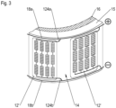
- FIG 3 shows a possible section of a launch vehicle with alternative cable routing which is not part of the claimed subject matter:
- the photovoltaic modules 12' can in turn be inserted into associated recesses, or they can be applied (for example glued) to a smooth area of the surface of the launch vehicle - for example in the form of a solar film, in particular with a thin-film module (not visible).
- the photovoltaic modules 12' each have two connecting lines 124a, 124b, with which they (and thus the majority of solar cells 122) are connected to a respective associated connecting line 18a or 18b.
- the connecting lines 18a, 18b run at least in one section on the outside of the carrier rocket, in particular on an outer surface of the insulation 15, to which they can be glued, for example.
- the Figure 3 The sections shown only partially encircle the launch vehicle in a ring-like manner, and the photovoltaic modules 12' are each arranged between the two connecting lines 18a and 18b, which are spaced apart from one another accordingly.
- the connecting lines 18a, 18b are each connected or to be connected to a pole of at least one electrical and/or electronic component (for example, to a battery); the component can For example, it could be an accumulator that is to be separated from the load and/or part of a load that is or will be transported by the launch vehicle.
- the Figure 3 The embodiment shown is particularly simple to manufacture, especially in the case of photovoltaic modules 12' applied to a smooth surface area as mentioned above, and due to the visibility of the line sections, incorrect connections can be particularly well detected and corrected.
- a launch vehicle 1 for transporting at least one load into an Earth orbit wherein the launch vehicle has a plurality of solar cells 122 on its outer surface 14. Also disclosed are a manufacturing method for a launch vehicle 1 and a transport method for at least one load using a launch vehicle 1.
Landscapes
- Engineering & Computer Science (AREA)
- Remote Sensing (AREA)
- Aviation & Aerospace Engineering (AREA)
- Life Sciences & Earth Sciences (AREA)
- Sustainable Development (AREA)
- Photovoltaic Devices (AREA)
- Chemical & Material Sciences (AREA)
- Combustion & Propulsion (AREA)
Description
- Die vorliegende Erfindung betrifft eine Trägerrakete zum Transport mindestens einer Last in eine Erdumlaufbahn und ein Verfahren zum Transportieren einer Last in eine Erdumlaufbahn.
- Trägerraketen werden in der Raumfahrt dazu verwendet, Lasten wie insbesondere Bauteile oder Versorgungsmaterial für eine Raumstation oder auch Satelliten von der Erdoberfläche in eine vorgesehene Umlaufbahn zu transportieren. Die jeweilige Last ist dabei in der Regel hinter einer Nutzlastverkleidung der Trägerrakete angeordnet und dadurch vor schädigenden Einflüssen während des Starts und/oder Flugs geschützt.
- Die Trägerrakete kann insbesondere als Mehrstufenrakete ausgebildet sein, die während des Flugs sogenannte "untere Stufen" mit leeren Treibstofftanks oder nicht mehr benötigten Triebwerken abwerfen kann, so dass lediglich eine relativ leichte, sogenannte "Oberstufe" der Rakete zur vorgesehenen Umlaufbahn fliegen muss. Aufgrund der Massenreduktion kann auf diese Weise eine höhere Umlaufbahn erreicht werden. Insbesondere kann die Nutzlastverkleidung nach Austritt der Rakete aus der Atmosphäre abzuwerfen sein.
- Die Trägerrakete oder auch eine transportierte Last enthält in der Regel elektrische bzw. elektronische Komponenten, die während des Transportflugs mit elektrischer Energie versorgt werden müssen. Dazu sind gewöhnlich Batterien in der Trägerrakete vorgesehen.
DE10351713 A1 offenbart eine Energieversorgung nach dem Stand der Technik. - Die vorliegende Erfindung hat die Aufgabe, eine verbesserte Technik bereitzustellen, mit der eine Energieversorgung elektrischer und/oder elektronischer Komponenten während eines Transportflugs einer Trägerrakete realisiert werden kann.
- Die Aufgabe wird gelöst durch eine Trägerrakete gemäß Anspruch 1 und ein Transportverfahren gemäß Anspruch 5 zum Transportieren einer Last in eine Erdumlaufbahn. Vorteilhafte Ausführungsformen sind in den Unteransprüchen, der Beschreibung und den Figuren offenbart.
- Eine erfindungsgemäße Trägerrakete dient einem Transport mindestens einer Last (die beispielsweise Versorgungsmaterial oder ein Bauteil für eine Raumstation sein kann oder ein Satellit) in eine Erdumlaufbahn. An ihrer äußeren Oberfläche weist die Trägerrakete eine Mehrzahl an Solarzellen auf.
- Die Mehrzahl an Solarzellen ist in mindestens ein Photovoltaikmodul (die auch als "Solarmodul" oder englisch als "Solarpanels" bezeichnet werden) integriert; ein derartiges Photovoltaikmodul kann mehrere Solarfelder umfassen, in die jeweils mehrere der Solarzellen zusammengefasst sein können. Insbesondere können mehrere der Solarzellen (und/oder ggf. mehrere der Solarfelder) in Reihe geschaltet sein, und/oder mehrere der Solarzellen (bzw. Solarfelder) können parallel geschaltet sein.
- Erfindungsgemäß ist das mindestens eine Photovoltaikmodul in eine Vertiefung in einer Isolierung eingefasst (beispielsweise eingeklebt). Auf diese Weise kann eine besonders solide Befestigung bewirkt werden, zudem können Unebenheiten in der äußeren Oberfläche und damit Luftwiderstände minimiert werden.
- Die äußere Oberfläche, an der die Solarzellen angeordnet sind bzw. werden, ist dann also mindestens teilweise eine Oberfläche der Isolierung, die als Isolationsschicht ausgebildet sein kann. Die Isolierung kann beispielsweise ganz oder teilweise aus Polyurethan (insbesondere Polyurethanschaum) und/oder einem Korkmaterial bestehen.
- Die Isolierung der Trägerrakete kann insbesondere eine Isolierung mindestens eines Treibstofftanks und/oder mindestens einer Übergangsstruktur (die beispielsweise zwischen zwei oder mehr Tanks und/oder Stufen ausgebildet sein kann) der Trägerrakete sein.
- Das mindestens eine Photovoltaikmodul umfasst eine Mehrzahl an Anschlussleitungen, die in einen Kabelbaum gebündelt sind. Ein derartiger Kabelbaum kann mittels eines entsprechenden Anschlusses mit mindestens einer elektrischen und/oder elektronischen Komponente (insbesondere mit einem Akkumulator) der Trägerrakete und/oder einer transportierten Last dauerhaft oder lösbar verbunden sein bzw. werden.
- Gemäß einer vorteilhaften Ausführungsform der vorliegenden Erfindung umfasst die Mehrzahl mindestens eine Solarzelle, die lösbar an eine elektrische und/oder eine elektronische Komponente (beispielsweise einen Akkumulator) der transportierten Last angeschlossen oder anzuschließen ist. Alternativ oder zusätzlich kann die Mehrzahl mindestens eine Solarzelle umfassen, die dauerhaft oder lösbar an mindestens einen Akkumulator angeschlossen oder anzuschließen ist, der seinerseits lösbar mit einer elektrischen und/oder eine elektronischen Komponente der transportierten Last verbunden ist (und der zur Trägerrakete gehörig sein und außerhalb der Last liegen kann). So wird jeweils eine Energieversorgung der elektrischen und/oder eine elektronischen Komponente/n der Last durch die Solarzellen ermöglicht. Insbesondere kann die Last (bzw. deren elektrische und/oder elektronische Komponente/n) damit während der gesamten ballistischen Phase durch die Solarzellen mit Energie versorgt werden.
- Ein Herstellungsverfahren dient der Herstellung einer Trägerrakete, beispielsweise einer erfindungsgemäßen Trägerrakete gemäß einer der in dieser Schrift offenbarten Ausführungsformen. Das Herstellungsverfahren umfasst ein Befestigen einer Mehrzahl an Solarzellen an einer äußeren Oberfläche der Trägerrakete.
- Ein erfindungsgemäßes Transportverfahren umfasst ein Transportieren einer Last mittels einer erfindungsgemäßen Trägerrakete (gemäß einer der in dieser Schrift offenbarten Ausführungsformen) von der Erdoberfläche in eine Erdumlaufbahn.
- Die erfindungsgemäß an der äußeren Oberfläche der Trägerrakete angeordneten Solarzellen ermöglichen eine Aufnahme von Energie in Form von Sonnenlicht und deren Umwandlung in elektrische Energie während des Transportfluges der Trägerrakete. Eine Anzahl an in der Trägerrakete mitzuführenden und für gewöhnlich schweren Batterien kann dadurch vermindert werden, was eine vorteilhafte Massenreduktion bedeutet.
- Die Solarzellen sind bzw. werden vorzugsweise an eine elektrische und/oder elektronische Komponente, insbesondere an mindestens einen Energiespeicher (Akkumulator) der Trägerrakete oder einer mitgeführten Last angeschlossen.
- Ist die Last beispielsweise ein Satellit, der unter Aufwendung elektrischer Energie aufgefaltet und/oder in seine Umlaufbahn geschossen wird, kann die dafür notwendige Energie mindestens teilweise während des Transportfluges durch die Solarzellen gewonnen und in mindestens einem Akkumulator gespeichert werden. Analog kann die für ein Andocken an einer Weltraumstation und/oder für ein Abladen der Last erforderliche Energie und/oder für das Aufrechterhalten eines Bereitschaftsbetriebs mindestens eines mitgeführten Geräts ganz oder teilweise während des Transportfluges durch die Solarzellen gewonnen und/oder in mindestens einem Akkumulator gespeichert werden.
- Gemäß einem speziellen Ausführungsbeispiel eines erfindungsgemäßen Transportverfahrens ist eine transportierte Last ein Satellit und umfasst das Transportverfahren ein Aufladen mindestens eines Akkumulators mittels der Mehrzahl an Solarzellen an der Trägerrakete während des Transports sowie ein Abschießen des Satelliten in die vorgesehene Erdumlaufbahn (insbesondere) mittels elektrischer Energie aus dem Akkumulator.
- Gemäß einer alternativen Variante eines erfindungsgemäßen Transportverfahrens ist eine transportierte Last ein Bauteil oder ein Frachtgut, das zu einer Weltraumstation gebracht wird, und umfasst das Transportverfahren ein Aufladen mindestens eines Akkumulators mittels der Mehrzahl an Solarzellen an der Trägerrakete während des Transports sowie ein Andocken und/oder Abladen des Bauteils bzw. Frachtguts an der Weltraumstation (insbesondere) mittels elektrischer Energie aus dem Akkumulator.
- Vorteilhaft ist eine Ausführungsform der vorliegenden Erfindung, bei der die Trägerrakete als eine Mehrstufenrakete ausgebildet ist und bei der die Mehrzahl an Solarzellen an einer Oberstufe (bezogen auf eine Reihenfolge der Zündung beispielsweise an einer zweiten oder höheren Stufe der Mehrstufenrakete) angeordnet ist bzw. wird. Diese Oberstufe enthält vorzugsweise die zu transportierende Last und fliegt die meiste Zeit des Flugs unter direkter Sonneneinstrahlung.
- Vorteilhaft sind Ausführungsvarianten eines Herstellungsverfahrens, bei denen eine oder mehrere der Solarzellen bei der Herstellung der Oberstufe an deren Oberfläche befestigt wird/werden, und/oder bei denen eine oder mehrere der Solarzellen in einem Montageprozess, in dem zwei oder mehr Stufen der Mehrstufenrakete zusammengesetzt werden, an der Oberfläche der Oberstufe befestigt wird/werden.
- Indem die Solarzellen auftreffende Sonnenergie absorbieren und nicht oder nur teilweise in das dahinter liegende Material weiterleiten, verhindern oder vermindern sie bei diesen Ausführungsvarianten ein unerwünschtes Aufwärmen insbesondere des Treibstoffs im Tank, wirken also als (weitere) Isolierung für den Treibstoff der Trägerrakete. Insbesondere bei kryogenen Treibstoffen ist diese isolierende Funktion besonders vorteilhaft.
- Die äußere Oberfläche, an der die Mehrzahl an Solarzellen angeordnet ist bzw. wird, liegt vorzugsweise in einem im Wesentlichen kreiszylindrisch geformten Abschnitt der Trägerrakete. Insbesondere können die Solarzellen dabei kranzartig um die Trägerrakete herum angeordnet sein. Gemäß einem speziellen Ausführungsbeispiel, bei dem wie erwähnt die Solarzellen in mehrere Photovoltaikmodule integriert sind, können die Photovoltaikmodule (z.B. mindestens teilweise in regelmäßigen Abständen) um die Trägerrakete herum angeordnet sein. Auf diese Weise kann eine Sonneneinstrahlung von verschiedenen Seiten zur Gewinnung elektrischer Energie genutzt werden.
- Die Mehrzahl an Solarzellen kann zusammen eine Einstrahlungsfläche für Sonnenlicht (d.h. eine nutzbare Oberfläche, die also dazu eingerichtet ist, Sonnenlicht zur Energieumwandlung zu absorbieren) von mindestens 10m2, bevorzugter mindestens 20m2 oder sogar mindestens 50m2 umfassen. Auf diese Weise kann ein entsprechend hoher Wirkungsgrad erzielt werden.
- Eine oder mehrere der Solarzellen können als Halbleitermaterial insbesondere mono- oder polykristallines Silizium enthalten.
- Gemäß einer vorteilhaften Ausführungsform ist eine oder sind mehrere der Solarzellen (bzw. - bei entsprechenden Ausführungsformen - ist ein oder sind mehrere der Photovoltaikmodul/e) als biegsame Solarfolie ausgebildet. Derartige Solarfolien sind besonders einfach zu handhaben und an der äußeren Oberfläche der Trägerrakete zu befestigen.
- Eine oder mehrere der Solarzellen (bzw. das/die Photovoltaikmodul/e) kann/können als Dünnschichtmodul/e ausgebildet sein, das bzw. die ein Halbleitermaterial mit einer Schichtdicke von höchstens 2µm oder höchstens 1,5µm umfassen kann/können. Das Halbleitermaterial kann insbesondere auf eine Kunststofffolie aufgebracht, beispielsweise aufgedampft sein bzw. werden: Dies ermöglicht eine einfache Verarbeitung sowie eine vorteilhaft geringe Masse (pro Einstrahlungsfläche).
- Als Halbleitermaterial kann ein derartiges Dünnschichtmodul insbesondere eine oder mehrere Schicht/en aus amorphem und/oder mikrokristallinem Silizium, aus Kupfer-Indium-Gallium-Diselenid (sogenannte "CIS- oder CIGS-Dünnschichtmodule) oder aus Cadmium-Tellurid (CdTe) enthalten.
- Alternativ oder zusätzlich kann/können eine oder mehrere der Solarzellen organisch, also auf Kohlenstoffbasis hergestellt sein, beispielsweise als organische Solarfolie.
- Ein erfindungsgemäßes Transportverfahren kann insbesondere ein Anschließen mindestens einer elektrischen und/oder mindestens einer elektronischen Komponente der transportierten Last an die Solarzellen und/oder an mindestens einen mit den Solarzellen verbundenen Akkumulator umfassen sowie ein Versorgen mindestens der Komponente/n der Last während des Transports mit durch Sonneneinstrahlung auf die Mehrzahl an Solarzellen gewonnener Energie. Das Anschließen erfolgt vorzugsweise vor einem Start der Trägerrakete. Gemäß einer vorteilhaften Ausführungsform umfasst ein erfindungsgemäßes Transportverfahren weiterhin ein Ablösen der jeweilige(n) Komponente(n) der Last von den Solarzellen bzw. von dem mindestens einen mit den Solarzellen verbundenen Akkumulator und danach ein Abladen der Last von der Trägerrakete.
- Im Folgenden wird ein bevorzugtes Ausführungsbeispiel der Erfindung anhand zweier Zeichnungen näher erläutert. Es versteht sich, dass einzelne Elemente und Komponenten auch anders kombiniert werden können als dargestellt. Bezugszeichen für einander entsprechende Elemente sind figurenübergreifend verwendet und werden ggf. nicht für jede Figur neu beschrieben.
- Es zeigen schematisch:
- Figur 1:
- eine Trägerrakete gemäß einer exemplarischen Ausführungsform der vorliegenden Erfindung; und
- Figur 2:
- eine Detailansicht eines möglichen Schichtaufbaus eines Abschnitts der Trägerrakete gemäß
Figur 1 mit einer ersten Leitungsführung; und - Figur 3:
- eine Detailansicht eines Abschnitts einer Trägerrakete mit einer zweiten möglichen Leitungsführung die nicht Teil des beanspruchten Gegenstands ist.
- In
Figur 1 ist eine erfindungsgemäße Trägerrakete 1 gemäß einer exemplarischen Ausführungsform vereinfacht dargestellt. Die Trägerrakete 1 ist als Mehrstufenrakete mit einer Oberstufe 10 und einer lösbaren Antriebsstufe 20 ausgebildet, die ein Triebwerk 21 und davon wiederum lösbare Hilfsraketen (sogenannte "Booster") 22 umfasst. Im Inneren der Oberstufe 10 kann hinter einer Nutzlastverkleidung 11 eine (in der Figur nicht sichtbare) Last wie beispielsweise ein oder mehrere Satellit(en), ein oder mehrere Bauteil(e) für eine Raumstation und/oder Versorgungsmaterial für eine Raumstation von der Erdoberfläche in eine vorgesehene Erdumlaufbahn transportiert werden. - In einem kreiszylindrisch geformten Abschnitt der Oberstufe 10 sind kranzartig um die Trägerrakete 1 herum mehrere Photovoltaikmodule 12 angeordnet.
- In
Figur 2 ist eine Detailansicht einer erfindungsgemäßen Anordnung der Photovoltaikmodule 12 einer Ausführungsvariante der vorliegenden Erfindung dargestellt: Die Photovoltaikmodule 12 umfassen jeweils eine Mehrzahl an teils in Reihe, teils parallel geschalteten Solarfeldern 121, die ihrerseits jeweils eine Mehrzahl an Solarzellen 122 umfassen. Die Photovoltaikmodule 12 sind bzw. werden in zugehörige Vertiefungen 13 in der Oberfläche 14 der Trägerrakete eingesetzt, beispielsweise eingeklebt. Die Vertiefungen 13 sind dabei in eine als Schicht ausgebildete Isolierung 15 an einem Treibstofftank oder an einer Übergangsstruktur 16 eingelassen, von dem in derFigur 2 ein Teil der äußeren Wand sichtbar ist. Die Isolierung 15 verhindert oder vermindert zumindest ein unerwünschtes Aufwärmen des Treibstoffs im Treibstofftank. Die Solarzellen 122, die dazu eingerichtet sind, Sonneneinstrahlung zu absorbieren und in elektrische Energie umzuwandeln, wirken ebenfalls als thermische Isolierung. - Die Solarzellen 122 der einzelnen Photovoltaikmodule 12 weisen jeweils einen gemeinsamen Kabelbaum 123 auf, der dazu eingerichtet ist, mit einem Anschluss 17 in der jeweiligen Vertiefung 13 verbunden zu werden. So kann der von den Solarzellen erzeugte elektrische Strom durch die Isolierung 15 hindurch mittels eines Verbindungskabels einer entsprechenden elektrischen und/oder elektronischen Komponente (insbesondere einem Akkumulator) hinter der Außenwand der Trägerrakete 1 (bzw. der Oberstufe 10) zugeführt werden, so dass beispielsweise eine transportierte Last (bzw. eine elektrische und/oder eine elektronische Komponente der Last) mit der Energie versorgt werden kann. In der in
Figur 2 gezeigten Ausführungsform verläuft das Verbindungskabel hinter der äußeren Oberfläche der Trägerrakete und ist daher in der Figur nicht sichtbar. -
Figur 3 zeigt einen möglichen Abschnitt einer Trägerrakete mit alternativer Leitungsführung die nicht Teil des beanspruchten Gegenstands ist: Die Photovoltaikmodule 12' können dabei wiederum in zugehörige Vertiefungen eingesetzt sein, oder sie können - beispielsweise als Solarfolie, insbesondere mit Dünnschichtmodul ausgebildet - auf einen glatten Bereich der Oberfläche der Trägerrakete aufgebracht (beispielsweise aufgeklebt) sein (nicht sichtbar). - Die Photovoltaikmodule 12' weisen jeweils zwei Anschlussleitungen 124a, 124b auf, mit denen sie (und damit die Mehrzahl an Solarzellen 122) an eine jeweils zugehörige Verbindungsleitung 18a bzw. 18b angeschlossen sind. Die Verbindungsleitungen 18a, 18b verlaufen dabei zumindest in einem Abschnitt an der Außenseite der Trägerrakete, insbesondere an einer Außenfläche der Isolierung 15, auf die sie beispielsweise aufgeklebt sein können. Die in der
Figur 3 lediglich teilweise gezeigten Abschnitte umlaufen dabei ringartig die Trägerrakete, und die Photovoltaikmodule 12' sind jeweils zwischen den beiden Verbindungsleitungen 18a und 18b angeordnet, die entsprechend voneinander beabstandet sind. - Wie exemplarisch durch die Symbole "+" und "-" angedeutet, sind die Verbindungsleitungen 18a, 18b jeweils mit einem Pol mindestens einer elektrischen und/oder elektronischen Komponente (beispielsweise mit einem Akkumulator) verbunden oder zu verbinden; die Komponente kann dabei beispielsweise ein von der Last zu trennender Akkumulator sein und/oder Teil einer von der Trägerrakete transportierten bzw. zu transportierenden Last.
- Die in der
Figur 3 gezeigte Ausführungsform ist besonders einfach herzustellen, insbesondere im Falle von auf einer glatten Oberflächenbereich aufgebrachten Photovoltaikmodulen 12' wie oben genannt, und aufgrund der Sichtbarkeit der Leitungsabschnitte können Fehlanschlüsse besonders gut erkannt und korrigiert werden. - Offenbart ist eine Trägerrakete 1 zum Transport mindestens einer Last in eine Erdumlaufbahn, wobei die Trägerrakete an ihrer äußeren Oberfläche 14 eine Mehrzahl an Solarzellen 122 aufweist. Offenbart sind ferner ein Herstellungsverfahren für eine Trägerrakete 1 und ein Transportverfahren für mindestens eine Last mit einer Trägerrakete 1.
-
- 1
- Trägerrakete
- 10
- Oberstufe
- 11
- Nutzlastverkleidung
- 12, 12'
- Photovoltaikmodul
- 13
- Vertiefung
- 14
- äußere Oberfläche der Trägerrakete
- 15
- Isolierung
- 16
- äußere Oberfläche eines Treibstofftanks oder einer Übergangsstruktur
- 17
- Anschluss
- 18a, 18b
- Verbindungsleitung
- 20
- Antriebsstufe
- 21
- Triebwerk
- 22
- Hilfsraketen ("Booster")
- 121
- Solarfeld
- 122
- Solarzelle
- 123
- Kabelbaum
- 124a, 124b
- Anschlussleitung
Claims (6)
- Trägerrakete (1) zum Transport mindestens einer Last in eine Erdumlaufbahn, wobei die Trägerrakete an ihrer äußeren Oberfläche (14) eine Mehrzahl an Solarzellen (122) aufweist, wobei die Mehrzahl in mindestens ein Photovoltaikmodul (12) integriert ist, das eine Mehrzahl an in einem Kabelbaum (123) gebündelten Anschlussleitungen umfasst und in eine Vertiefung (13) in einer Isolierung (15) eingesetzt ist, und wobei die Mehrzahl an Solarzellen (122)- mindestens eine Solarzelle umfasst, die dazu eingerichtet ist, lösbar an eine elektrische und/oder eine elektronische Komponente einer transportierten bzw. zu transportierenden Last angeschlossen zu werden, wobei der Kabelbaum (123) mittels eines Anschlusses (17) in der Vertiefung (13) mit der elektrischen und/oder elektronischen Komponente zu verbinden ist; und/oder- mindestens einen Akkumulator und mindestens eine Solarzelle umfasst, wobei die Solarzelle dazu eingerichtet ist, lösbar oder dauerhaft an den mindestens einen Akkumulator angeschlossen zu werden, der lösbar mit einer elektrischen und/oder einer elektronischen Komponente der transportierten bzw. zu transportierenden Last zu verbinden ist, wobei der Kabelbaum (123) mittels eines Anschlusses (17) in der Vertiefung (13) mit dem Akkumulator verbunden oder zu verbinden ist.
- Trägerrakete gemäß Anspruch 1, die als eine Mehrstufenrakete ausgebildet ist, wobei die Mehrzahl an Solarzellen an einer Oberstufe (10) der Mehrstufenrakete angeordnet ist.
- Trägerrakete gemäß einem der vorhergehenden Ansprüche, wobei die Mehrzahl an Solarzellen (122) zusammen eine Einstrahlungsoberfläche für Sonnenlicht von mindestens 10m2, bevorzugter mindestens 20m2 oder sogar mindestens 50m2 umfassen.
- Trägerrakete gemäß einem der vorhergehenden Ansprüche, wobei die Mehrzahl an Solarzellen mindestens eine als biegsame Solarfolie ausgebildete und/oder mindestens eine in eine biegsame Solarfolie integrierte und/oder mindestens eine organische Solarzelle umfasst.
- Transportverfahren für mindestens eine Last, wobei die Last mit einer Trägerrakete (1) nach einem der Ansprüche 1 bis 4 von der Erdoberfläche in eine Erdumlaufbahn transportiert wird.
- Transportverfahren nach Anspruch 5, das umfasst:- ein Anschließen mindestens einer elektrischen und/oder mindestens einer elektronischen Komponente der Last an mindestens einen elektrischen Anschluss der Mehrzahl an Solarzellen (122) bzw. einen mit der Mehrzahl an Solarzellen verbundenen Akkumulator und- ein Versorgen der mindestens einen elektrischen bzw. elektronischen Komponente während des Transports mit aus der Mehrzahl an Solarzellen durch Sonneneinstrahlung gewonnener Energie.
Applications Claiming Priority (1)
| Application Number | Priority Date | Filing Date | Title |
|---|---|---|---|
| DE102017126609.7A DE102017126609B4 (de) | 2017-11-13 | 2017-11-13 | Trägerrakete mit Solarzellen, Herstellungsverfahren und Transportverfahren |
Publications (3)
| Publication Number | Publication Date |
|---|---|
| EP3483074A1 EP3483074A1 (de) | 2019-05-15 |
| EP3483074C0 EP3483074C0 (de) | 2024-07-31 |
| EP3483074B1 true EP3483074B1 (de) | 2024-07-31 |
Family
ID=64277503
Family Applications (1)
| Application Number | Title | Priority Date | Filing Date |
|---|---|---|---|
| EP18205255.5A Active EP3483074B1 (de) | 2017-11-13 | 2018-11-08 | Trägerrakete mit solarzellen, herstellungsverfahren und transportverfahren |
Country Status (5)
| Country | Link |
|---|---|
| US (1) | US11597537B2 (de) |
| EP (1) | EP3483074B1 (de) |
| DE (1) | DE102017126609B4 (de) |
| ES (1) | ES2988156T3 (de) |
| NZ (1) | NZ748256A (de) |
Families Citing this family (1)
| Publication number | Priority date | Publication date | Assignee | Title |
|---|---|---|---|---|
| FR3159375A1 (fr) * | 2024-02-15 | 2025-08-22 | Latitude | Procédé et système de communication dans un lanceur spatial et lanceur spatial ainsi équipé |
Citations (1)
| Publication number | Priority date | Publication date | Assignee | Title |
|---|---|---|---|---|
| DE10351713A1 (de) * | 2003-11-05 | 2005-06-23 | Eads Space Transportation Gmbh | Träger für den Transport einer Nutzlast und Verfahren zum Ändern der Umlaufbahn eines Trägers |
Family Cites Families (35)
| Publication number | Priority date | Publication date | Assignee | Title |
|---|---|---|---|---|
| US3204889A (en) * | 1962-08-10 | 1965-09-07 | Robert J Schwinghamer | Space vehicle electrical system |
| US3565719A (en) * | 1967-05-17 | 1971-02-23 | Nasa | Solar panel fabrication |
| US3809337A (en) * | 1969-12-18 | 1974-05-07 | Hughes Aircraft Co | Spin stabilized vehicle and solar cell arrangement therefor |
| US3817477A (en) * | 1971-07-06 | 1974-06-18 | Trw Inc | Deployable annular solar array |
| US3817481A (en) * | 1971-11-17 | 1974-06-18 | Trw Inc | Deployable solar array for a spin stabilized spacecraft |
| US3863870A (en) * | 1972-07-10 | 1975-02-04 | Hughes Aircraft Co | Spin stabilized vehicle and solar cell arrangement therefor |
| US4133501A (en) * | 1975-09-30 | 1979-01-09 | Communications Satellite Corporation | Self-deployable solar cell panel |
| US4554038A (en) * | 1980-08-29 | 1985-11-19 | Trw Inc. | Process for fabricating lightweight, rigid solar array substrate |
| US4768738A (en) * | 1986-10-08 | 1988-09-06 | Friedrich Weinert | Flexible solar skin in combination with an airplane |
| US5006179A (en) * | 1989-05-24 | 1991-04-09 | Solarex Corporation | Interconnect for electrically connecting solar cells |
| US6017000A (en) * | 1998-08-02 | 2000-01-25 | Scott; David R. | Apparatus and methods for in-space satellite operations |
| ATE164814T1 (de) * | 1994-01-28 | 1998-04-15 | Finmeccanica Spa | Strukturaler adapter für den laderaum einer trägerrakete |
| US5683060A (en) * | 1995-06-09 | 1997-11-04 | Iturralde; Miguel A. | Air vehicle |
| US5798574A (en) * | 1996-12-20 | 1998-08-25 | Trw Inc. | Distributed electrical power system for modular spacecraft |
| JP3797871B2 (ja) * | 2000-12-05 | 2006-07-19 | シャープ株式会社 | 宇宙用ソーラーパネルおよびその修理方法 |
| US7093789B2 (en) * | 2004-05-24 | 2006-08-22 | The Boeing Company | Delta-winged hybrid airship |
| WO2005118394A1 (en) * | 2004-06-04 | 2005-12-15 | Intersecure Logic Limited | Propulsion unit for spacecraft, servicing system for providing in-space service operations, and modular spacecraft |
| US20060049301A1 (en) * | 2004-09-08 | 2006-03-09 | Yam Victor Y | Solar-Powered Floatation Device for all types of vehicles (air, land and sea) |
| US7108228B1 (en) * | 2005-02-02 | 2006-09-19 | Manfred Marshall | Hydrogen-fueled spacecraft |
| US8016240B2 (en) * | 2007-03-29 | 2011-09-13 | The Boeing Company | Satellites and satellite fleet implementation methods and apparatus |
| US8459596B2 (en) * | 2009-12-01 | 2013-06-11 | Sunstar IM | Sky/space elevators |
| US8469313B2 (en) * | 2010-02-16 | 2013-06-25 | The Boeing Company | Aerodynamic structure having a ridged solar panel and an associated method |
| DE102011105922A1 (de) * | 2011-06-29 | 2013-01-03 | Airbus Operations Gmbh | Zusatzstromversorgung für Fahrzeuge, insbesondere Luftfahrzeuge |
| US10155598B2 (en) * | 2011-11-05 | 2018-12-18 | Spacedesign Corporation | Commercially feasible method of flying repeated orbital missions using a space vehicle |
| US20190322376A1 (en) * | 2012-02-15 | 2019-10-24 | Microlink Devices, Inc. | High-efficiency, lightweight solar sheets |
| US9957037B2 (en) * | 2013-07-10 | 2018-05-01 | X Development Llc | High altitude aircraft with integrated solar cells, and associated systems and methods |
| IL230180A0 (en) * | 2013-12-26 | 2014-08-31 | Israel Aerospace Ind Ltd | space vehicle |
| US20150287865A1 (en) * | 2014-04-07 | 2015-10-08 | Solaero Technologies Corp. | Parallel interconnection of neighboring solar cells via a common back plane |
| US10263131B2 (en) * | 2014-04-07 | 2019-04-16 | Solaero Technologies Corp. | Parallel interconnection of neighboring solar cells with dual common back planes |
| JP6746573B2 (ja) * | 2014-07-23 | 2020-08-26 | デイヴィッド ハイランド | 宇宙ベースの太陽エネルギを収集及び分配するためのシステム及び方法 |
| US9691926B2 (en) * | 2014-10-02 | 2017-06-27 | X Development Llc | Using solar cells as bypass diode heat sinks |
| US9004410B1 (en) * | 2014-10-24 | 2015-04-14 | Alliance Spacesystems, Llc | Deployable boom for collecting electromagnetic energy |
| US10026857B1 (en) * | 2016-11-23 | 2018-07-17 | Vanguard Space Technologies, Inc. | Assembly and mounting of solar cells on airfoils |
| US20180273170A1 (en) * | 2017-03-21 | 2018-09-27 | Regents Of The University Of Minnesota | Transformable unmanned aerial vehicle |
| WO2020232391A1 (en) * | 2019-05-15 | 2020-11-19 | Ast & Science, Llc | Thermal management system for structures in space |
-
2017
- 2017-11-13 DE DE102017126609.7A patent/DE102017126609B4/de active Active
-
2018
- 2018-11-08 EP EP18205255.5A patent/EP3483074B1/de active Active
- 2018-11-08 ES ES18205255T patent/ES2988156T3/es active Active
- 2018-11-12 NZ NZ74825618A patent/NZ748256A/en unknown
- 2018-11-12 US US16/186,732 patent/US11597537B2/en active Active
Patent Citations (1)
| Publication number | Priority date | Publication date | Assignee | Title |
|---|---|---|---|---|
| DE10351713A1 (de) * | 2003-11-05 | 2005-06-23 | Eads Space Transportation Gmbh | Träger für den Transport einer Nutzlast und Verfahren zum Ändern der Umlaufbahn eines Trägers |
Also Published As
| Publication number | Publication date |
|---|---|
| DE102017126609B4 (de) | 2024-10-10 |
| US20190144144A1 (en) | 2019-05-16 |
| EP3483074C0 (de) | 2024-07-31 |
| EP3483074A1 (de) | 2019-05-15 |
| DE102017126609A1 (de) | 2019-05-16 |
| US11597537B2 (en) | 2023-03-07 |
| ES2988156T3 (es) | 2024-11-19 |
| NZ748256A (en) | 2019-10-25 |
Similar Documents
| Publication | Publication Date | Title |
|---|---|---|
| EP2773556B1 (de) | Höhenluftfahrzeug, luftfahrzeugverband und verfahren zum betreiben eines luftfahrzeugverbands | |
| EP2222562B1 (de) | Brennstoffzellensystemmodul | |
| DE4017438A1 (de) | Sonnenstrahlungsbuendler-kuehlerzusammenbau | |
| DE102011107208A1 (de) | Mobiles Solarsegler-Weltraumkraftwerk und gekoppelte Solarsegler Kraftwerke für weltraumbasierte Energiegewinnung und Erzeugung | |
| EP2935004B1 (de) | Hilfsvorrichtung für hochfliegendes flugzeug | |
| DE102010053371B4 (de) | Mit Strahlungsenergie gespeiste elektrische Energieversorgungseinrichtung sowie Verfahren zum Betreiben einer derartigen Energieversorgungseinrichtung | |
| DE102019208630B4 (de) | Leistungsassistenzsystem zur Unterstützung eines elektrisch antreibbaren, vertikal start- und landefähigen Fluggerätes, Leistungsassistenzeinrichtung und Leistungsassistensverfahren | |
| DE102011100431A1 (de) | Zusatzenergieversorgungsvorrichtung für ein Fahrzeug, insbesondere Fluggerät | |
| DE102011105922A1 (de) | Zusatzstromversorgung für Fahrzeuge, insbesondere Luftfahrzeuge | |
| DE2541536A1 (de) | Solargenerator | |
| DE69612722T2 (de) | Vorrichtung und Verfahren zur Egalisierung der Wärmeableitung zwischen mehreren Radiatoren an einem Raumfahrzeug | |
| DE60013036T2 (de) | Hochfliegender Flugkörper zur Verwendung als Relaisfunkstelle und Verfahren zu seiner Positionierung | |
| DE69409493T2 (de) | Strukturaler Adapter für den Laderaum einer Trägerrakete | |
| DE102017126609B4 (de) | Trägerrakete mit Solarzellen, Herstellungsverfahren und Transportverfahren | |
| DE102013112248B3 (de) | Luftfahrzeug mit einer Brennstoffzelleneinrichtung | |
| DE102018128975A1 (de) | Batteriegehäuse einer Traktionsbatterie | |
| DE102020133854A1 (de) | Tragende Verbundschichtstoffstruktur für ein Luftfahrzeugbauteil, damit hergestelltes Luftfahrzeugbauteil und Luftfahrzeug | |
| DE102014019398A1 (de) | Rückkehrender Starteinrichtung für einen Weltraumrakete und das Startverfahren | |
| DE3722159C2 (de) | ||
| CN108910086B (zh) | 一种基于小卫星星团的可再入式立方星系统 | |
| DE202009010824U1 (de) | Fracht und Personenraumschiff der wiederverwendbaren Nutzung für den Flug zum Mond | |
| EP3970199B1 (de) | Vorrichtung zur umwandlung von licht in elektrische energie | |
| DE102020200194A1 (de) | Drohne mit lösbarer Startenergieversorgung | |
| DE102021111183A1 (de) | Solarbetriebenes Luftfahrzeug | |
| DE202015000135U1 (de) | Rückkehrender Starteinrichtung für einen Weltraumrakete und das Startverfahren |
Legal Events
| Date | Code | Title | Description |
|---|---|---|---|
| PUAI | Public reference made under article 153(3) epc to a published international application that has entered the european phase |
Free format text: ORIGINAL CODE: 0009012 |
|
| STAA | Information on the status of an ep patent application or granted ep patent |
Free format text: STATUS: THE APPLICATION HAS BEEN PUBLISHED |
|
| AK | Designated contracting states |
Kind code of ref document: A1 Designated state(s): AL AT BE BG CH CY CZ DE DK EE ES FI FR GB GR HR HU IE IS IT LI LT LU LV MC MK MT NL NO PL PT RO RS SE SI SK SM TR |
|
| AX | Request for extension of the european patent |
Extension state: BA ME |
|
| STAA | Information on the status of an ep patent application or granted ep patent |
Free format text: STATUS: REQUEST FOR EXAMINATION WAS MADE |
|
| 17P | Request for examination filed |
Effective date: 20191111 |
|
| RBV | Designated contracting states (corrected) |
Designated state(s): AL AT BE BG CH CY CZ DE DK EE ES FI FR GB GR HR HU IE IS IT LI LT LU LV MC MK MT NL NO PL PT RO RS SE SI SK SM TR |
|
| STAA | Information on the status of an ep patent application or granted ep patent |
Free format text: STATUS: EXAMINATION IS IN PROGRESS |
|
| 17Q | First examination report despatched |
Effective date: 20200324 |
|
| P01 | Opt-out of the competence of the unified patent court (upc) registered |
Effective date: 20230612 |
|
| GRAP | Despatch of communication of intention to grant a patent |
Free format text: ORIGINAL CODE: EPIDOSNIGR1 |
|
| STAA | Information on the status of an ep patent application or granted ep patent |
Free format text: STATUS: GRANT OF PATENT IS INTENDED |
|
| INTG | Intention to grant announced |
Effective date: 20240212 |
|
| GRAS | Grant fee paid |
Free format text: ORIGINAL CODE: EPIDOSNIGR3 |
|
| GRAA | (expected) grant |
Free format text: ORIGINAL CODE: 0009210 |
|
| STAA | Information on the status of an ep patent application or granted ep patent |
Free format text: STATUS: THE PATENT HAS BEEN GRANTED |
|
| AK | Designated contracting states |
Kind code of ref document: B1 Designated state(s): AL AT BE BG CH CY CZ DE DK EE ES FI FR GB GR HR HU IE IS IT LI LT LU LV MC MK MT NL NO PL PT RO RS SE SI SK SM TR |
|
| REG | Reference to a national code |
Ref country code: CH Ref legal event code: EP Ref country code: GB Ref legal event code: FG4D Free format text: NOT ENGLISH |
|
| REG | Reference to a national code |
Ref country code: DE Ref legal event code: R096 Ref document number: 502018014932 Country of ref document: DE |
|
| REG | Reference to a national code |
Ref country code: IE Ref legal event code: FG4D Free format text: LANGUAGE OF EP DOCUMENT: GERMAN |
|
| U01 | Request for unitary effect filed |
Effective date: 20240812 |
|
| U07 | Unitary effect registered |
Designated state(s): AT BE BG DE DK EE FI FR IT LT LU LV MT NL PT SE SI Effective date: 20240827 |
|
| P04 | Withdrawal of opt-out of the competence of the unified patent court (upc) registered |
Free format text: CASE NUMBER: APP_48406/2024 Effective date: 20240822 |
|
| REG | Reference to a national code |
Ref country code: ES Ref legal event code: FG2A Ref document number: 2988156 Country of ref document: ES Kind code of ref document: T3 Effective date: 20241119 |
|
| U20 | Renewal fee for the european patent with unitary effect paid |
Year of fee payment: 7 Effective date: 20241126 |
|
| P05 | Withdrawal of opt-out of the competence of the unified patent court (upc) changed |
Free format text: CASE NUMBER: APP_48406/2024 Effective date: 20240827 |
|
| PG25 | Lapsed in a contracting state [announced via postgrant information from national office to epo] |
Ref country code: NO Free format text: LAPSE BECAUSE OF FAILURE TO SUBMIT A TRANSLATION OF THE DESCRIPTION OR TO PAY THE FEE WITHIN THE PRESCRIBED TIME-LIMIT Effective date: 20241031 |
|
| PG25 | Lapsed in a contracting state [announced via postgrant information from national office to epo] |
Ref country code: PL Free format text: LAPSE BECAUSE OF FAILURE TO SUBMIT A TRANSLATION OF THE DESCRIPTION OR TO PAY THE FEE WITHIN THE PRESCRIBED TIME-LIMIT Effective date: 20240731 Ref country code: GR Free format text: LAPSE BECAUSE OF FAILURE TO SUBMIT A TRANSLATION OF THE DESCRIPTION OR TO PAY THE FEE WITHIN THE PRESCRIBED TIME-LIMIT Effective date: 20241101 |
|
| PG25 | Lapsed in a contracting state [announced via postgrant information from national office to epo] |
Ref country code: IS Free format text: LAPSE BECAUSE OF FAILURE TO SUBMIT A TRANSLATION OF THE DESCRIPTION OR TO PAY THE FEE WITHIN THE PRESCRIBED TIME-LIMIT Effective date: 20241130 |
|
| PG25 | Lapsed in a contracting state [announced via postgrant information from national office to epo] |
Ref country code: HR Free format text: LAPSE BECAUSE OF FAILURE TO SUBMIT A TRANSLATION OF THE DESCRIPTION OR TO PAY THE FEE WITHIN THE PRESCRIBED TIME-LIMIT Effective date: 20240731 |
|
| PG25 | Lapsed in a contracting state [announced via postgrant information from national office to epo] |
Ref country code: RS Free format text: LAPSE BECAUSE OF FAILURE TO SUBMIT A TRANSLATION OF THE DESCRIPTION OR TO PAY THE FEE WITHIN THE PRESCRIBED TIME-LIMIT Effective date: 20241031 |
|
| PG25 | Lapsed in a contracting state [announced via postgrant information from national office to epo] |
Ref country code: RS Free format text: LAPSE BECAUSE OF FAILURE TO SUBMIT A TRANSLATION OF THE DESCRIPTION OR TO PAY THE FEE WITHIN THE PRESCRIBED TIME-LIMIT Effective date: 20241031 Ref country code: PL Free format text: LAPSE BECAUSE OF FAILURE TO SUBMIT A TRANSLATION OF THE DESCRIPTION OR TO PAY THE FEE WITHIN THE PRESCRIBED TIME-LIMIT Effective date: 20240731 Ref country code: NO Free format text: LAPSE BECAUSE OF FAILURE TO SUBMIT A TRANSLATION OF THE DESCRIPTION OR TO PAY THE FEE WITHIN THE PRESCRIBED TIME-LIMIT Effective date: 20241031 Ref country code: IS Free format text: LAPSE BECAUSE OF FAILURE TO SUBMIT A TRANSLATION OF THE DESCRIPTION OR TO PAY THE FEE WITHIN THE PRESCRIBED TIME-LIMIT Effective date: 20241130 Ref country code: HR Free format text: LAPSE BECAUSE OF FAILURE TO SUBMIT A TRANSLATION OF THE DESCRIPTION OR TO PAY THE FEE WITHIN THE PRESCRIBED TIME-LIMIT Effective date: 20240731 Ref country code: GR Free format text: LAPSE BECAUSE OF FAILURE TO SUBMIT A TRANSLATION OF THE DESCRIPTION OR TO PAY THE FEE WITHIN THE PRESCRIBED TIME-LIMIT Effective date: 20241101 |
|
| PG25 | Lapsed in a contracting state [announced via postgrant information from national office to epo] |
Ref country code: SM Free format text: LAPSE BECAUSE OF FAILURE TO SUBMIT A TRANSLATION OF THE DESCRIPTION OR TO PAY THE FEE WITHIN THE PRESCRIBED TIME-LIMIT Effective date: 20240731 |
|
| PG25 | Lapsed in a contracting state [announced via postgrant information from national office to epo] |
Ref country code: CZ Free format text: LAPSE BECAUSE OF FAILURE TO SUBMIT A TRANSLATION OF THE DESCRIPTION OR TO PAY THE FEE WITHIN THE PRESCRIBED TIME-LIMIT Effective date: 20240731 |
|
| PG25 | Lapsed in a contracting state [announced via postgrant information from national office to epo] |
Ref country code: SK Free format text: LAPSE BECAUSE OF FAILURE TO SUBMIT A TRANSLATION OF THE DESCRIPTION OR TO PAY THE FEE WITHIN THE PRESCRIBED TIME-LIMIT Effective date: 20240731 |
|
| PLBE | No opposition filed within time limit |
Free format text: ORIGINAL CODE: 0009261 |
|
| STAA | Information on the status of an ep patent application or granted ep patent |
Free format text: STATUS: NO OPPOSITION FILED WITHIN TIME LIMIT |
|
| PG25 | Lapsed in a contracting state [announced via postgrant information from national office to epo] |
Ref country code: MC Free format text: LAPSE BECAUSE OF FAILURE TO SUBMIT A TRANSLATION OF THE DESCRIPTION OR TO PAY THE FEE WITHIN THE PRESCRIBED TIME-LIMIT Effective date: 20240731 |
|
| 26N | No opposition filed |
Effective date: 20250501 |
|
| PG25 | Lapsed in a contracting state [announced via postgrant information from national office to epo] |
Ref country code: IE Free format text: LAPSE BECAUSE OF NON-PAYMENT OF DUE FEES Effective date: 20241108 |
|
| PG25 | Lapsed in a contracting state [announced via postgrant information from national office to epo] |
Ref country code: RO Free format text: LAPSE BECAUSE OF FAILURE TO SUBMIT A TRANSLATION OF THE DESCRIPTION OR TO PAY THE FEE WITHIN THE PRESCRIBED TIME-LIMIT Effective date: 20240731 |
|
| REG | Reference to a national code |
Ref country code: CH Ref legal event code: U11 Free format text: ST27 STATUS EVENT CODE: U-0-0-U10-U11 (AS PROVIDED BY THE NATIONAL OFFICE) Effective date: 20251201 |
|
| U20 | Renewal fee for the european patent with unitary effect paid |
Year of fee payment: 8 Effective date: 20251127 |
|
| PGFP | Annual fee paid to national office [announced via postgrant information from national office to epo] |
Ref country code: GB Payment date: 20251121 Year of fee payment: 8 |
|
| PGFP | Annual fee paid to national office [announced via postgrant information from national office to epo] |
Ref country code: CH Payment date: 20251201 Year of fee payment: 8 |
|
| PGFP | Annual fee paid to national office [announced via postgrant information from national office to epo] |
Ref country code: ES Payment date: 20251229 Year of fee payment: 8 |
|
| PG25 | Lapsed in a contracting state [announced via postgrant information from national office to epo] |
Ref country code: HU Free format text: LAPSE BECAUSE OF FAILURE TO SUBMIT A TRANSLATION OF THE DESCRIPTION OR TO PAY THE FEE WITHIN THE PRESCRIBED TIME-LIMIT; INVALID AB INITIO Effective date: 20181108 |
|
| PG25 | Lapsed in a contracting state [announced via postgrant information from national office to epo] |
Ref country code: CY Free format text: LAPSE BECAUSE OF FAILURE TO SUBMIT A TRANSLATION OF THE DESCRIPTION OR TO PAY THE FEE WITHIN THE PRESCRIBED TIME-LIMIT; INVALID AB INITIO Effective date: 20181108 |