EP3482982B1 - Dachspriegel für ein kraftfahrzeug mit einem faltverdeck sowie verfahren zur herstellung eines dachspriegels - Google Patents
Dachspriegel für ein kraftfahrzeug mit einem faltverdeck sowie verfahren zur herstellung eines dachspriegels Download PDFInfo
- Publication number
- EP3482982B1 EP3482982B1 EP18203712.7A EP18203712A EP3482982B1 EP 3482982 B1 EP3482982 B1 EP 3482982B1 EP 18203712 A EP18203712 A EP 18203712A EP 3482982 B1 EP3482982 B1 EP 3482982B1
- Authority
- EP
- European Patent Office
- Prior art keywords
- component
- roof
- components
- roof arch
- region
- Prior art date
- Legal status (The legal status is an assumption and is not a legal conclusion. Google has not performed a legal analysis and makes no representation as to the accuracy of the status listed.)
- Active
Links
Images

Classifications
-
- B—PERFORMING OPERATIONS; TRANSPORTING
- B60—VEHICLES IN GENERAL
- B60J—WINDOWS, WINDSCREENS, NON-FIXED ROOFS, DOORS, OR SIMILAR DEVICES FOR VEHICLES; REMOVABLE EXTERNAL PROTECTIVE COVERINGS SPECIALLY ADAPTED FOR VEHICLES
- B60J7/00—Non-fixed roofs; Roofs with movable panels, e.g. rotary sunroofs
- B60J7/08—Non-fixed roofs; Roofs with movable panels, e.g. rotary sunroofs of non-sliding type, i.e. movable or removable roofs or panels, e.g. let-down tops or roofs capable of being easily detached or of assuming a collapsed or inoperative position
- B60J7/12—Non-fixed roofs; Roofs with movable panels, e.g. rotary sunroofs of non-sliding type, i.e. movable or removable roofs or panels, e.g. let-down tops or roofs capable of being easily detached or of assuming a collapsed or inoperative position foldable; Tensioning mechanisms therefor, e.g. struts
- B60J7/1226—Soft tops for convertible vehicles
- B60J7/1234—Soft tops for convertible vehicles characterised by arches, e.g. shape or material
- B60J7/1243—Intermediate bows
Definitions
- the present invention relates to a roof bow for a motor vehicle with a folding top, the roof bow being connectable to the folding top, which is movable between a closed position and an open position, the roof bow extending transversely to the direction of travel of the vehicle in the installed position.
- the invention further relates to a method for producing the roof bow.
- Roof bars for a motor vehicle with a folding top are from the EP 2 719 563 B1 is known, the roof bow having a first component made as a hollow profile made of a light metal and two second components made of steel.
- the first component here has a geometry which gives the folding top a shape which is substantially cambered transversely to the direction of travel of the vehicle.
- the second components are designed as handlebars for connection to the body and are overmolded with a plastic. Since the second component of the roof bow is installed in the area of the head impact for passengers, it is necessary to provide appropriate radii to protect against possible head injuries as a result of an accident.
- Multi-part roof bows which have a central area made of a first material and side fittings made of a more rigid material, are also from the WO 2005/039908 A1 known.
- the fittings hold the roof hoops on the frame parts of the folding top and are connected to the roof hoops by means of fasteners which, when the folding top is closed, are approximately parallel to the extension plane of the outer roof covering in the area of the roof hoop.
- a roof bow for a motor vehicle with a folding roof the roof bow being connectable to the folding roof, which can be moved between a closed position and an open position, the roof bow running in the installed position transverse to the direction of travel of the vehicle, the roof bow consists of a first component, which in the installed position essentially transversely to the direction of travel of the vehicle and two second components which are designed as links and two third components which are designed as end caps, the first component consisting of at least a first material and the second component consists of a second and the third component made of a third material different from the first and second component, and wherein the first component is designed on its underside with radii to meet the head impact law.
- This design makes it possible to use different materials in a targeted manner according to the requirements and load of the component and to achieve a considerable weight reduction with high strength at the same time.
- “Different materials” is understood here to mean that the respective base bodies of the two components consist of different materials. However, it is possible that further parts used in the components, which for example fulfill a function in the connection or transmission of forces, have the same or similar base material as the other component.
- the roof bow comprises a first component, the first component being designed as a hollow profile.
- the first component can then be cut according to a required length.
- the first component has a geometry such that a folding top has a shape which is substantially cambered transversely to the direction of travel of the vehicle.
- the first component is made of light metal, preferably aluminum or an aluminum alloy.
- Aluminum has the advantage that it is considerably lighter than steel and is preferably used for the production of extruded profiles, which means that the first component can be manufactured inexpensively with low weight and sufficient rigidity.
- the hollow profile is also conceivable for the hollow profile to be produced by another method, for example by hydroforming (IHU) or by roll forming.
- the second component has a steel base body, which is a bent stamped part.
- the steel base body is essentially a flat steel, which is manufactured according to the requirements.
- the component can be geometrically adapted to the requirements in a simple manner by means of bending punching.
- the geometry of the component is designed such that it can ideally absorb or transmit the forces acting on the component.
- the second component is designed as a handlebar, as is known in the prior art for folding tops.
- Handlebars have the task of connecting a roof bow to the body and are part of a roof kinematics system that is required to open and close a folding top.
- Handlebars are arranged to the left and right of a roof bow and are connected, for example, to a further handlebar arrangement or to a guideway of the roof kinematics, which is arranged in the fixed roof part of the vehicle.
- radii are called head impact radii and must be at least 3 mm in the interior of a motor vehicle according to laws and regulations (FMVSS 201 and ECE R-21). According to the invention, these radii are designed on the first component.
- a corresponding depression is formed between the radii.
- the second component is placed over a section of the first component and permanently connected to the first component in this area.
- the third component is permanently connected to the first component via a connecting section.
- the third component is designed as a roof bow end cap made of a plastic.
- the material of the third component is advantageously an elastomer. This design has the advantage that the corners of the bow end caps can nestle tangentially to the convertible top cover, thereby avoiding marks on the roof bow from the outside of the convertible top cover.
- the inventive configuration of the permanent connection between the components described enables better securing of the third component on the first component.
- the specified design and arrangement of the components leads to an installation space advantage in the storage position of the folding top.
- the method according to the invention forms a unit which can be connected to the body of a motor vehicle.
- the manufacture and assembly of the roof bow leads to cost and time savings. This is due, among other things, to the fact that the head impact radii are designed on the first component and the handlebar does not require any additional plastic extrusion for attachment to the first component.
- the permanent connection is preferably a riveted connection, which can include a positive as well as a combined positive and non-positive connection.
- Fig. 1 shows a perspective side view of the top components of a folding top 1 for a convertible vehicle in the closed position.
- the vehicle's longitudinal direction or direction of travel is indicated by the arrow F.
- the folding top 1 can be moved into a folded storage position between a closed position spanning a passenger compartment.
- the folding top 1 has a top cover which is carried by the top components.
- the convertible top cover is essentially supported in the transverse direction Q by roof brackets 2; the convertible top cover is not shown in the drawing in FIG. 1.
- the adjustable folding top 1 extends from a windshield frame (not shown) arranged on the front V into a rear area H of the vehicle.
- the folding top 1 is constructed symmetrically with respect to a central axis A.
- FIG. 2 A roof bow 2 according to the invention is shown, which essentially consists of a first component 3, two second components 4 and two third components 5, which are permanently connected to one another.
- the roof bows 2 of the folding top 1 are constructed symmetrically with respect to the central axis A, wherein a second and a third component 4, 5 are arranged and fastened at the end-formed sections on the first component 3. The assembly and the corresponding fastening are described with the other figures.
- the first component 3 is shown, which is essentially a hollow profile 3.1, which is produced by extrusion.
- the hollow profile 3.1 is made of light metal, preferably aluminum or an aluminum alloy.
- An example of a possible material is an aluminum material called EN AW-6060 T6.
- the first component 3 has a geometry such that a folding top has a shape which is substantially cambered transversely to the direction of travel of the vehicle.
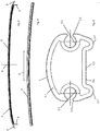
- the first component 3 is in the Figure 4 shown in a cross section. From this illustration it can be seen that the first component 3 has channels 3.2 running on both sides in the transverse direction Q for introducing connecting elements for the convertible top material. These channels 3.2 each have a slot 3.3 and a circular cross section 3.4. On the underside 3.5 of the first component 3, a depression 3.6 running in the transverse direction is formed, which is delimited by radii 3.7 on the edge. The depression 3.6 serves for the connection of the second component 4 during the assembly of the roof bow. The radii 3.7 formed at the edge areas form the head impact radii in order to fulfill the legal requirements of the head impact law.
- Fig. 6 shows a steel base body 4.1 of the second component 4.
- the steel base body 4.1 is a bent stamped part, and has approximately an L-shape, which comprises two plate-shaped elements 4.2, 4.3. At least two through bores 4.4 are provided in the one plate-shaped element 4.3, which can be connected to the first component 3 and the third component 5, which allows the first component 3 to be permanently connected to the second and third component 4.
- the second component is designed as a handlebar for folding roofs and represents the connection of the roof bow 2 to the body as part of the roof kinematics.
- the third component 5 is shown in a perspective view.
- the third component 5 is made of a plastic as an injection molded part and comprises two areas.
- the first area 5.1 is designed as a connecting section with fastening ribs 5.2 and its cross section is adapted to the cross section of the hollow profile 3.1.
- a cavity 5.4 remains between the fastening ribs 5.2.
- the third component 5 with the first area 5.1 is inserted into the hollow profile 3.1 of the first component.
- the third component 5 projects with its second region 5.3 out of the first component 1.
- the course and the curvature of the second region 5.3 are adapted to the first component 1, so that the third component 5 has a plastic end cap for the roof bow 1 forms, the end cap tapers towards the outside of the roof bow 1 in its cross section.
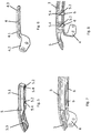
- FIGS. 7 and 8 show an end region of the roof bow in the assembled state, the first, second and third component being permanently connected to one another via a rivet connection 6.
- a third component 5 and a second component 4 are fastened to the end regions on both sides, as described below.
- the following description only relates to the assembly at one end area, the assembly being carried out equally at the second end area.
- the third component 5 is inserted into the hollow profile 3.1 of the roof bow 2 by means of the first region 5.1 in a first step. Furthermore, the second component 4 is placed in the depression 3.6 by means of the plate-shaped element 4.3, the through bores 4.4 of the second component being aligned with the cavities 5.4 between the fastening ribs 5.2. In a final assembly step, the first, second and third components 3, 4, 5 are riveted together with blind rivets 6. The second component is fixed to the first component by riveting. Furthermore, the third component 5 is fixed to the first component 3 in the region of the fastening ribs.
Landscapes
- Engineering & Computer Science (AREA)
- Mechanical Engineering (AREA)
- Body Structure For Vehicles (AREA)
Description
- Die vorliegende Erfindung betrifft einen Dachspriegel für ein Kraftfahrzeug mit einem Faltverdeck, wobei der Dachspriegel mit dem Faltverdeck, welches zwischen einer Schließstellung und einer Offenstellung bewegbar ist, verbindbar ist, wobei der Dachspriegel in Einbaulage quer zur Fahrtrichtung des Fahrzeugs verläuft. Die Erfindung betrifft weiterhin ein Verfahren zur Herstellung des Dachspriegels.
- Dachspriegel für ein Kraftfahrzeug mit einem Faltverdeck sind aus der
EP 2 719 563 B1 bekannt, wobei die Dachspriegel ein erstes als Hohlprofil aus einem Leichtmetall ausgeführtes Bauteil und zwei zweite Bauteile aus Stahl aufweisen. Das erste Bauteil weist hierbei eine Geometrie auf, die dem Faltverdeck einen Formenverlauf gibt, welcher quer zur Fahrtrichtung des Fahrzeugs im Wesentlichen bombiert ist. Die zweiten Bauteile sind als Lenker zur Anbindung an die Karosserie ausgeführt und sind mit einem Kunststoff umspritzt. Da sich das zweite Bauteil des Dachspriegels im verbauten Zustand im Bereich des Kopfaufschlags für Passagiere befindet, ist es zum Schutz vor möglichen Kopfverletzungen in Folge eines Unfalls erforderlich, entsprechende Radien vorzusehen. Diese Radien werden als Kopfaufprallradien bezeichnet und müssen bei der Umspritzung im Bereich des als Lenkers ausgeführten zweiten Bauteils entsprechend berücksichtigt werden. Bei der Montage der Dachspriegel werden die Umspritzungsbereiche der zweiten Bauteile in das Hohlprofil des ersten Bauteils eingesteckt und in einem weiteren Schritt werden die Bauteile durch Verpressen dauerhaft miteinander verbunden. - Mehrteilige Dachspriegel, die einen Mittenbereich aus einem ersten Material und seitliche Beschläge aus einem biegefesteren anderen Material aufweisen, sind weiterhin aus der
WO 2005/039908 A1 bekannt. Die Beschläge halten dabei die Dachspriegel an den Rahmenteilen des Faltverdecks und sind über Befestigungsmittel, die bei geschlossenem Faltverdeck annähernd parallel zur Erstreckungsebene des äußeren Dachbezugs im Bereich des Dachspriegels liegen, mit den Dachspriegeln verbunden. - Es ist eine Aufgabe der Erfindung, einen Dachspriegel zu verbessern, so dass bei der Fertigung einerseits Kosten reduziert werden und andererseits Zeit eingespart werden kann, wobei der hergestellte Dachspriegel einen geringen Bauraum in der Ablageposition des Faltverdecks benötigt und ein geringes Gewicht aufweist und zwischen den Bauteilen des Dachspriegels eine sichere Verbindung besteht.
- Die Lösung der Aufgabe erfolgt durch einen Dachspriegel für ein Kraftfahrzeug mit einem Faltverdeck, wobei der Dachspriegel mit dem Faltdach, welches zwischen einer Schließstellung und einer Offenstellung bewegbar ist, verbindbar ist, wobei der Dachspriegel in Einbaulage quer zur Fahrtrichtung des Fahrzeugs verläuft, wobei der Dachspriegel aus einem ersten Bauteil, welches in Einbaulage im Wesentlichen quer zur Fahrtrichtung des Fahrzeugs und zwei zweite Bauteilen welche als Lenker ausgebildet sind und zwei dritten Bauteilen welche als Endkappen ausgebildet sind, besteht, wobei das erste Bauteil zumindest aus einem ersten Material besteht und das zweite Bauteil aus einem zweiten und das dritte Bauteil aus einem dritten Material vom ersten und zweiten Bauteil verschiedenen Material besteht, und wobei das erste Bauteil an seiner Unterseite mit Radien zur Erfüllung der Kopfaufschlaggesetzes ausgeführt ist.
- Diese Ausführung ermöglicht es, unterschiedliche Materialien, entsprechend der Anforderung und Belastung des Bauteils gezielt zu nutzen und eine erhebliche Gewichtsreduktion bei gleichzeitig hoher Festigkeit zu erreichen.
- Unter "verschiedenen Materialen" wird hierbei verstanden, dass die jeweiligen Grundkörper der beiden Bauteile aus verschiedenen Materialien bestehen. Es ist jedoch möglich, dass in die Bauteile eingesetzte weitere Teile, welche beispielsweise eine Funktion bei der Verbindung oder Übertragung von Kräften erfüllen, ein gleiches oder ähnliches Grundmaterial aufweisen, wie das jeweils andere Bauteil.
- Erfindungsgemäß umfasst der Dachspriegel ein erstes Bauteil, wobei das erste Bauteil als Hohlprofil ausgeführt ist. Das erste Bauteil kann dann entsprechend einer erforderlichen Länge abgeschnitten werden. Das erste Bauteil weist eine Geometrie auf, dass es einem Faltverdeck einen Formverlauf gibt, welcher quer zur Fahrtrichtung des Fahrzeugs im Wesentlichen bombiert ist. Das erste Bauteil ist aus Leichtmetall, bevorzugt aus Aluminium oder einer Aluminiumlegierung, hergestellt.
- Aluminium bietet den Vorteil, dass es wesentlich leichter als Stahl ist, und wird bevorzugt zur Herstellung von Strangpressprofilen eingesetzt, wodurch das erste Bauteil kostengünstig bei niedrigem Gewicht und ausreichender Steifigkeit hergestellt werden kann.
- Alternativ zum Strangpressziehen ist es auch denkbar, dass die Herstellung des Hohlprofils durch ein anderes Verfahren, beispielsweise durch Innenhochdruckumformen (IHU) oder durch Rollformen, erfolgt.
- Das zweite Bauteil weist einen Stahlgrundkörper auf, welcher ein Biege-Stanzteil ist. Der Stahlgrundkörper ist dabei im Wesentlichen ein Flachstahl, welcher entsprechend den Erfordernissen gefertigt wird. Durch Biege-Stanzen kann das Bauteil in einfacher Weise geometrisch den Anforderungen angepasst werden. Die Geometrie des Bauteils ist dabei so ausgestaltet, dass es die auf das Bauteil wirkenden Kräfte ideal aufnehmen bzw. übertragen kann.
- Das zweite Bauteil ist als Lenker ausgeführt, wie es im Stand der Technik für Faltverdecke bekannt ist. Lenker haben die Aufgabe einen Dachspriegel mit der Karosserie zu verbinden und sind ein Teil einer Dachkinematik, welche für das Öffnen und Schließen eines Faltverdecks erforderlich ist. Lenker werden links und rechts eines Dachspriegels angeordnet und sind beispielsweise mit einer weiteren Lenkeranordnung oder mit einer Führungsbahn der Dachkinematik, welche im festen Dachteil des Fahrzeugs angeordnet ist, verbunden.
- Da sich der Dachspriegels im verbauten Zustand im Bereich des Kopfaufschlags für Passagiere befindet, ist es erforderlich zum Schutz vor möglichen Kopfverletzungen in Folge eines Unfalls, entsprechende Radien an den Kanten der betroffenen Bauteile vorzusehen. Diese Radien werden als Kopfaufprallradien bezeichnet und müssen nach Gesetzen und Vorschriften (FMVSS 201 und ECE R-21) im Innenraum eines Kraftfahrzeugs zumindest 3mm betragen. Diese Radien sind erfindungsgemäß am ersten Bauteil ausgeführt.
- Zwischen den Radien ist eine entsprechende Einsenkung ausgebildet. Im Bereich der Einsenkung wird das zweite Bauteil über einen Abschnitt an das erste Bauteil angelegt und in diesem Bereich mit dem ersten Bauteil dauerhaft verbunden. Des Weiteren wird das dritte Bauteil über einen Verbindungsabschnitt mit dem ersten Bauteil dauerhaft verbunden.
- Das dritte Bauteil ist als Dachspriegelendkappe aus einem Kunststoff ausgeführt. Vorteilhafterweise ist das Material des dritten Bauteils ein Elastomer. Durch diese Ausführung ergibt sich der Vorteil, dass sich die Ecken der Spriegelendkappen tangential an den Verdeckbezug schmiegen können und dadurch Abzeichnungen der Dachspriegel von außen am Verdeckbezug vermeiden lassen.
- Durch die erfindungsgemäße Ausgestaltung der beschriebenen dauerhaften Verbindung zwischen den Bauteilen ist eine bessere Sicherung des dritten Bauteils am ersten Bauteil möglich.
- Die angegebene Ausführung und Anordnung der Bauteile führt zu einem Bauraumvorteil in der Ablageposition des Faltverdecks.
- Durch das erfindungsgemäße Verfahren wird eine Einheit gebildet, welche mit der Karosserie eines Kraftfahrzeugs verbunden werden kann. Die Herstellung und Montage der Dachspriegel führt zu einer Kosten- und Zeiteinsparung. Dies ist unter anderem dadurch bedingt, dass die Kopfaufschlagradien an dem ersten Bauteil ausgeführt sind und der Lenker keine zusätzliche Kunststoffumspritzung zur Befestigung am ersten Bauteil benötigt.
- Die dauerhafte Verbindung ist vorzugsweise eine Nietverbindung, die eine formschlüssige als auch eine kombinierte form- und kraftschlüssige Verbindung umfassen kann.
- Die Erfindung wird nachfolgend anhand eines in den Zeichnungen schematisch dargestellten Ausführungsbeispiels beschrieben.
- Es zeigt:
-
Fig. 1 eine perspektivische Ansicht eines Faltverdecks für ein Kraftfahrzeug in der Schließstellung, -
Fig. 2 einen Zusammenbau des erfindungsgemäßen Dachspriegels, -
Fig. 3 ein erstes Bauteil des erfindungsgemäßen Dachspriegels in einer Ansicht, -
Fig. 4 das erste Bauteil in einem Querschnitt, -
Fig. 5 eine perspektivische Ansicht eines zweiten Bauteils eines Dachspriegels, -
Fig. 6 eine perspektivische Ansicht eines dritten Bauteils eines Dachspriegels, -
Fig. 7 eine perspektivische Ansicht eines Ausschnitts gemäß Detail A inFigur 4 ; und -
Fig. 8 einen Schnitt des Ausschnitts derFigur 7 . -
Fig. 1 zeigt in einer perspektivischen Seitenansicht die Verdeckbauteile eines Faltverdecks 1 für ein Cabriolet-Fahrzeug in Schließposition. Die Fahrzeuglängsrichtung bzw. Fahrtrichtung ist mit dem Pfeil F angezeigt. Das Faltverdeck 1 kann zwischen einer einen Fahrgastraum überspannenden Schließstellung in eine zusammengefaltete Ablagestellung bewegt werden. Das Faltverdeck 1 weist einen Verdeckbezug auf, der von den Verdeckbauteilen getragen ist. Der Verdeckbezug wird in Querrichtung Q im Wesentlichen von Dachspriegeln 2 gestützt, der Verdeckbezug ist zeichnerisch in der Figur 1 nicht dargestellt. Das verstellbare Faltverdeck 1 erstreckt sich ausgehend von einem auf der Vorderseite V angeordneten nicht dargestellten Windschutzscheibenrahmen in einen Heckbereich H des Fahrzeugs. Das Faltverdeck 1 ist bezogen auf eine Mittelachse A symmetrisch aufgebaut. - In
Fig. 2 ist ein erfindungsgemäßer Dachspriegel 2 dargestellt, welcher im Wesentlichen aus einem ersten Bauteil 3, zwei zweiten Bauteilen 4 und zwei dritten Bauteilen 5 besteht, welche dauerhaft miteinander verbunden sind. Die Dachspriegel 2 des Faltverdecks 1 sind in Bezug auf die Mittelachse A symmetrisch aufgebaut, wobei jeweils an endseitig ausgebildeten Abschnitten an dem ersten Bauteil 3 ein zweites und ein drittes Bauteil 4, 5 angeordnet und befestigt sind. Der Zusammenbau und die entsprechende Befestigung werden zu den weiteren Figuren beschrieben. - In
Fig. 3 wird das erste Bauteil 3 dargestellt, welches im Wesentlichen ein Hohlprofil 3.1 ist, das durch Strangpressziehen hergestellt wird. Das Hohlprofil 3.1 wird aus Leichtmetall, bevorzugt Aluminium oder eine Aluminiumlegierung, hergestellt. Ein Beispiel eines möglichen Materials ist ein Aluminiumwerkstoff mit der Bezeichnung EN AW-6060 T6. Das erste Bauteil 3 weist eine Geometrie auf, dass es einem Faltverdeck einen Formverlauf gibt, welcher quer zur Fahrtrichtung des Fahrzeugs im Wesentlichen bombiert ist. - Das erste Bauteil 3 ist in der
Figur 4 in einem Querschnitt dargestellt. Aus dieser Darstellung kann man erkennen, dass das erste Bauteil 3 beidseits in Querrichtung Q verlaufende Kanäle 3.2 zum Einführen von Anbindungselementen für den Verdeckstoff aufweist. Diese Kanäle 3.2 weisen jeweils einen Schlitz 3.3 und einen kreisförmigen Querschnitt 3.4 auf. Auf der Unterseite 3.5 des ersten Bauteils 3 ist eine in Querrichtung verlaufende Einsenkung 3.6 ausgebildet, die randseitig von Radien 3.7 begrenzt wird. Die Einsenkung 3.6 dient bei der Montage des Dachspriegels zur Anbindung des zweiten Bauteils 4. Die an den Randbereichen ausgebildeten Radien 3.7 bilden die Kopfaufprallradien zur Erfüllung der gesetzlichen Anforderungen des Kopfaufsch laggesetzes. -
Fig. 6 zeigt einen Stahlgrundkörper 4.1 des zweiten Bauteils 4. Der Stahlgrundkörper 4.1 ist ein Biege-Stanzteil, und weist annähernd eine L-Form, welche zwei plattenförmige Elemente 4.2, 4.3 umfasst, auf. Dabei sind in dem einen plattenförmigen Element 4.3, welches mit dem ersten Bauteil 3 und dem dritten Bauteil 5 verbunden werden kann, zumindest zwei Durchgangsbohrungen 4.4 vorgesehen, welche ein dauerhaftes Verbinden des ersten Bauteils 3 mit dem zweiten und dritten Bauteil 4 erlaubt. Das zweite Bauteil ist als Lenker für Faltverdecke ausgeführt und stellt die Anbindung des Dachspriegels 2 mit der Karosserie als Teil der Dachkinematik dar. - In der
Figur 5 ist das dritte Bauteil 5 in einer perspektivischen Darstellung gezeigt. Das dritte Bauteil 5 ist aus einem Kunststoff als Spritzgussteil hergestellt und umfasst zwei Bereiche. Der erste Bereich 5.1 ist als Verbindungsabschnitt mit Befestigungsrippen 5.2 ausgeführt und ist hinsichtlich seines Querschnittes an den Querschnitt des Hohlprofils 3.1 angepasst. Zwischen den Befestigungsrippen 5.2 verbleibt jeweils ein Hohlraum 5.4. Bei der Montage wird das dritte Bauteil 5 mit dem ersten Bereich 5.1 in das Hohlprofil 3.1 des ersten Bauteils eingesteckt. Im montierten Zustand ragt das dritte Bauteil 5 mit seinem zweiten Bereich 5.3 aus dem ersten Bauteil 1 heraus. Hierbei ist der Verlauf und die Wölbung des zweiten Bereichs 5.3 dem ersten Bauteil 1 angepasst, so dass das dritte Bauteil 5 eine Kunststoff Endkappe für den Dachspriegel 1 bildet, wobei sich die Endkappe zur Außenseite des Dachspriegels 1 hin in seinem Querschnitt verjüngt. - Die
Figuren 7 und 8 zeigen einen Endbereich des Dachspriegels im montierten Zustand, wobei das erste, zweite und dritte Bauteil über eine Nietverbindung 6 dauerhaft miteinander verbunden sind. Bei der Montage des Dachspriegels 2 wird jeweils beidseits an den Endbereichen ein drittes Bauteil 5 und ein zweites Bauteil 4 wie nachfolgend beschrieben befestigt. Die nachfolgende Beschreibung bezieht sich allerdings nur auf die Montage an einem Endbereich, wobei die Montage an dem zweiten Endbereich gleichermaßen erfolgt. - Zur Montage des Dachspriegels 2 wird in einem ersten Schritt das dritte Bauteil 5 mittels des ersten Bereichs 5.1 in das Hohlprofil 3.1 des Dachspriegels 2 eingesteckt. Des Weiteren wird das zweite Bauteil 4 mittels des plattenförmigen Elementes 4.3 in die Einsenkung 3.6 gelegt, wobei die Durchgangsbohrungen 4.4 des zweiten Bauteils mit den Hohlräumen 5.4 zwischen den Befestigungsrippen 5.2 fluchten. In einem abschließenden Montageschritt werden das erste, das zweite und das dritte Bauteil 3, 4, 5 mit Blindnieten 6 zusammengenietet. Durch die Vernietung ist das zweite Bauteil am ersten Bauteil fixiert. Des Weiteren ist das dritte Bauteil 5 im Bereich der Befestigungsrippen am ersten Bauteil 3 fixiert.
Claims (7)
- Dachspriegel (2) für ein Kraftfahrzeug mit einem Faltverdeck (1), wobei der Dachspriegel (2) mit dem Faltverdeck (1), welches zwischen einer Schließstellung und einer Offenstellung bewegbar ist, verbindbar ist, wobei der Dachspriegel (2) in Einbaulage quer zur Fahrtrichtung des Fahrzeugs verläuft, und wobei der Dachspriegel aus einem ersten Bauteil (3), welches in Einbaulage im Wesentlichen quer zur Fahrtrichtung des Fahrzeugs verläuft und zwei zweiten Bauteilen (4) welche als Lenker ausgebildet sind, besteht, wobei das erste Bauteil (3) im Wesentlichen ein Hohlprofil (3.1) aus Leichtmetall ist, und das zweite Bauteil (4) aus einem zweiten, vom ersten Bauteil (3) verschiedenen Material besteht, und wobei die beiden Bauteile dauerhaft miteinander verbunden sind, und wobei der Dachspriegel (2) aus zwei dritten Bauteile (5), welche als Endkappen ausgeführt sind, besteht, wobei das dritte Bauteil (5) aus einem von dem zweiten Bauteil (3) verschiedenen Material besteht, und wobei Radien zur Erfüllung des Kopfaufschlaggesetztes ausgeführt sind, und wobei das ersten, das zweite und das dritte Bauteil (3, 4, 5) über eine formschlüssige oder eine kombinierte form- und kraftschlüssige Verbindung miteinander dauerhaft verbunden sind, dadurch gekennzeichnet, dass an dem ersten Bauteil (3) die Radien zur Erfüllung des Kopfaufschlaggesetztes ausgeführt sind, und dass das zweite Bauteil (4) mittels eines plattenförmigen Elementes (4.3) in einer Einsenkung (3.6) zwischen Radien (3.7) an der Unterseite des ersten Bauteils verbunden und das dritte Bauteil (5) mit einem ersten Bereich (5.1) endseitig in das Hohlprofil (3.1) des ersten Bauteils (3) gefügt und mit diesem über den ersten Bereich (5.1) verbunden ist..
- Dachspriegel (2) nach Anspruch 1, dadurch gekennzeichnet, dass das erste Bauteil (3) beidseits in Querrichtung Q verlaufende Kanäle (3.2) umfassen, die einen Schlitz zum Einführen von Anbindungselementen für einen Verdeckstoff aufweisen.
- Dachspriegel (2) nach Anspruch 1, dadurch gekennzeichnet, dass das zweite Bauteil (4) einen Stahlgrundkörper (4.1) aufweist, der annähernd eine L-Form hat.
- Dachspriegel (2) nach Anspruch 1, dadurch gekennzeichnet, dass das dritte Bauteil (5) aus einem Kunststoff, vorzugsweise einem Elastomer, hergestellt ist und zwei Bereiche umfasst, wobei der erste Bereich (5.1) als Verbindungsabschnitt mit Befestigungsrippen (5.2) ausgeführt ist
- Dachspriegel (2) nach einem der vorangehenden Ansprüche, dadurch gekennzeichnet, dass das erste, zweite und dritte Bauteil (3, 4, 5) über eine Nietverbindung (6) dauerhaft miteinander verbunden sind.
- Verfahren zur Herstellung eines Dachspriegels (2) nach Anspruch 1, mit den Schritten:a. Bereitstellen eines ersten Bauteils (3) welches ein Hohlprofil (3.1) und Kopfaufprallradien (3.7) aufweist, zwei zweiten Bauteils (4) welche ein plattenförmiges Element umfassen, und zwei dritten Bauteilen (5) welche zumindest einen als Verbindungsabschnitt ausgebildeten ersten Bereich (5.1) aufweisenb. Einfügen der dritten Bauteile (5) mittels des ersten Bereichs (5.1) in die endseitig ausgebildeten Abschnitte des Hohlprofils (2.1) des ersten Bauteils (3)c. Anlegen der zweiten Bauteile (4) mittels des plattenförmigen Elementes (4.3) in eine Einsenkung (3.6) zwischen die Radien (3.7) im Bereich der endseitig ausgebildeten Abschnitted. Dauerhaftes Verbinden im Bereich beider endseitiger Abschnitte des ersten Bauteils(3) mit dem zweiten und dritten Bauteil (4, 5) derart, dass das zweite Bauteil (4) über das plattenförmige Element am ersten Bauteil (3) befestigt und das dritte Bauteil (5) über den Verbindungsabschnitt (5.1) am ersten Bauteil (3) befestigt ist.
- Verfahren zur Herstellung eines Dachspriegels (2) nach Anspruch 6, dadurch gekennzeichnet, dass die dauerhafte Verbindung des Schrittes d) eine Nietverbindung (6) ist.
Applications Claiming Priority (1)
| Application Number | Priority Date | Filing Date | Title |
|---|---|---|---|
| DE102017220055.3A DE102017220055A1 (de) | 2017-11-10 | 2017-11-10 | Dachspriegel für ein Kraftfahrzeug mit einem Faltverdeck sowie Verfahren zur Herstellung eines Dachspriegels |
Publications (2)
| Publication Number | Publication Date |
|---|---|
| EP3482982A1 EP3482982A1 (de) | 2019-05-15 |
| EP3482982B1 true EP3482982B1 (de) | 2020-05-20 |
Family
ID=64048926
Family Applications (1)
| Application Number | Title | Priority Date | Filing Date |
|---|---|---|---|
| EP18203712.7A Active EP3482982B1 (de) | 2017-11-10 | 2018-10-31 | Dachspriegel für ein kraftfahrzeug mit einem faltverdeck sowie verfahren zur herstellung eines dachspriegels |
Country Status (2)
| Country | Link |
|---|---|
| EP (1) | EP3482982B1 (de) |
| DE (1) | DE102017220055A1 (de) |
Family Cites Families (3)
| Publication number | Priority date | Publication date | Assignee | Title |
|---|---|---|---|---|
| DE10349822A1 (de) | 2003-10-24 | 2005-06-02 | Wilhelm Karmann Gmbh | Cabriolet-Fahrzeug |
| JP4800294B2 (ja) * | 2004-02-27 | 2011-10-26 | ツェーテーエス ファーツォイク ダッハジステーム ゲーエムベーハー | コンバーティブルトップ、コンバーティブルトップの製造方法、およびトップスタック |
| DE102012218387A1 (de) | 2012-10-09 | 2014-05-15 | Magna Car Top Systems Gmbh | Dachspriegel |
-
2017
- 2017-11-10 DE DE102017220055.3A patent/DE102017220055A1/de not_active Withdrawn
-
2018
- 2018-10-31 EP EP18203712.7A patent/EP3482982B1/de active Active
Non-Patent Citations (1)
| Title |
|---|
| None * |
Also Published As
| Publication number | Publication date |
|---|---|
| EP3482982A1 (de) | 2019-05-15 |
| DE102017220055A1 (de) | 2019-05-16 |
Similar Documents
| Publication | Publication Date | Title |
|---|---|---|
| EP1503927A2 (de) | Quertr ger | |
| EP2994367B1 (de) | Säule für eine kraftfahrzeug-rohbaustruktur, verfahren zur herstellung einer säule und kraftfahrzeug-rohbaustruktur | |
| DE102010024737A1 (de) | Fahrzeugkarosserie | |
| DE102012004001A1 (de) | Längsträger für Hinterrahmen einer Fahrzeugkarosserie | |
| DE102010005834B4 (de) | Stützanordnung für eine Windschutzscheibe eines Personenkraftwagens | |
| DE102016009136A1 (de) | Dachmodul für einen Kraftwagen | |
| DE102007041382B4 (de) | Reserveradmulde für ein Kraftfahrzeug | |
| EP2018295B1 (de) | Strukturelement für fahrzeugsitz | |
| DE19946013B4 (de) | Seitengerippe für eine selbsttragende Karosserie eines Kraftfahrzeuges | |
| DE102011122046A1 (de) | Kraftwagen-Dachkonstruktion mit Spriegel | |
| EP3837126A1 (de) | Dachmodul für ein fahrzeugdach eines personenkraftwagens | |
| DE102015012262B4 (de) | Tür für einen Kraftwagen | |
| DE19829832B4 (de) | Karosseriestruktur für ein Kraftfahrzeug | |
| EP3482982A1 (de) | Dachspriegel für ein kraftfahrzeug mit einem faltverdeck sowie verfahren zur herstellung eines dachspriegels | |
| DE10147608B4 (de) | Inneres Seitenwandteil einer Kraftfahrzeugkarosserie und Verfahren zur Herstellung desselben | |
| DE102014103147A1 (de) | Karosseriestruktur eines Personenkraftwagens sowie Verfahren zur Bildung einer solchen | |
| DE102009039807A1 (de) | Frontstruktur eines Kraftfahrzeugs | |
| DE102016206323A1 (de) | Türinnenverkleidung für ein Fahrzeug | |
| EP2719563B1 (de) | Dachspriegel | |
| DE102015008841A1 (de) | Dachmodul für einen Kraftwagen | |
| DE202015101053U1 (de) | Formation in hohlem extrudiertem Fahrzeugrahmenbauteil zur Befestigung einer Baugruppe und Formungsverfahren dafür | |
| AT11196U1 (de) | Karosseriestruktur eines hinterwagens | |
| DE102012012803A1 (de) | Seitenaufprallträger für einen Kraftwagen | |
| EP4438358A1 (de) | Grundkörper zur anordnung und befestigung von türverkleidungselementen für eine kraftfahrzeugtür | |
| DE102014018351A1 (de) | Rahmenteil für einen Dachrahmen eines Kraftfahrzeuges sowie Verfahren zum Herstellen eines solchen Rahmenteiles |
Legal Events
| Date | Code | Title | Description |
|---|---|---|---|
| PUAI | Public reference made under article 153(3) epc to a published international application that has entered the european phase |
Free format text: ORIGINAL CODE: 0009012 |
|
| STAA | Information on the status of an ep patent application or granted ep patent |
Free format text: STATUS: THE APPLICATION HAS BEEN PUBLISHED |
|
| STAA | Information on the status of an ep patent application or granted ep patent |
Free format text: STATUS: REQUEST FOR EXAMINATION WAS MADE |
|
| AK | Designated contracting states |
Kind code of ref document: A1 Designated state(s): AL AT BE BG CH CY CZ DE DK EE ES FI FR GB GR HR HU IE IS IT LI LT LU LV MC MK MT NL NO PL PT RO RS SE SI SK SM TR |
|
| AX | Request for extension of the european patent |
Extension state: BA ME |
|
| 17P | Request for examination filed |
Effective date: 20190418 |
|
| RBV | Designated contracting states (corrected) |
Designated state(s): AL AT BE BG CH CY CZ DE DK EE ES FI FR GB GR HR HU IE IS IT LI LT LU LV MC MK MT NL NO PL PT RO RS SE SI SK SM TR |
|
| RIC1 | Information provided on ipc code assigned before grant |
Ipc: B60J 7/12 20060101AFI20191127BHEP |
|
| GRAP | Despatch of communication of intention to grant a patent |
Free format text: ORIGINAL CODE: EPIDOSNIGR1 |
|
| STAA | Information on the status of an ep patent application or granted ep patent |
Free format text: STATUS: GRANT OF PATENT IS INTENDED |
|
| INTG | Intention to grant announced |
Effective date: 20200109 |
|
| GRAJ | Information related to disapproval of communication of intention to grant by the applicant or resumption of examination proceedings by the epo deleted |
Free format text: ORIGINAL CODE: EPIDOSDIGR1 |
|
| STAA | Information on the status of an ep patent application or granted ep patent |
Free format text: STATUS: REQUEST FOR EXAMINATION WAS MADE |
|
| GRAP | Despatch of communication of intention to grant a patent |
Free format text: ORIGINAL CODE: EPIDOSNIGR1 |
|
| STAA | Information on the status of an ep patent application or granted ep patent |
Free format text: STATUS: GRANT OF PATENT IS INTENDED |
|
| GRAS | Grant fee paid |
Free format text: ORIGINAL CODE: EPIDOSNIGR3 |
|
| INTC | Intention to grant announced (deleted) | ||
| GRAA | (expected) grant |
Free format text: ORIGINAL CODE: 0009210 |
|
| STAA | Information on the status of an ep patent application or granted ep patent |
Free format text: STATUS: THE PATENT HAS BEEN GRANTED |
|
| INTG | Intention to grant announced |
Effective date: 20200326 |
|
| AK | Designated contracting states |
Kind code of ref document: B1 Designated state(s): AL AT BE BG CH CY CZ DE DK EE ES FI FR GB GR HR HU IE IS IT LI LT LU LV MC MK MT NL NO PL PT RO RS SE SI SK SM TR |
|
| REG | Reference to a national code |
Ref country code: GB Ref legal event code: FG4D Free format text: NOT ENGLISH |
|
| REG | Reference to a national code |
Ref country code: CH Ref legal event code: EP |
|
| REG | Reference to a national code |
Ref country code: DE Ref legal event code: R096 Ref document number: 502018001482 Country of ref document: DE |
|
| REG | Reference to a national code |
Ref country code: AT Ref legal event code: REF Ref document number: 1272381 Country of ref document: AT Kind code of ref document: T Effective date: 20200615 |
|
| REG | Reference to a national code |
Ref country code: LT Ref legal event code: MG4D |
|
| REG | Reference to a national code |
Ref country code: NL Ref legal event code: MP Effective date: 20200520 |
|
| PG25 | Lapsed in a contracting state [announced via postgrant information from national office to epo] |
Ref country code: IS Free format text: LAPSE BECAUSE OF FAILURE TO SUBMIT A TRANSLATION OF THE DESCRIPTION OR TO PAY THE FEE WITHIN THE PRESCRIBED TIME-LIMIT Effective date: 20200920 Ref country code: FI Free format text: LAPSE BECAUSE OF FAILURE TO SUBMIT A TRANSLATION OF THE DESCRIPTION OR TO PAY THE FEE WITHIN THE PRESCRIBED TIME-LIMIT Effective date: 20200520 Ref country code: PT Free format text: LAPSE BECAUSE OF FAILURE TO SUBMIT A TRANSLATION OF THE DESCRIPTION OR TO PAY THE FEE WITHIN THE PRESCRIBED TIME-LIMIT Effective date: 20200921 Ref country code: SE Free format text: LAPSE BECAUSE OF FAILURE TO SUBMIT A TRANSLATION OF THE DESCRIPTION OR TO PAY THE FEE WITHIN THE PRESCRIBED TIME-LIMIT Effective date: 20200520 Ref country code: GR Free format text: LAPSE BECAUSE OF FAILURE TO SUBMIT A TRANSLATION OF THE DESCRIPTION OR TO PAY THE FEE WITHIN THE PRESCRIBED TIME-LIMIT Effective date: 20200821 Ref country code: NO Free format text: LAPSE BECAUSE OF FAILURE TO SUBMIT A TRANSLATION OF THE DESCRIPTION OR TO PAY THE FEE WITHIN THE PRESCRIBED TIME-LIMIT Effective date: 20200820 Ref country code: LT Free format text: LAPSE BECAUSE OF FAILURE TO SUBMIT A TRANSLATION OF THE DESCRIPTION OR TO PAY THE FEE WITHIN THE PRESCRIBED TIME-LIMIT Effective date: 20200520 |
|
| PG25 | Lapsed in a contracting state [announced via postgrant information from national office to epo] |
Ref country code: BG Free format text: LAPSE BECAUSE OF FAILURE TO SUBMIT A TRANSLATION OF THE DESCRIPTION OR TO PAY THE FEE WITHIN THE PRESCRIBED TIME-LIMIT Effective date: 20200820 Ref country code: RS Free format text: LAPSE BECAUSE OF FAILURE TO SUBMIT A TRANSLATION OF THE DESCRIPTION OR TO PAY THE FEE WITHIN THE PRESCRIBED TIME-LIMIT Effective date: 20200520 Ref country code: HR Free format text: LAPSE BECAUSE OF FAILURE TO SUBMIT A TRANSLATION OF THE DESCRIPTION OR TO PAY THE FEE WITHIN THE PRESCRIBED TIME-LIMIT Effective date: 20200520 Ref country code: LV Free format text: LAPSE BECAUSE OF FAILURE TO SUBMIT A TRANSLATION OF THE DESCRIPTION OR TO PAY THE FEE WITHIN THE PRESCRIBED TIME-LIMIT Effective date: 20200520 |
|
| PG25 | Lapsed in a contracting state [announced via postgrant information from national office to epo] |
Ref country code: AL Free format text: LAPSE BECAUSE OF FAILURE TO SUBMIT A TRANSLATION OF THE DESCRIPTION OR TO PAY THE FEE WITHIN THE PRESCRIBED TIME-LIMIT Effective date: 20200520 Ref country code: NL Free format text: LAPSE BECAUSE OF FAILURE TO SUBMIT A TRANSLATION OF THE DESCRIPTION OR TO PAY THE FEE WITHIN THE PRESCRIBED TIME-LIMIT Effective date: 20200520 |
|
| PG25 | Lapsed in a contracting state [announced via postgrant information from national office to epo] |
Ref country code: EE Free format text: LAPSE BECAUSE OF FAILURE TO SUBMIT A TRANSLATION OF THE DESCRIPTION OR TO PAY THE FEE WITHIN THE PRESCRIBED TIME-LIMIT Effective date: 20200520 Ref country code: SM Free format text: LAPSE BECAUSE OF FAILURE TO SUBMIT A TRANSLATION OF THE DESCRIPTION OR TO PAY THE FEE WITHIN THE PRESCRIBED TIME-LIMIT Effective date: 20200520 Ref country code: IT Free format text: LAPSE BECAUSE OF FAILURE TO SUBMIT A TRANSLATION OF THE DESCRIPTION OR TO PAY THE FEE WITHIN THE PRESCRIBED TIME-LIMIT Effective date: 20200520 Ref country code: DK Free format text: LAPSE BECAUSE OF FAILURE TO SUBMIT A TRANSLATION OF THE DESCRIPTION OR TO PAY THE FEE WITHIN THE PRESCRIBED TIME-LIMIT Effective date: 20200520 Ref country code: CZ Free format text: LAPSE BECAUSE OF FAILURE TO SUBMIT A TRANSLATION OF THE DESCRIPTION OR TO PAY THE FEE WITHIN THE PRESCRIBED TIME-LIMIT Effective date: 20200520 Ref country code: RO Free format text: LAPSE BECAUSE OF FAILURE TO SUBMIT A TRANSLATION OF THE DESCRIPTION OR TO PAY THE FEE WITHIN THE PRESCRIBED TIME-LIMIT Effective date: 20200520 Ref country code: ES Free format text: LAPSE BECAUSE OF FAILURE TO SUBMIT A TRANSLATION OF THE DESCRIPTION OR TO PAY THE FEE WITHIN THE PRESCRIBED TIME-LIMIT Effective date: 20200520 |
|
| REG | Reference to a national code |
Ref country code: DE Ref legal event code: R097 Ref document number: 502018001482 Country of ref document: DE |
|
| PG25 | Lapsed in a contracting state [announced via postgrant information from national office to epo] |
Ref country code: PL Free format text: LAPSE BECAUSE OF FAILURE TO SUBMIT A TRANSLATION OF THE DESCRIPTION OR TO PAY THE FEE WITHIN THE PRESCRIBED TIME-LIMIT Effective date: 20200520 Ref country code: SK Free format text: LAPSE BECAUSE OF FAILURE TO SUBMIT A TRANSLATION OF THE DESCRIPTION OR TO PAY THE FEE WITHIN THE PRESCRIBED TIME-LIMIT Effective date: 20200520 |
|
| PLBE | No opposition filed within time limit |
Free format text: ORIGINAL CODE: 0009261 |
|
| STAA | Information on the status of an ep patent application or granted ep patent |
Free format text: STATUS: NO OPPOSITION FILED WITHIN TIME LIMIT |
|
| 26N | No opposition filed |
Effective date: 20210223 |
|
| PG25 | Lapsed in a contracting state [announced via postgrant information from national office to epo] |
Ref country code: SI Free format text: LAPSE BECAUSE OF FAILURE TO SUBMIT A TRANSLATION OF THE DESCRIPTION OR TO PAY THE FEE WITHIN THE PRESCRIBED TIME-LIMIT Effective date: 20200520 |
|
| PG25 | Lapsed in a contracting state [announced via postgrant information from national office to epo] |
Ref country code: LU Free format text: LAPSE BECAUSE OF NON-PAYMENT OF DUE FEES Effective date: 20201031 Ref country code: MC Free format text: LAPSE BECAUSE OF FAILURE TO SUBMIT A TRANSLATION OF THE DESCRIPTION OR TO PAY THE FEE WITHIN THE PRESCRIBED TIME-LIMIT Effective date: 20200520 |
|
| REG | Reference to a national code |
Ref country code: BE Ref legal event code: MM Effective date: 20201031 |
|
| PG25 | Lapsed in a contracting state [announced via postgrant information from national office to epo] |
Ref country code: BE Free format text: LAPSE BECAUSE OF NON-PAYMENT OF DUE FEES Effective date: 20201031 |
|
| PG25 | Lapsed in a contracting state [announced via postgrant information from national office to epo] |
Ref country code: IE Free format text: LAPSE BECAUSE OF NON-PAYMENT OF DUE FEES Effective date: 20201031 |
|
| REG | Reference to a national code |
Ref country code: CH Ref legal event code: PL |
|
| PG25 | Lapsed in a contracting state [announced via postgrant information from national office to epo] |
Ref country code: TR Free format text: LAPSE BECAUSE OF FAILURE TO SUBMIT A TRANSLATION OF THE DESCRIPTION OR TO PAY THE FEE WITHIN THE PRESCRIBED TIME-LIMIT Effective date: 20200520 Ref country code: MT Free format text: LAPSE BECAUSE OF FAILURE TO SUBMIT A TRANSLATION OF THE DESCRIPTION OR TO PAY THE FEE WITHIN THE PRESCRIBED TIME-LIMIT Effective date: 20200520 Ref country code: CY Free format text: LAPSE BECAUSE OF FAILURE TO SUBMIT A TRANSLATION OF THE DESCRIPTION OR TO PAY THE FEE WITHIN THE PRESCRIBED TIME-LIMIT Effective date: 20200520 |
|
| PG25 | Lapsed in a contracting state [announced via postgrant information from national office to epo] |
Ref country code: MK Free format text: LAPSE BECAUSE OF FAILURE TO SUBMIT A TRANSLATION OF THE DESCRIPTION OR TO PAY THE FEE WITHIN THE PRESCRIBED TIME-LIMIT Effective date: 20200520 |
|
| PG25 | Lapsed in a contracting state [announced via postgrant information from national office to epo] |
Ref country code: LI Free format text: LAPSE BECAUSE OF NON-PAYMENT OF DUE FEES Effective date: 20211031 Ref country code: CH Free format text: LAPSE BECAUSE OF NON-PAYMENT OF DUE FEES Effective date: 20211031 |
|
| REG | Reference to a national code |
Ref country code: AT Ref legal event code: MM01 Ref document number: 1272381 Country of ref document: AT Kind code of ref document: T Effective date: 20231031 |
|
| PG25 | Lapsed in a contracting state [announced via postgrant information from national office to epo] |
Ref country code: AT Free format text: LAPSE BECAUSE OF NON-PAYMENT OF DUE FEES Effective date: 20231031 |
|
| PG25 | Lapsed in a contracting state [announced via postgrant information from national office to epo] |
Ref country code: AT Free format text: LAPSE BECAUSE OF NON-PAYMENT OF DUE FEES Effective date: 20231031 |
|
| REG | Reference to a national code |
Ref country code: DE Ref legal event code: R082 Ref document number: 502018001482 Country of ref document: DE Representative=s name: EULER, MATTHIAS, DR., DE |
|
| PGFP | Annual fee paid to national office [announced via postgrant information from national office to epo] |
Ref country code: DE Payment date: 20251021 Year of fee payment: 8 |
|
| PGFP | Annual fee paid to national office [announced via postgrant information from national office to epo] |
Ref country code: GB Payment date: 20251022 Year of fee payment: 8 |
|
| PGFP | Annual fee paid to national office [announced via postgrant information from national office to epo] |
Ref country code: FR Payment date: 20251030 Year of fee payment: 8 |
|
| PGFP | Annual fee paid to national office [announced via postgrant information from national office to epo] |
Ref country code: AT Payment date: 20260410 Year of fee payment: 5 |