EP3482924A1 - Molding device and molding method - Google Patents
Molding device and molding method Download PDFInfo
- Publication number
- EP3482924A1 EP3482924A1 EP17824299.6A EP17824299A EP3482924A1 EP 3482924 A1 EP3482924 A1 EP 3482924A1 EP 17824299 A EP17824299 A EP 17824299A EP 3482924 A1 EP3482924 A1 EP 3482924A1
- Authority
- EP
- European Patent Office
- Prior art keywords
- slide
- piston
- clamping force
- die
- die clamping
- Prior art date
- Legal status (The legal status is an assumption and is not a legal conclusion. Google has not performed a legal analysis and makes no representation as to the accuracy of the status listed.)
- Withdrawn
Links
Images



Classifications
-
- B—PERFORMING OPERATIONS; TRANSPORTING
- B30—PRESSES
- B30B—PRESSES IN GENERAL
- B30B1/00—Presses, using a press ram, characterised by the features of the drive therefor, pressure being transmitted directly, or through simple thrust or tension members only, to the press ram or platen
- B30B1/32—Presses, using a press ram, characterised by the features of the drive therefor, pressure being transmitted directly, or through simple thrust or tension members only, to the press ram or platen by plungers under fluid pressure
- B30B1/34—Presses, using a press ram, characterised by the features of the drive therefor, pressure being transmitted directly, or through simple thrust or tension members only, to the press ram or platen by plungers under fluid pressure involving a plurality of plungers acting on the platen
-
- B—PERFORMING OPERATIONS; TRANSPORTING
- B21—MECHANICAL METAL-WORKING WITHOUT ESSENTIALLY REMOVING MATERIAL; PUNCHING METAL
- B21D—WORKING OR PROCESSING OF SHEET METAL OR METAL TUBES, RODS OR PROFILES WITHOUT ESSENTIALLY REMOVING MATERIAL; PUNCHING METAL
- B21D37/00—Tools as parts of machines covered by this subclass
- B21D37/14—Particular arrangements for handling and holding in place complete dies
-
- B—PERFORMING OPERATIONS; TRANSPORTING
- B30—PRESSES
- B30B—PRESSES IN GENERAL
- B30B1/00—Presses, using a press ram, characterised by the features of the drive therefor, pressure being transmitted directly, or through simple thrust or tension members only, to the press ram or platen
- B30B1/32—Presses, using a press ram, characterised by the features of the drive therefor, pressure being transmitted directly, or through simple thrust or tension members only, to the press ram or platen by plungers under fluid pressure
-
- B—PERFORMING OPERATIONS; TRANSPORTING
- B30—PRESSES
- B30B—PRESSES IN GENERAL
- B30B15/00—Details of, or accessories for, presses; Auxiliary measures in connection with pressing
- B30B15/16—Control arrangements for fluid-driven presses
- B30B15/22—Control arrangements for fluid-driven presses controlling the degree of pressure applied by the ram during the pressing stroke
Definitions
- Certain embodiments of the present invention relate to a forming apparatus and a forming method.
- a press machine which advances and retreats the die by using a hydraulic cylinder and a piston and presses a workpiece with the die.
- PTL 1 discloses a hydraulic press machine which includes a rod (a piston) which strokes in the interior of a main cylinder by using hydraulic pressure, a slide, driving of which is controlled by a slide elevating cylinder, an elongation rod which is placed on the slide and can be inserted into an insertion hole provided in the rod, and a shutter which opens and closes the insertion hole.
- the present invention has an object to provide a forming apparatus and a forming method, in which it is possible to realize compactification of a die clamping force generating unit having a piston.
- a forming apparatus for forming a workpiece by performing die-closing of a pair of dies includes: a slide on which one of the pair of dies is mounted and which can advance and retreat in an advancing and retreating direction which is a direction toward the other die; a die clamping force generating unit which has a piston movable in the advancing and retreating direction by supplying hydraulic oil thereto and generates a die clamping force; a slide driving unit which advances and retreats the slide in the advancing and retreating direction; and a die clamping force transmitting unit which transmits the die clamping force from the die clamping force generating unit to the slide, in which the slide has a hole portion into which the piston can be inserted, and the die clamping force transmitting unit includes a force transmitting body which is movable between a first position where the force transmitting body covers the hole portion to prevent the piston from entering the hole portion and a second position where the force transmitting body retreats from the first position to allow
- a piston capable of advancing and retreating in the advancing and retreating direction is made to be able to be inserted into the hole portion provided in the slide.
- the slide is retreated further toward the base end side than the tip of the piston, it is not necessary to a hole or the like, into which a rod is inserted, in the piston, as in the related art. Therefore, it is possible to prevent the piston from becoming large in excess of a cross-sectional area which generates the required die clamping force.
- the forming apparatus has the die clamping force transmitting unit having the force transmitting body for transmitting the die clamping force from the piston to the slide when the force transmitting body is located at the first position where the force transmitting body covers the hole portion to prevent the piston from entering the hole portion.
- the force transmitting body is located at the first position, whereby the die clamping force from the piston can be favorably transmitted to the die through the force transmitting body and the slide.
- the portion to which the hydraulic oil is supplied in the die clamping force generating unit can also be reduced in size. That is, compactification of the die clamping force generating unit having the piston can be realized.
- the piston when the slide advances and retreats by the slide driving unit, the piston may be slidable with respect to the slide in the hole portion.
- the slide and the piston can be independently advanced and retreated.
- the forming apparatus may further include a control unit which controls driving of each of the die clamping force generating unit and the slide driving unit, and the control unit may control the slide driving unit such that the slide advances in the advancing and retreating direction, and then control the die clamping force generating unit such that the piston advances in the advancing and retreating direction. Due to such a control of the control unit, the slide and the piston can be independently advanced and retreated. For this reason, the control unit can control the driving of the piston so as to apply a high die clamping force to the slide, while controlling the slide to be driven at high speed by the slide driving unit. In this way, in one forming cycle in the forming apparatus, it is possible to achieve both reduction in cycle time and occurrence of a high die clamping force.
- the die clamping force transmitting unit may be controlled to advance and retreat in a perpendicular direction orthogonal to the advancing and retreating direction.
- the advancing and retreating directions of the piston and the slide and the advancing and retreating direction of the die clamping force transmitting unit are orthogonal to each other. In this way, for example, after the slide moves down, the die clamping force transmitting unit can be easily advanced to the first position between the piston and the slide.
- the slide driving unit may include one or a plurality of hydraulic piston cylinders in which sub-pistons advance and retreat by supplying hydraulic oil thereto, and a total value of cross-sectional areas of the sub-pistons may be smaller than a cross-sectional area of the piston.
- the slide driving unit can drive the slide at high speed.
- the piston is driven at lower speed than the sub-piston, the piston can apply larger pressure than the sub-piston to the force transmitting body, the slide, and the like. Therefore, in one forming cycle in the forming apparatus, it is possible to achieve both reduction in cycle time due to the high-speed driving of the slide by the slide driving unit and occurrence of a high die clamping force due to the driving of the piston.
- a workpiece disposed between the pair of dies may be expansion-formed by performing die-closing of the pair of dies.
- the forming apparatus performs forging forming
- forming resistance is generated due to contact between a die and a workpiece, and in order to overcome the forming resistance and put the dies together, it is necessary to press the die with a piston.
- the piston also has to advance by a certain distance, and thus it is necessary to secure a distance for the stroke of the piston.
- the distance for the stroke of the piston may be shorter than that in forging forming or the like, and a time required for the stroke of the piston can be shortened. Therefore, according to the expansion forming using the forming apparatus, the die clamping force generating unit having the piston can be made more compact and the forming time can be shortened.
- a forming method including: inserting a piston of a die clamping force generating unit into a hole portion provided in a slide; advancing the slide in a direction in which dies are put together such that the piston is located outside the hole portion of the slide; advancing a die clamping force transmitting unit to a position between the slide and the piston, which prevents the piston from entering the hole portion; advancing the piston in the direction in which the dies are put together; and performing die-clamping of the dies through the die clamping force transmitting unit and the slide.
- the piston of the die clamping force generating unit is inserted into the hole portion provided in the slide, when the slide is retreated further toward the base end side than the tip of the piston, it is not necessary to provide a hole or the like, into which a rod is inserted, in the piston, as in the related art. Therefore, it is possible to prevent the piston from becoming large in excess of a cross-sectional area which generates the required die clamping force. Further, after the die clamping force transmitting unit is advanced to a position where the piston is prevented from entering the hole portion, the piston is advanced in the direction in which the dies are put together, and die-clamping of the dies is performed through the die clamping force transmitting unit and the slide.
- the die clamping force from the piston can be favorably transmitted to the die through the die clamping force transmitting unit and the slide.
- the die clamping force generating unit for driving the piston can also be reduced in size. Therefore, compactification of the die clamping force generating unit having the piston can be realized.
- FIG. 1 is a schematic configuration diagram of a forming apparatus .
- a forming apparatus 1 for bringing a pair of dies close to each other to pressure-form a workpiece by the dies includes a lower frame 2 (a bed), an upper frame 3 (a crown), a plurality of columnar frames 4 (uprights) connecting the lower frame 2 and the upper frame 3, a die clamping force generating unit 22 (details will be described later), two slide driving units 42 (details will be described later), and a control unit 5 that controls driving of each of the die clamping force generating unit 22 and the slide driving units 42.
- Each of the lower frame 2, the upper frame 3, and the columnar frame 4 is configured by combining members made of steel, for example.
- an extension direction of the columnar frame 4 is set to be an elevating direction, and a direction orthogonal to the elevating direction is set to be a horizontal direction.
- the workpiece is formed by advancing and retreating at least one of the dies in the elevating direction. That is, in this embodiment, the elevating direction corresponds to a direction in which the dies are put together.
- the lower frame 2 is provided with a bed 12 (a bolster) to which a lower die M1 is mounted and fixed.
- the lower die M1 is configured of a steel block, and a forming surface (not shown) for forming a forming space is provided on the upper surface thereof.
- the upper frame 3 is provided with the die clamping force generating unit 22 provided at the center thereof, and a die driving unit 23 which supports and drives an upper die M2.
- the upper die M2 is configured of a steel block similar to the lower die M1, and a forming surface (not shown) for forming a forming space is provided on the lower surface thereof.
- the die clamping force generating unit 22 is a mechanism which generates a die clamping force that prevents die-opening of the pair of dies when forming the workpiece, and includes a hydraulic cylinder 31, a piston 32 which is slidable in the hydraulic cylinder 31 and is capable of advancing and retreating in the elevating direction, an oil supply unit 33 which supplies hydraulic oil to an oil chamber in the hydraulic cylinder 31.
- the hydraulic cylinder 31 is a substantially tubular member extending in the elevating direction and has the oil chamber in which the hydraulic oil is accommodated.
- the interior of the hydraulic cylinder 31 is partitioned into a lower region 31a (refer to FIG. 1 ) and an upper region 31b (refer to FIG. 5 ) by a base end portion 32a (details will be described later) of the piston 32.
- the lower region 31a and the upper region 31b configure the oil chamber.
- the lower region 31a is connected to the oil supply unit 33 through an oil passage 34
- the upper region 31b is connected to the oil supply unit 33 through an oil passage 35.
- the amount of hydraulic oil which is filled in the lower region 31a and the upper region 31b is controlled by the oil supply unit 33.
- the piston 32 is a member which moves up and down by the hydraulic oil which is supplied into the hydraulic cylinder 31, and is provided with the base end portion 32a which is located at one end (an upper end in FIG. 1 ) thereof and is in sliding contact with an inner wall of the hydraulic cylinder 31, and a main body portion 32b which is located below the base end portion 32a.
- the main body portion 32b has a substantially columnar shape extending toward the lower frame 2.
- a diameter Db of the main body portion 32b is smaller than a diameter Da of the base end portion 32a.
- a flat tip surface 32c is provided at the other end (a lower end in FIG. 1 ) of the piston 32.
- the central axes of the hydraulic cylinder 31 and the piston 32 coincide with each other.
- the oil supply unit 33 is a member for supplying the hydraulic oil to the lower region 31a and the upper region 31b of the hydraulic cylinder 31, and is configured of, for example, a tank in which the hydraulic oil is stored, a pump for discharging the hydraulic oil in the tank, and the like. Further, the oil supply unit 33 recovers the hydraulic oil filled in the lower region 31a and the upper region 31b. For example, in a case where the oil supply unit 33 supplies the hydraulic oil to the lower region 31a, the oil supply unit 33 recovers the hydraulic oil filled in the upper region 31b. In this way, the oil supply unit 33 adjusts the volume of the hydraulic oil filled in the lower region 31a and the upper region 31b and controls the position of the piston 32 in the elevating direction. Valves (not shown) are provided in the oil passage 34 and the oil passage 35, and by controlling the valves, it is possible to change a supply destination to which the hydraulic oil is supplied from the oil supply unit 33.
- the die driving unit 23 is a mechanism for driving the upper die M2 to advance and retreat it in the elevating direction, and includes a slide 41 on which the upper die M2 is mounted, and a plurality of (in this embodiment, two) slide driving units 42 which support and drive the slide 41.
- the number of the slide driving units 42 is not limited and may be one.
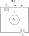
- FIG. 2 is a plan view showing the slide.
- the slide 41 is a member having a substantially rectangular shape when viewed in a plan view, and is suspended by the two slide driving units 42.
- the slide 41 is provided with a hole portion 41a into which the main body portion 32b of the piston 32 can be inserted, and a connection portion 41b to which a suspending part 42a (details will be described later) of the slide driving unit 42 is connected.
- the shape of the slide 41 when viewed in a plan view is not limited to the rectangular shape and may be appropriately set to another shape, based on the positional relationship with other parts, or the like.
- the hole portion 41a is a through-hole extending in the elevating direction at the center of the slide 41 and a peripheral edge (a part of the slide 41) configuring the through-hole, and the center thereof coincides with the central axis of the piston 32.
- a diameter Dc of the hole portion 41a when viewed in a plan view is equal to or larger than the diameter Db of the tip surface 32c of the main body portion 32b of the piston 32. In a case where the diameter Dc of the hole portion 41a is equal to the diameter Db of the tip surface, if any one of the piston 32 and the slide 41 moves up and down, the piston 32 and the slide 41 slide with respect to each other in the hole portion 41a.
- connection portion 41b of two connection portions 41b is provided in the vicinity of a corner portion of the slide 41.
- the other connection portion 41b is provided at a position which is point-symmetrical to the one connection portion 41b with respect to the center of the slide 41.
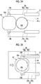
- FIGS. 3A and 3B are plan views showing a detailed structure of the die clamping force transmitting unit 51, in which FIG. 3A shows a state where the hole portion 41a is exposed and FIG. 3B shows a state where the hole portion 41a is covered with a block body 53.
- the die clamping force transmitting unit 51 is a member which is movable between the piston 32 and the slide 41 in the elevating direction and between a position (a first position) where the hole portion 41a is covered to prevent the piston 32 from entering the hole portion 41a and a position (a second position) where it retreats from the first position to allow the piston 32 to enter the hole portion 41a.
- the die clamping force transmitting unit 51 is a member which receives the die clamping force from the piston 32 when the die clamping force transmitting unit 51 is located at the first position, and transmits the die clamping force to the slide 41. As shown in FIGS.
- the die clamping force transmitting unit 51 includes the block body 53 (a force transmitting body) which is disposed on the slide 41 and has a size to cover the hole portion 41a, and two block body driving units 54 (force transmitting body driving units) which are disposed on the slide 41 and drive the block body 53 in the horizontal direction.
- the block body 53 is a member which can directly receive the die clamping force from the piston 32 when it is located at the first position, and includes a main body portion 53a and two ear portions 53b which are connected to the block body driving unit 54.
- the area of the main body portion 53a is larger than the area of the hole portion 41a of the slide 41.
- FIG. 3B in a case where the main body portion 53a moves to the first position and completely covers the hole portion 41a, at least a part of the main body portion 53a is in contact with the slide 41.
- the main body portion 32b of the piston 32 can be inserted into the hole portion 41a and the slide 41 can move up such that the upper surface thereof can be located further toward the base end portion 32a side than the tip surface 32c of the piston 32.
- the two block body driving units 54 are provided on the slide 41 with the center of the hole portion 41a interposed therebetween, and each has a connection part 54a which is connected to the block body 53, and a driving unit 54b which drives the connection part 54a to advance and retreat it in the horizontal direction.
- the connection part 54a is a rod-like member which is driven according to the operation of the driving unit 54b, and extends along one direction in the horizontal direction. Further, two connection part 54a extend so as to be parallel to each other.
- the driving unit 54b is, for example, a hydraulic cylinder, and similar to the hydraulic cylinder 31, hydraulic oil is supplied thereto, whereby the connection part 54a advances and retreats. For this reason, the block body 53 is subjected to translation control by the block body driving units 54.
- the number of the block body driving units 54 is not limited to two, and one or three or more block body driving units 54 may be provided.
- the driving unit 54b pushes out the connection part 54a to the outside, whereby the block body 53 moves away from the driving unit 54b. In this way, as shown in FIG. 3A , the block body 53 is retreated to the second position. Further, the driving unit 54b pulls back the connection part 54a to the inside thereof, whereby the block body 53 comes close to the driving unit 54b. In this way, as shown in FIG. 3B , the block body 53 is advanced to the first position.
- each of the two slide driving units 42 is a member which advances and retreats the slide 41 in the elevating direction.
- Each of the two slide driving units 42 includes the suspending part 42a for suspending the slide 41, and a driving unit 42b which drives the suspending part 42a to advance and retreat it in the elevating direction.
- the suspending part 42a is a rod-like member (a sub-piston) which is driven according to the operation of the driving unit 42b, and extends along the elevating direction. Further, a lower end of the suspending part 42a is connected to a corresponding connection portion 41b (refer to FIG. 2 ) of the slide 41.
- the slide driving unit 42 has a hydraulic piston cylinder, and an oil chamber in which the hydraulic oil which is supplied from the oil supply unit 33 is accommodated. For this reason, it can be said that the suspending part 42a moves up and down by the hydraulic oil which is supplied into the driving unit 42b and the slide driving unit 42 has the oil supply unit 33.
- a diameter Dd of the sub-piston that is the suspending part 42a is smaller than the diameter Da of the base end portion 32a of the piston 32. Further, the total value of the cross-sectional areas of the sub-pistons of the plurality of slide driving units 42 is smaller than the cross-sectional area of the base end portion 32a of the piston 32. For this reason, in a case where the hydraulic oil in the same condition (amount and pressure) is supplied from the oil supply unit 33 to each of the die clamping force generating unit and the slide driving unit 42, the hydraulic oil supplied to the slide driving unit 42 can drive the slide 41 at high speed. Further, the stroke (the maximum distance in which the slide 41 can advance and retreat) in the slide driving unit 42 is longer than the stroke in the die clamping force generating unit 22.
- the slide 41 and the die clamping force transmitting unit 51 are integrated with each other. For this reason, in a case where the slide 41 advances (moves down) in the elevating direction, the die clamping force transmitting unit 51 moves down by the same amount as the slide 41.
- the control unit 5 is a member for controlling the driving of the die clamping force generating unit 22 and the slide driving unit 42, and is, for example, a central processing unit (CPU) or the like.
- the control unit 5 controls the driving of the die clamping force generating unit 22, for example, by controlling the oil supply to the hydraulic cylinder 31 by the oil supply unit 33.
- the control unit 5 controls the driving of the slide driving unit 42, for example, by controlling the oil supply to the slide driving unit 42 by the oil supply unit 33.
- the control of the die clamping force generating unit 22 by the control unit 5 and the control of the slide driving unit 42 by the control unit 5 are independent. For this reason, the piston 32 and the slide 41 can advance in the elevating direction at different timings.
- control unit 5 controls the slide driving unit 42 such that the slide 41 advances (moves down) in the elevating direction, and then controls the die clamping force generating unit 22 such that the piston 32 advances (moves down) in the elevating direction.
- the control unit 5 may control the driving of the block body driving unit 54.
- FIGS. 4 and 5 are diagrams showing a forming process by the forming apparatus.
- the positions of the piston 32 and the slide 41 are set (a preparation process) .
- the piston 32 is moved up (retreated) and the suspending part 42a of the slide driving unit 42 is moved up (retreated).
- the slide 41 is moved up until the main body portion 32b of the piston 32 can be inserted (enter) into the hole portion 41a of the slide 41. In this way, the distance between the lower die M1 and the upper die M2 in the elevating direction is increased to facilitate loading of a workpiece between the lower die M1 and the upper die M2.
- the slide 41 moves up further to the base end portion 32a side than the tip surface 32c of the piston 32 without being obstructed by the block body 53.
- the tip surface 32c of the piston 32 is located within the lower end of the hole portion 41a of the slide 41.
- the slide 41 is moved down (advanced) such that the piston 32 is located outside the hole portion 41a of the slide 41 (a slide advancing process). Specifically, after the workpiece is placed on the lower die M1, the suspending part 42a of the slide driving unit 42 moves down to a predetermined position, thereby moving the slide 41 down. In this way, the distance between the lower die M1 and the upper die M2 in the elevating direction is reduced. At this time, since the sub-piston of the slide driving unit 42 has a smaller diameter than the piston 32, the slide 41 moves down at high speed.
- the slide 41 moving down to a predetermined position corresponds to the slide 41 moving down to a position where the distance between the tip surface 32c of the piston 32 and the slide 41 in the elevating direction is equal to or greater than the thickness of the block body 53.
- the block body driving unit 54 is controlled to advance the block body 53 to the first position (a block body advancing process).
- the block body 53 is disposed between the piston 32 and the slide 41 in the elevating direction.
- the block body 53 is in contact with the tip surface 32c of the piston 32 or has a slight gap at the first position.
- the piston 32 is moved down (advanced) (a piston advancing process).
- the pressure associated with the lowering of the piston 32 is transmitted to the block body 53.
- the pressure transmitted to the block body 53 is transmitted to the slide 41, and thus the slide 41 moves down.
- the distance between the lower die M1 and the upper die M2 is further reduced and the lower die M1 and the upper die M2 are brought into close contact with each other (die-closing).
- the upper die M2 is pressed through the piston 32, whereby the lower die M1 and the upper die M2 are subjected to strong die-clamping, and forming of the workpiece is performed.
- the piston 32 is moved up (retreated) .
- the slide 41 is moved up (retreated), whereby the piston 32, the slide 41, and the block body 53 are returned to the places shown in the first process. Finally, the workpiece is recovered from the forming apparatus 1.
- the piston 32 capable of advancing and retreating in the elevating direction can be inserted into a hole portion 41a provided in the slide 41.
- a hole or the like, into which a rod is inserted may not be provided in the piston 32. Therefore, it is possible to prevent the piston 32 from becoming large in excess of a cross-sectional area that generates the required die clamping force.
- the forming apparatus 1 is provided with the die clamping force transmitting unit 51 having the block body 53 which transmits the die clamping force from the piston 32 to the slide 41 when the block body 53 is located at the first position where it covers the hole portion 41a to prevent the piston 32 from entering the hole portion 41a.
- the block body 53 is located at the first position, whereby the die clamping force from the piston 32 can be favorably transmitted to the upper die M2 through the block body 53 and the slide 41.
- the hydraulic cylinder 31 to which the hydraulic oil is supplied in the die clamping force generating unit 22 can also be reduced in size. Therefore, compactification of the die clamping force generating unit 22 having the piston 32 and the hydraulic cylinder 31 can be realized.
- the slide 41 is retreated further toward the base end portion 32a side than the tip surface 32c of the piston 32.
- the slide 41 can be retreated without providing a hole or the like, into which a rod is inserted, in the piston 32, it is possible to prevent the piston 32 from becoming large in excess of the cross-sectional area which generates the required die clamping force.
- the piston 32 is moved down to perform die-clamping of the lower die M1 and the upper die M2 through the block body 53 and the slide 41. In this way, the die clamping force from the piston 32 can be favorably transmitted to the upper die M2.
- the block body 53 advances to the first position, whereby the amount of movement of the piston 32 can be reduced, the hydraulic cylinder 31 for driving the piston 32 can also be reduced in size. Therefore, compactification of the die clamping force generating unit 22 having the piston 32 and the hydraulic cylinder 31 can be realized.
- the piston 32 may be slidable with respect to the slide 41 in the hole portion 41a.
- the slide 41 and the piston 32 can be independently advanced and retreated.
- the forming apparatus 1 is provided with the control unit 5 that controls the driving of each of the die clamping force generating unit 22 and the slide driving unit 42, and the control unit 5 controls the slide driving unit 42 such that the slide 41 advances in the advancing and retreating direction, and then controls the die clamping force generating unit 22 such that the piston 32 advances in the advancing and retreating direction, and therefore, the control unit 5 can independently advance and retreat the slide 41 and the piston 32.
- the control unit 5 can control the driving of the piston 32 so as to apply a high die clamping force to the slide 41 while controlling the slide 41 to be driven at high speed by the slide driving unit 42. In this way, in one forming cycle in the forming apparatus 1, it is possible to achieve both reduction in cycle time and occurrence of a high die clamping force.
- the die clamping force transmitting unit 51 is controlled to advance and retreat in a translation direction orthogonal to the elevating direction, the advancing and retreating direction of the piston 32 and the slide 41 and the advancing and retreating direction of the block body 53 in the die clamping force transmitting unit 51 are orthogonal to each other. In this way, after the slide 41 moves down, the block body 53 can be easily advanced to the first position between the piston 32 and the slide 41.
- the slide driving unit 42 has one or a plurality of hydraulic piston cylinders in which the sub-pistons advance and retreat by supplying hydraulic oil thereto, and since the total value of the cross-sectional areas of the sub-pistons is smaller than the cross-sectional area of the piston 32, the sub-piston can be driven at higher speed than the piston 32, although the sub-piston cannot apply a larger pressure than the piston 32 to the slide 41. For this reason, the slide driving unit 42 can drive the slide 41 at high speed.
- the piston 32 is driven at lower speed than the sub-piston, the piston can apply a larger pressure than the sub-piston to the block body 53, the slide 41, and the like. Therefore, in one forming cycle in the forming apparatus 1, it is possible to achieve both reduction in cycle time due to high-speed driving of the slide 41 by the slide driving unit 42 and occurrence of a high die clamping force due to the driving of the piston 32.
- the present invention is not limited to the embodiment described above.
- the upper die M2 is not driven and the lower die M1 may be driven.
- the forming apparatus 1 is provided with a mechanism for driving the lower die M1 in place of the slide 41 and the slide driving unit 42.
- both the upper die M2 and the lower die M1 may be driven.
- the upper die M2 and the like do not need to be necessarily driven along the elevating direction.
- the direction in which the dies are put together is not limited to the elevating direction.
- the direction in which the block body 53 moves (a perpendicular direction orthogonal to the direction in which the piston 32 and the like advance and retreat) is not limited to the horizontal direction.
- the forming apparatus 1 includes, in addition to the lower die M1 and the upper die M2, a holding mechanism for holding a workpiece made of a hollow member between the lower die M1 and the upper die M2, a heating mechanism for heating the hollow member, a blow mechanism for blowing high pressure gas into the hollow member, a cooling mechanism for cooling the lower die M1 and the upper die M2, and the like.
- the piston 32 presses the upper die M2 (or the slide 41) through the block body 53 or the like from a state where the upper die M2 (or the slide 41) is completely moved down or immediately before the upper die M2 (or the slide 41) is completely moved down.
- the distance for the stroke of the piston 32 may be shorter than that in forging forming or the like, and a time required for the stroke of the piston 32 can be shortened. Therefore, according to the expansion forming using the forming apparatus 1, the die clamping force generating unit 22 having the piston 32 can be made more compact and the forming time can be shortened.
- At least one of the slide driving unit 42 and the block body driving unit 54 may be a driving mechanism other than the hydraulic piston cylinder.
- it may be an electric actuator or the like.
- the number of each of the slide driving unit 42 and the block body driving unit 54 is not limited to two.
Landscapes
- Engineering & Computer Science (AREA)
- Mechanical Engineering (AREA)
- Physics & Mathematics (AREA)
- Fluid Mechanics (AREA)
- Mounting, Exchange, And Manufacturing Of Dies (AREA)
- Moulds For Moulding Plastics Or The Like (AREA)
- Press Drives And Press Lines (AREA)
- Forging (AREA)
Abstract
Description
- Certain embodiments of the present invention relate to a forming apparatus and a forming method.
- As one of forming apparatuses using a die, there is a press machine which advances and retreats the die by using a hydraulic cylinder and a piston and presses a workpiece with the die.
PTL 1 below discloses a hydraulic press machine which includes a rod (a piston) which strokes in the interior of a main cylinder by using hydraulic pressure, a slide, driving of which is controlled by a slide elevating cylinder, an elongation rod which is placed on the slide and can be inserted into an insertion hole provided in the rod, and a shutter which opens and closes the insertion hole. In this hydraulic press machine, after the slide is moved down by the slide elevating cylinder to pull out the elongation rod from the insertion hole, the shutter is moved between the rod and the elongation rod so as to close the insertion hole. Thereafter, the rod is moved down, and the slide is moved down through the shutter and the elongation rod, whereby the stroke of the rod is shortened, and thus improvement in working efficiency is attained. - [PTL 1] Japanese Unexamined Patent Publication No.
2011-88167 - In a case where the insertion hole is provided in the rod, as in the hydraulic press machine described above, it is necessary to increase the size of the rod in order for the rod to withstand a large load acting on the rod at the time of forming of a workpiece. For this reason, the main cylinder and the like for driving the rod also tend to be increased in size. In the hydraulic press machine as described above, it is required to make the rod, the main cylinder, and the like compact while maintaining working efficiency.
- The present invention has an object to provide a forming apparatus and a forming method, in which it is possible to realize compactification of a die clamping force generating unit having a piston.
- According to an aspect of the present invention, there is provided a forming apparatus for forming a workpiece by performing die-closing of a pair of dies, includes: a slide on which one of the pair of dies is mounted and which can advance and retreat in an advancing and retreating direction which is a direction toward the other die; a die clamping force generating unit which has a piston movable in the advancing and retreating direction by supplying hydraulic oil thereto and generates a die clamping force; a slide driving unit which advances and retreats the slide in the advancing and retreating direction; and a die clamping force transmitting unit which transmits the die clamping force from the die clamping force generating unit to the slide, in which the slide has a hole portion into which the piston can be inserted, and the die clamping force transmitting unit includes a force transmitting body which is movable between a first position where the force transmitting body covers the hole portion to prevent the piston from entering the hole portion and a second position where the force transmitting body retreats from the first position to allow the piston to enter the hole portion, and transmits the die clamping force from the piston to the slide when the force transmitting body is located at the first position, and a force transmitting body driving unit which moves the force transmitting body.
- According to the forming apparatus, a piston capable of advancing and retreating in the advancing and retreating direction is made to be able to be inserted into the hole portion provided in the slide. In this way, when the slide is retreated further toward the base end side than the tip of the piston, it is not necessary to a hole or the like, into which a rod is inserted, in the piston, as in the related art. Therefore, it is possible to prevent the piston from becoming large in excess of a cross-sectional area which generates the required die clamping force. Further, the forming apparatus has the die clamping force transmitting unit having the force transmitting body for transmitting the die clamping force from the piston to the slide when the force transmitting body is located at the first position where the force transmitting body covers the hole portion to prevent the piston from entering the hole portion. In this way, when the die-clamping of the dies is performed, the force transmitting body is located at the first position, whereby the die clamping force from the piston can be favorably transmitted to the die through the force transmitting body and the slide. In addition, since the amount of movement of the piston can be reduced due to using the die clamping force transmitting unit, the portion to which the hydraulic oil is supplied in the die clamping force generating unit can also be reduced in size. That is, compactification of the die clamping force generating unit having the piston can be realized.
- Here, when the slide advances and retreats by the slide driving unit, the piston may be slidable with respect to the slide in the hole portion. In this case, the slide and the piston can be independently advanced and retreated.
- Further, the forming apparatus may further include a control unit which controls driving of each of the die clamping force generating unit and the slide driving unit, and the control unit may control the slide driving unit such that the slide advances in the advancing and retreating direction, and then control the die clamping force generating unit such that the piston advances in the advancing and retreating direction. Due to such a control of the control unit, the slide and the piston can be independently advanced and retreated. For this reason, the control unit can control the driving of the piston so as to apply a high die clamping force to the slide, while controlling the slide to be driven at high speed by the slide driving unit. In this way, in one forming cycle in the forming apparatus, it is possible to achieve both reduction in cycle time and occurrence of a high die clamping force.
- Further, the die clamping force transmitting unit may be controlled to advance and retreat in a perpendicular direction orthogonal to the advancing and retreating direction. In this case, the advancing and retreating directions of the piston and the slide and the advancing and retreating direction of the die clamping force transmitting unit are orthogonal to each other. In this way, for example, after the slide moves down, the die clamping force transmitting unit can be easily advanced to the first position between the piston and the slide.
- Further, the slide driving unit may include one or a plurality of hydraulic piston cylinders in which sub-pistons advance and retreat by supplying hydraulic oil thereto, and a total value of cross-sectional areas of the sub-pistons may be smaller than a cross-sectional area of the piston. In this case, although the sub-piston cannot apply larger pressure than the piston to the slide, the sub-piston can be driven at higher speed than the piston. For this reason, the slide driving unit can drive the slide at high speed. In addition, although the piston is driven at lower speed than the sub-piston, the piston can apply larger pressure than the sub-piston to the force transmitting body, the slide, and the like. Therefore, in one forming cycle in the forming apparatus, it is possible to achieve both reduction in cycle time due to the high-speed driving of the slide by the slide driving unit and occurrence of a high die clamping force due to the driving of the piston.
- Further, a workpiece disposed between the pair of dies may be expansion-formed by performing die-closing of the pair of dies. For example, in a case where the forming apparatus performs forging forming, forming resistance is generated due to contact between a die and a workpiece, and in order to overcome the forming resistance and put the dies together, it is necessary to press the die with a piston. For this reason, in a case where forging forming of a workpiece is performed with the forming apparatus, the piston also has to advance by a certain distance, and thus it is necessary to secure a distance for the stroke of the piston. In contrast, in a case where expansion forming of a workpiece is performed with the forming apparatus, it is favorable if the piston presses the die through the force transmitting body or the like from a state where the die on one side (or the slide) is completely moved down or immediately before the die on one side (or the slide) is completely moved down. In this case, the distance for the stroke of the piston may be shorter than that in forging forming or the like, and a time required for the stroke of the piston can be shortened. Therefore, according to the expansion forming using the forming apparatus, the die clamping force generating unit having the piston can be made more compact and the forming time can be shortened.
- Further, according to another aspect of the present invention, there is provided a forming method including: inserting a piston of a die clamping force generating unit into a hole portion provided in a slide; advancing the slide in a direction in which dies are put together such that the piston is located outside the hole portion of the slide; advancing a die clamping force transmitting unit to a position between the slide and the piston, which prevents the piston from entering the hole portion; advancing the piston in the direction in which the dies are put together; and performing die-clamping of the dies through the die clamping force transmitting unit and the slide.
- According to this forming method, since the piston of the die clamping force generating unit is inserted into the hole portion provided in the slide, when the slide is retreated further toward the base end side than the tip of the piston, it is not necessary to provide a hole or the like, into which a rod is inserted, in the piston, as in the related art. Therefore, it is possible to prevent the piston from becoming large in excess of a cross-sectional area which generates the required die clamping force. Further, after the die clamping force transmitting unit is advanced to a position where the piston is prevented from entering the hole portion, the piston is advanced in the direction in which the dies are put together, and die-clamping of the dies is performed through the die clamping force transmitting unit and the slide. In this way, the die clamping force from the piston can be favorably transmitted to the die through the die clamping force transmitting unit and the slide. In addition, since the amount of movement of the piston can be reduced due to the die clamping force transmitting unit, the die clamping force generating unit for driving the piston can also be reduced in size. Therefore, compactification of the die clamping force generating unit having the piston can be realized.
- In this manner, according to the present invention, it is possible to provide a forming apparatus and a forming method, in which it is possible to realize compactification of a die clamping force generating unit having a piston.
-
-
FIG. 1 is a schematic configuration diagram of a forming apparatus. -
FIG. 2 is a plan view showing a slide. -
FIGS. 3A and 3B are plan views showing a detailed structure of a die clamping force transmitting unit, in whichFIG. 3A shows a state where a hole portion is exposed andFIG. 3B shows a state where the hole portion is covered with a block body. -
FIG. 4 is a diagram showing a manufacturing process by the forming apparatus. -
FIG. 5 is a diagram showing the manufacturing process by the forming apparatus, which followsFIG. 4 . - Hereinafter, preferred embodiments of a forming apparatus and a forming method according to the present invention will be described with reference to the drawings. In the respective drawings, identical or corresponding parts are denoted by the same reference numerals, and overlapping description is omitted.
-
FIG. 1 is a schematic configuration diagram of a forming apparatus . As shown inFIG. 1 , a formingapparatus 1 for bringing a pair of dies close to each other to pressure-form a workpiece by the dies includes a lower frame 2 (a bed), an upper frame 3 (a crown), a plurality of columnar frames 4 (uprights) connecting thelower frame 2 and theupper frame 3, a die clamping force generating unit 22 (details will be described later), two slide driving units 42 (details will be described later), and acontrol unit 5 that controls driving of each of the die clampingforce generating unit 22 and theslide driving units 42. Each of thelower frame 2, theupper frame 3, and thecolumnar frame 4 is configured by combining members made of steel, for example. In the following, an extension direction of thecolumnar frame 4 is set to be an elevating direction, and a direction orthogonal to the elevating direction is set to be a horizontal direction. In this embodiment, the workpiece is formed by advancing and retreating at least one of the dies in the elevating direction. That is, in this embodiment, the elevating direction corresponds to a direction in which the dies are put together. - The
lower frame 2 is provided with a bed 12 (a bolster) to which a lower die M1 is mounted and fixed. The lower die M1 is configured of a steel block, and a forming surface (not shown) for forming a forming space is provided on the upper surface thereof. - The
upper frame 3 is provided with the die clampingforce generating unit 22 provided at the center thereof, and adie driving unit 23 which supports and drives an upper die M2. The upper die M2 is configured of a steel block similar to the lower die M1, and a forming surface (not shown) for forming a forming space is provided on the lower surface thereof. - The die clamping
force generating unit 22 is a mechanism which generates a die clamping force that prevents die-opening of the pair of dies when forming the workpiece, and includes ahydraulic cylinder 31, apiston 32 which is slidable in thehydraulic cylinder 31 and is capable of advancing and retreating in the elevating direction, anoil supply unit 33 which supplies hydraulic oil to an oil chamber in thehydraulic cylinder 31. - The
hydraulic cylinder 31 is a substantially tubular member extending in the elevating direction and has the oil chamber in which the hydraulic oil is accommodated. The interior of thehydraulic cylinder 31 is partitioned into alower region 31a (refer toFIG. 1 ) and anupper region 31b (refer toFIG. 5 ) by abase end portion 32a (details will be described later) of thepiston 32. Thelower region 31a and theupper region 31b configure the oil chamber. Thelower region 31a is connected to theoil supply unit 33 through anoil passage 34, and theupper region 31b is connected to theoil supply unit 33 through anoil passage 35. The amount of hydraulic oil which is filled in thelower region 31a and theupper region 31b is controlled by theoil supply unit 33. - The
piston 32 is a member which moves up and down by the hydraulic oil which is supplied into thehydraulic cylinder 31, and is provided with thebase end portion 32a which is located at one end (an upper end inFIG. 1 ) thereof and is in sliding contact with an inner wall of thehydraulic cylinder 31, and amain body portion 32b which is located below thebase end portion 32a. Themain body portion 32b has a substantially columnar shape extending toward thelower frame 2. A diameter Db of themain body portion 32b is smaller than a diameter Da of thebase end portion 32a. Aflat tip surface 32c is provided at the other end (a lower end inFIG. 1 ) of thepiston 32. The central axes of thehydraulic cylinder 31 and thepiston 32 coincide with each other. - The
oil supply unit 33 is a member for supplying the hydraulic oil to thelower region 31a and theupper region 31b of thehydraulic cylinder 31, and is configured of, for example, a tank in which the hydraulic oil is stored, a pump for discharging the hydraulic oil in the tank, and the like. Further, theoil supply unit 33 recovers the hydraulic oil filled in thelower region 31a and theupper region 31b. For example, in a case where theoil supply unit 33 supplies the hydraulic oil to thelower region 31a, theoil supply unit 33 recovers the hydraulic oil filled in theupper region 31b. In this way, theoil supply unit 33 adjusts the volume of the hydraulic oil filled in thelower region 31a and theupper region 31b and controls the position of thepiston 32 in the elevating direction. Valves (not shown) are provided in theoil passage 34 and theoil passage 35, and by controlling the valves, it is possible to change a supply destination to which the hydraulic oil is supplied from theoil supply unit 33. - The
die driving unit 23 is a mechanism for driving the upper die M2 to advance and retreat it in the elevating direction, and includes aslide 41 on which the upper die M2 is mounted, and a plurality of (in this embodiment, two)slide driving units 42 which support and drive theslide 41. The number of theslide driving units 42 is not limited and may be one. -
FIG. 2 is a plan view showing the slide. As shown inFIG. 2 , theslide 41 is a member having a substantially rectangular shape when viewed in a plan view, and is suspended by the twoslide driving units 42. Theslide 41 is provided with ahole portion 41a into which themain body portion 32b of thepiston 32 can be inserted, and aconnection portion 41b to which a suspendingpart 42a (details will be described later) of theslide driving unit 42 is connected. The shape of theslide 41 when viewed in a plan view is not limited to the rectangular shape and may be appropriately set to another shape, based on the positional relationship with other parts, or the like. - The
hole portion 41a is a through-hole extending in the elevating direction at the center of theslide 41 and a peripheral edge (a part of the slide 41) configuring the through-hole, and the center thereof coincides with the central axis of thepiston 32. A diameter Dc of thehole portion 41a when viewed in a plan view is equal to or larger than the diameter Db of thetip surface 32c of themain body portion 32b of thepiston 32. In a case where the diameter Dc of thehole portion 41a is equal to the diameter Db of the tip surface, if any one of thepiston 32 and theslide 41 moves up and down, thepiston 32 and theslide 41 slide with respect to each other in thehole portion 41a. That is, thepiston 32 and a part of theslide 41, which configures thehole portion 41a, can come into contact with each other. Further, oneconnection portion 41b of twoconnection portions 41b is provided in the vicinity of a corner portion of theslide 41. Theother connection portion 41b is provided at a position which is point-symmetrical to the oneconnection portion 41b with respect to the center of theslide 41. - Returning to
FIG. 1 , a die clampingforce transmitting unit 51 which transmits a die clamping force that is generated from the die clampingforce generating unit 22 to the upper die M2 is provided on theslide 41. Here, the die clampingforce transmitting unit 51 will be described in detail usingFIGS. 3A and 3B. FIGS. 3A and 3B are plan views showing a detailed structure of the die clampingforce transmitting unit 51, in whichFIG. 3A shows a state where thehole portion 41a is exposed andFIG. 3B shows a state where thehole portion 41a is covered with ablock body 53. - The die clamping
force transmitting unit 51 is a member which is movable between thepiston 32 and theslide 41 in the elevating direction and between a position (a first position) where thehole portion 41a is covered to prevent thepiston 32 from entering thehole portion 41a and a position (a second position) where it retreats from the first position to allow thepiston 32 to enter thehole portion 41a. The die clampingforce transmitting unit 51 is a member which receives the die clamping force from thepiston 32 when the die clampingforce transmitting unit 51 is located at the first position, and transmits the die clamping force to theslide 41. As shown inFIGS. 3A and 3B , the die clampingforce transmitting unit 51 includes the block body 53 (a force transmitting body) which is disposed on theslide 41 and has a size to cover thehole portion 41a, and two block body driving units 54 (force transmitting body driving units) which are disposed on theslide 41 and drive theblock body 53 in the horizontal direction. - The
block body 53 is a member which can directly receive the die clamping force from thepiston 32 when it is located at the first position, and includes amain body portion 53a and twoear portions 53b which are connected to the blockbody driving unit 54. When viewed in a plan view, the area of themain body portion 53a is larger than the area of thehole portion 41a of theslide 41. For this reason, as shown inFIG. 3B , in a case where themain body portion 53a moves to the first position and completely covers thehole portion 41a, at least a part of themain body portion 53a is in contact with theslide 41. As shown inFIG. 3A , in a case where themain body portion 53a moves to the second position, as shown inFIG. 1 , themain body portion 32b of thepiston 32 can be inserted into thehole portion 41a and theslide 41 can move up such that the upper surface thereof can be located further toward thebase end portion 32a side than thetip surface 32c of thepiston 32. - The two block
body driving units 54 are provided on theslide 41 with the center of thehole portion 41a interposed therebetween, and each has aconnection part 54a which is connected to theblock body 53, and adriving unit 54b which drives theconnection part 54a to advance and retreat it in the horizontal direction. Theconnection part 54a is a rod-like member which is driven according to the operation of thedriving unit 54b, and extends along one direction in the horizontal direction. Further, twoconnection part 54a extend so as to be parallel to each other. The drivingunit 54b is, for example, a hydraulic cylinder, and similar to thehydraulic cylinder 31, hydraulic oil is supplied thereto, whereby theconnection part 54a advances and retreats. For this reason, theblock body 53 is subjected to translation control by the blockbody driving units 54. The number of the blockbody driving units 54 is not limited to two, and one or three or more blockbody driving units 54 may be provided. - The driving
unit 54b pushes out theconnection part 54a to the outside, whereby theblock body 53 moves away from the drivingunit 54b. In this way, as shown inFIG. 3A , theblock body 53 is retreated to the second position. Further, the drivingunit 54b pulls back theconnection part 54a to the inside thereof, whereby theblock body 53 comes close to thedriving unit 54b. In this way, as shown inFIG. 3B , theblock body 53 is advanced to the first position. - Returning to
FIG. 1 , each of the twoslide driving units 42 is a member which advances and retreats theslide 41 in the elevating direction. Each of the twoslide driving units 42 includes the suspendingpart 42a for suspending theslide 41, and adriving unit 42b which drives the suspendingpart 42a to advance and retreat it in the elevating direction. The suspendingpart 42a is a rod-like member (a sub-piston) which is driven according to the operation of thedriving unit 42b, and extends along the elevating direction. Further, a lower end of the suspendingpart 42a is connected to acorresponding connection portion 41b (refer toFIG. 2 ) of theslide 41. Theslide driving unit 42 has a hydraulic piston cylinder, and an oil chamber in which the hydraulic oil which is supplied from theoil supply unit 33 is accommodated. For this reason, it can be said that the suspendingpart 42a moves up and down by the hydraulic oil which is supplied into the drivingunit 42b and theslide driving unit 42 has theoil supply unit 33. - A diameter Dd of the sub-piston that is the suspending
part 42a is smaller than the diameter Da of thebase end portion 32a of thepiston 32. Further, the total value of the cross-sectional areas of the sub-pistons of the plurality ofslide driving units 42 is smaller than the cross-sectional area of thebase end portion 32a of thepiston 32. For this reason, in a case where the hydraulic oil in the same condition (amount and pressure) is supplied from theoil supply unit 33 to each of the die clamping force generating unit and theslide driving unit 42, the hydraulic oil supplied to theslide driving unit 42 can drive theslide 41 at high speed. Further, the stroke (the maximum distance in which theslide 41 can advance and retreat) in theslide driving unit 42 is longer than the stroke in the die clampingforce generating unit 22. - In this embodiment, the
slide 41 and the die clampingforce transmitting unit 51 are integrated with each other. For this reason, in a case where theslide 41 advances (moves down) in the elevating direction, the die clampingforce transmitting unit 51 moves down by the same amount as theslide 41. - The
control unit 5 is a member for controlling the driving of the die clampingforce generating unit 22 and theslide driving unit 42, and is, for example, a central processing unit (CPU) or the like. Thecontrol unit 5 controls the driving of the die clampingforce generating unit 22, for example, by controlling the oil supply to thehydraulic cylinder 31 by theoil supply unit 33. Further, thecontrol unit 5 controls the driving of theslide driving unit 42, for example, by controlling the oil supply to theslide driving unit 42 by theoil supply unit 33. The control of the die clampingforce generating unit 22 by thecontrol unit 5 and the control of theslide driving unit 42 by thecontrol unit 5 are independent. For this reason, thepiston 32 and theslide 41 can advance in the elevating direction at different timings. That is, due to supplying the hydraulic oil to theslide driving unit 42 and not supplying the hydraulic oil to the die clampingforce generating unit 22, thepiston 32 can be kept stopped even while theslide 41 moves down. In this embodiment, thecontrol unit 5 controls theslide driving unit 42 such that theslide 41 advances (moves down) in the elevating direction, and then controls the die clampingforce generating unit 22 such that thepiston 32 advances (moves down) in the elevating direction. Thecontrol unit 5 may control the driving of the blockbody driving unit 54. - Next, an example of a forming method using the forming
apparatus 1 according to this embodiment will be described usingFIGS. 4 and5 .FIGS. 4 and5 are diagrams showing a forming process by the forming apparatus. - First, as a first process, as shown in
FIG. 1 , the positions of thepiston 32 and theslide 41 are set (a preparation process) . In the first process, thepiston 32 is moved up (retreated) and the suspendingpart 42a of theslide driving unit 42 is moved up (retreated). At this time, theslide 41 is moved up until themain body portion 32b of thepiston 32 can be inserted (enter) into thehole portion 41a of theslide 41. In this way, the distance between the lower die M1 and the upper die M2 in the elevating direction is increased to facilitate loading of a workpiece between the lower die M1 and the upper die M2. In the first process, since theblock body 53 of the die clampingforce transmitting unit 51 is disposed at the second position on theslide 41, theslide 41 moves up further to thebase end portion 32a side than thetip surface 32c of thepiston 32 without being obstructed by theblock body 53. In this state, thetip surface 32c of thepiston 32 is located within the lower end of thehole portion 41a of theslide 41. - Next, as a second process, as shown in
FIG. 4 , theslide 41 is moved down (advanced) such that thepiston 32 is located outside thehole portion 41a of the slide 41 (a slide advancing process). Specifically, after the workpiece is placed on the lower die M1, the suspendingpart 42a of theslide driving unit 42 moves down to a predetermined position, thereby moving theslide 41 down. In this way, the distance between the lower die M1 and the upper die M2 in the elevating direction is reduced. At this time, since the sub-piston of theslide driving unit 42 has a smaller diameter than thepiston 32, theslide 41 moves down at high speed. Theslide 41 moving down to a predetermined position corresponds to theslide 41 moving down to a position where the distance between thetip surface 32c of thepiston 32 and theslide 41 in the elevating direction is equal to or greater than the thickness of theblock body 53. - Further, in the second process, after the
slide 41 is moved down, the blockbody driving unit 54 is controlled to advance theblock body 53 to the first position (a block body advancing process). In this way, theblock body 53 is disposed between thepiston 32 and theslide 41 in the elevating direction. In this embodiment, theblock body 53 is in contact with thetip surface 32c of thepiston 32 or has a slight gap at the first position. - Next, as a third process, as shown in
FIG. 5 , thepiston 32 is moved down (advanced) (a piston advancing process). In the third process, the pressure associated with the lowering of thepiston 32 is transmitted to theblock body 53. At this time, the pressure transmitted to theblock body 53 is transmitted to theslide 41, and thus theslide 41 moves down. In this way, the distance between the lower die M1 and the upper die M2 is further reduced and the lower die M1 and the upper die M2 are brought into close contact with each other (die-closing). In this state, the upper die M2 is pressed through thepiston 32, whereby the lower die M1 and the upper die M2 are subjected to strong die-clamping, and forming of the workpiece is performed. At this time, since thepiston 32 has a larger diameter than the sub-piston of theslide driving unit 42, although it is not possible to move theslide 41 down at high speed, it is possible to apply a large force to theslide 41 and the upper die M2 at the time of die-clamping. - After the third process, the
piston 32 is moved up (retreated) . Subsequently, after theblock body 53 is retreated to the second position, theslide 41 is moved up (retreated), whereby thepiston 32, theslide 41, and theblock body 53 are returned to the places shown in the first process. Finally, the workpiece is recovered from the formingapparatus 1. - As described above, according to the forming
apparatus 1 of this embodiment, thepiston 32 capable of advancing and retreating in the elevating direction can be inserted into ahole portion 41a provided in theslide 41. In this way, when theslide 41 is retreated further toward thebase end portion 32a side than thetip surface 32c of thepiston 32, a hole or the like, into which a rod is inserted, may not be provided in thepiston 32. Therefore, it is possible to prevent thepiston 32 from becoming large in excess of a cross-sectional area that generates the required die clamping force. Further, the formingapparatus 1 is provided with the die clampingforce transmitting unit 51 having theblock body 53 which transmits the die clamping force from thepiston 32 to theslide 41 when theblock body 53 is located at the first position where it covers thehole portion 41a to prevent thepiston 32 from entering thehole portion 41a. In this way, when the die-clamping of the lower die M1 and the upper die M2 is performed, theblock body 53 is located at the first position, whereby the die clamping force from thepiston 32 can be favorably transmitted to the upper die M2 through theblock body 53 and theslide 41. In addition, since the amount of movement of thepiston 32 can be reduced by using the die clampingforce transmitting unit 51, thehydraulic cylinder 31 to which the hydraulic oil is supplied in the die clampingforce generating unit 22 can also be reduced in size. Therefore, compactification of the die clampingforce generating unit 22 having thepiston 32 and thehydraulic cylinder 31 can be realized. - Further, according to the forming method using the forming
apparatus 1 of this embodiment, in the first process, theslide 41 is retreated further toward thebase end portion 32a side than thetip surface 32c of thepiston 32. At this time, since theslide 41 can be retreated without providing a hole or the like, into which a rod is inserted, in thepiston 32, it is possible to prevent thepiston 32 from becoming large in excess of the cross-sectional area which generates the required die clamping force. Further, in the third process, after theblock body 53 of the die clampingforce transmitting unit 51 is advanced to the first position where thepiston 32 is prevented from entering thehole portion 41a in the second process, thepiston 32 is moved down to perform die-clamping of the lower die M1 and the upper die M2 through theblock body 53 and theslide 41. In this way, the die clamping force from thepiston 32 can be favorably transmitted to the upper die M2. In addition, since theblock body 53 advances to the first position, whereby the amount of movement of thepiston 32 can be reduced, thehydraulic cylinder 31 for driving thepiston 32 can also be reduced in size. Therefore, compactification of the die clampingforce generating unit 22 having thepiston 32 and thehydraulic cylinder 31 can be realized. - Further, when the
slide 41 moves up and down (advances and retreats) by theslide driving unit 42, thepiston 32 may be slidable with respect to theslide 41 in thehole portion 41a. In this case, theslide 41 and thepiston 32 can be independently advanced and retreated. - Further, the forming
apparatus 1 is provided with thecontrol unit 5 that controls the driving of each of the die clampingforce generating unit 22 and theslide driving unit 42, and thecontrol unit 5 controls theslide driving unit 42 such that theslide 41 advances in the advancing and retreating direction, and then controls the die clampingforce generating unit 22 such that thepiston 32 advances in the advancing and retreating direction, and therefore, thecontrol unit 5 can independently advance and retreat theslide 41 and thepiston 32. For this reason, thecontrol unit 5 can control the driving of thepiston 32 so as to apply a high die clamping force to theslide 41 while controlling theslide 41 to be driven at high speed by theslide driving unit 42. In this way, in one forming cycle in the formingapparatus 1, it is possible to achieve both reduction in cycle time and occurrence of a high die clamping force. - Further, since the die clamping
force transmitting unit 51 is controlled to advance and retreat in a translation direction orthogonal to the elevating direction, the advancing and retreating direction of thepiston 32 and theslide 41 and the advancing and retreating direction of theblock body 53 in the die clampingforce transmitting unit 51 are orthogonal to each other. In this way, after theslide 41 moves down, theblock body 53 can be easily advanced to the first position between thepiston 32 and theslide 41. - Further, the
slide driving unit 42 has one or a plurality of hydraulic piston cylinders in which the sub-pistons advance and retreat by supplying hydraulic oil thereto, and since the total value of the cross-sectional areas of the sub-pistons is smaller than the cross-sectional area of thepiston 32, the sub-piston can be driven at higher speed than thepiston 32, although the sub-piston cannot apply a larger pressure than thepiston 32 to theslide 41. For this reason, theslide driving unit 42 can drive theslide 41 at high speed. In addition, although thepiston 32 is driven at lower speed than the sub-piston, the piston can apply a larger pressure than the sub-piston to theblock body 53, theslide 41, and the like. Therefore, in one forming cycle in the formingapparatus 1, it is possible to achieve both reduction in cycle time due to high-speed driving of theslide 41 by theslide driving unit 42 and occurrence of a high die clamping force due to the driving of thepiston 32. - In addition, by reducing the flow rate per unit time of the hydraulic oil which is supplied to the
hydraulic cylinder 31, for example, a prefill valve or the like for supplying and recovering a large amount of hydraulic oil becomes unnecessary. In this way, the number of members configuring the formingapparatus 1 can be reduced. - The preferred embodiment of the present invention has been described above. However, the present invention is not limited to the embodiment described above. For example, in the forming
apparatus 1 in the above embodiment, the upper die M2 is not driven and the lower die M1 may be driven. In this case, the formingapparatus 1 is provided with a mechanism for driving the lower die M1 in place of theslide 41 and theslide driving unit 42. Further, both the upper die M2 and the lower die M1 may be driven. Further, the upper die M2 and the like do not need to be necessarily driven along the elevating direction. In other words, the direction in which the dies are put together is not limited to the elevating direction. In this case, the direction in which theblock body 53 moves (a perpendicular direction orthogonal to the direction in which thepiston 32 and the like advance and retreat) is not limited to the horizontal direction. - Further, as the forming
apparatus 1 in the above embodiment and the forming method using the formingapparatus 1, forming other than forging forming, for example, expansion forming described in Japanese Unexamined Patent Publication No.2015-112608 apparatus 1 includes, in addition to the lower die M1 and the upper die M2, a holding mechanism for holding a workpiece made of a hollow member between the lower die M1 and the upper die M2, a heating mechanism for heating the hollow member, a blow mechanism for blowing high pressure gas into the hollow member, a cooling mechanism for cooling the lower die M1 and the upper die M2, and the like. - In a case of performing the expansion forming by using the forming
apparatus 1, for example, die-closing of the lower die M1 and the upper die M2 which are paired is performed and the workpiece disposed between the lower die M1 and the upper die M2 is expansion-formed. In the case of forging forming, forming resistance is generated due to contact between a die and a workpiece, and in order to overcome the forming resistance and further move the upper die M2 down, it is necessary to apply pressure with thepiston 32. For this reason, in a case where forging forming of a workpiece is performed with the formingapparatus 1, thepiston 32 also has to be moved down by a certain distance, and thus it is necessary to secure a distance for the stroke of thepiston 32. In contrast, in a case where expansion forming of a workpiece is performed with the formingapparatus 1, it is favorable if thepiston 32 presses the upper die M2 (or the slide 41) through theblock body 53 or the like from a state where the upper die M2 (or the slide 41) is completely moved down or immediately before the upper die M2 (or the slide 41) is completely moved down. In this case, the distance for the stroke of thepiston 32 may be shorter than that in forging forming or the like, and a time required for the stroke of thepiston 32 can be shortened. Therefore, according to the expansion forming using the formingapparatus 1, the die clampingforce generating unit 22 having thepiston 32 can be made more compact and the forming time can be shortened. - Further, in the embodiment described above, at least one of the
slide driving unit 42 and the blockbody driving unit 54 may be a driving mechanism other than the hydraulic piston cylinder. For example, it may be an electric actuator or the like. Further, the number of each of theslide driving unit 42 and the blockbody driving unit 54 is not limited to two. -
- 1: forming apparatus
- 2: lower frame
- 3: upper frame
- 4: columnar frame
- 5: control unit
- 22: die clamping force generating unit
- 23: die driving unit
- 31: hydraulic cylinder
- 32: piston
- 33: oil supply unit
- 41: slide
- 41a: hole portion
- 42: slide driving unit
- 42a: suspending part (sub-piston)
- 51: die clamping force transmitting unit
- 53: block body (force transmitting body)
- 54: block body driving unit (force transmitting body driving unit)
Claims (7)
- A forming apparatus for forming a workpiece by performing die-closing of a pair of dies, the forming apparatus comprising:a slide on which one of the pair of dies is mounted and which can advance and retreat in an advancing and retreating direction which is a direction toward the other die;a die clamping force generating unit which has a piston movable in the advancing and retreating direction by supplying hydraulic oil thereto and generates a die clamping force;a slide driving unit which advances and retreats the slide in the advancing and retreating direction; anda die clamping force transmitting unit which transmits the die clamping force from the die clamping force generating unit to the slide,wherein the slide has a hole portion into which the piston can be inserted, andthe die clamping force transmitting unit includesa force transmitting body which is movable between a first position where the force transmitting body covers the hole portion to prevent the piston from entering the hole portion and a second position where the force transmitting body retreats from the first position to allow the piston to enter the hole portion, and transmits the die clamping force from the piston to the slide when the force transmitting body is located at the first position, anda force transmitting body driving unit which moves the force transmitting body.
- The forming apparatus according to claim 1, wherein when the slide advances and retreats by the slide driving unit, the piston is slidable with respect to the slide in the hole portion.
- The forming apparatus according to claim 1 or 2, further comprising:a control unit which controls driving of each of the die clamping force generating unit and the slide driving unit,wherein the control unit controls the slide driving unit such that the slide advances in the advancing and retreating direction, and then controls the die clamping force generating unit such that the piston advances in the advancing and retreating direction.
- The forming apparatus according to any one of claims 1 to 3, wherein the die clamping force transmitting unit is controlled to advance and retreat in a perpendicular direction orthogonal to the advancing and retreating direction.
- The forming apparatus according to any one of claims 1 to 4, wherein the slide driving unit includes one or a plurality of hydraulic piston cylinders in which sub-pistons advance and retreat by supplying hydraulic oil thereto, and
a total value of cross-sectional areas of the sub-pistons is smaller than a cross-sectional area of the piston. - The forming apparatus according to any one of claims 1 to 5, wherein the workpiece disposed between the pair of dies is expansion-formed by performing die-closing of the pair of dies.
- A forming method comprising:inserting a piston of a die clamping force generating unit into a hole portion provided in a slide;advancing the slide in a direction in which dies are put together such that the piston is located outside the hole portion of the slide;advancing a die clamping force transmitting unit to a position between the slide and the piston, which prevents the piston from entering the hole portion;advancing the piston in the direction in which the dies are put together; andperforming die-clamping of the dies through the die clamping force transmitting unit and the slide.
Applications Claiming Priority (2)
| Application Number | Priority Date | Filing Date | Title |
|---|---|---|---|
| JP2016134237 | 2016-07-06 | ||
| PCT/JP2017/024701 WO2018008696A1 (en) | 2016-07-06 | 2017-07-05 | Molding device and molding method |
Publications (2)
| Publication Number | Publication Date |
|---|---|
| EP3482924A1 true EP3482924A1 (en) | 2019-05-15 |
| EP3482924A4 EP3482924A4 (en) | 2019-09-25 |
Family
ID=60912863
Family Applications (1)
| Application Number | Title | Priority Date | Filing Date |
|---|---|---|---|
| EP17824299.6A Withdrawn EP3482924A4 (en) | 2016-07-06 | 2017-07-05 | MOLDING DEVICE AND MOLDING METHOD |
Country Status (7)
| Country | Link |
|---|---|
| US (1) | US20190118500A1 (en) |
| EP (1) | EP3482924A4 (en) |
| JP (1) | JP6490873B2 (en) |
| KR (1) | KR20190024886A (en) |
| CN (1) | CN109414892A (en) |
| CA (1) | CA3027335A1 (en) |
| WO (1) | WO2018008696A1 (en) |
Family Cites Families (7)
| Publication number | Priority date | Publication date | Assignee | Title |
|---|---|---|---|---|
| JPH06617A (en) * | 1992-06-23 | 1994-01-11 | Toyota Motor Corp | Mold clamping device |
| JP3376507B2 (en) * | 1995-05-18 | 2003-02-10 | 株式会社名機製作所 | Mold clamping device of injection molding machine |
| CN100480034C (en) * | 2007-07-25 | 2009-04-22 | 天津市天锻压力机有限公司 | Stripper in use for large sized hydraulic machine |
| CN101670672B (en) * | 2009-08-14 | 2012-03-21 | 天津市天锻压力机有限公司 | Combined framewrok non pull rod type glass product hydraulic press with adjustable stroke |
| JP5443121B2 (en) * | 2009-10-21 | 2014-03-19 | 住友重機械工業株式会社 | Hydraulic press |
| JP6326224B2 (en) * | 2013-12-09 | 2018-05-16 | 住友重機械工業株式会社 | Molding equipment |
| CN204640890U (en) * | 2015-05-12 | 2015-09-16 | 天津太平洋超高压设备有限公司 | Shorten the Long Distances pressing hydraulic machine of compacting impulse stroke |
-
2017
- 2017-07-05 WO PCT/JP2017/024701 patent/WO2018008696A1/en not_active Ceased
- 2017-07-05 EP EP17824299.6A patent/EP3482924A4/en not_active Withdrawn
- 2017-07-05 KR KR1020187035247A patent/KR20190024886A/en not_active Ceased
- 2017-07-05 CA CA3027335A patent/CA3027335A1/en not_active Abandoned
- 2017-07-05 JP JP2018526421A patent/JP6490873B2/en active Active
- 2017-07-05 CN CN201780036634.4A patent/CN109414892A/en active Pending
-
2018
- 2018-12-21 US US16/230,052 patent/US20190118500A1/en not_active Abandoned
Also Published As
| Publication number | Publication date |
|---|---|
| EP3482924A4 (en) | 2019-09-25 |
| JPWO2018008696A1 (en) | 2019-02-14 |
| CN109414892A (en) | 2019-03-01 |
| JP6490873B2 (en) | 2019-03-27 |
| WO2018008696A1 (en) | 2018-01-11 |
| CA3027335A1 (en) | 2018-01-11 |
| KR20190024886A (en) | 2019-03-08 |
| US20190118500A1 (en) | 2019-04-25 |
Similar Documents
| Publication | Publication Date | Title |
|---|---|---|
| WO2005000497A1 (en) | Hydroforming apparatus with stacked dies | |
| JP5047053B2 (en) | Equipment for hydroforming metal elements | |
| JP5802252B2 (en) | Gear manufacturing method and forging apparatus therefor | |
| CN106807842A (en) | The slip buffer unit of forcing press | |
| US10479040B2 (en) | Device and method for controlling the primary drive of a fine blanking press | |
| CN104772422A (en) | Forging apparatus | |
| KR102322828B1 (en) | Shearing device for extrusion press | |
| JP2017030036A (en) | Vertical type casting apparatus, and method for moving holding furnace of vertical type casting apparatus | |
| US20190118500A1 (en) | Forming apparatus and forming method | |
| JP2001198644A (en) | Tool cassette having elastic die | |
| KR20190048727A (en) | Control device for forging press | |
| JP5979491B2 (en) | Double acting extrusion press | |
| JP6562075B2 (en) | Hybrid extrusion press | |
| EP4403278A1 (en) | Molding device | |
| CN119927113A (en) | A hydraulic press | |
| JP6821476B2 (en) | Blockage forging device | |
| JP2004276077A (en) | Hydroforming apparatus and method | |
| JP3213661U (en) | Processing equipment | |
| JP2000334537A (en) | Closed forging method and closed forging device | |
| JP6350790B2 (en) | Direct double acting extrusion press | |
| KR20090042314A (en) | Stem slide device | |
| CN209943226U (en) | Hydraulic horizontal forging machine | |
| CN104220181B (en) | extrusion device | |
| JP4956383B2 (en) | Press pressure correction device and correction method for transfer press | |
| WO2012039399A1 (en) | Press-forming method and press-forming device |
Legal Events
| Date | Code | Title | Description |
|---|---|---|---|
| STAA | Information on the status of an ep patent application or granted ep patent |
Free format text: STATUS: THE INTERNATIONAL PUBLICATION HAS BEEN MADE |
|
| PUAI | Public reference made under article 153(3) epc to a published international application that has entered the european phase |
Free format text: ORIGINAL CODE: 0009012 |
|
| STAA | Information on the status of an ep patent application or granted ep patent |
Free format text: STATUS: REQUEST FOR EXAMINATION WAS MADE |
|
| 17P | Request for examination filed |
Effective date: 20181207 |
|
| AK | Designated contracting states |
Kind code of ref document: A1 Designated state(s): AL AT BE BG CH CY CZ DE DK EE ES FI FR GB GR HR HU IE IS IT LI LT LU LV MC MK MT NL NO PL PT RO RS SE SI SK SM TR |
|
| AX | Request for extension of the european patent |
Extension state: BA ME |
|
| STAA | Information on the status of an ep patent application or granted ep patent |
Free format text: STATUS: EXAMINATION IS IN PROGRESS |
|
| A4 | Supplementary search report drawn up and despatched |
Effective date: 20190823 |
|
| RIC1 | Information provided on ipc code assigned before grant |
Ipc: B30B 15/22 20060101ALI20190819BHEP Ipc: B30B 1/34 20060101AFI20190819BHEP Ipc: B30B 1/32 20060101ALI20190819BHEP |
|
| 17Q | First examination report despatched |
Effective date: 20190910 |
|
| DAV | Request for validation of the european patent (deleted) | ||
| DAX | Request for extension of the european patent (deleted) | ||
| STAA | Information on the status of an ep patent application or granted ep patent |
Free format text: STATUS: THE APPLICATION IS DEEMED TO BE WITHDRAWN |
|
| 18D | Application deemed to be withdrawn |
Effective date: 20210716 |