EP3482909B1 - Laserverfestigungsvorrichtung zur herstellung von gegenständen durch schichtweises härten von material - Google Patents
Laserverfestigungsvorrichtung zur herstellung von gegenständen durch schichtweises härten von material Download PDFInfo
- Publication number
- EP3482909B1 EP3482909B1 EP18204791.0A EP18204791A EP3482909B1 EP 3482909 B1 EP3482909 B1 EP 3482909B1 EP 18204791 A EP18204791 A EP 18204791A EP 3482909 B1 EP3482909 B1 EP 3482909B1
- Authority
- EP
- European Patent Office
- Prior art keywords
- detector module
- optical module
- module
- laser
- detector
- Prior art date
- Legal status (The legal status is an assumption and is not a legal conclusion. Google has not performed a legal analysis and makes no representation as to the accuracy of the status listed.)
- Active
Links
Images


Classifications
-
- B—PERFORMING OPERATIONS; TRANSPORTING
- B29—WORKING OF PLASTICS; WORKING OF SUBSTANCES IN A PLASTIC STATE IN GENERAL
- B29C—SHAPING OR JOINING OF PLASTICS; SHAPING OF MATERIAL IN A PLASTIC STATE, NOT OTHERWISE PROVIDED FOR; AFTER-TREATMENT OF THE SHAPED PRODUCTS, e.g. REPAIRING
- B29C64/00—Additive manufacturing, i.e. manufacturing of three-dimensional [3D] objects by additive deposition, additive agglomeration or additive layering, e.g. by 3D printing, stereolithography or selective laser sintering
- B29C64/10—Processes of additive manufacturing
- B29C64/106—Processes of additive manufacturing using only liquids or viscous materials, e.g. depositing a continuous bead of viscous material
- B29C64/124—Processes of additive manufacturing using only liquids or viscous materials, e.g. depositing a continuous bead of viscous material using layers of liquid which are selectively solidified
- B29C64/129—Processes of additive manufacturing using only liquids or viscous materials, e.g. depositing a continuous bead of viscous material using layers of liquid which are selectively solidified characterised by the energy source therefor, e.g. by global irradiation combined with a mask
-
- B—PERFORMING OPERATIONS; TRANSPORTING
- B22—CASTING; POWDER METALLURGY
- B22F—WORKING METALLIC POWDER; MANUFACTURE OF ARTICLES FROM METALLIC POWDER; MAKING METALLIC POWDER; APPARATUS OR DEVICES SPECIALLY ADAPTED FOR METALLIC POWDER
- B22F10/00—Additive manufacturing of workpieces or articles from metallic powder
- B22F10/20—Direct sintering or melting
- B22F10/28—Powder bed fusion, e.g. selective laser melting [SLM] or electron beam melting [EBM]
-
- B—PERFORMING OPERATIONS; TRANSPORTING
- B22—CASTING; POWDER METALLURGY
- B22F—WORKING METALLIC POWDER; MANUFACTURE OF ARTICLES FROM METALLIC POWDER; MAKING METALLIC POWDER; APPARATUS OR DEVICES SPECIALLY ADAPTED FOR METALLIC POWDER
- B22F12/00—Apparatus or devices specially adapted for additive manufacturing; Auxiliary means for additive manufacturing; Combinations of additive manufacturing apparatus or devices with other processing apparatus or devices
- B22F12/40—Radiation means
- B22F12/44—Radiation means characterised by the configuration of the radiation means
-
- B—PERFORMING OPERATIONS; TRANSPORTING
- B22—CASTING; POWDER METALLURGY
- B22F—WORKING METALLIC POWDER; MANUFACTURE OF ARTICLES FROM METALLIC POWDER; MAKING METALLIC POWDER; APPARATUS OR DEVICES SPECIALLY ADAPTED FOR METALLIC POWDER
- B22F12/00—Apparatus or devices specially adapted for additive manufacturing; Auxiliary means for additive manufacturing; Combinations of additive manufacturing apparatus or devices with other processing apparatus or devices
- B22F12/90—Means for process control, e.g. cameras or sensors
-
- B—PERFORMING OPERATIONS; TRANSPORTING
- B29—WORKING OF PLASTICS; WORKING OF SUBSTANCES IN A PLASTIC STATE IN GENERAL
- B29C—SHAPING OR JOINING OF PLASTICS; SHAPING OF MATERIAL IN A PLASTIC STATE, NOT OTHERWISE PROVIDED FOR; AFTER-TREATMENT OF THE SHAPED PRODUCTS, e.g. REPAIRING
- B29C64/00—Additive manufacturing, i.e. manufacturing of three-dimensional [3D] objects by additive deposition, additive agglomeration or additive layering, e.g. by 3D printing, stereolithography or selective laser sintering
- B29C64/10—Processes of additive manufacturing
- B29C64/106—Processes of additive manufacturing using only liquids or viscous materials, e.g. depositing a continuous bead of viscous material
- B29C64/124—Processes of additive manufacturing using only liquids or viscous materials, e.g. depositing a continuous bead of viscous material using layers of liquid which are selectively solidified
-
- B—PERFORMING OPERATIONS; TRANSPORTING
- B29—WORKING OF PLASTICS; WORKING OF SUBSTANCES IN A PLASTIC STATE IN GENERAL
- B29C—SHAPING OR JOINING OF PLASTICS; SHAPING OF MATERIAL IN A PLASTIC STATE, NOT OTHERWISE PROVIDED FOR; AFTER-TREATMENT OF THE SHAPED PRODUCTS, e.g. REPAIRING
- B29C64/00—Additive manufacturing, i.e. manufacturing of three-dimensional [3D] objects by additive deposition, additive agglomeration or additive layering, e.g. by 3D printing, stereolithography or selective laser sintering
- B29C64/10—Processes of additive manufacturing
- B29C64/141—Processes of additive manufacturing using only solid materials
- B29C64/153—Processes of additive manufacturing using only solid materials using layers of powder being selectively joined, e.g. by selective laser sintering or melting
-
- B—PERFORMING OPERATIONS; TRANSPORTING
- B29—WORKING OF PLASTICS; WORKING OF SUBSTANCES IN A PLASTIC STATE IN GENERAL
- B29C—SHAPING OR JOINING OF PLASTICS; SHAPING OF MATERIAL IN A PLASTIC STATE, NOT OTHERWISE PROVIDED FOR; AFTER-TREATMENT OF THE SHAPED PRODUCTS, e.g. REPAIRING
- B29C64/00—Additive manufacturing, i.e. manufacturing of three-dimensional [3D] objects by additive deposition, additive agglomeration or additive layering, e.g. by 3D printing, stereolithography or selective laser sintering
- B29C64/20—Apparatus for additive manufacturing; Details thereof or accessories therefor
- B29C64/25—Housings, e.g. machine housings
-
- B—PERFORMING OPERATIONS; TRANSPORTING
- B29—WORKING OF PLASTICS; WORKING OF SUBSTANCES IN A PLASTIC STATE IN GENERAL
- B29C—SHAPING OR JOINING OF PLASTICS; SHAPING OF MATERIAL IN A PLASTIC STATE, NOT OTHERWISE PROVIDED FOR; AFTER-TREATMENT OF THE SHAPED PRODUCTS, e.g. REPAIRING
- B29C64/00—Additive manufacturing, i.e. manufacturing of three-dimensional [3D] objects by additive deposition, additive agglomeration or additive layering, e.g. by 3D printing, stereolithography or selective laser sintering
- B29C64/20—Apparatus for additive manufacturing; Details thereof or accessories therefor
- B29C64/264—Arrangements for irradiation
- B29C64/268—Arrangements for irradiation using laser beams; using electron beams [EB]
-
- B—PERFORMING OPERATIONS; TRANSPORTING
- B29—WORKING OF PLASTICS; WORKING OF SUBSTANCES IN A PLASTIC STATE IN GENERAL
- B29C—SHAPING OR JOINING OF PLASTICS; SHAPING OF MATERIAL IN A PLASTIC STATE, NOT OTHERWISE PROVIDED FOR; AFTER-TREATMENT OF THE SHAPED PRODUCTS, e.g. REPAIRING
- B29C64/00—Additive manufacturing, i.e. manufacturing of three-dimensional [3D] objects by additive deposition, additive agglomeration or additive layering, e.g. by 3D printing, stereolithography or selective laser sintering
- B29C64/20—Apparatus for additive manufacturing; Details thereof or accessories therefor
- B29C64/264—Arrangements for irradiation
- B29C64/286—Optical filters, e.g. masks
-
- B—PERFORMING OPERATIONS; TRANSPORTING
- B29—WORKING OF PLASTICS; WORKING OF SUBSTANCES IN A PLASTIC STATE IN GENERAL
- B29C—SHAPING OR JOINING OF PLASTICS; SHAPING OF MATERIAL IN A PLASTIC STATE, NOT OTHERWISE PROVIDED FOR; AFTER-TREATMENT OF THE SHAPED PRODUCTS, e.g. REPAIRING
- B29C64/00—Additive manufacturing, i.e. manufacturing of three-dimensional [3D] objects by additive deposition, additive agglomeration or additive layering, e.g. by 3D printing, stereolithography or selective laser sintering
- B29C64/30—Auxiliary operations or equipment
- B29C64/386—Data acquisition or data processing for additive manufacturing
- B29C64/393—Data acquisition or data processing for additive manufacturing for controlling or regulating additive manufacturing processes
-
- B—PERFORMING OPERATIONS; TRANSPORTING
- B33—ADDITIVE MANUFACTURING TECHNOLOGY
- B33Y—ADDITIVE MANUFACTURING, i.e. MANUFACTURING OF THREE-DIMENSIONAL [3D] OBJECTS BY ADDITIVE DEPOSITION, ADDITIVE AGGLOMERATION OR ADDITIVE LAYERING, e.g. BY 3D PRINTING, STEREOLITHOGRAPHY OR SELECTIVE LASER SINTERING
- B33Y30/00—Apparatus for additive manufacturing; Details thereof or accessories therefor
-
- B—PERFORMING OPERATIONS; TRANSPORTING
- B33—ADDITIVE MANUFACTURING TECHNOLOGY
- B33Y—ADDITIVE MANUFACTURING, i.e. MANUFACTURING OF THREE-DIMENSIONAL [3D] OBJECTS BY ADDITIVE DEPOSITION, ADDITIVE AGGLOMERATION OR ADDITIVE LAYERING, e.g. BY 3D PRINTING, STEREOLITHOGRAPHY OR SELECTIVE LASER SINTERING
- B33Y50/00—Data acquisition or data processing for additive manufacturing
- B33Y50/02—Data acquisition or data processing for additive manufacturing for controlling or regulating additive manufacturing processes
-
- B—PERFORMING OPERATIONS; TRANSPORTING
- B22—CASTING; POWDER METALLURGY
- B22F—WORKING METALLIC POWDER; MANUFACTURE OF ARTICLES FROM METALLIC POWDER; MAKING METALLIC POWDER; APPARATUS OR DEVICES SPECIALLY ADAPTED FOR METALLIC POWDER
- B22F10/00—Additive manufacturing of workpieces or articles from metallic powder
- B22F10/30—Process control
- B22F10/36—Process control of energy beam parameters
-
- B—PERFORMING OPERATIONS; TRANSPORTING
- B22—CASTING; POWDER METALLURGY
- B22F—WORKING METALLIC POWDER; MANUFACTURE OF ARTICLES FROM METALLIC POWDER; MAKING METALLIC POWDER; APPARATUS OR DEVICES SPECIALLY ADAPTED FOR METALLIC POWDER
- B22F12/00—Apparatus or devices specially adapted for additive manufacturing; Auxiliary means for additive manufacturing; Combinations of additive manufacturing apparatus or devices with other processing apparatus or devices
- B22F12/38—Housings, e.g. machine housings
-
- B—PERFORMING OPERATIONS; TRANSPORTING
- B22—CASTING; POWDER METALLURGY
- B22F—WORKING METALLIC POWDER; MANUFACTURE OF ARTICLES FROM METALLIC POWDER; MAKING METALLIC POWDER; APPARATUS OR DEVICES SPECIALLY ADAPTED FOR METALLIC POWDER
- B22F12/00—Apparatus or devices specially adapted for additive manufacturing; Auxiliary means for additive manufacturing; Combinations of additive manufacturing apparatus or devices with other processing apparatus or devices
- B22F12/40—Radiation means
- B22F12/41—Radiation means characterised by the type, e.g. laser or electron beam
-
- B—PERFORMING OPERATIONS; TRANSPORTING
- B22—CASTING; POWDER METALLURGY
- B22F—WORKING METALLIC POWDER; MANUFACTURE OF ARTICLES FROM METALLIC POWDER; MAKING METALLIC POWDER; APPARATUS OR DEVICES SPECIALLY ADAPTED FOR METALLIC POWDER
- B22F12/00—Apparatus or devices specially adapted for additive manufacturing; Auxiliary means for additive manufacturing; Combinations of additive manufacturing apparatus or devices with other processing apparatus or devices
- B22F12/40—Radiation means
- B22F12/49—Scanners
-
- B—PERFORMING OPERATIONS; TRANSPORTING
- B33—ADDITIVE MANUFACTURING TECHNOLOGY
- B33Y—ADDITIVE MANUFACTURING, i.e. MANUFACTURING OF THREE-DIMENSIONAL [3D] OBJECTS BY ADDITIVE DEPOSITION, ADDITIVE AGGLOMERATION OR ADDITIVE LAYERING, e.g. BY 3D PRINTING, STEREOLITHOGRAPHY OR SELECTIVE LASER SINTERING
- B33Y50/00—Data acquisition or data processing for additive manufacturing
-
- Y—GENERAL TAGGING OF NEW TECHNOLOGICAL DEVELOPMENTS; GENERAL TAGGING OF CROSS-SECTIONAL TECHNOLOGIES SPANNING OVER SEVERAL SECTIONS OF THE IPC; TECHNICAL SUBJECTS COVERED BY FORMER USPC CROSS-REFERENCE ART COLLECTIONS [XRACs] AND DIGESTS
- Y02—TECHNOLOGIES OR APPLICATIONS FOR MITIGATION OR ADAPTATION AGAINST CLIMATE CHANGE
- Y02P—CLIMATE CHANGE MITIGATION TECHNOLOGIES IN THE PRODUCTION OR PROCESSING OF GOODS
- Y02P10/00—Technologies related to metal processing
- Y02P10/25—Process efficiency
Definitions
- This invention concerns a laser solidification apparatus and, in particular, an apparatus for capturing sensor data collected through an optical train of an optical scanner of a laser solidification apparatus, such as a powder bed fusion apparatus.
- Laser solidification apparatus produce parts through layer-by-layer solidification of a flowable material.
- various laser solidification methods including material bed systems, such as selective laser melting (SLM), selective laser sintering (SLS) and stereolithography systems.
- SLM selective laser melting
- SLS selective laser sintering
- stereolithography systems stereolithography systems
- a powder layer is deposited on a powder bed in a build chamber and a laser beam is scanned across portions of the powder layer that correspond to a cross-section (slice) of the object being constructed.
- the laser beam melts or sinters the powder to form a solidified layer.
- the powder bed is lowered by a thickness of the newly solidified layer and a further layer of powder is spread over the surface and solidified, as required.
- more than one object can be built, the parts spaced apart in the powder bed.
- the laser beam is typically scanned over the powder bed using an optical scanner comprising a pair of tilting mirrors, each rotated under the control of a galvanometer.
- Transducers are arranged to measure a position of the mirrors/galvanometers for control of the mirror positions. In this way, a demand position can be achieved.
- WO 2007/147221 A1 discloses a selective laser melting apparatus comprising a scanner for scanning the laser beam across the powder surface and a spatially resolved detector (e.g. a CCD or CMOS camera) or an integrated detector (e.g. a photodiode with a large active area) for capturing radiation emitted by a melt zone and transmitted through an optical system of the scanner.
- a spatially resolved detector e.g. a CCD or CMOS camera
- an integrated detector e.g. a photodiode with a large active area
- WO 2015/040433 discloses a laser solidification apparatus comprising a spectrometer for detecting characteristic radiation emitted by plasma formed during solidification of the powder by the laser beam.
- a problem with such systems is that alignment of the measurement device to be coaxial with the laser beam is required at the site of use and it is difficult and highly complex to change the measurement device, typically requiring an operator to breach a laser safe housing of the optical module.
- WO2017/085468 A1 discloses an optical module comprising a laser aperture for coupling to a laser module, a measurement aperture for coupling to measurement devices and an output aperture through which the laser beam is directed through the window onto the powder bed.
- WO2017/187147 A1 discloses a plurality of laser modules that generate laser beams for melting the powder, the laser beams directed as required by a corresponding optical module.
- Each optical module comprises a beam splitter, which reflects the laser beam and transmits wavelengths of radiation coming from the working plane of the powder bed. The radiation that passes through the beam splitter is imaged by a detector in the form of a two-dimensional array of photodetector elements.
- the detector module may be removed from the laser solidification apparatus for cleaning, testing, maintenance or replacement without disassembling the optical module.
- the optical module may comprise an optical module housing containing the movable guiding element, the optical module housing having an outlet aperture therein though which the radiation emitted from the material bed is transmitted by the movable guiding element, and the detector module comprises a detector module housing containing the sensor, the detector module housing having a receiving aperture therein arranged for receiving radiation transmitted from the outlet aperture in the optical module housing when the detector module is mounted on the optical module.
- One of the detector module and optical module may comprise a seal around the receiving aperture/outlet aperture for engaging with the other of the optical module and detector module so as to seal a transmission path for the radiation from the optical module to the detector module from dust and/or ambient light.
- the optical module housing may comprise a filter for blocking light of a wavelength of the laser beam from passing out through the outlet aperture. This may allow the detector module to be removed safely without exposing an operator to potentially harmful laser light.
- the optical module housing and the detector module housing may be individually dust tight housings.
- the control data may comprise demand positions sent to the controller for setting a position of the movable guiding element.
- the controller may be further arranged to receive control data from a master controller of the laser solidification apparatus.
- the measurement data may comprise a position of the guiding element measured by a transducer and/or a measured parameter of the laser beam, such as laser modulation and/or laser beam intensity.
- the data packet comprises control or measurement data sent to or generated by the optical module and sensor data based upon the sensor signals received from the detector module and optionally an identifier, such as a time stamp, that can be used to associate the sensor data with control data and/or measurement data. Data packets are described in WO2017/085469 . In this way, in use, sensor signals for the removable detector module are integrated into the control and reporting processes of the optical module and married up with corresponding data close to its source to minimise errors that could occur due to latency in data communications in the laser solidification apparatus.
- the detector module and the optical module may comprise complimentary mounting formations for removably mounting the detector module on the optical module in a mounting position.
- the detector module may further comprise an adjustment mechanism, such as a flexure, for adjusting a relative position of an optical axis of the sensor to the mounting position.
- the adjustment mechanism may comprise a translation optical mount in which an optical element, such as an objective lens, is mounted. Adjustment of a position of the optical element may adjust a position of the optical element relative to a mounting position of the detector module and therefore, a focal position of the radiation on the sensor, in use.
- the complimentary mounting formations may be arranged for removably mounting the detector module on the optical module in a repeatable mounting position.
- the position of the detector module on the optical module may be sufficiently repeatable in successive mountings such that, once the sensor has been aligned with the optical axis of the laser beam, for example using the adjustment mechanism, the detector module can be removed and remounted on the optical module without requiring realignment of an optical axis of the sensor.
- the position may be repeatable within 100 micrometres or less, preferably 50 micrometres or less and most preferably within 10 micrometres or less.
- the complimentary mounting formations may form a kinematic or pseudo-kinematic mount.
- the detector module may further comprise a removable cover attachable to the detector module to cover the receiving aperture.
- the cover may comprise mounting formations that cooperate with the same mounting formations used to attach the detector module to the optical module to attach the cover to the detector module.
- a detector module kit for a laser solidification apparatus may comprise a plurality of detector modules removably mountable to the laser solidification apparatus, each detector module of the plurality of detector modules comprising a sensor arranged for measuring a different property of the radiation emitted from the material bed and transmitted to the sensor by the movable guiding element of the optical module.
- the different property may be different wavelength bands of the radiation, spatial or spectral dispersion of the radiation or an integrated intensity over a field of view.
- the kit may allow an operator to select and mount a detector that is most appropriate for the selective laser solidification process that is to take place. For example, for the processing of different materials, different sensor setups may be required, such as setups arranged to detect light confined to wavelength bands characteristic for a particular material. Different ones of the detector modules may comprise different filters for filtering out different wavelengths of light.
- a detector module comprising a sensor for measuring spectral and/or spatial dispersion, such as a CCD or CMOS camera, may be used for the initial setup and/or maintenance of a laser solidification apparatus, such as an alignment of a plurality of lasers using the method as described in WO2017/187147 , whereas an integrating sensor, such as a photodiode, may be used for in-process monitoring once the initial setup has been completed.
- a sensor for measuring spectral and/or spatial dispersion may be used for material development and/or development of a build of a part, whereas an integrating sensor may be used to monitor established builds after the development phase.
- a detector module may be used for a different purpose, for example to check that the build stays within an acceptable process variation and for such purposes, an integrating detector may be sufficient.
- a method of assembling a laser solidification apparatus may comprise mounting the detector module to the optical module and/or a test rig, aligning an optical axis of the sensor to a set alignment position when mounted on the optical module and/or a test rig, removing the detector module from the optical module and/or test rig for maintenance and/or transport, and (re)mounting the detector module on the optical module with the sensor in the set alignment position such that the detector module is ready for recording sensor signals during a laser solidification process.
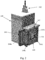
- an additive manufacturing apparatus comprises a build chamber 101 having therein a top plate 115 providing a surface onto which powder can be deposited and a build sleeve 117 in which a build platform 102 is movable.
- the build sleeve 117 and build platform 102 define a build volume 116 in which an object 103 is built by selective laser melting powder 104.
- the build platform 102 supports the object 103 and a powder bed 104 during the build.
- the platform 102 is lowered within the build sleeve 117 under the control of motor 119 as successive layers of the workpiece 103 are formed.
- Layers of powder are formed as the workpiece 103 is built by lowering the platform 102 and spreading powder dispensed from dispensing apparatus 108 using wiper 109.
- the dispensing apparatus 108 may be apparatus as described in WO2010/007396 .
- At least one laser module in this embodiment laser module 105 generates a laser 118 for melting the powder 104.
- the laser 118 is directed as required by a corresponding optical module 157.
- the laser beam 118 enters the chamber 101 via a window 107.
- the laser module 105 comprises a fibre laser, such as Nd YAG fibre laser.
- the laser beam enters the optical module 157 from above and is directed over the surface of the powder bed 104 by movable mirrors tiltable mirrors 150a, 150b (only one of which is shown in Figure 1 ).
- One of the mirrors 150 is tiltable to steer the laser beam in an X-direction and the other tiltable mirror 150 is tiltable to steer the laser beam in a Y-direction perpendicular to the X-direction.
- Movement of each tiltable mirror 150a, 150b is driven by a galvanometer 151a, 151b.
- a position of each galvanometer is measured by a transducer.
- the transducer is in accordance with the transducer described in US5844673 .
- the optical module 157 further comprises movable focussing optics 155 for adjusting the focal length of the corresponding laser beam.
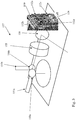
- a beam splitter 156 directs light of the laser wavelength from an input to the tiltable mirrors 150 and transmits light of other wavelengths that is emitted from the powder bed 104 to a detector module 160 via an outlet aperture 158.
- a filter (not shown) is provided just in-front of aperture 158 to filter out light of the laser wavelength such that light of the laser wavelength cannot pass out from outlet aperture 158.
- the connecting plate 159 comprises four mounting formations in the form of slots 152a, 152b, 152c and 152d for receiving mounting formations in the form of pins 164a, 164b, 164c and 164d of the detector module 160, as described in more detail below.
- the optical module further comprises an integrated optical module control unit 180 having communication interfaces for communicating with master controller 140 and the detector module 160.
- the interface is connected to an interface of the detector module 160 via a releasable cable 162.
- the detector module 160 comprises at least one detector for detecting radiation transmitted to the detector module 160 from the optical module 157.
- the detector is a photodetector 161 for detecting an integrated intensity of the transmitted light.
- the detector may alternatively or additionally comprise a further photodetector, a PSD, a CCD or CMOS camera and/or spectrometer.
- the radiation enters the detector module via a receiving inlet of the detector module 160, in this embodiment in the form of an objective lens 163.
- the objective lens 163 is mounted in an adjustment mechanism 166 in the form of a flexure for adjusting a position of the objective lens relative to a mounting position of the detector module 160 on the optical module 157.
- the detector module 160 is mounted onto the optical module 157 via four mounting pins 164a, 164b, 164c, 164d that fit into slots 152a, 152b, 152c, 152d on the optical module 157.
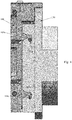
- Slots 152a and 152b have a first cross-sectional shape (as shown in Figure 5a ) and slots 152c and 152d have a second cross-sectional shape (as shown in Figure 5b ).
- the second cross-sectional shape is a slightly V-shaped cross-section having a radius of curvature smaller than the radius of curvature of the corresponding pin 164c, 164d.
- each pin 164c, 164d when pushed in to the corresponding slot 152c, 152d engages with two contact points on either side of the slot 152c, 152d defining a position in five degrees of freedom (but not defining a position of rotation about the pins 164c, 164d).
- the first cross-sectional shape has a U-shape having a depth and width such the pin 164a, 164b received therein will not engage with a valley of the U-shaped cross-section before the pins 164c, a64d engages with the side walls of their corresponding slots 152c, 152d such that mounting of the detector module is not over-constrained.
- the pins 164a, 164b engage with a rear-surface of the U-shaped cross-section to define a position relative to a rotational axis of the pins 164c, 164d.
- the pins 164a, 164b, 164c, 164d and slots 152a, 152b, 152c, 152d define a mounting position of the detector module 160 relative to a position of the optical module 157 in six degrees of freedom when the detector module 160 is mounted thereon. This position is repeatable on removable and remounting of the detector module 160 on the optical module 157.
- the detector module 160 is urged into this defined mounting position by a bolt 167 which engages with a surface of the connecting plate 159 to push the pins 164a, 164b, 164c, 164d into slots 152a, 152b, 152c, 152d.
- a seal 168 is provided around the receiving aperture 163 and is arranged to engage with the connecting plate 159 to provide a dust tight and ambient light tight seal between the outlet aperture 158 of the optical module 157 and the receiving aperture 163 of the detector module 160.
- a handle 165 is provided for an operator to grip when mounting and/or removing the detector module 160 from the optical module 157.
- a master controller 140 is in communication with modules of the additive manufacturing apparatus, namely the laser module 105, optical module 157, build platform 102, dispensing apparatus 108, wiper 109 and controller 180.
- the controller 140 controls the modules based upon commands in a build file.
- sensor values generated by sensors in the optical module 157 and the detector module 160 are sent to controller 180 and each sensor value associated with a time stamp corresponding to a time at which the sensor value was generated.
- the optical module may comprise transducers for measuring a position of the tiltable mirrors 150a, 150b and these measured positions may be packaged together with the sensor values from the detector module 160 and a time stamp and delivered as a packet to the master controller 140, as described in pending UK patent application 1707807.2 .
- the detector module 160 is aligned with the optical axis of the optical module 157 by mounting the detector module 160 on the optical module 160 or a test rig comprising corresponding mounting features and a position of the objective lens adjusted to centre collected radiation on the sensor in the detector module 160. If this is a first alignment after manufacture, the detector module 160 may be aligned at a manufacturing site and then removed for transport to a site at which the powder bed fusion apparatus will be used where it is then mounted onto/back onto the optical module 157 and realignment of the optics may not be required. In this way, a person skilled in the alignment of optics may not be required at the site of use.
- the detector module 160 may be removed from the optical module 157 for cleaning and then remounted. Realignment of the optics upon remounting of the detector module 160 may not be required as the cooperating mounting formations 164a, 164b, 164c, 164d, 152a, 152b, 152c, 152d ensure that the detector module 160 is remounted in a mounting position which is sufficiently close to the mounting position in which the optics were aligned.
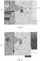
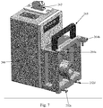
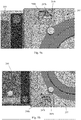
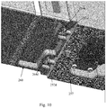
- Figures 7 to 10 show a detector module 260.
- the second embodiment differs from the first embodiment in that mounting formations of a different form are used to provide a repeatable mounting position for the detector module 260 on the optical module 257.
- the mounting formations on the detector module 260 comprise two L-shaped projections 264a and 264b at the top of the detector module 260 and two angled surfaces 264c, 264d at the bottom of the detector module 260.
- the optical module 257 comprises correspondingly shaped recesses 252a, 252b for receiving L-shaped mounting formations 264a and 264b.
- the L-shaped projections 246a and 264b comprise holes 290a, 290b therethrough for receiving bolts 267a, 267b, which engage with a threaded hole in the recess 252a, 252b.
- hole 290a has approximately a square-shaped cross-section and the hole 290b has a pentagonal-shaped cross-section.
- the mounting formations 264a, 264b, 264c, 264d, 252a, 252b, 252c, 252d define a mounting position of the detector module 260 such that the detector module 260 is returned to this mounting position on being removed from the optical module 257 and then remounted.
- a kit may be provided comprising a plurality of the detector modules 160, 260, each detector module 160, 260 of the plurality comprising a different arrangement of sensors for detecting different properties of the radiation transmitted to the detector module 160, 260.
- the plurality of detector modules comprises at least one first detector module 160, 260 comprising two photodetectors, one for detecting visible light and the second for detecting light in the infra-red spectrum, at least one second detector module comprising a position sensitive device (PSD) for detecting a position of the radiation transmitted to the detector module 160, 260 and at least one third detector module 160, 260 comprising a spectrometer for measuring an intensity of the radiation at a plurality of different wavelengths.
- PSD position sensitive device
Landscapes
- Engineering & Computer Science (AREA)
- Chemical & Material Sciences (AREA)
- Materials Engineering (AREA)
- Manufacturing & Machinery (AREA)
- Physics & Mathematics (AREA)
- Optics & Photonics (AREA)
- Mechanical Engineering (AREA)
- Health & Medical Sciences (AREA)
- Toxicology (AREA)
- Plasma & Fusion (AREA)
- General Health & Medical Sciences (AREA)
- Analytical Chemistry (AREA)
- Automation & Control Theory (AREA)
- Laser Beam Processing (AREA)
- Investigating Or Analysing Materials By Optical Means (AREA)
Claims (12)
- Laserverfestigungsvorrichtung zum Bauen von Objekten durch schichtweise Verfestigung von Material, wobei die Laserverfestigungsvorrichtung eine Bauplattform (102) zum Tragen des Objekts (103) und eines Materialbetts (104), ein optisches Modul (157; 257), das ein bewegliches Führungselement (150a, 150b) zum Richten eines Laserstrahls (118) umfasst, um Material des Materialbetts (104) zu verfestigen, und ein Detektormodul (160, 260) umfasst, das einen Sensor (161) zum Erfassen von Strahlung, die von dem Materialbett (104) emittiert und durch das bewegliche Führungselement (150a, 150b) des optischen Moduls (157; 257) an den Sensor (161) übertragen wird, wobei das Detektormodul (160, 260) abnehmbar an dem optischen Modul (157; 257) montiert ist, dadurch gekennzeichnet, dass das optische Modul (157; 257) einen Controller (180) umfasst, der eine Schnittstelle umfasst, die so angeordnet ist, dass sie lösbar mit einem elektronischen Ausgang des Detektormoduls (160; 260) gekoppelt ist, so dass der Controller (180) Sensorsignale von dem Sensor (161) des Detektormoduls (160; 260) empfangen kann, und der Controller (180) angeordnet ist, um Datenpakete zu bilden, die Steuer- oder Messdaten, die an das optische Modul (157; 257) gesendet oder von diesem erzeugt werden, und Sensordaten basierend auf den vom Detektormodul (160; 260) empfangenen Sensorsignalen umfassen.
- Laserverfestigungsvorrichtung nach Anspruch 1, wobei das optische Modul (157; 257) einen Wandler zum Messen einer Position des Führungselements (150a, 150b) umfasst und der Controller (180) angeordnet ist, um Datenpakete zu bilden, die eine durch den Wandler gemessene Position des Führungselements (150a, 150b) und die Sensordaten basierend auf den Sensorsignalen, die von dem Detektormodul (160, 260) empfangen sind, umfassen.
- Laserverfestigungsvorrichtung nach einem der Ansprüche 1 oder 2, wobei der Controller (180) angeordnet ist, um Datenpakete zu bilden, die einen gemessenen Parameter des Laserstrahls (118) und die Sensordaten basierend auf den vom Detektormodul (160; 260) empfangenen Sensorsignalen umfassen.
- Laserverfestigungsvorrichtung nach einem der vorhergehenden Ansprüche, wobei der Controller (180) angeordnet ist, um Datenpakete und eine Kennung zu bilden, die verwendet werden kann, um die Sensordaten mit Steuerdaten und/oder Messdaten in Verbindung zu setzen.
- Laserverfestigungsvorrichtung nach Anspruch 4, wobei die Kennung einen Zeitstempel umfasst.
- Laserverfestigungsvorrichtung nach einem der vorhergehenden Ansprüche, wobei das Detektormodul (160; 260) und das optische Modul (157; 257) komplementäre Montageausbildungen (152a, 152b, 152c, 152d, 164a, 164b, 164c, 164d; 252a, 252b, 252c, 252d, 264a, 264b, 264c, 264d) zum lösbaren Montieren des Detektormoduls (160; 260) an dem optischen Modul (157; 257) in einer Montageposition umfassen.
- Laserverfestigungsvorrichtung nach Anspruch 6, wobei das Detektormodul (160) ferner einen Einstellmechanismus (166) zum Einstellen einer relativen Position einer optischen Achse des Sensors (161) an die Montageposition umfasst.
- Laserverfestigungsvorrichtung nach einem der Ansprüche 6 oder 7, wobei die komplementären Montageausbildungen (152a, 152b, 152c, 152d, 164a, 164b, 164c, 164d; 252a, 252b, 252c, 252d, 264a, 264b, 264c, 264d) zum lösbaren Montieren des Detektormoduls (160; 260) an dem optischen Modul (157; 257) in einer wiederholbaren Montageposition angeordnet sind.
- Laserverfestigungsvorrichtung nach Anspruch 8, wobei die komplementären Montageausbildungen (152a, 152b, 152c, 152d, 164a, 164b, 164c, 164d; 252a, 252b, 252c, 252d, 264a, 264b, 264c, 264d) eine kinematische oder pseudokinematische Halterung bilden.
- Laserverfestigungsvorrichtung nach einem der vorhergehenden Ansprüche, wobei das optische Modul (157; 257) ein optisches Modulgehäuse umfasst, das das bewegliche Führungselement (150a, 150b) enthält, wobei das optische Modulgehäuse eine Auslassöffnung (158) darin aufweist, durch die die vom Materialbett (104) emittierte Strahlung von dem beweglichen Führungselement (150a, 150b) übertragen wird und das Detektormodul (160; 280) ein den Sensor (161) enthaltendes Detektormodulgehäuse umfasst, wobei das Detektormodulgehäuse eine darin angeordnete Empfangsöffnung (163) zum Empfangen von Strahlung aufweist, die von der Auslassöffnung (158) in dem optischen Modulgehäuse übertragen ist, wenn das Detektormodul (160; 260) an dem optischen Modul (157; 257) montiert ist.
- Laserverfestigungsvorrichtung nach Anspruch 10, wobei eines von dem Detektormodul (160; 260) und dem optischen Modul (157; 257) eine Dichtung (168) um die Empfangsöffnung (163) / Auslassöffnung (158) herum zum Eingriff mit dem anderen von dem optischen Modul (157; 257) und dem Detektormodul (160; 260) umfasst, um einen Übertragungsweg für die Strahlung vom optischen Modul (157; 257) zum Detektormodul (160; 260) gegen Staub und /oder Umgebungslicht abzudichten.
- Laserverfestigungsvorrichtung nach einem der Ansprüche 10 oder 11, wobei das optische Modulgehäuse einen Filter umfasst, um Licht einer Wellenlänge des Laserstrahls (118) daran zu hindern, durch die Auslassöffnung (158) herauszutreten.
Applications Claiming Priority (1)
| Application Number | Priority Date | Filing Date | Title |
|---|---|---|---|
| GBGB1718596.8A GB201718596D0 (en) | 2017-11-10 | 2017-11-10 | In-process monitoring in laser solidification apparatus |
Publications (2)
| Publication Number | Publication Date |
|---|---|
| EP3482909A1 EP3482909A1 (de) | 2019-05-15 |
| EP3482909B1 true EP3482909B1 (de) | 2021-09-01 |
Family
ID=60788264
Family Applications (1)
| Application Number | Title | Priority Date | Filing Date |
|---|---|---|---|
| EP18204791.0A Active EP3482909B1 (de) | 2017-11-10 | 2018-11-07 | Laserverfestigungsvorrichtung zur herstellung von gegenständen durch schichtweises härten von material |
Country Status (5)
| Country | Link |
|---|---|
| US (1) | US20200262152A1 (de) |
| EP (1) | EP3482909B1 (de) |
| CN (1) | CN111491777B (de) |
| GB (1) | GB201718596D0 (de) |
| WO (1) | WO2019092414A1 (de) |
Families Citing this family (6)
| Publication number | Priority date | Publication date | Assignee | Title |
|---|---|---|---|---|
| DE102018200566B4 (de) * | 2018-01-15 | 2021-07-15 | Fraunhofer-Gesellschaft zur Förderung der angewandten Forschung e.V. | System und Verfahren zur Überwachung der Fertigungsgenauigkeit bei der additiven Herstellung dreidimensionaler Bauteile |
| US10981328B2 (en) * | 2018-11-06 | 2021-04-20 | Brinter Oy | Modular systems and methods for performing additive manufacturing of objects |
| EP3702158A1 (de) | 2019-02-28 | 2020-09-02 | Renishaw PLC | Verbesserungen an oder im zusammenhang mit an der achse befestigten schmelzbadsensoren in einer vorrichtung zur generativen fertigung |
| EP3904946A1 (de) * | 2020-04-30 | 2021-11-03 | Raylase GmbH | Modulare ablenkeinheiten in einer spiegelsymmetrischen anordnung |
| CN115666905B (zh) | 2020-05-27 | 2026-02-10 | 速尔特技术有限公司 | 用于增材制造的模块结构 |
| JP2026505335A (ja) * | 2023-02-10 | 2026-02-13 | スリーディー システムズ インコーポレーテッド | 低弾性率物品の製造方法 |
Family Cites Families (7)
| Publication number | Priority date | Publication date | Assignee | Title |
|---|---|---|---|---|
| GB201316815D0 (en) * | 2013-09-23 | 2013-11-06 | Renishaw Plc | Additive manufacturing apparatus and method |
| CN106061714B (zh) * | 2014-01-16 | 2019-07-12 | 惠普发展公司,有限责任合伙企业 | 基于辐射率的温度确定 |
| US9925715B2 (en) * | 2014-06-30 | 2018-03-27 | General Electric Company | Systems and methods for monitoring a melt pool using a dedicated scanning device |
| DE102015000102A1 (de) * | 2015-01-14 | 2016-07-14 | Cl Schutzrechtsverwaltungs Gmbh | Vorrichtung zur generativen Herstellung dreidimensionaler Bauteile |
| CN104907562B (zh) * | 2015-06-05 | 2018-01-26 | 湖南华曙高科技有限责任公司 | 用于制造三维物体的设备 |
| WO2017085468A1 (en) * | 2015-11-16 | 2017-05-26 | Renishaw Plc | An additive manufacturing method and apparatus |
| CN109070221B (zh) * | 2016-04-25 | 2021-08-03 | 瑞尼斯豪公司 | 对增材制造设备中的多个扫描器的校准方法 |
-
2017
- 2017-11-10 GB GBGB1718596.8A patent/GB201718596D0/en not_active Ceased
-
2018
- 2018-11-07 WO PCT/GB2018/053224 patent/WO2019092414A1/en not_active Ceased
- 2018-11-07 CN CN201880073036.9A patent/CN111491777B/zh active Active
- 2018-11-07 US US16/760,014 patent/US20200262152A1/en not_active Abandoned
- 2018-11-07 EP EP18204791.0A patent/EP3482909B1/de active Active
Also Published As
| Publication number | Publication date |
|---|---|
| WO2019092414A1 (en) | 2019-05-16 |
| GB201718596D0 (en) | 2017-12-27 |
| EP3482909A1 (de) | 2019-05-15 |
| CN111491777A (zh) | 2020-08-04 |
| US20200262152A1 (en) | 2020-08-20 |
| CN111491777B (zh) | 2023-04-07 |
Similar Documents
| Publication | Publication Date | Title |
|---|---|---|
| EP3482909B1 (de) | Laserverfestigungsvorrichtung zur herstellung von gegenständen durch schichtweises härten von material | |
| US20240337592A1 (en) | Additive manufacturing apparatus and method | |
| US20170368640A1 (en) | Device for the additive production of three-dimensional components | |
| EP3538295B1 (de) | Lokalisieren von während der generativen fertigung gesammelten sensordaten | |
| JP6647375B2 (ja) | 光合波器の製造装置 | |
| DE10297255B4 (de) | Verfahren und Vorrichtung zum Überwachen und Einstellen eines Laserschweißprozesses | |
| US11993007B2 (en) | Measuring system for a device for the generative manufacturing of a three-dimensional object | |
| CN107088706B (zh) | 多点传感激光扫描加工系统 | |
| CN115943048A (zh) | 增材制造设备中的同轴熔池传感器中或与其相关的改进 | |
| CN120619383A (zh) | 将电磁辐射引导到扫描场内不同位置的光学扫描器的改进或其相关改进 | |
| CN219265490U (zh) | 一种应用于激光加工过程的激光监控仪器 | |
| WO2021032387A1 (de) | Ausrichteinheit, sensormodul umfassend dieselbe und laserbearbeitungssystem umfassend das sensormodul | |
| CN104483105B (zh) | 一种像素间串扰检测系统及方法 | |
| KR20220149027A (ko) | 레이저 파워를 모니터링하는 레이저 가공 장치 | |
| KR102291751B1 (ko) | 금속 3d프린터 모니터링 방법 및 모니터링 장치 | |
| CN115078370B (zh) | 增材制造过程监测 | |
| JP2021120187A (ja) | 積層造形装置および三次元造形物の製造方法 | |
| CN116086603A (zh) | 一种激光监控仪器的标定与光路调整、光路校准方法 | |
| KR102592154B1 (ko) | 분광기를 이용한 레이저절단 모니터링 방법 및 장치 | |
| US20210138578A1 (en) | Optical filter having dual polarization | |
| Scaggs et al. | Focal spot monitoring of a high power fiber laser |
Legal Events
| Date | Code | Title | Description |
|---|---|---|---|
| PUAI | Public reference made under article 153(3) epc to a published international application that has entered the european phase |
Free format text: ORIGINAL CODE: 0009012 |
|
| STAA | Information on the status of an ep patent application or granted ep patent |
Free format text: STATUS: THE APPLICATION HAS BEEN PUBLISHED |
|
| AK | Designated contracting states |
Kind code of ref document: A1 Designated state(s): AL AT BE BG CH CY CZ DE DK EE ES FI FR GB GR HR HU IE IS IT LI LT LU LV MC MK MT NL NO PL PT RO RS SE SI SK SM TR |
|
| AX | Request for extension of the european patent |
Extension state: BA ME |
|
| STAA | Information on the status of an ep patent application or granted ep patent |
Free format text: STATUS: REQUEST FOR EXAMINATION WAS MADE |
|
| 17P | Request for examination filed |
Effective date: 20191105 |
|
| RBV | Designated contracting states (corrected) |
Designated state(s): AL AT BE BG CH CY CZ DE DK EE ES FI FR GB GR HR HU IE IS IT LI LT LU LV MC MK MT NL NO PL PT RO RS SE SI SK SM TR |
|
| REG | Reference to a national code |
Ref country code: DE Ref legal event code: R079 Ref document number: 602018022734 Country of ref document: DE Free format text: PREVIOUS MAIN CLASS: B29C0064129000 Ipc: B29C0064393000 |
|
| GRAP | Despatch of communication of intention to grant a patent |
Free format text: ORIGINAL CODE: EPIDOSNIGR1 |
|
| STAA | Information on the status of an ep patent application or granted ep patent |
Free format text: STATUS: GRANT OF PATENT IS INTENDED |
|
| RIC1 | Information provided on ipc code assigned before grant |
Ipc: B22F 12/00 20210101ALI20210305BHEP Ipc: B22F 10/20 20210101ALI20210305BHEP Ipc: B33Y 50/02 20150101ALI20210305BHEP Ipc: B29C 64/268 20170101ALI20210305BHEP Ipc: B29C 64/153 20170101ALI20210305BHEP Ipc: B29C 64/135 20170101ALI20210305BHEP Ipc: B29C 64/393 20170101AFI20210305BHEP |
|
| INTG | Intention to grant announced |
Effective date: 20210407 |
|
| GRAS | Grant fee paid |
Free format text: ORIGINAL CODE: EPIDOSNIGR3 |
|
| GRAA | (expected) grant |
Free format text: ORIGINAL CODE: 0009210 |
|
| STAA | Information on the status of an ep patent application or granted ep patent |
Free format text: STATUS: THE PATENT HAS BEEN GRANTED |
|
| AK | Designated contracting states |
Kind code of ref document: B1 Designated state(s): AL AT BE BG CH CY CZ DE DK EE ES FI FR GB GR HR HU IE IS IT LI LT LU LV MC MK MT NL NO PL PT RO RS SE SI SK SM TR |
|
| REG | Reference to a national code |
Ref country code: GB Ref legal event code: FG4D |
|
| REG | Reference to a national code |
Ref country code: CH Ref legal event code: EP Ref country code: AT Ref legal event code: REF Ref document number: 1425782 Country of ref document: AT Kind code of ref document: T Effective date: 20210915 |
|
| REG | Reference to a national code |
Ref country code: DE Ref legal event code: R096 Ref document number: 602018022734 Country of ref document: DE |
|
| REG | Reference to a national code |
Ref country code: IE Ref legal event code: FG4D |
|
| REG | Reference to a national code |
Ref country code: LT Ref legal event code: MG9D |
|
| REG | Reference to a national code |
Ref country code: NL Ref legal event code: MP Effective date: 20210901 |
|
| PG25 | Lapsed in a contracting state [announced via postgrant information from national office to epo] |
Ref country code: NO Free format text: LAPSE BECAUSE OF FAILURE TO SUBMIT A TRANSLATION OF THE DESCRIPTION OR TO PAY THE FEE WITHIN THE PRESCRIBED TIME-LIMIT Effective date: 20211201 Ref country code: BG Free format text: LAPSE BECAUSE OF FAILURE TO SUBMIT A TRANSLATION OF THE DESCRIPTION OR TO PAY THE FEE WITHIN THE PRESCRIBED TIME-LIMIT Effective date: 20211201 Ref country code: LT Free format text: LAPSE BECAUSE OF FAILURE TO SUBMIT A TRANSLATION OF THE DESCRIPTION OR TO PAY THE FEE WITHIN THE PRESCRIBED TIME-LIMIT Effective date: 20210901 Ref country code: HR Free format text: LAPSE BECAUSE OF FAILURE TO SUBMIT A TRANSLATION OF THE DESCRIPTION OR TO PAY THE FEE WITHIN THE PRESCRIBED TIME-LIMIT Effective date: 20210901 Ref country code: ES Free format text: LAPSE BECAUSE OF FAILURE TO SUBMIT A TRANSLATION OF THE DESCRIPTION OR TO PAY THE FEE WITHIN THE PRESCRIBED TIME-LIMIT Effective date: 20210901 Ref country code: FI Free format text: LAPSE BECAUSE OF FAILURE TO SUBMIT A TRANSLATION OF THE DESCRIPTION OR TO PAY THE FEE WITHIN THE PRESCRIBED TIME-LIMIT Effective date: 20210901 Ref country code: SE Free format text: LAPSE BECAUSE OF FAILURE TO SUBMIT A TRANSLATION OF THE DESCRIPTION OR TO PAY THE FEE WITHIN THE PRESCRIBED TIME-LIMIT Effective date: 20210901 Ref country code: RS Free format text: LAPSE BECAUSE OF FAILURE TO SUBMIT A TRANSLATION OF THE DESCRIPTION OR TO PAY THE FEE WITHIN THE PRESCRIBED TIME-LIMIT Effective date: 20210901 |
|
| REG | Reference to a national code |
Ref country code: AT Ref legal event code: MK05 Ref document number: 1425782 Country of ref document: AT Kind code of ref document: T Effective date: 20210901 |
|
| PG25 | Lapsed in a contracting state [announced via postgrant information from national office to epo] |
Ref country code: PL Free format text: LAPSE BECAUSE OF FAILURE TO SUBMIT A TRANSLATION OF THE DESCRIPTION OR TO PAY THE FEE WITHIN THE PRESCRIBED TIME-LIMIT Effective date: 20210901 Ref country code: LV Free format text: LAPSE BECAUSE OF FAILURE TO SUBMIT A TRANSLATION OF THE DESCRIPTION OR TO PAY THE FEE WITHIN THE PRESCRIBED TIME-LIMIT Effective date: 20210901 Ref country code: GR Free format text: LAPSE BECAUSE OF FAILURE TO SUBMIT A TRANSLATION OF THE DESCRIPTION OR TO PAY THE FEE WITHIN THE PRESCRIBED TIME-LIMIT Effective date: 20211202 |
|
| PG25 | Lapsed in a contracting state [announced via postgrant information from national office to epo] |
Ref country code: AT Free format text: LAPSE BECAUSE OF FAILURE TO SUBMIT A TRANSLATION OF THE DESCRIPTION OR TO PAY THE FEE WITHIN THE PRESCRIBED TIME-LIMIT Effective date: 20210901 |
|
| PG25 | Lapsed in a contracting state [announced via postgrant information from national office to epo] |
Ref country code: IS Free format text: LAPSE BECAUSE OF FAILURE TO SUBMIT A TRANSLATION OF THE DESCRIPTION OR TO PAY THE FEE WITHIN THE PRESCRIBED TIME-LIMIT Effective date: 20220101 Ref country code: SM Free format text: LAPSE BECAUSE OF FAILURE TO SUBMIT A TRANSLATION OF THE DESCRIPTION OR TO PAY THE FEE WITHIN THE PRESCRIBED TIME-LIMIT Effective date: 20210901 Ref country code: SK Free format text: LAPSE BECAUSE OF FAILURE TO SUBMIT A TRANSLATION OF THE DESCRIPTION OR TO PAY THE FEE WITHIN THE PRESCRIBED TIME-LIMIT Effective date: 20210901 Ref country code: RO Free format text: LAPSE BECAUSE OF FAILURE TO SUBMIT A TRANSLATION OF THE DESCRIPTION OR TO PAY THE FEE WITHIN THE PRESCRIBED TIME-LIMIT Effective date: 20210901 Ref country code: PT Free format text: LAPSE BECAUSE OF FAILURE TO SUBMIT A TRANSLATION OF THE DESCRIPTION OR TO PAY THE FEE WITHIN THE PRESCRIBED TIME-LIMIT Effective date: 20220103 Ref country code: NL Free format text: LAPSE BECAUSE OF FAILURE TO SUBMIT A TRANSLATION OF THE DESCRIPTION OR TO PAY THE FEE WITHIN THE PRESCRIBED TIME-LIMIT Effective date: 20210901 Ref country code: EE Free format text: LAPSE BECAUSE OF FAILURE TO SUBMIT A TRANSLATION OF THE DESCRIPTION OR TO PAY THE FEE WITHIN THE PRESCRIBED TIME-LIMIT Effective date: 20210901 Ref country code: CZ Free format text: LAPSE BECAUSE OF FAILURE TO SUBMIT A TRANSLATION OF THE DESCRIPTION OR TO PAY THE FEE WITHIN THE PRESCRIBED TIME-LIMIT Effective date: 20210901 Ref country code: AL Free format text: LAPSE BECAUSE OF FAILURE TO SUBMIT A TRANSLATION OF THE DESCRIPTION OR TO PAY THE FEE WITHIN THE PRESCRIBED TIME-LIMIT Effective date: 20210901 |
|
| REG | Reference to a national code |
Ref country code: DE Ref legal event code: R097 Ref document number: 602018022734 Country of ref document: DE |
|
| PG25 | Lapsed in a contracting state [announced via postgrant information from national office to epo] |
Ref country code: MC Free format text: LAPSE BECAUSE OF FAILURE TO SUBMIT A TRANSLATION OF THE DESCRIPTION OR TO PAY THE FEE WITHIN THE PRESCRIBED TIME-LIMIT Effective date: 20210901 |
|
| REG | Reference to a national code |
Ref country code: CH Ref legal event code: PL |
|
| PLBE | No opposition filed within time limit |
Free format text: ORIGINAL CODE: 0009261 |
|
| STAA | Information on the status of an ep patent application or granted ep patent |
Free format text: STATUS: NO OPPOSITION FILED WITHIN TIME LIMIT |
|
| PG25 | Lapsed in a contracting state [announced via postgrant information from national office to epo] |
Ref country code: LU Free format text: LAPSE BECAUSE OF NON-PAYMENT OF DUE FEES Effective date: 20211107 Ref country code: IT Free format text: LAPSE BECAUSE OF FAILURE TO SUBMIT A TRANSLATION OF THE DESCRIPTION OR TO PAY THE FEE WITHIN THE PRESCRIBED TIME-LIMIT Effective date: 20210901 Ref country code: DK Free format text: LAPSE BECAUSE OF FAILURE TO SUBMIT A TRANSLATION OF THE DESCRIPTION OR TO PAY THE FEE WITHIN THE PRESCRIBED TIME-LIMIT Effective date: 20210901 Ref country code: BE Free format text: LAPSE BECAUSE OF NON-PAYMENT OF DUE FEES Effective date: 20211130 |
|
| REG | Reference to a national code |
Ref country code: BE Ref legal event code: MM Effective date: 20211130 |
|
| 26N | No opposition filed |
Effective date: 20220602 |
|
| PG25 | Lapsed in a contracting state [announced via postgrant information from national office to epo] |
Ref country code: SI Free format text: LAPSE BECAUSE OF FAILURE TO SUBMIT A TRANSLATION OF THE DESCRIPTION OR TO PAY THE FEE WITHIN THE PRESCRIBED TIME-LIMIT Effective date: 20210901 |
|
| PG25 | Lapsed in a contracting state [announced via postgrant information from national office to epo] |
Ref country code: IE Free format text: LAPSE BECAUSE OF NON-PAYMENT OF DUE FEES Effective date: 20211107 |
|
| PG25 | Lapsed in a contracting state [announced via postgrant information from national office to epo] |
Ref country code: CY Free format text: LAPSE BECAUSE OF FAILURE TO SUBMIT A TRANSLATION OF THE DESCRIPTION OR TO PAY THE FEE WITHIN THE PRESCRIBED TIME-LIMIT Effective date: 20210901 |
|
| P01 | Opt-out of the competence of the unified patent court (upc) registered |
Effective date: 20230602 |
|
| PG25 | Lapsed in a contracting state [announced via postgrant information from national office to epo] |
Ref country code: LI Free format text: LAPSE BECAUSE OF NON-PAYMENT OF DUE FEES Effective date: 20220630 Ref country code: HU Free format text: LAPSE BECAUSE OF FAILURE TO SUBMIT A TRANSLATION OF THE DESCRIPTION OR TO PAY THE FEE WITHIN THE PRESCRIBED TIME-LIMIT; INVALID AB INITIO Effective date: 20181107 Ref country code: CH Free format text: LAPSE BECAUSE OF NON-PAYMENT OF DUE FEES Effective date: 20220630 |
|
| PG25 | Lapsed in a contracting state [announced via postgrant information from national office to epo] |
Ref country code: MK Free format text: LAPSE BECAUSE OF FAILURE TO SUBMIT A TRANSLATION OF THE DESCRIPTION OR TO PAY THE FEE WITHIN THE PRESCRIBED TIME-LIMIT Effective date: 20210901 |
|
| PG25 | Lapsed in a contracting state [announced via postgrant information from national office to epo] |
Ref country code: TR Free format text: LAPSE BECAUSE OF FAILURE TO SUBMIT A TRANSLATION OF THE DESCRIPTION OR TO PAY THE FEE WITHIN THE PRESCRIBED TIME-LIMIT Effective date: 20210901 |
|
| PG25 | Lapsed in a contracting state [announced via postgrant information from national office to epo] |
Ref country code: MT Free format text: LAPSE BECAUSE OF FAILURE TO SUBMIT A TRANSLATION OF THE DESCRIPTION OR TO PAY THE FEE WITHIN THE PRESCRIBED TIME-LIMIT Effective date: 20210901 |
|
| PGFP | Annual fee paid to national office [announced via postgrant information from national office to epo] |
Ref country code: DE Payment date: 20251126 Year of fee payment: 8 |
|
| PGFP | Annual fee paid to national office [announced via postgrant information from national office to epo] |
Ref country code: GB Payment date: 20251125 Year of fee payment: 8 |
|
| PGFP | Annual fee paid to national office [announced via postgrant information from national office to epo] |
Ref country code: FR Payment date: 20251124 Year of fee payment: 8 |