EP3482875A1 - Oscillating device, superfinishing device, method of manufacturing bearing, method of manufactoring vehicle, and method of manufacturing machine - Google Patents
Oscillating device, superfinishing device, method of manufacturing bearing, method of manufactoring vehicle, and method of manufacturing machine Download PDFInfo
- Publication number
- EP3482875A1 EP3482875A1 EP18205104.5A EP18205104A EP3482875A1 EP 3482875 A1 EP3482875 A1 EP 3482875A1 EP 18205104 A EP18205104 A EP 18205104A EP 3482875 A1 EP3482875 A1 EP 3482875A1
- Authority
- EP
- European Patent Office
- Prior art keywords
- fiber
- oscillating
- oscillating device
- tubular body
- reinforced
- Prior art date
- Legal status (The legal status is an assumption and is not a legal conclusion. Google has not performed a legal analysis and makes no representation as to the accuracy of the status listed.)
- Granted
Links
Images





Classifications
-
- B—PERFORMING OPERATIONS; TRANSPORTING
- B24—GRINDING; POLISHING
- B24B—MACHINES, DEVICES, OR PROCESSES FOR GRINDING OR POLISHING; DRESSING OR CONDITIONING OF ABRADING SURFACES; FEEDING OF GRINDING, POLISHING, OR LAPPING AGENTS
- B24B35/00—Machines or devices designed for superfinishing surfaces on work, i.e. by means of abrading blocks reciprocating with high frequency
-
- B—PERFORMING OPERATIONS; TRANSPORTING
- B24—GRINDING; POLISHING
- B24B—MACHINES, DEVICES, OR PROCESSES FOR GRINDING OR POLISHING; DRESSING OR CONDITIONING OF ABRADING SURFACES; FEEDING OF GRINDING, POLISHING, OR LAPPING AGENTS
- B24B1/00—Processes of grinding or polishing; Use of auxiliary equipment in connection with such processes
-
- B—PERFORMING OPERATIONS; TRANSPORTING
- B24—GRINDING; POLISHING
- B24B—MACHINES, DEVICES, OR PROCESSES FOR GRINDING OR POLISHING; DRESSING OR CONDITIONING OF ABRADING SURFACES; FEEDING OF GRINDING, POLISHING, OR LAPPING AGENTS
- B24B19/00—Single-purpose machines or devices for particular grinding operations not covered by any other main group
- B24B19/02—Single-purpose machines or devices for particular grinding operations not covered by any other main group for grinding grooves, e.g. on shafts, in casings, in tubes, homokinetic joint elements
- B24B19/06—Single-purpose machines or devices for particular grinding operations not covered by any other main group for grinding grooves, e.g. on shafts, in casings, in tubes, homokinetic joint elements for grinding races, e.g. roller races
-
- B—PERFORMING OPERATIONS; TRANSPORTING
- B24—GRINDING; POLISHING
- B24B—MACHINES, DEVICES, OR PROCESSES FOR GRINDING OR POLISHING; DRESSING OR CONDITIONING OF ABRADING SURFACES; FEEDING OF GRINDING, POLISHING, OR LAPPING AGENTS
- B24B35/00—Machines or devices designed for superfinishing surfaces on work, i.e. by means of abrading blocks reciprocating with high frequency
- B24B35/005—Machines or devices designed for superfinishing surfaces on work, i.e. by means of abrading blocks reciprocating with high frequency for making three-dimensional objects
-
- B—PERFORMING OPERATIONS; TRANSPORTING
- B24—GRINDING; POLISHING
- B24B—MACHINES, DEVICES, OR PROCESSES FOR GRINDING OR POLISHING; DRESSING OR CONDITIONING OF ABRADING SURFACES; FEEDING OF GRINDING, POLISHING, OR LAPPING AGENTS
- B24B47/00—Drives or gearings; Equipment therefor
- B24B47/10—Drives or gearings; Equipment therefor for rotating or reciprocating working-spindles carrying grinding wheels or workpieces
- B24B47/12—Drives or gearings; Equipment therefor for rotating or reciprocating working-spindles carrying grinding wheels or workpieces by mechanical gearing or electric power
-
- F—MECHANICAL ENGINEERING; LIGHTING; HEATING; WEAPONS; BLASTING
- F16—ENGINEERING ELEMENTS AND UNITS; GENERAL MEASURES FOR PRODUCING AND MAINTAINING EFFECTIVE FUNCTIONING OF MACHINES OR INSTALLATIONS; THERMAL INSULATION IN GENERAL
- F16H—GEARING
- F16H47/00—Combinations of mechanical gearing with fluid clutches or fluid gearing
Definitions
- the present invention relates to an oscillating device and a superfinishing device provided with the oscillating device. Further, the present invention relates to a method of manufacturing a bearing using the superfinishing device, and a method of manufacturing a vehicle and a machine using the bearing manufactured by the manufacturing method.
- FIG. 14 is a perspective view illustrating a superfinishing device described in JP-A-2006-255889 .
- the superfinishing process of an inner ring raceway surface and an outer ring raceway surface is important for improving rotation performance of a bearing and takes a considerable time. Therefore, in order to improve production efficiency of the bearing, it is necessary to shorten a process time by increasing a speed of an oscillating device for oscillating a grindstone. For increasing the speed, it is necessary to reduce weights of components of the oscillating device, so that reduction in the weights of the components has been facilitated in the related art by using an aluminum alloy and the like. However, further weight reduction is strongly desired.
- an object of the present invention is to shorten a process time by further reducing weights of respective components such as a connecting rod and the like forming a connecting mechanism of an oscillating device to be incorporated in a superfinishing device to improve production efficiency of a bearing.
- the present invention provides an oscillating device, a superfinishing device, a method of manufacturing a bearing, a method of manufacturing a vehicle, and a method of manufacturing a machine as follows.
- a part or whole of the connecting rod forming the connecting mechanism of the oscillating device used for the superfinishing device, and the like is made of a fiber-reinforced resin, thereby making it possible to achieve significant weight reduction in comparison with the case of a metallic rod in the related art. Therefore, it is possible to increase a speed of the oscillating device and further the superfinishing device, thereby dramatically improving production efficiency.
- Fig. 1 is a perspective view illustrating one example of an oscillating device, and the oscillating device forms a part of a superfinishing device.
- the oscillating device illustrated in the drawing includes a motor not illustrated in the drawing and serving as a driving source, an intermediate shaft spindle 1, a connecting rod 10, a connecting arm 20, a connecting shaft 30, a grindstone holder 40, and a pressurizing cylinder 47 mounted on the grindstone holder 40.
- a grindstone 50 is mounted on the grindstone holder 40, and the grindstone 50 and a device for oscillating the grindstone 50 while pressing the grindstone against a workpiece (in this case, an outer ring raceway surface of an outer ring 60) to be processed and are called as a superfinishing device.
- a workpiece in this case, an outer ring raceway surface of an outer ring 60
- a tip 51 of the grindstone 50 is pressed against an outer ring raceway surface 61 of the outer ring 60, and this pressing is performed in such a manner that a lower end part (not illustrated) of a pressurizing member mounted on the pressurizing cylinder 47 presses a pressurizing lever 90 held in a pressurizing lever holder 80 downward in the drawing, and an upper end of the grindstone 50 is pressed by a tip of the pressurizing lever 90.
- the grindstone 50 is oscillated in an X direction in Fig. 1 by the oscillating device which will be described later.
- the rotation from the motor as the driving source is transmitted to the intermediate shaft spindle 1 through a belt V.
- the connecting rod 10 for performing an eccentric motion with a rotary shaft of the intermediate shaft spindle 1 is mounted on the intermediate shaft spindle through a shaft 2.
- the connecting rod 10 includes a first through hole 11 for inserting the shaft 2 and a second through hole 12 for inserting a shaft 21 for being connected to a connecting arm 20, and bearings (not illustrated) are inserted into the respective through holes 11 and 12.
- the shaft 21 for being connected to the connecting rod 10 is inserted into a through hole 25 in the connecting arm 20. Further, the connecting shaft 30 is mounted on the connecting arm 20 so as to extend to a side of the grindstone holder 40 in parallel with the shaft 21. Additionally, the grindstone holder 40 is mounted on a tip of the connecting shaft 30.
- the connecting rod 10 performs the eccentric motion with respect to an axis of the intermediate shaft spindle I by the rotation of the motor, and the shaft 21 of the connecting arm 20 connected to the connecting rod 10 oscillates around an axial line of the connecting shaft 30. Therefore, the connecting shaft 30 is reciprocally rotated centering on the axial line at a predetermined angle in the X direction illustrated in the drawing.
- the grindstone holder 40 is also reciprocally rotated in the same direction in accordance with the reciprocating rotation of the connecting shaft 30, and the grindstone 50 is finally reciprocated in the same direction, thereby performing oscillation as illustrated in Fig. 2 .
- a portion formed by the connecting rod 10, the connecting arm 20, the connecting shaft 30, and the grindstone holder 40 is referred to as a "connecting mechanism".
- a connecting mechanism a portion formed by the connecting rod 10, the connecting arm 20, the connecting shaft 30, and the grindstone holder 40 is referred to as a "connecting mechanism".
- at least one, and desirably, all of the connecting rod 10, the connecting arm 20, the connecting shaft 30, and the grindstone holder 40 forming the connecting mechanism is made of a fiber-reinforced resin including a reinforced fiber and a binder resin. Even though these components have been made of metal so far, it is possible to dramatically achieve weight reduction by the components made of the fiber-reinforced resin, thereby making it possible to drive at a high speed. Further, even though the driving is performed at the high speed, vibration, noise, and the like are lower than those made of metal, thereby greatly improving a working environment.
- the high speed of the connecting rod 10 leads to the high speed of the oscillation of the grindstone holder 40, thereby increasing an effect of the weight reduction. Further, even in the superfinishing device provided with the oscillating device, an oscillating motion of the grindstone 50 can be performed with the high speed, thereby contributing to shortening a process time.
- a connecting rod illustrated in Figs. 3A and 3B is defined as 10A
- a connecting rod illustrated in Fig. 4 is defined as 10B
- a connecting rod illustrated in Fig. 5A is defined as 10C.
- sleeves 15 and 16 made of metal such as aluminum, and the like are fitted thereinto and integrated therewith in order to fit bearings (not illustrated) into the first through hole 11 for being connected to the intermediate shaft spindle I and the second through hole 12 for being connected to the connecting arm 20.
- the sleeves 15 and 16 are more superior in strength.
- the connecting rod 10A illustrated in Fig. 3A has a configuration in which a plurality of thin plates 10a made of the fiber-reinforced resin are laminated; the thin plates are bonded to each other to form a prismatic column having a predetermined thickness; and the first through hole 11 and the second through hole 12 are opened, whereby the sleeves 15 and 16 are inserted thereinto.
- an orientation direction of the reinforced fiber is schematically illustrated in Fig. 3B , it is desirable to orient the reinforced fiber radially outward from a center of the surface in consideration of strength. In this oriented state, the reinforced fiber is oriented in a radial direction of the through holes 11 and 12.
- the thin plates 10a in which the reinforced fibers are oriented in one direction may be laminated by being intersected with each other at upper and lower layers at a predetermined angle (for example, 45° or 90°).
- the orientation direction of the reinforced fiber in the thin plate 10a made of the fiber-reinforced resin is the orientation illustrated in Fig. 3B .
- a weight of the connecting rod 10A made of the fiber-reinforced resin can be about 40% reduced in comparison with that of a connecting rod made of aluminum of the same shape.
- the connecting rod 10B illustrated in Fig. 4 is formed by providing a cavity 17 between the through holes 11 and 12 with respect to the connecting rod 10A illustrated in Fig. 3A , thereby further achieving weight reduction by the extent of the cavity 17. Further, an opening area of the cavity 17, the number thereof, and a formation position thereof are appropriately set in consideration of the strength of the connecting rod 10B.
- the connecting rod 10C illustrated in Fig. 5A has a configuration in which blocks 18 and 19 made of the fiber-reinforced resin are inserted into openings at opposite ends of a rectangular tubular part 10' in which the first through hole 11 and the second through hole 12 are opened, thereby closing the openings thereof.
- the rectangular tubular part 10' is formed by boring the first through hole 11 and the second through hole 12 in a wound material around which a thin plate made of the fiber-reinforced resin is wound.
- a configuration of the rectangular tubular part 10' is not limited thereto, for example, a filament made of a reinforced fiber which is impregnated with the binder resin is wound a number of times along a longitudinal direction of a prism-shaped core material, and the binder resin is cured, after which the core material is pulled out and molded, and the first through hole 11 and the second through hole 12 may be bored.
- the blocks 18 and 19 made of the fiber-reinforced resin are members formed in block shapes by laminating the thin plates made of the fiber-reinforced resin.
- the rectangular tubular part 10' made of the fiber-reinforced resin is hollow, and the weight can be further reduced in comparison with the connecting rod 10B illustrated in Fig. 4 .
- the rectangular tubular part 10' is reinforced by the blocks 18 and 19, thereby having no problem in consideration of the strength.
- the blocks 18 and 19 are laminated with the thin plates 10a, and a form of laminating the thin plates 10a in an inserting direction of the blocks 18 and 19 as illustrated in Fig. 5C is more desirable than a form of laminating the thin plates 10a in a direction orthogonal to the inserting direction of the blocks 18 and 19 as illustrated in Fig. 5B .
- a lamination style illustrated in Fig. 5B when the openings of the connecting rod 10C are closed with the blocks 18 and 19, end surfaces of the connecting rod 10 are laminated surfaces of the thin plates 10a.
- end surfaces of the connecting rod 10 are surfaces of the thin plates 10a.
- the thin plate 10a made of the fiber-reinforced resin results in swelling caused by water absorption and oil absorption at a thickness portion (end surface) where the reinforced fiber is exposed. Therefore, when laminated surfaces of the blocks 18 and 19 are exposed to the end surfaces of the connecting rod 10C as illustrated in Fig. 5B , the end surfaces thereof swell.
- the end surfaces of the connecting rod 10C are the surfaces of the thin plates 10a, and since the laminated surface is surrounded by the rectangular tubular part 10', the swelling of the blocks 18 and 19 can be suppressed.
- through holes 15a and 16a corresponding to the sleeves 15 and 16 may be formed in the blocks 18 and 19.
- the rectangular tubular part 10' made of the fiber-reinforced resin is hollow, and further weight reduction can be achieved in comparison with the connecting rod 10B illustrated in Fig. 4 .
- the connecting rod 10C is reinforced by the blocks 18 and 19, thereby having no problem in consideration of the strength.
- the blocks 18 and 19 illustrated in Fig. 6A are formed by laminating the thin plates 10a, and a lamination style in which a through hole 15a (16a) is formed on the end surface (laminated surface) of the laminated thin plates 10a as illustrated in Fig. 6C is more desirable than a lamination style in which the through hole 15a (16a) is formed on the surface of the laminated thin plates 10a as illustrated in Fig. 6B . That is, Fig. 6B illustrates a case where the through hole 15a (16a) is formed along a lamination direction, Fig.
- FIG. 6C illustrates a case where the through hole 15a (16a) is formed along a direction orthogonal to the lamination direction, and it is desirable that the through hole 15a (16a) is formed along the direction orthogonal to the lamination direction.
- the end surfaces of the connecting rod 10 are the laminated surfaces of the thin plates 10a.
- the end surfaces of the connecting rod 10 are the surfaces of the thin plates 10a.
- the cooling water and the processing oil are often applied to the device, and the thin plate 10a made of the fiber-reinforced resin results in the swelling caused by the water absorption and the oil absorption at the thickness portion (the end surface) where the reinforced fiber is exposed. Therefore, when the laminated surfaces of the blocks 18 and 19 are exposed to the end surfaces of the connecting rod 10C as illustrated in Fig. 6B , the end surfaces thereof swell. On the other hand, in Fig. 6C , the end surfaces of the connecting rod 10C are the surfaces of the thin plates 10a, and since the laminated surface is surrounded by the rectangular tubular part 10', the swelling of the blocks 18 and 19 can be suppressed.
- the surfaces of the connecting rods 10A to 10C can also be coated with a silicone resin as a countermeasure against the swelling caused by the cooling water and the processing oil.
- the connecting arm 20 also has the through hole (Reference sign 25 in Fig. 1 ) through which a shaft for being respectively connected to the connecting rod 10 and the connecting shaft 30 is inserted in a rectangular main body portion.
- the connecting arm 20 can be made of the fiber-reinforced resin same as those of the connecting rods 10A to 10C.
- the grindstone holder 40 can be made of the fiber-reinforced resin. As illustrated in Fig. 7 , the grindstone holder 40 extends first and second arms 42 and 45 from a mounting plate 41 for being mounted on the connecting shaft 30, and the pressurizing cylinder 47 is mounted on the tips of the arms 42 and 45.
- a block made of the fiber-reinforced resin can be subjected to cutting to be formed into a shape illustrated in the drawing, however, a method, in which respective components such as the mounting plate 41, and the like are formed of a plate material which is made of the fiber-reinforced resin, and are joined with each other with an adhesive, a bolt, and the like, thereby being assembled, is simple and desirable.
- the plate material is formed by laminating the thin plates, thereby being integrated, and a thickness direction of the plate material is a lamination direction. Further, as illustrated in Fig. 3B , it is desirable that the orientation of the reinforced fiber is also radially oriented outward from the center of the surface.
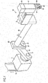
- Figs. 8A to 8E illustrate one example of an assembly method, and as illustrated in Fig. 8A , the plate material made of the fiber-reinforced resin is manufactured and cut out into a shape of the mounting plate 41.
- the first arm 42 is joined to a plate thickness portion of the mounting plate 41 so as to be perpendicular to the mounting plate 41.
- the first arm 42 is the plate material made of the fiber-reinforced resin and is cut out into a predetermined shape.
- a bottom plate 43 is joined to both inner side spaces of the mounting plate 41 and the first arm 42.
- the bottom plate 43 is the plate material made of the fiber-reinforced resin, and an oil-discharge hole 44 for flowing down and discharging the processing oil is opened at a center part.
- the second arm 45 is disposed to be opposite to the first arm 42, and is joined to the mounting plate 41 and the bottom plate 43.
- the second arm 45 is the plate material made of the fiber-reinforced resin and is cut out into a predetermined shape.
- a cylinder mounting plate 46 for mounting the pressurizing cylinder 47 is joined to respective tips of the first arm 42, the second arm 45, and the bottom plate 43.
- the cylinder mounting plate 46 is the plate material made of the fiber-reinforced resin and is cut out into a predetermined shape.
- an insertion hole 48 for inserting a pressurizing piston (not illustrated) is formed in the pressurizing cylinder 47.
- the pressurizing cylinder 47 can also be made of the fiber-reinforced resin.
- the block made of the fiber-reinforced resin may be subjected to cutting, but it is desirable that a plurality of the plate materials made of the fiber-reinforced resin are laminated in an axial direction of the insertion hole 48 to form the insertion hole 48.
- a sleeve (not illustrated) made of metal such as aluminum, and the like may be fitted into the insertion hole 48.
- the grindstone holder 40 may be formed as illustrated in Fig. 9 .
- the grindstone holder 40 illustrated in Fig. 9 is formed by replacing the first arm 42, the second arm 45, and the bottom plate 43 of the grindstone holder illustrated in Fig. 7 with a tubular body 49.
- the tubular body 49 is formed by winding a filament made of the reinforced fiber which is impregnated with the binder resin a number of times along the longitudinal direction of the prism-shaped core material, and the binder resin is cured, after which the core material is pulled out and formed into a rectangular tubular shape.
- the mounting plate 41, the cylinder mounting plate 46, and the pressurizing cylinder 47 are fiber-reinforced resin members same as the grindstone holder 40 illustrated in Fig. 7 .
- the grindstone holder 40 illustrated in Fig. 9 is assembled as illustrated in Figs. 10A to 10C .
- the tubular body 49 is joined to a front surface of the mounting plate 41.
- the cylinder mounting plate 46 is joined so as to close the opening of the tubular body 49.
- the pressurizing cylinder 47 is mounted on the cylinder mounting plate 46, thereby completing the grindstone holder 40.
- the grindstone holders 40 illustrated in Figs. 7 and 9 are made of the fiber-reinforced resin members, the grindstone holders are lightweight but have high strength, thereby making it possible to be oscillated at a higher speed and improve process efficiency.
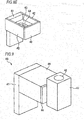
- the grindstone holders 40 illustrated in Figs. 7 and 9 are assembled by bonding the plate materials made of the fiber-reinforced resins to each other by using an adhesive, however, since the grindstone holders 40 receive vibration, there exists a concern that the strength may deteriorate at a bonded portion. Therefore, it is desirable to manufacture the grindstone holder 40 by integral molding in order to increase the strength of the bonded portion. For example, as illustrated in Fig. 11 , the melt of a resin composition including the reinforced fiber and the binder resin is injected into a mold having a cavity of a shape in which four sides of the bottom plate 43 illustrated in Figs. 7 to 8E are surrounded by peripheral walls, and then is cured, thereby making it possible to manufacture the integrated grindstone holder 40.
- a horizontal plate 43a corresponding to the bottom plate 43 is disposed approximately at a center in a height direction, and a cuboid-shaped space is formed on top and bottom surfaces of the horizontal plate 43a, wherein a peripheral wall 41a corresponds to the mounting plate 41, a peripheral wall 42a corresponds to the first arm 42, a peripheral wall 45a corresponds to the second arm 45, and a peripheral wall 46a corresponds to the cylinder mounting plate 46 respectively to surround the four sides of the horizontal plate 43a.
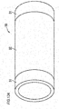
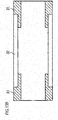
- the connecting shaft 30 can be wholly made of the fiber-reinforced resin, however, since the reinforced fiber has insufficient wear resistance, the connecting shaft 30 slides at connecting portions with the connecting arm 20 (refer to Fig. 1 ) and the mounting plate 41 (refer to Fig. 7 ) of the grindstone holder 40, and is easily worn out thereat.
- opposite ends 31 in a longitudinal direction serving as sliding portions may be made of metal, and a part 32 therebetween may be made of the fiber-reinforced resin.
- Figs. 12A to 13B opposite ends 31 in a longitudinal direction serving as sliding portions may be made of metal, and a part 32 therebetween may be made of the fiber-reinforced resin.
- a tubular body made of metal is prepared, the opposite ends 31 of the outer peripheral surface thereof are left as long as lengths corresponding to the connecting portions with the connecting arm 20 and the mounting plate 41 of the grindstone holder 40, a recess (Reference sign 32) having the same depth is provided therebetween, and the recess is filled with the reinforced fiber resin.
- the tubular body is manufactured by insert molding using a metallic tubular body as a core.
- annular members made of metal, in which recessed parts matching thickness of a tubular body made of the fiber-reinforced resin are formed on an outer peripheral surface, are fitted to opposite ends of the tubular body made of the fiber-reinforced resin corresponding to the part 32, and are integrated with each other by using an adhesive.
- the reinforced fiber there are no limitations on the reinforced fiber and the binder resin in the fiber-reinforced resin forming the above-mentioned respective members, however, as the reinforced fiber, it is desirable to be lightweight and to have a high tensile strength.
- a carbon fiber, a polyamide fiber, a boron fiber, a polyarylate fiber, a polyparaphenylene benzoxazole fiber, an ultrahigh molecular weight polyethylene fiber, and the like are suitable, and those fibers can also be mixed with each other and can be used.
- the carbon fiber is desirable.
- the reinforced fiber may be surface-treated with a sizing agent such as a urethane resin, an epoxy resin, an acrylic resin, a bismaleimide resin, and the like in order to improve adhesiveness with the binder resin.
- the binder resin an epoxy resin, a bismaleimide resin, a polyamide resin, a phenolic resin, and the like can be used, and the binder resin is selected in consideration of the adhesiveness with the reinforced fiber.
- the epoxy resin can be used in the case of the carbon fiber.
- a coating amount of the binder resin or an impregnation amount thereof is not limited, but when the amount of the binder resin is too small, the binding of the reinforced fiber is not sufficient, on the other hand, when the amount of the binder resin is too large, the amount of the fiber is too small, thereby not acquiring the sufficient strength.
- the oscillating device in which respective parts are made of the fiber-reinforced resin reduces noise as the weight thereof is reduced.
- a vibration value is reduced in comparison with the oscillating device using metallic components, and noise reduction can be actually realized even in an auditory sense.
- the present invention is not basically limited to a type and a configuration of the oscillating device itself and can be applied to various oscillating devices other than the oscillating device illustrated in Fig. 1 .
- the present invention can also be applied to the oscillating device incorporated in the superfinishing device illustrated in Fig. 14 , and for example, the crank 106, and the like can be made of the fiber-reinforced resin.
- the pressurizing piston to be inserted into the insertion hole 48 of the pressurizing cylinder 47 may be integrated by bonding a disk made of the fiber-reinforced resin to upper and lower end surfaces of a cylinder made of the fiber-reinforced resin.
- the pressurizing lever holder 80 can also be made of the fiber-reinforced resin. It is possible to achieve the weight reduction of the superfinishing device as a whole in addition to the oscillating device by making those components with the fiber-reinforced resin.
- the bearing can be manufactured by polishing the raceway surface using the above-mentioned superfinishing device, however, the present invention also includes a method of manufacturing the bearing including such a process of processing a raceway surface as the scope of the present invention.
- the present invention also includes a method of manufacturing a vehicle or various machines including manufacturing a bearing by the above-mentioned method of manufacturing the bearing as the scope of the present invention.
- the machine includes a machine operated by human power as well as electric power.
- the present invention is a technology useful for shortening a process time, and further improving productivity of a bearing by reducing the weight of an oscillating device.
Landscapes
- Engineering & Computer Science (AREA)
- Mechanical Engineering (AREA)
- General Engineering & Computer Science (AREA)
- Shafts, Cranks, Connecting Bars, And Related Bearings (AREA)
- Finish Polishing, Edge Sharpening, And Grinding By Specific Grinding Devices (AREA)
Abstract
Description
- The present invention relates to an oscillating device and a superfinishing device provided with the oscillating device. Further, the present invention relates to a method of manufacturing a bearing using the superfinishing device, and a method of manufacturing a vehicle and a machine using the bearing manufactured by the manufacturing method.
- For example, in a superfinishing process of an inner ring raceway surface or an outer ring raceway surface of a bearing, while pressing a grindstone against the inner ring raceway surface or the outer ring raceway surface, the grindstone is oscillated and simultaneously the inner ring or the outer ring is rotated.
- Such a process relating to a grindstone is performed using a superfinishing device provided with an oscillating device.
Fig. 14 is a perspective view illustrating a superfinishing device described inJP-A-2006-255889 - In the superfinishing device illustrated in the drawing, rotation of a
motor 101 is transmitted to anintermediate shaft 103 through abelt 102. Acrank 106 is connected to theintermediate shaft 103 through aneccentric pin 105, and an eccentric motion of thecrank 106 is transmitted to agrindstone spindle 107, thereby oscillating agrindstone 110 mounted on atip arm 108 of thegrindstone spindle 107. Thegrindstone 110 is pressed against an inner ring raceway surface of aninner ring 111 to superfinish the inner ring raceway surface by oscillating thegrindstone 110 while rotating theinner ring 111. Further, a device for oscillating thegrindstone 110 is referred to as the oscillating device. - The superfinishing process of an inner ring raceway surface and an outer ring raceway surface is important for improving rotation performance of a bearing and takes a considerable time. Therefore, in order to improve production efficiency of the bearing, it is necessary to shorten a process time by increasing a speed of an oscillating device for oscillating a grindstone. For increasing the speed, it is necessary to reduce weights of components of the oscillating device, so that reduction in the weights of the components has been facilitated in the related art by using an aluminum alloy and the like. However, further weight reduction is strongly desired.
- Accordingly, an object of the present invention is to shorten a process time by further reducing weights of respective components such as a connecting rod and the like forming a connecting mechanism of an oscillating device to be incorporated in a superfinishing device to improve production efficiency of a bearing.
- In order to solve the above-mentioned problems, the present invention provides an oscillating device, a superfinishing device, a method of manufacturing a bearing, a method of manufacturing a vehicle, and a method of manufacturing a machine as follows.
- (1) An oscillating device including: a driving source; an oscillating member which performs an oscillating motion; and a connecting mechanism which converts a rotational motion of the driving source into an oscillating motion and transmits the oscillating motion to the oscillating member, wherein the connecting mechanism includes a component provided with a tubular body made of a fiber-reinforced resin, and a block made of a fiber-reinforced resin is inserted into the tubular body.
- (2) The oscillating device according to (I), wherein the tubular body is a wound material formed by winding a thin plate, and the block is a laminated body formed by laminating the thin plates.
- (3) The oscillating device according to (I), wherein a lamination direction of the thin plates in the block and an inserting direction of the block into the tubular body are the same.
- (4) The oscillating device according to (I), wherein the tubular body is a rectangular parallelepiped and has a symmetrical shape in a longitudinal direction.
- (5) The oscillating device according to (1), wherein a through hole penetrating through the tubular body and the block is formed.
- (6) The oscillating device according to (5), wherein the block is a laminated body formed of thin plates made of a fiber-reinforced resin, and the through hole is formed in a direction orthogonal to a lamination direction.
- (7) The oscillating device according to (5) or (6), wherein a metallic sleeve is inserted into the through hole.
- (8) The oscillating device according to (1), wherein the tubular body includes a hollow portion.
- (9) The oscillating device according to (8), wherein the hollow portion is a tubular body formed by binding a wound material of a filament of a reinforced fiber with a binder resin.
- (10) The oscillating device according to (1), wherein the tubular body is an assembly in which plate materials made of a fiber-reinforced resin are combined and bonded to each other.
- (11) The oscillating device according to (10), wherein the plate material is a plate material in which the reinforced fiber is radially oriented outward form a center of a surface thereof.
- (12) The oscillating device according to (I), wherein the tubular body includes a first through hole for inserting a shaft eccentric to a rotary shaft of the driving source therethrough, and a second through hole for connecting other components forming the connecting mechanism thereto through another shaft, the tubular body is formed by binding a wound material of the reinforced fiber with the binder resin, the blocks made of the fiber-reinforced resin are inserted into openings at opposite ends of the tubular body to close the openings, and the first through hole and the second through hole are formed to penetrate through the tubular body and the block.
- (13) The oscillating device according to (12), wherein the block is a laminated body formed of thin plates made of a fiber-reinforced resin, and the through hole is formed in a direction orthogonal to a lamination direction.
- (14) The oscillating device according to (1) or (12), wherein the connecting mechanism includes a holding component for holding the oscillating member, and the holding component is an assembly in which plate materials made of the fiber-reinforced resin are bonded to each other.
- (15) The oscillating device according to (1) or (12), wherein the connecting mechanism includes a holding component for holding the oscillating member, and a part or whole of a component forming the holding component is a tubular body formed by binding a wound material of a filament of the reinforced fiber with the binder resin.
- (16) The oscillating device according to any one of (1) to (15), wherein at least a portion where the filament of the reinforced fiber is exposed includes a coating layer made of a silicone resin.
- (17) A superfinishing device including the oscillating device according to any one of (1) to (16).
- (18) A method of manufacturing a bearing, including polishing a raceway surface using the superfinishing device according to (17).
- (19) A method of manufacturing a vehicle, including manufacturing a bearing by the method of manufacturing the bearing according to (18).
- (20) A method of manufacturing a machine, including manufacturing a bearing by the method of manufacturing the bearing according to (18).
- According to the present invention, a part or whole of the connecting rod forming the connecting mechanism of the oscillating device used for the superfinishing device, and the like is made of a fiber-reinforced resin, thereby making it possible to achieve significant weight reduction in comparison with the case of a metallic rod in the related art. Therefore, it is possible to increase a speed of the oscillating device and further the superfinishing device, thereby dramatically improving production efficiency.
- Further, when increasing the speed thereof, vibration and noise are reduced in comparison with the case of the metallic rod, thereby having an advantage of improving a working environment.
-
-
Fig. 1 is a perspective view illustrating one example of an oscillating device. -
Fig. 2 is a view for describing an oscillatory motion of a grindstone. -
Fig. 3A is a perspective view illustrating a connecting rod formed by laminating thin plates made of a fiber-reinforced resin andFig. 3B is a schematic view for describing an orientation direction of a reinforced fiber. -
Fig. 4 is a view in which a cavity is formed in the connecting rod ofFigs. 3A and 3B . -
Fig. 5A is an exploded perspective view illustrating the connecting rod provided with a rectangular tubular part made of a fiber-reinforced resin, andFigs. 5B and 5C are schematic views for describing a lamination style of thin plates in a block. -
Fig. 6A is an exploded perspective view illustrating the connecting rod provided with the rectangular tubular part made of a fiber-reinforced resin, andFigs. 6B and 6C are schematic views for describing the lamination style of the thin plates in the block. -
Fig. 7 is a perspective view illustrating a whole structure of a grindstone holder. -
Figs. 8A to 8E illustrate an assembly view of the grindstone holder inFig. 7 . -
Fig. 9 is a view illustrating another example of a grindstone holder and a perspective view illustrating a whole structure thereof. -
Figs. 10A to 10C illustrate an assembly view of the grindstone holder inFig. 9 . -
Fig. 11 is a perspective view illustrating another example of a grindstone holder. -
Fig. 12A is a perspective view illustrating one example of a connecting shaft andFig. 12B is a cross sectional view thereof. -
Fig. 13A is a perspective view illustrating another example of a connecting shaft andFig. 13B is a cross sectional view thereof. -
Fig. 14 is a perspective view illustrating a superfinishing device described inJP-A-2006-255889 - Hereinafter, the present invention will be described in detail with reference to the drawings.
-
Fig. 1 is a perspective view illustrating one example of an oscillating device, and the oscillating device forms a part of a superfinishing device. The oscillating device illustrated in the drawing includes a motor not illustrated in the drawing and serving as a driving source, an intermediate shaft spindle 1, a connectingrod 10, a connectingarm 20, a connectingshaft 30, agrindstone holder 40, and a pressurizingcylinder 47 mounted on thegrindstone holder 40. - Further, a
grindstone 50 is mounted on thegrindstone holder 40, and thegrindstone 50 and a device for oscillating the grindstone 50 while pressing the grindstone against a workpiece (in this case, an outer ring raceway surface of an outer ring 60) to be processed and are called as a superfinishing device. As illustrated inFig. 2 , atip 51 of thegrindstone 50 is pressed against an outerring raceway surface 61 of theouter ring 60, and this pressing is performed in such a manner that a lower end part (not illustrated) of a pressurizing member mounted on the pressurizingcylinder 47 presses a pressurizinglever 90 held in a pressurizinglever holder 80 downward in the drawing, and an upper end of thegrindstone 50 is pressed by a tip of the pressurizinglever 90. Thegrindstone 50 is oscillated in an X direction inFig. 1 by the oscillating device which will be described later. Then, while thetip 51 is pressed against the outerring raceway surface 61, a reciprocating motion is performed to the right and left in the drawing in a circular arc shape along a groove shape of the outerring raceway surface 61. On the other hand, theouter ring 60 rotates in a circumferential direction, and the outerring raceway surface 61 is polished by theoscillating grindstone 50. - When describing respective components forming the oscillating device in detail, the rotation from the motor as the driving source is transmitted to the intermediate shaft spindle 1 through a belt V. The connecting
rod 10 for performing an eccentric motion with a rotary shaft of the intermediate shaft spindle 1 is mounted on the intermediate shaft spindle through ashaft 2. As illustrated inFigs. 3A to 5C , the connectingrod 10 includes a first throughhole 11 for inserting theshaft 2 and a second throughhole 12 for inserting ashaft 21 for being connected to a connectingarm 20, and bearings (not illustrated) are inserted into the respective throughholes - The
shaft 21 for being connected to the connectingrod 10 is inserted into a throughhole 25 in the connectingarm 20. Further, the connectingshaft 30 is mounted on the connectingarm 20 so as to extend to a side of thegrindstone holder 40 in parallel with theshaft 21. Additionally, thegrindstone holder 40 is mounted on a tip of the connectingshaft 30. - Then, the connecting
rod 10 performs the eccentric motion with respect to an axis of the intermediate shaft spindle I by the rotation of the motor, and theshaft 21 of the connectingarm 20 connected to the connectingrod 10 oscillates around an axial line of the connectingshaft 30. Therefore, the connectingshaft 30 is reciprocally rotated centering on the axial line at a predetermined angle in the X direction illustrated in the drawing. Thegrindstone holder 40 is also reciprocally rotated in the same direction in accordance with the reciprocating rotation of the connectingshaft 30, and thegrindstone 50 is finally reciprocated in the same direction, thereby performing oscillation as illustrated inFig. 2 . - In the present invention, a portion formed by the connecting
rod 10, the connectingarm 20, the connectingshaft 30, and thegrindstone holder 40 is referred to as a "connecting mechanism". Then, at least one, and desirably, all of the connectingrod 10, the connectingarm 20, the connectingshaft 30, and thegrindstone holder 40 forming the connecting mechanism is made of a fiber-reinforced resin including a reinforced fiber and a binder resin. Even though these components have been made of metal so far, it is possible to dramatically achieve weight reduction by the components made of the fiber-reinforced resin, thereby making it possible to drive at a high speed. Further, even though the driving is performed at the high speed, vibration, noise, and the like are lower than those made of metal, thereby greatly improving a working environment. - Further, it is desirable that all of these components are made of the fiber-reinforced resin, however, in consideration of strength, it is also possible to change a part of the components to another material such as metal, and the like. Additionally, a ratio between a portion made of the fiber-reinforced resin and a portion made of another material is arbitrary, and the ratio therebetween is appropriately set in consideration of the weight reduction and the strength according to the parts.
- Particularly, the high speed of the connecting
rod 10 leads to the high speed of the oscillation of thegrindstone holder 40, thereby increasing an effect of the weight reduction. Further, even in the superfinishing device provided with the oscillating device, an oscillating motion of thegrindstone 50 can be performed with the high speed, thereby contributing to shortening a process time. - A case where the connecting
rod 10 is made of the fiber-reinforced resin will be described with reference toFigs. 3A to 5C . For the convenience of description, a connecting rod illustrated inFigs. 3A and 3B is defined as 10A, a connecting rod illustrated inFig. 4 is defined as 10B, and a connecting rod illustrated inFig. 5A is defined as 10C. Further, in the connectingrods 10A to 10C,sleeves hole 11 for being connected to the intermediate shaft spindle I and the second throughhole 12 for being connected to the connectingarm 20. It is possible to improve the smoothness of the surface by forming thesleeves holes metallic sleeves - The connecting
rod 10A illustrated inFig. 3A has a configuration in which a plurality ofthin plates 10a made of the fiber-reinforced resin are laminated; the thin plates are bonded to each other to form a prismatic column having a predetermined thickness; and the first throughhole 11 and the second throughhole 12 are opened, whereby thesleeves Fig. 3B , it is desirable to orient the reinforced fiber radially outward from a center of the surface in consideration of strength. In this oriented state, the reinforced fiber is oriented in a radial direction of the throughholes - In addition to radially orienting the reinforced fiber, the
thin plates 10a in which the reinforced fibers are oriented in one direction may be laminated by being intersected with each other at upper and lower layers at a predetermined angle (for example, 45° or 90°). - Further, even in the descriptions hereinafter, it is desirable that the orientation direction of the reinforced fiber in the
thin plate 10a made of the fiber-reinforced resin is the orientation illustrated inFig. 3B . - A weight of the connecting
rod 10A made of the fiber-reinforced resin can be about 40% reduced in comparison with that of a connecting rod made of aluminum of the same shape. - The connecting
rod 10B illustrated inFig. 4 is formed by providing acavity 17 between the throughholes rod 10A illustrated inFig. 3A , thereby further achieving weight reduction by the extent of thecavity 17. Further, an opening area of thecavity 17, the number thereof, and a formation position thereof are appropriately set in consideration of the strength of the connectingrod 10B. - The connecting
rod 10C illustrated inFig. 5A has a configuration in which blocks 18 and 19 made of the fiber-reinforced resin are inserted into openings at opposite ends of a rectangular tubular part 10' in which the first throughhole 11 and the second throughhole 12 are opened, thereby closing the openings thereof. The rectangular tubular part 10' is formed by boring the first throughhole 11 and the second throughhole 12 in a wound material around which a thin plate made of the fiber-reinforced resin is wound. Further, a configuration of the rectangular tubular part 10' is not limited thereto, for example, a filament made of a reinforced fiber which is impregnated with the binder resin is wound a number of times along a longitudinal direction of a prism-shaped core material, and the binder resin is cured, after which the core material is pulled out and molded, and the first throughhole 11 and the second throughhole 12 may be bored. Theblocks rod 10C, the rectangular tubular part 10' made of the fiber-reinforced resin is hollow, and the weight can be further reduced in comparison with the connectingrod 10B illustrated inFig. 4 . Further, the rectangular tubular part 10' is reinforced by theblocks blocks thin plates 10a, and a form of laminating thethin plates 10a in an inserting direction of theblocks Fig. 5C is more desirable than a form of laminating thethin plates 10a in a direction orthogonal to the inserting direction of theblocks Fig. 5B . In the case of a lamination style illustrated inFig. 5B , when the openings of the connectingrod 10C are closed with theblocks rod 10 are laminated surfaces of thethin plates 10a. On the other hand, in the case of a lamination style illustrated inFig. 5C , end surfaces of the connectingrod 10 are surfaces of thethin plates 10a. In the superfinishing device provided with the oscillating device, cooling water and processing oil are often applied to the device, and thethin plate 10a made of the fiber-reinforced resin results in swelling caused by water absorption and oil absorption at a thickness portion (end surface) where the reinforced fiber is exposed. Therefore, when laminated surfaces of theblocks rod 10C as illustrated inFig. 5B , the end surfaces thereof swell. On the other hand, inFig. 5C , the end surfaces of the connectingrod 10C are the surfaces of thethin plates 10a, and since the laminated surface is surrounded by the rectangular tubular part 10', the swelling of theblocks - Further, as illustrated in
Figs. 6A to 6C , throughholes sleeves blocks rod 10C, in the same manner as that ofFigs. 5A to 5C , the rectangular tubular part 10' made of the fiber-reinforced resin is hollow, and further weight reduction can be achieved in comparison with the connectingrod 10B illustrated inFig. 4 . Further, the connectingrod 10C is reinforced by theblocks - The
blocks Fig. 6A are formed by laminating thethin plates 10a, and a lamination style in which a throughhole 15a (16a) is formed on the end surface (laminated surface) of the laminatedthin plates 10a as illustrated inFig. 6C is more desirable than a lamination style in which the throughhole 15a (16a) is formed on the surface of the laminatedthin plates 10a as illustrated inFig. 6B . That is,Fig. 6B illustrates a case where the throughhole 15a (16a) is formed along a lamination direction,Fig. 6C illustrates a case where the throughhole 15a (16a) is formed along a direction orthogonal to the lamination direction, and it is desirable that the throughhole 15a (16a) is formed along the direction orthogonal to the lamination direction. In the case of the lamination style illustrated inFig. 6B , when the openings of the connectingrod 10C are closed with theblocks rod 10 are the laminated surfaces of thethin plates 10a. On the other hand, in the case of the lamination style illustrated inFig. 6C , the end surfaces of the connectingrod 10 are the surfaces of thethin plates 10a. In the superfinishing device provided with the oscillating device, the cooling water and the processing oil are often applied to the device, and thethin plate 10a made of the fiber-reinforced resin results in the swelling caused by the water absorption and the oil absorption at the thickness portion (the end surface) where the reinforced fiber is exposed. Therefore, when the laminated surfaces of theblocks rod 10C as illustrated inFig. 6B , the end surfaces thereof swell. On the other hand, inFig. 6C , the end surfaces of the connectingrod 10C are the surfaces of thethin plates 10a, and since the laminated surface is surrounded by the rectangular tubular part 10', the swelling of theblocks - Further, the surfaces of the connecting
rods 10A to 10C can also be coated with a silicone resin as a countermeasure against the swelling caused by the cooling water and the processing oil. - Further, in the same manner as that of the connecting
rod 10, the connectingarm 20 also has the through hole (Reference sign 25 inFig. 1 ) through which a shaft for being respectively connected to the connectingrod 10 and the connectingshaft 30 is inserted in a rectangular main body portion. Although not illustrated, the connectingarm 20 can be made of the fiber-reinforced resin same as those of the connectingrods 10A to 10C. - Further, the
grindstone holder 40 can be made of the fiber-reinforced resin. As illustrated inFig. 7 , thegrindstone holder 40 extends first andsecond arms plate 41 for being mounted on the connectingshaft 30, and the pressurizingcylinder 47 is mounted on the tips of thearms plate 41, and the like are formed of a plate material which is made of the fiber-reinforced resin, and are joined with each other with an adhesive, a bolt, and the like, thereby being assembled, is simple and desirable. Further, the plate material is formed by laminating the thin plates, thereby being integrated, and a thickness direction of the plate material is a lamination direction. Further, as illustrated inFig. 3B , it is desirable that the orientation of the reinforced fiber is also radially oriented outward from the center of the surface. -
Figs. 8A to 8E illustrate one example of an assembly method, and as illustrated inFig. 8A , the plate material made of the fiber-reinforced resin is manufactured and cut out into a shape of the mountingplate 41. - Next, as illustrated in
Fig. 8B , thefirst arm 42 is joined to a plate thickness portion of the mountingplate 41 so as to be perpendicular to the mountingplate 41. Thefirst arm 42 is the plate material made of the fiber-reinforced resin and is cut out into a predetermined shape. - Next, as illustrated in
Fig. 8C , abottom plate 43 is joined to both inner side spaces of the mountingplate 41 and thefirst arm 42. Thebottom plate 43 is the plate material made of the fiber-reinforced resin, and an oil-discharge hole 44 for flowing down and discharging the processing oil is opened at a center part. - Next, as illustrated in
Fig. 8D , thesecond arm 45 is disposed to be opposite to thefirst arm 42, and is joined to the mountingplate 41 and thebottom plate 43. Thesecond arm 45 is the plate material made of the fiber-reinforced resin and is cut out into a predetermined shape. - As illustrated in
Fig. 8E , acylinder mounting plate 46 for mounting the pressurizingcylinder 47 is joined to respective tips of thefirst arm 42, thesecond arm 45, and thebottom plate 43. Thecylinder mounting plate 46 is the plate material made of the fiber-reinforced resin and is cut out into a predetermined shape. - Further, as illustrated in
Fig. 7 , aninsertion hole 48 for inserting a pressurizing piston (not illustrated) is formed in the pressurizingcylinder 47. In the present invention, the pressurizingcylinder 47 can also be made of the fiber-reinforced resin. In this case, the block made of the fiber-reinforced resin may be subjected to cutting, but it is desirable that a plurality of the plate materials made of the fiber-reinforced resin are laminated in an axial direction of theinsertion hole 48 to form theinsertion hole 48. Further, a sleeve (not illustrated) made of metal such as aluminum, and the like may be fitted into theinsertion hole 48. - The
grindstone holder 40 may be formed as illustrated inFig. 9 . Thegrindstone holder 40 illustrated inFig. 9 is formed by replacing thefirst arm 42, thesecond arm 45, and thebottom plate 43 of the grindstone holder illustrated inFig. 7 with atubular body 49. Thetubular body 49 is formed by winding a filament made of the reinforced fiber which is impregnated with the binder resin a number of times along the longitudinal direction of the prism-shaped core material, and the binder resin is cured, after which the core material is pulled out and formed into a rectangular tubular shape. Further, the mountingplate 41, thecylinder mounting plate 46, and the pressurizingcylinder 47 are fiber-reinforced resin members same as thegrindstone holder 40 illustrated inFig. 7 . - The
grindstone holder 40 illustrated inFig. 9 is assembled as illustrated inFigs. 10A to 10C . First, as illustrated inFigs. 10A and 10B , thetubular body 49 is joined to a front surface of the mountingplate 41. After that, as illustrated inFig. 10C , thecylinder mounting plate 46 is joined so as to close the opening of thetubular body 49. Then, the pressurizingcylinder 47 is mounted on thecylinder mounting plate 46, thereby completing thegrindstone holder 40. - Since all of the
grindstone holders 40 illustrated inFigs. 7 and9 are made of the fiber-reinforced resin members, the grindstone holders are lightweight but have high strength, thereby making it possible to be oscillated at a higher speed and improve process efficiency. - Further, the
grindstone holders 40 illustrated inFigs. 7 and9 are assembled by bonding the plate materials made of the fiber-reinforced resins to each other by using an adhesive, however, since thegrindstone holders 40 receive vibration, there exists a concern that the strength may deteriorate at a bonded portion. Therefore, it is desirable to manufacture thegrindstone holder 40 by integral molding in order to increase the strength of the bonded portion. For example, as illustrated inFig. 11 , the melt of a resin composition including the reinforced fiber and the binder resin is injected into a mold having a cavity of a shape in which four sides of thebottom plate 43 illustrated inFigs. 7 to 8E are surrounded by peripheral walls, and then is cured, thereby making it possible to manufacture theintegrated grindstone holder 40. In thegrindstone holder 40 acquired by the integral molding, as illustrated in the drawings, ahorizontal plate 43a corresponding to thebottom plate 43 is disposed approximately at a center in a height direction, and a cuboid-shaped space is formed on top and bottom surfaces of thehorizontal plate 43a, wherein aperipheral wall 41a corresponds to the mountingplate 41, aperipheral wall 42a corresponds to thefirst arm 42, aperipheral wall 45a corresponds to thesecond arm 45, and aperipheral wall 46a corresponds to thecylinder mounting plate 46 respectively to surround the four sides of thehorizontal plate 43a. - The connecting
shaft 30 can be wholly made of the fiber-reinforced resin, however, since the reinforced fiber has insufficient wear resistance, the connectingshaft 30 slides at connecting portions with the connecting arm 20 (refer toFig. 1 ) and the mounting plate 41 (refer toFig. 7 ) of thegrindstone holder 40, and is easily worn out thereat. Here, as illustrated inFigs. 12A to 13B , opposite ends 31 in a longitudinal direction serving as sliding portions may be made of metal, and apart 32 therebetween may be made of the fiber-reinforced resin. InFigs. 12A and12B , a tubular body made of metal is prepared, the opposite ends 31 of the outer peripheral surface thereof are left as long as lengths corresponding to the connecting portions with the connectingarm 20 and the mountingplate 41 of thegrindstone holder 40, a recess (Reference sign 32) having the same depth is provided therebetween, and the recess is filled with the reinforced fiber resin. In this case, the tubular body is manufactured by insert molding using a metallic tubular body as a core. - Further, in
Figs. 13A and13B , annular members (Reference sign 31) made of metal, in which recessed parts matching thickness of a tubular body made of the fiber-reinforced resin are formed on an outer peripheral surface, are fitted to opposite ends of the tubular body made of the fiber-reinforced resin corresponding to thepart 32, and are integrated with each other by using an adhesive. - There are no limitations on the reinforced fiber and the binder resin in the fiber-reinforced resin forming the above-mentioned respective members, however, as the reinforced fiber, it is desirable to be lightweight and to have a high tensile strength. For example, a carbon fiber, a polyamide fiber, a boron fiber, a polyarylate fiber, a polyparaphenylene benzoxazole fiber, an ultrahigh molecular weight polyethylene fiber, and the like are suitable, and those fibers can also be mixed with each other and can be used. Particularly, the carbon fiber is desirable. Further, the reinforced fiber may be surface-treated with a sizing agent such as a urethane resin, an epoxy resin, an acrylic resin, a bismaleimide resin, and the like in order to improve adhesiveness with the binder resin.
- There is no limitation on an average diameter of the reinforced fiber, but when the reinforced fiber becomes too thin, the strength per one reinforced fiber is not sufficient. On the other hand, when the reinforced fiber becomes too thick, even though the strength per one reinforced fiber is increased, surface properties of a component and a part made of the acquired fiber-reinforced resin deteriorate.
- As the binder resin, an epoxy resin, a bismaleimide resin, a polyamide resin, a phenolic resin, and the like can be used, and the binder resin is selected in consideration of the adhesiveness with the reinforced fiber. For example, in the case of the carbon fiber, the epoxy resin can be used. Further, a coating amount of the binder resin or an impregnation amount thereof is not limited, but when the amount of the binder resin is too small, the binding of the reinforced fiber is not sufficient, on the other hand, when the amount of the binder resin is too large, the amount of the fiber is too small, thereby not acquiring the sufficient strength.
- In this manner, the oscillating device in which respective parts are made of the fiber-reinforced resin reduces noise as the weight thereof is reduced. In the measurement by a vibration measuring device, a vibration value is reduced in comparison with the oscillating device using metallic components, and noise reduction can be actually realized even in an auditory sense.
- As described above, the exemplary embodiments of the present invention are described, however, the present invention is not basically limited to a type and a configuration of the oscillating device itself and can be applied to various oscillating devices other than the oscillating device illustrated in
Fig. 1 . Of course, the present invention can also be applied to the oscillating device incorporated in the superfinishing device illustrated inFig. 14 , and for example, thecrank 106, and the like can be made of the fiber-reinforced resin. - Further, even in the superfinishing device, the pressurizing piston to be inserted into the
insertion hole 48 of the pressurizingcylinder 47 may be integrated by bonding a disk made of the fiber-reinforced resin to upper and lower end surfaces of a cylinder made of the fiber-reinforced resin. Further, the pressurizinglever holder 80 can also be made of the fiber-reinforced resin. It is possible to achieve the weight reduction of the superfinishing device as a whole in addition to the oscillating device by making those components with the fiber-reinforced resin. - The bearing can be manufactured by polishing the raceway surface using the above-mentioned superfinishing device, however, the present invention also includes a method of manufacturing the bearing including such a process of processing a raceway surface as the scope of the present invention.
- Further, the present invention also includes a method of manufacturing a vehicle or various machines including manufacturing a bearing by the above-mentioned method of manufacturing the bearing as the scope of the present invention. Further, the machine includes a machine operated by human power as well as electric power.
- The present invention is a technology useful for shortening a process time, and further improving productivity of a bearing by reducing the weight of an oscillating device.
Claims (20)
- An oscillating device comprising:a driving source;an oscillating member which performs an oscillating motion; anda connecting mechanism which converts a rotational motion of the driving source into an oscillating motion and transmits the oscillating motion to the oscillating member, wherein:the connecting mechanism includes a component provided with a tubular body made of a fiber-reinforced resin; anda block made of a fiber-reinforced resin is inserted into the tubular body.
- The oscillating device according to claim 1, wherein
the tubular body is a wound material formed by winding a thin plate, and the block is a laminated body formed by laminating the thin plates. - The oscillating device according to claim 1, wherein
a lamination direction of the thin plates in the block and an inserting direction of the block into the tubular body are the same. - The oscillating device according to claim 1, wherein
the tubular body is a rectangular parallelepiped and has a symmetrical shape in a longitudinal direction. - The oscillating device according to claim 1, wherein
a through hole penetrating through the tubular body and the block is formed. - The oscillating device according to claim 5, wherein
the block is a laminated body formed of thin plates made of a fiber-reinforced resin, and the through hole is formed in a direction orthogonal to a lamination direction. - The oscillating device according to claim 5 or 6, wherein
a metallic sleeve is inserted into the through hole. - The oscillating device according to claim 1, wherein
the tubular body includes a hollow portion. - The oscillating device according to claim 8, wherein
the hollow portion is a tubular body formed by binding a wound material of a filament of a reinforced fiber with a binder resin. - The oscillating device according to claim 1, wherein
the tubular body is an assembly in which plate materials made of a fiber-reinforced resin are combined and bonded to each other. - The oscillating device according to claim 10, wherein
the plate material is a plate material in which the reinforced fiber is radially oriented outward form a center of a surface thereof. - The oscillating device according to claim 1, wherein:the tubular body includes a first through hole for inserting a shaft eccentric to a rotary shaft of the driving source therethrough, and a second through hole for connecting other components forming the connecting mechanism thereto;the tubular body is formed by binding a wound material of the reinforced fiber with the binder resin, the blocks made of the fiber-reinforced resin are inserted into openings at opposite ends of the tubular body to close the openings; andthe first through hole and the second through hole are formed to penetrate through the tubular body and the block.
- The oscillating device according to claim 12, wherein
the block is a laminated body formed of thin plates made of a fiber-reinforced resin, and the through hole is formed in a direction orthogonal to a lamination direction. - The oscillating device according to claim 1 or 12, wherein
the connecting mechanism includes a holding component for holding the oscillating member, and the holding component is an assembly in which plate materials made of the fiber-reinforced resin are bonded to each other. - The oscillating device according to claim 1 or 12, wherein
the connecting mechanism includes a holding component for holding the oscillating member, and a part or whole of a component forming the holding component is a tubular body formed by binding a wound material of a filament of the reinforced fiber with the binder resin. - The oscillating device according to any one of claims 1 to 15, wherein
at least a portion where the filament of the reinforced fiber is exposed includes a coating layer made of a silicone resin. - A superfinishing device comprising the oscillating device according to any one of claims I to 16.
- A method of manufacturing a bearing, comprising polishing a raceway surface using the superfinishing device according to claim 17.
- A method of manufacturing a vehicle, comprising manufacturing a bearing by the method of manufacturing the bearing according to claim 18.
- A method of manufacturing a machine, comprising manufacturing a bearing by the method of manufacturing the bearing according to claim 18.
Applications Claiming Priority (2)
| Application Number | Priority Date | Filing Date | Title |
|---|---|---|---|
| JP2017216414 | 2017-11-09 | ||
| PCT/JP2018/016507 WO2019003611A1 (en) | 2017-06-29 | 2018-04-23 | Oscillating device, super-finishing device, method for manufacturing shaft bearing, method for manufacturing vehicle, method for manufacturing machine |
Publications (2)
| Publication Number | Publication Date |
|---|---|
| EP3482875A1 true EP3482875A1 (en) | 2019-05-15 |
| EP3482875B1 EP3482875B1 (en) | 2023-10-11 |
Family
ID=64267626
Family Applications (1)
| Application Number | Title | Priority Date | Filing Date |
|---|---|---|---|
| EP18205104.5A Active EP3482875B1 (en) | 2017-11-09 | 2018-11-08 | Oscillating device, superfinishing device, method of manufacturing bearing, method of manufactoring vehicle, and method of manufacturing machine |
Country Status (2)
| Country | Link |
|---|---|
| EP (1) | EP3482875B1 (en) |
| CN (1) | CN109968182B (en) |
Citations (4)
| Publication number | Priority date | Publication date | Assignee | Title |
|---|---|---|---|---|
| EP0829237A2 (en) * | 1996-09-12 | 1998-03-18 | Ricana Ag | Cutting apparatus with a cutting tool on an oscillating drive shaft |
| JP2006255889A (en) | 2006-05-29 | 2006-09-28 | Jtekt Corp | Super finishing equipment |
| JP2013091252A (en) * | 2011-10-26 | 2013-05-16 | Bando Chemical Industries Ltd | Carbon fiber reinforced resin-molded article, and method for manufacturing the same |
| JP2013173201A (en) * | 2012-02-24 | 2013-09-05 | Nsk Ltd | Superfinishing device |
Family Cites Families (11)
| Publication number | Priority date | Publication date | Assignee | Title |
|---|---|---|---|---|
| JPS60118487A (en) * | 1983-11-30 | 1985-06-25 | 株式会社日立製作所 | Industrial robot |
| JPH08205649A (en) * | 1995-01-31 | 1996-08-13 | Toray Ind Inc | Power transmission shaft for brush cutter, manufacturing method thereof, and operating rod for brush cutter |
| JP2007271079A (en) * | 2006-03-10 | 2007-10-18 | Toray Ind Inc | Torque transmission shaft |
| JP2010179386A (en) * | 2009-02-04 | 2010-08-19 | Toray Ind Inc | Link structure |
| CN102806667B (en) * | 2011-05-31 | 2015-08-26 | 美津浓科技股份有限公司 | The substrate reception box manufacture method of fiber-reinforced resin cramp bar |
| JP2014014883A (en) * | 2012-07-06 | 2014-01-30 | Toshiba Mach Co Ltd | Spindle device, machine tool including the same, and tool holder |
| CN102797741A (en) * | 2012-08-02 | 2012-11-28 | 中联重科股份有限公司 | Pin shaft, rotating connection structure, jib connection structure and construction machinery |
| JP6397205B2 (en) * | 2014-04-01 | 2018-09-26 | Jxtgエネルギー株式会社 | Prepreg, carbon fiber reinforced composite material, robot hand member and raw material resin composition thereof |
| CN104441723A (en) * | 2014-10-27 | 2015-03-25 | 合肥市东庐机械制造有限公司 | Lightweight integrated power transmission mechanism for punching machine |
| CN105602200B (en) * | 2016-03-09 | 2017-11-03 | 山东中恒碳纤维科技发展有限公司 | A kind of D braided composites mechanical arm and preparation method thereof |
| CN107214688A (en) * | 2017-05-25 | 2017-09-29 | 广州瑞松智能科技股份有限公司 | A kind of lightweight robot and its manufacture method |
-
2018
- 2018-11-08 EP EP18205104.5A patent/EP3482875B1/en active Active
- 2018-11-09 CN CN201811330356.6A patent/CN109968182B/en active Active
Patent Citations (4)
| Publication number | Priority date | Publication date | Assignee | Title |
|---|---|---|---|---|
| EP0829237A2 (en) * | 1996-09-12 | 1998-03-18 | Ricana Ag | Cutting apparatus with a cutting tool on an oscillating drive shaft |
| JP2006255889A (en) | 2006-05-29 | 2006-09-28 | Jtekt Corp | Super finishing equipment |
| JP2013091252A (en) * | 2011-10-26 | 2013-05-16 | Bando Chemical Industries Ltd | Carbon fiber reinforced resin-molded article, and method for manufacturing the same |
| JP2013173201A (en) * | 2012-02-24 | 2013-09-05 | Nsk Ltd | Superfinishing device |
Also Published As
| Publication number | Publication date |
|---|---|
| CN109968182B (en) | 2023-08-15 |
| CN109968182A (en) | 2019-07-05 |
| EP3482875B1 (en) | 2023-10-11 |
Similar Documents
| Publication | Publication Date | Title |
|---|---|---|
| US11638976B2 (en) | Oscillating device, superfinishing device, method of manufacturing bearing, method of manufacturing vehicle, and method of manufacturing machine | |
| DE102011102046A1 (en) | Permanent magnet excited external electrical rotor machine, rotor for such an electric machine and method for its production | |
| JP2001186734A (en) | Cage-shaped rotor using polymer resin containing high investment rate powder and method of manufacturing the same | |
| CN107431396A (en) | Rotor for motor, the motor reel attached troops to a unit and its manufacture method | |
| KR100428551B1 (en) | Method for manufacturing crank shaft of hermetic reciprocating compressor | |
| JP2008183626A (en) | Ultrasonic vibration machining method and fiber reinforced resin produced by the method | |
| EP3482875B1 (en) | Oscillating device, superfinishing device, method of manufacturing bearing, method of manufactoring vehicle, and method of manufacturing machine | |
| EP1928633B2 (en) | Base for a rotating grinding or cutting tool, and grinding or cutting tool produced therefrom | |
| JP4083680B2 (en) | High rigidity composite tool bar | |
| EP2889131A1 (en) | A Laminated Composite Structure and Related Method | |
| CN111315516B (en) | Deburring tool | |
| JP5428482B2 (en) | Method of manufacturing field pole magnet body and permanent magnet motor | |
| JP2019214124A5 (en) | Members using fiber reinforced plastic | |
| CN110935805B (en) | Riveting method for duplicate gear | |
| CN104831468B (en) | The part of warp knitting machine | |
| KR100406641B1 (en) | Method for manufacturing crank shaft of hermetic reciprocating compressor | |
| KR100751613B1 (en) | Manufacturing method of piston for swash plate compressor | |
| KR20120103295A (en) | The manufacturing method of hollow piston for compressor | |
| KR100332832B1 (en) | Squirrel rotor using composite material and its manufacturing method | |
| KR102013621B1 (en) | High speed rotating composite tool and manufacturing method thereof | |
| WO2007015594A1 (en) | Method for manufacturing spherical bearing assembly | |
| KR100274038B1 (en) | Complex Molding Operation of Vibration Compressor and Manufacturing Method Thereof | |
| KR200401353Y1 (en) | Crank-shaft for dual capacity compressor | |
| JPH10281065A (en) | Eccentric head piston of swash plate type compressor | |
| JPH05240325A (en) | Gear made of fiber reinforced resin |
Legal Events
| Date | Code | Title | Description |
|---|---|---|---|
| PUAI | Public reference made under article 153(3) epc to a published international application that has entered the european phase |
Free format text: ORIGINAL CODE: 0009012 |
|
| STAA | Information on the status of an ep patent application or granted ep patent |
Free format text: STATUS: THE APPLICATION HAS BEEN PUBLISHED |
|
| AK | Designated contracting states |
Kind code of ref document: A1 Designated state(s): AL AT BE BG CH CY CZ DE DK EE ES FI FR GB GR HR HU IE IS IT LI LT LU LV MC MK MT NL NO PL PT RO RS SE SI SK SM TR |
|
| AX | Request for extension of the european patent |
Extension state: BA ME |
|
| STAA | Information on the status of an ep patent application or granted ep patent |
Free format text: STATUS: REQUEST FOR EXAMINATION WAS MADE |
|
| 17P | Request for examination filed |
Effective date: 20191112 |
|
| RBV | Designated contracting states (corrected) |
Designated state(s): AL AT BE BG CH CY CZ DE DK EE ES FI FR GB GR HR HU IE IS IT LI LT LU LV MC MK MT NL NO PL PT RO RS SE SI SK SM TR |
|
| STAA | Information on the status of an ep patent application or granted ep patent |
Free format text: STATUS: EXAMINATION IS IN PROGRESS |
|
| 17Q | First examination report despatched |
Effective date: 20220621 |
|
| GRAP | Despatch of communication of intention to grant a patent |
Free format text: ORIGINAL CODE: EPIDOSNIGR1 |
|
| STAA | Information on the status of an ep patent application or granted ep patent |
Free format text: STATUS: GRANT OF PATENT IS INTENDED |
|
| INTG | Intention to grant announced |
Effective date: 20230510 |
|
| GRAS | Grant fee paid |
Free format text: ORIGINAL CODE: EPIDOSNIGR3 |
|
| GRAA | (expected) grant |
Free format text: ORIGINAL CODE: 0009210 |
|
| STAA | Information on the status of an ep patent application or granted ep patent |
Free format text: STATUS: THE PATENT HAS BEEN GRANTED |
|
| AK | Designated contracting states |
Kind code of ref document: B1 Designated state(s): AL AT BE BG CH CY CZ DE DK EE ES FI FR GB GR HR HU IE IS IT LI LT LU LV MC MK MT NL NO PL PT RO RS SE SI SK SM TR |
|
| REG | Reference to a national code |
Ref country code: GB Ref legal event code: FG4D |
|
| REG | Reference to a national code |
Ref country code: CH Ref legal event code: EP |
|
| REG | Reference to a national code |
Ref country code: DE Ref legal event code: R096 Ref document number: 602018059073 Country of ref document: DE |
|
| REG | Reference to a national code |
Ref country code: IE Ref legal event code: FG4D |
|
| REG | Reference to a national code |
Ref country code: LT Ref legal event code: MG9D |
|
| REG | Reference to a national code |
Ref country code: NL Ref legal event code: MP Effective date: 20231011 |
|
| REG | Reference to a national code |
Ref country code: AT Ref legal event code: MK05 Ref document number: 1619730 Country of ref document: AT Kind code of ref document: T Effective date: 20231011 |
|
| PG25 | Lapsed in a contracting state [announced via postgrant information from national office to epo] |
Ref country code: NL Free format text: LAPSE BECAUSE OF FAILURE TO SUBMIT A TRANSLATION OF THE DESCRIPTION OR TO PAY THE FEE WITHIN THE PRESCRIBED TIME-LIMIT Effective date: 20231011 |
|
| PG25 | Lapsed in a contracting state [announced via postgrant information from national office to epo] |
Ref country code: GR Free format text: LAPSE BECAUSE OF FAILURE TO SUBMIT A TRANSLATION OF THE DESCRIPTION OR TO PAY THE FEE WITHIN THE PRESCRIBED TIME-LIMIT Effective date: 20240112 |
|
| PG25 | Lapsed in a contracting state [announced via postgrant information from national office to epo] |
Ref country code: IS Free format text: LAPSE BECAUSE OF FAILURE TO SUBMIT A TRANSLATION OF THE DESCRIPTION OR TO PAY THE FEE WITHIN THE PRESCRIBED TIME-LIMIT Effective date: 20240211 |
|
| PG25 | Lapsed in a contracting state [announced via postgrant information from national office to epo] |
Ref country code: LT Free format text: LAPSE BECAUSE OF FAILURE TO SUBMIT A TRANSLATION OF THE DESCRIPTION OR TO PAY THE FEE WITHIN THE PRESCRIBED TIME-LIMIT Effective date: 20231011 |
|
| PG25 | Lapsed in a contracting state [announced via postgrant information from national office to epo] |
Ref country code: AT Free format text: LAPSE BECAUSE OF FAILURE TO SUBMIT A TRANSLATION OF THE DESCRIPTION OR TO PAY THE FEE WITHIN THE PRESCRIBED TIME-LIMIT Effective date: 20231011 |
|
| PG25 | Lapsed in a contracting state [announced via postgrant information from national office to epo] |
Ref country code: ES Free format text: LAPSE BECAUSE OF FAILURE TO SUBMIT A TRANSLATION OF THE DESCRIPTION OR TO PAY THE FEE WITHIN THE PRESCRIBED TIME-LIMIT Effective date: 20231011 |
|
| PG25 | Lapsed in a contracting state [announced via postgrant information from national office to epo] |
Ref country code: LT Free format text: LAPSE BECAUSE OF FAILURE TO SUBMIT A TRANSLATION OF THE DESCRIPTION OR TO PAY THE FEE WITHIN THE PRESCRIBED TIME-LIMIT Effective date: 20231011 Ref country code: IS Free format text: LAPSE BECAUSE OF FAILURE TO SUBMIT A TRANSLATION OF THE DESCRIPTION OR TO PAY THE FEE WITHIN THE PRESCRIBED TIME-LIMIT Effective date: 20240211 Ref country code: GR Free format text: LAPSE BECAUSE OF FAILURE TO SUBMIT A TRANSLATION OF THE DESCRIPTION OR TO PAY THE FEE WITHIN THE PRESCRIBED TIME-LIMIT Effective date: 20240112 Ref country code: ES Free format text: LAPSE BECAUSE OF FAILURE TO SUBMIT A TRANSLATION OF THE DESCRIPTION OR TO PAY THE FEE WITHIN THE PRESCRIBED TIME-LIMIT Effective date: 20231011 Ref country code: BG Free format text: LAPSE BECAUSE OF FAILURE TO SUBMIT A TRANSLATION OF THE DESCRIPTION OR TO PAY THE FEE WITHIN THE PRESCRIBED TIME-LIMIT Effective date: 20240111 Ref country code: AT Free format text: LAPSE BECAUSE OF FAILURE TO SUBMIT A TRANSLATION OF THE DESCRIPTION OR TO PAY THE FEE WITHIN THE PRESCRIBED TIME-LIMIT Effective date: 20231011 Ref country code: PT Free format text: LAPSE BECAUSE OF FAILURE TO SUBMIT A TRANSLATION OF THE DESCRIPTION OR TO PAY THE FEE WITHIN THE PRESCRIBED TIME-LIMIT Effective date: 20240212 |
|
| PG25 | Lapsed in a contracting state [announced via postgrant information from national office to epo] |
Ref country code: SE Free format text: LAPSE BECAUSE OF FAILURE TO SUBMIT A TRANSLATION OF THE DESCRIPTION OR TO PAY THE FEE WITHIN THE PRESCRIBED TIME-LIMIT Effective date: 20231011 Ref country code: RS Free format text: LAPSE BECAUSE OF FAILURE TO SUBMIT A TRANSLATION OF THE DESCRIPTION OR TO PAY THE FEE WITHIN THE PRESCRIBED TIME-LIMIT Effective date: 20231011 Ref country code: PL Free format text: LAPSE BECAUSE OF FAILURE TO SUBMIT A TRANSLATION OF THE DESCRIPTION OR TO PAY THE FEE WITHIN THE PRESCRIBED TIME-LIMIT Effective date: 20231011 Ref country code: NO Free format text: LAPSE BECAUSE OF FAILURE TO SUBMIT A TRANSLATION OF THE DESCRIPTION OR TO PAY THE FEE WITHIN THE PRESCRIBED TIME-LIMIT Effective date: 20240111 Ref country code: LV Free format text: LAPSE BECAUSE OF FAILURE TO SUBMIT A TRANSLATION OF THE DESCRIPTION OR TO PAY THE FEE WITHIN THE PRESCRIBED TIME-LIMIT Effective date: 20231011 Ref country code: HR Free format text: LAPSE BECAUSE OF FAILURE TO SUBMIT A TRANSLATION OF THE DESCRIPTION OR TO PAY THE FEE WITHIN THE PRESCRIBED TIME-LIMIT Effective date: 20231011 |
|
| REG | Reference to a national code |
Ref country code: CH Ref legal event code: PL |
|
| PG25 | Lapsed in a contracting state [announced via postgrant information from national office to epo] |
Ref country code: DK Free format text: LAPSE BECAUSE OF FAILURE TO SUBMIT A TRANSLATION OF THE DESCRIPTION OR TO PAY THE FEE WITHIN THE PRESCRIBED TIME-LIMIT Effective date: 20231011 |
|
| REG | Reference to a national code |
Ref country code: DE Ref legal event code: R097 Ref document number: 602018059073 Country of ref document: DE |
|
| PG25 | Lapsed in a contracting state [announced via postgrant information from national office to epo] |
Ref country code: LU Free format text: LAPSE BECAUSE OF NON-PAYMENT OF DUE FEES Effective date: 20231108 |
|
| PG25 | Lapsed in a contracting state [announced via postgrant information from national office to epo] |
Ref country code: CH Free format text: LAPSE BECAUSE OF NON-PAYMENT OF DUE FEES Effective date: 20231130 |
|
| PG25 | Lapsed in a contracting state [announced via postgrant information from national office to epo] |
Ref country code: CZ Free format text: LAPSE BECAUSE OF FAILURE TO SUBMIT A TRANSLATION OF THE DESCRIPTION OR TO PAY THE FEE WITHIN THE PRESCRIBED TIME-LIMIT Effective date: 20231011 |
|
| PG25 | Lapsed in a contracting state [announced via postgrant information from national office to epo] |
Ref country code: SK Free format text: LAPSE BECAUSE OF FAILURE TO SUBMIT A TRANSLATION OF THE DESCRIPTION OR TO PAY THE FEE WITHIN THE PRESCRIBED TIME-LIMIT Effective date: 20231011 |
|
| PG25 | Lapsed in a contracting state [announced via postgrant information from national office to epo] |
Ref country code: SM Free format text: LAPSE BECAUSE OF FAILURE TO SUBMIT A TRANSLATION OF THE DESCRIPTION OR TO PAY THE FEE WITHIN THE PRESCRIBED TIME-LIMIT Effective date: 20231011 Ref country code: SK Free format text: LAPSE BECAUSE OF FAILURE TO SUBMIT A TRANSLATION OF THE DESCRIPTION OR TO PAY THE FEE WITHIN THE PRESCRIBED TIME-LIMIT Effective date: 20231011 Ref country code: RO Free format text: LAPSE BECAUSE OF FAILURE TO SUBMIT A TRANSLATION OF THE DESCRIPTION OR TO PAY THE FEE WITHIN THE PRESCRIBED TIME-LIMIT Effective date: 20231011 Ref country code: LU Free format text: LAPSE BECAUSE OF NON-PAYMENT OF DUE FEES Effective date: 20231108 Ref country code: IT Free format text: LAPSE BECAUSE OF FAILURE TO SUBMIT A TRANSLATION OF THE DESCRIPTION OR TO PAY THE FEE WITHIN THE PRESCRIBED TIME-LIMIT Effective date: 20231011 Ref country code: EE Free format text: LAPSE BECAUSE OF FAILURE TO SUBMIT A TRANSLATION OF THE DESCRIPTION OR TO PAY THE FEE WITHIN THE PRESCRIBED TIME-LIMIT Effective date: 20231011 Ref country code: DK Free format text: LAPSE BECAUSE OF FAILURE TO SUBMIT A TRANSLATION OF THE DESCRIPTION OR TO PAY THE FEE WITHIN THE PRESCRIBED TIME-LIMIT Effective date: 20231011 Ref country code: CZ Free format text: LAPSE BECAUSE OF FAILURE TO SUBMIT A TRANSLATION OF THE DESCRIPTION OR TO PAY THE FEE WITHIN THE PRESCRIBED TIME-LIMIT Effective date: 20231011 Ref country code: CH Free format text: LAPSE BECAUSE OF NON-PAYMENT OF DUE FEES Effective date: 20231130 |
|
| REG | Reference to a national code |
Ref country code: BE Ref legal event code: MM Effective date: 20231130 |
|
| PLBE | No opposition filed within time limit |
Free format text: ORIGINAL CODE: 0009261 |
|
| STAA | Information on the status of an ep patent application or granted ep patent |
Free format text: STATUS: NO OPPOSITION FILED WITHIN TIME LIMIT |
|
| PG25 | Lapsed in a contracting state [announced via postgrant information from national office to epo] |
Ref country code: MC Free format text: LAPSE BECAUSE OF FAILURE TO SUBMIT A TRANSLATION OF THE DESCRIPTION OR TO PAY THE FEE WITHIN THE PRESCRIBED TIME-LIMIT Effective date: 20231011 |
|
| PG25 | Lapsed in a contracting state [announced via postgrant information from national office to epo] |
Ref country code: MC Free format text: LAPSE BECAUSE OF FAILURE TO SUBMIT A TRANSLATION OF THE DESCRIPTION OR TO PAY THE FEE WITHIN THE PRESCRIBED TIME-LIMIT Effective date: 20231011 |
|
| REG | Reference to a national code |
Ref country code: IE Ref legal event code: MM4A |
|
| 26N | No opposition filed |
Effective date: 20240712 |
|
| PG25 | Lapsed in a contracting state [announced via postgrant information from national office to epo] |
Ref country code: IE Free format text: LAPSE BECAUSE OF NON-PAYMENT OF DUE FEES Effective date: 20231108 |
|
| PG25 | Lapsed in a contracting state [announced via postgrant information from national office to epo] |
Ref country code: BE Free format text: LAPSE BECAUSE OF NON-PAYMENT OF DUE FEES Effective date: 20231130 |
|
| PG25 | Lapsed in a contracting state [announced via postgrant information from national office to epo] |
Ref country code: SI Free format text: LAPSE BECAUSE OF FAILURE TO SUBMIT A TRANSLATION OF THE DESCRIPTION OR TO PAY THE FEE WITHIN THE PRESCRIBED TIME-LIMIT Effective date: 20231011 |
|
| PG25 | Lapsed in a contracting state [announced via postgrant information from national office to epo] |
Ref country code: SI Free format text: LAPSE BECAUSE OF FAILURE TO SUBMIT A TRANSLATION OF THE DESCRIPTION OR TO PAY THE FEE WITHIN THE PRESCRIBED TIME-LIMIT Effective date: 20231011 Ref country code: IE Free format text: LAPSE BECAUSE OF NON-PAYMENT OF DUE FEES Effective date: 20231108 Ref country code: BE Free format text: LAPSE BECAUSE OF NON-PAYMENT OF DUE FEES Effective date: 20231130 |
|
| PG25 | Lapsed in a contracting state [announced via postgrant information from national office to epo] |
Ref country code: FI Free format text: LAPSE BECAUSE OF FAILURE TO SUBMIT A TRANSLATION OF THE DESCRIPTION OR TO PAY THE FEE WITHIN THE PRESCRIBED TIME-LIMIT Effective date: 20231011 |
|
| PG25 | Lapsed in a contracting state [announced via postgrant information from national office to epo] |
Ref country code: CY Free format text: LAPSE BECAUSE OF FAILURE TO SUBMIT A TRANSLATION OF THE DESCRIPTION OR TO PAY THE FEE WITHIN THE PRESCRIBED TIME-LIMIT; INVALID AB INITIO Effective date: 20181108 |
|
| PG25 | Lapsed in a contracting state [announced via postgrant information from national office to epo] |
Ref country code: HU Free format text: LAPSE BECAUSE OF FAILURE TO SUBMIT A TRANSLATION OF THE DESCRIPTION OR TO PAY THE FEE WITHIN THE PRESCRIBED TIME-LIMIT; INVALID AB INITIO Effective date: 20181108 |
|
| PGFP | Annual fee paid to national office [announced via postgrant information from national office to epo] |
Ref country code: FR Payment date: 20250930 Year of fee payment: 8 |
|
| PG25 | Lapsed in a contracting state [announced via postgrant information from national office to epo] |
Ref country code: TR Free format text: LAPSE BECAUSE OF FAILURE TO SUBMIT A TRANSLATION OF THE DESCRIPTION OR TO PAY THE FEE WITHIN THE PRESCRIBED TIME-LIMIT Effective date: 20231011 |
|
| PGFP | Annual fee paid to national office [announced via postgrant information from national office to epo] |
Ref country code: DE Payment date: 20250930 Year of fee payment: 8 |
|
| PGFP | Annual fee paid to national office [announced via postgrant information from national office to epo] |
Ref country code: GB Payment date: 20251001 Year of fee payment: 8 |