EP3482671A1 - Sensor sleeve for receiving a tool - Google Patents
Sensor sleeve for receiving a tool Download PDFInfo
- Publication number
- EP3482671A1 EP3482671A1 EP18203515.4A EP18203515A EP3482671A1 EP 3482671 A1 EP3482671 A1 EP 3482671A1 EP 18203515 A EP18203515 A EP 18203515A EP 3482671 A1 EP3482671 A1 EP 3482671A1
- Authority
- EP
- European Patent Office
- Prior art keywords
- sensor sleeve
- tubular body
- sensors
- sleeve according
- tool
- Prior art date
- Legal status (The legal status is an assumption and is not a legal conclusion. Google has not performed a legal analysis and makes no representation as to the accuracy of the status listed.)
- Granted
Links
Images




Classifications
-
- A—HUMAN NECESSITIES
- A61—MEDICAL OR VETERINARY SCIENCE; HYGIENE
- A61B—DIAGNOSIS; SURGERY; IDENTIFICATION
- A61B34/00—Computer-aided surgery; Manipulators or robots specially adapted for use in surgery
- A61B34/20—Surgical navigation systems; Devices for tracking or guiding surgical instruments, e.g. for frameless stereotaxis
-
- A—HUMAN NECESSITIES
- A61—MEDICAL OR VETERINARY SCIENCE; HYGIENE
- A61B—DIAGNOSIS; SURGERY; IDENTIFICATION
- A61B1/00—Instruments for performing medical examinations of the interior of cavities or tubes of the body by visual or photographical inspection, e.g. endoscopes; Illuminating arrangements therefor
- A61B1/00112—Connection or coupling means
- A61B1/00114—Electrical cables in or with an endoscope
-
- A—HUMAN NECESSITIES
- A61—MEDICAL OR VETERINARY SCIENCE; HYGIENE
- A61B—DIAGNOSIS; SURGERY; IDENTIFICATION
- A61B1/00—Instruments for performing medical examinations of the interior of cavities or tubes of the body by visual or photographical inspection, e.g. endoscopes; Illuminating arrangements therefor
- A61B1/00131—Accessories for endoscopes
- A61B1/00135—Oversleeves mounted on the endoscope prior to insertion
-
- A—HUMAN NECESSITIES
- A61—MEDICAL OR VETERINARY SCIENCE; HYGIENE
- A61B—DIAGNOSIS; SURGERY; IDENTIFICATION
- A61B1/00—Instruments for performing medical examinations of the interior of cavities or tubes of the body by visual or photographical inspection, e.g. endoscopes; Illuminating arrangements therefor
- A61B1/267—Instruments for performing medical examinations of the interior of cavities or tubes of the body by visual or photographical inspection, e.g. endoscopes; Illuminating arrangements therefor for the respiratory tract, e.g. laryngoscopes, bronchoscopes
- A61B1/2676—Bronchoscopes
-
- A—HUMAN NECESSITIES
- A61—MEDICAL OR VETERINARY SCIENCE; HYGIENE
- A61B—DIAGNOSIS; SURGERY; IDENTIFICATION
- A61B8/00—Diagnosis using ultrasonic, sonic or infrasonic waves
- A61B8/42—Details of probe positioning or probe attachment to the patient
-
- A—HUMAN NECESSITIES
- A61—MEDICAL OR VETERINARY SCIENCE; HYGIENE
- A61B—DIAGNOSIS; SURGERY; IDENTIFICATION
- A61B1/00—Instruments for performing medical examinations of the interior of cavities or tubes of the body by visual or photographical inspection, e.g. endoscopes; Illuminating arrangements therefor
- A61B1/012—Instruments for performing medical examinations of the interior of cavities or tubes of the body by visual or photographical inspection, e.g. endoscopes; Illuminating arrangements therefor characterised by internal passages or accessories therefor
- A61B1/018—Instruments for performing medical examinations of the interior of cavities or tubes of the body by visual or photographical inspection, e.g. endoscopes; Illuminating arrangements therefor characterised by internal passages or accessories therefor for receiving instruments
-
- A—HUMAN NECESSITIES
- A61—MEDICAL OR VETERINARY SCIENCE; HYGIENE
- A61B—DIAGNOSIS; SURGERY; IDENTIFICATION
- A61B17/00—Surgical instruments, devices or methods
- A61B17/00234—Surgical instruments, devices or methods for minimally invasive surgery
-
- A—HUMAN NECESSITIES
- A61—MEDICAL OR VETERINARY SCIENCE; HYGIENE
- A61B—DIAGNOSIS; SURGERY; IDENTIFICATION
- A61B17/00—Surgical instruments, devices or methods
- A61B17/00234—Surgical instruments, devices or methods for minimally invasive surgery
- A61B2017/00292—Surgical instruments, devices or methods for minimally invasive surgery mounted on or guided by flexible, e.g. catheter-like, means
- A61B2017/00336—Surgical instruments, devices or methods for minimally invasive surgery mounted on or guided by flexible, e.g. catheter-like, means with a protective sleeve, e.g. retractable or slidable
-
- A—HUMAN NECESSITIES
- A61—MEDICAL OR VETERINARY SCIENCE; HYGIENE
- A61B—DIAGNOSIS; SURGERY; IDENTIFICATION
- A61B17/00—Surgical instruments, devices or methods
- A61B2017/00477—Coupling
-
- A—HUMAN NECESSITIES
- A61—MEDICAL OR VETERINARY SCIENCE; HYGIENE
- A61B—DIAGNOSIS; SURGERY; IDENTIFICATION
- A61B34/00—Computer-aided surgery; Manipulators or robots specially adapted for use in surgery
- A61B34/20—Surgical navigation systems; Devices for tracking or guiding surgical instruments, e.g. for frameless stereotaxis
- A61B2034/2046—Tracking techniques
- A61B2034/2051—Electromagnetic tracking systems
-
- A—HUMAN NECESSITIES
- A61—MEDICAL OR VETERINARY SCIENCE; HYGIENE
- A61B—DIAGNOSIS; SURGERY; IDENTIFICATION
- A61B34/00—Computer-aided surgery; Manipulators or robots specially adapted for use in surgery
- A61B34/20—Surgical navigation systems; Devices for tracking or guiding surgical instruments, e.g. for frameless stereotaxis
- A61B2034/2046—Tracking techniques
- A61B2034/2055—Optical tracking systems
-
- A—HUMAN NECESSITIES
- A61—MEDICAL OR VETERINARY SCIENCE; HYGIENE
- A61B—DIAGNOSIS; SURGERY; IDENTIFICATION
- A61B34/00—Computer-aided surgery; Manipulators or robots specially adapted for use in surgery
- A61B34/20—Surgical navigation systems; Devices for tracking or guiding surgical instruments, e.g. for frameless stereotaxis
- A61B2034/2046—Tracking techniques
- A61B2034/2063—Acoustic tracking systems, e.g. using ultrasound
Definitions
- the present disclosure relates to medical instruments and, more specifically, to navigation sensors applied to surgical tools.
- Diagnostic and therapeutic scopes are devices that may be used to navigate to and inspect various areas of a patient's body.
- One commonly-used scope is a bronchoscope.
- the bronchoscope is inserted into a patient's airways through the patient's nose or mouth and can extend into the patient's lungs.
- a typical bronchoscope includes an elongated flexible tube having an illumination assembly for illuminating the region distal to the bronchoscope's tip, and an imaging assembly for providing a video image from the bronchoscope's tip.
- Various instruments, e.g., diagnostic and therapeutic instruments and/or working channels may be inserted through the bronchoscope into the patient's airways.
- One method for determining the physical location of the bronchoscope is through the use of sensors placed on a tool or catheter utilized with the bronchoscope.
- An example system that utilizes such sensors is the ILOGIC ELECTROMAGNETIC NAVIGATION BRONCHOSCOPY (ENB) system currently sold by Medtronic PLC. The details of such a system are described in commonly-assigned U.S. Patent No.
- a sensor sleeve for use with tools.
- a sensor sleeve includes a tubular body defining a central longitudinal axis and having a lumen defined therethrough, the tubular body being configured to receive a tool, a plurality sensors attached to the tubular body, a cabling extending distally from the tubular body, and an interface connector coupled to the cabling and configured to interface with a navigation system.
- the cabling includes a plurality of attachments configured to secure the cabling to the tool.
- the plurality of attachments are o-rings.
- the plurality of attachments are adhesive pads.
- the lumen has an inner surface fabricated at least partially from a lubricious material.
- the tubular body is fabricated at least partially from a flexible biocompatible material.
- the tubular body is cylindrical.
- the plurality of sensors are selected from the group consisting of electromagnetic (EM) sensors, ultrasound sensors, optical sensors, and piezoelectric polyvinylidenefluoride (PVDF) film.
- EM electromagnetic
- EM ultrasound sensors
- PVDF piezoelectric polyvinylidenefluoride
- the tubular body further includes a first shell and a second shell hingedly connected together along a first axis that extends in a direction parallel to the central longitudinal axis.
- the sensor sleeve further includes a plurality of snaps attached to the first shell, and a plurality of recesses attached to the second shell.
- first shell and second shell are capable of hingedly opening along the first axis.
- the tubular body is configured to transition from a first position to a second position.
- the first position is open and the second position is closed.
- the first shell and the second shell are semi-cylindrical.
- the first shell and the second shell are connected along a second axis that extends in a direction parallel to the central longitudinal axis and the first axis.
- the tubular body is fabricated at least partially from a semi-rigid biocompatible material.
- the tubular body includes an opening slit along an axis that extends in a direction parallel to the central longitudinal axis.
- the tubular body is configured to transition from an open position to a closed position along the opening slit and is self-biased in the closed position.
- the present disclosure is directed to devices and systems for providing sensors in parallel with surgical tools. More particularly, the present disclosure is directed to devices for retrofitting various surgical tools, such as bronchoscopes, gastroscopes, endoscopes, and ultrasound scopes (referred to hereinafter as "tools"), with navigational, visualization, and/or other sensors.
- tools such as bronchoscopes, gastroscopes, endoscopes, and ultrasound scopes
- the sensors and sensor sleeves described below may also be fitted to other surgical tools, such as laparoscopic tools, thorascoscopic tools, percutaneous tools, etc.
- the sensors and sensor sleeves may also be used with tools without lumens.
- the sensors may include electromagnetic (EM) sensors, optical, ultrasound, as well as other sensors providing confirmation of location and, where appropriate, further visualization and imaging capabilities for the retrofitted tools.
- EM electromagnetic
- Types of optical sensors may include confocal, near-infrared, Raman spectroscopic, optical coherence tomography, narrow band, etc.
- Additional examples of types of sensors usable with the present disclosure include metabolic and/or thermal sensors configured to detect positron emission tomography (PET) avid lesions, radiation sensors configured to detect to radionuclides injected into the body to detect where they cluster, as well as pH related sensors and/or protein sensors, among others.
- PET positron emission tomography
- FIG. 1 depicts a first embodiment of the present disclosure illustrating a flexible sensor sleeve 100 for enabling the tracking of the location of a tool ( FIG. 4A ).
- Sensor sleeve 100 generally includes a tubular body 102 and a cabling 104.
- Tubular body 102 is a hollowed tubular member having a lumen 106 extending therethrough defining a central longitudinal axis.
- Tubular body 102 includes a distal portion 108, proximal portion 110, outer surface 112, and inner surface 114.
- included on outer surface 112 of tubular body 102 are one or more sensors 116.
- one or more sensors 116 are located between outer surface 112 and inner surface 114 within the material forming the tubular body 102.
- Tubular body 102 is cylindrical. It is contemplated that for sensor sleeve 100, the diameter of tubular body 102 ranges from about 2mm to about 6mm and is capable of being slideably fitted over similarly sized tools.
- sensor sleeve 100 includes a cap (not shown) located at distal portion 108 which prevents further longitudinal movement of tools once fully inserted into sensor sleeve 100.
- tubular body 102 may include an area of reduced diameter proximate distal portion 108 which a tool, once fully inserted, is incapable of moving beyond.
- sensor sleeves 100 and 200 do not have a cap but remain stationary due to friction created by the interface of the tubular body 102 and the tool once inserted.
- sensor sleeve 100 is fabricated from flexible biocompatible materials such as silicone, urethane, thermo plastic elastomer, polyolefins, olefin copolymers, and vinyl polymers.
- Inner surface 114 may be formed of materials that are sufficiently lubricious that they allow a tool, such as bronchoscope 400 of FIG. 4A , to be slideably inserted. As will be appreciated by those skilled in the art, a compromise between lubricity and friction fit of tubular body 102 will result in appropriate materials being employed.
- the one or more sensors 116 are, for example, EM sensors, such as those described in U.S. Patent No. 7,233,820 , optical imaging sensors, ultrasound sensors such as piezoelectric polyvinylidenefluoride (PVDF) film, and/or a combination thereof.
- one or more sensors 116 are fabricated onto tubular body 102 of sensor sleeve 100.
- one or more sensors 116 may be optical shape sensing fibers allowing sensing of shape and/or orientation data along an entire length of tubular body 102. Although illustrated as a plurality of rings on tubular body 102 of sensor sleeve 100, it is contemplated that one or more sensors 116 may form other configurations and shapes which provide location information.
- one or more sensors 116 are located at distal portion 108 of sensor sleeve 100, such that when using sensor sleeve 100, ultrasound imaging may be undertaken.
- One or more sensors 116 may be configured to connect to a workstation, such as workstation 780 ( FIG. 7 ), via wired and/or wireless connection.
- a workstation such as workstation 780 ( FIG. 7 )
- one or more sensors 116 may be connected to workstation 780 via one or more wires included in cabling 104 and/or via a wireless connection, such as a BLUETOOTH connection.
- the one or more sensors 116 may include a printed circuit board with wired and/or wireless communication capability for communicating image data and/or other interrogation or sensed data.
- the one or more sensors 116 may further include batteries and/or other wireless power capability.
- one or more sensors 116 creates a six degrees-of-freedom EM tracking system (similar to those disclosed in U.S. Patent No. 6,188,355 and published PCT Application Nos. WO 00/10456 and WO 01/67035 , the entire contents of each of which are incorporated herein by reference, or any other suitable position measuring system), to be utilized for performing navigation and as further described in the detailed description of FIG. 7 .
- Cabling 104 is illustrated as coupled to proximal portion 110 of tubular body 102 and includes one or more attachments 118.
- one or more attachments 118 are o-rings, which are configured to slideably receive a body of a tool and frictionally attach the body of the tool to cabling 104.
- one or more attachments 118 are adhesive tabs which are configured to adhesively attach cabling 104 to a body of the tool.
- cabling 104 includes, at a proximal end, one or more interface connectors (not shown) configured to be interfaced with a navigation system or an imaging system, such as a ultrasound imaging system, as shown in FIG. 7 .
- One or more interface connectors may be the in form of a universal serial bus (USB) 3.0, two or three-prong power plug, and/or banana plugs.
- USB universal serial bus
- sensor sleeve 200 is capable of being opened from a first closed position ( FIG. 2A ) to a second open position ( FIG. 2B ).
- sensor sleeve 200 has a tubular body 102 and cabling 104.
- Tubular body 102 includes a lumen 106 extending therethrough defining a longitudinal axis, distal portion 108, proximal portion 110, outer surface 112, and inner surface 114.
- sensor sleeve 200 includes one or more sensors 116. In other embodiments, one or more sensors 116 are located between outer surface 112 and inner surface 114, depending on the type of sensor utilized. Further, included in sensor sleeve 200, on outer surface 112 of tubular body 102, are one or more snaps 202 and one or more recesses 204, as illustrated in the closed position in FIG. 2A . Once in a closed position, a connection is formed along axis "B" between one or more snaps 202 and one or more recesses 204. As further shown in FIG. 2A , axis "B” divides a first portion "I” and a second portion "II" of sensor sleeve 200 as sensor sleeve 200 is transitioned to an open position.
- tubular body 102 is cylindrical. It is contemplated that for sensor sleeve 200, the diameter of tubular body 102 ranges from 2mm to 6mm and is capable of being snap-fitted over similarly sized small tools, and is fabricated from both rigid or semi-rigid and flexible lubricious biocompatible materials such as silicone.
- sensor sleeve 200 is illustrated in an open position. As shown in FIG. 2B , sensor sleeve 200 is capable of being hingedly opened about longitudinally axis "A.” Once in the opened position, sensor sleeve 200 is separated into first portion “I” and second portion “II” and each is connected by hinge 206 along axis "A.” As shown in FIG. 2B , cabling 104 is attached to first portion “I.” It is contemplated that cabling 104 may be attached to either first portion "I” or second portion "II.”
- One or more snaps 202 are illustrated as a plurality of tabs and one of more recesses 204 are illustrated as recesses which are configured to receive the one or more snaps 202.
- Each of one or more recesses 204 and one or more snaps 202 is shown along edges B and B' of the tubular body 102. Once closed, edges "B" and "B'" have the recesses 204 and snaps 202 mate to secure the tubular body 102 around a tool.
- sensor sleeve 200 is illustrated as a rigid or semi-rigid sleeve in a hingedly opened position with one of more recesses 204 and one or more snaps 202 used together to secure sensor sleeve 200 in a closed position
- a sensor sleeve similar to sensor sleeve 200 does not include one or more recesses 204 and one or more snaps 202 and is fabricated from a flexible material which is self-biased, based on the fabricated material, in a closed position, with an opening slit defining edges "B" and "B"'.
- a user may open the sensor sleeve, insert a tool, such as those shown in FIGS. 4A and 4B , and allow the elasticity of the material of the sensor sleeve 200 to close around and secure the tubular body 102 to the tool.
- FIG. 3 depicts a sensor sleeve 300 similar to sensor sleeve 100, but including optical imaging sensors. Included within tubular body 102 are one or more fiber optic cables 302 and one or more optical sensors 304. As illustrated in FIG. 3 , one of more fiber optic cables 302 are located inside of tubular body 102 between outer surface 112 and inner surface 114.
- Fiber optic cables 302 are illustrated as fabricated within tubular body 102 and extend throughout tubular body 102 from proximal portion 110 to distal portion 108. Fiber optic cables 302 are utilized to emit light from distal portion 108 of sensor sleeve 300, which may be reflected and received by one or more optical sensors 304. Fiber optic cables extend through tubular body 102 from distal portion 108 through cabling 104. Alternatively, they may be formed on outer surface 112. It is contemplated that optical sensors 304 may be used either alone or in combination with one or more sensors 116.
- Such a configuration may be particularly useful with an endobronchial ultrasound (EBUS) scope or a radial endobronchial ultrasound (REBUS) scope enabling not only ultrasound imaging but also EM navigation, as described above, and optical imaging.
- EBUS endobronchial ultrasound
- REBUS radial endobronchial ultrasound
- FIG. 3 multiple fiber optic cables are depicted, however only one is necessary and the use of multiple optical sensors may enable greater clarity of and a wider field of view. This may be accomplished by forming composite images based on the combined optical data received by one or more optical sensors 304.
- FIGS. 4A and 4B depict two examples of tools 400, 450, which may employ the sensor sleeves 100, 200, and/or 300.
- FIG. 4A illustrates the distal portion of a tool 400 utilized to view images inside of a patient's airways.
- Tool 400 includes a body portion 402, which is inserted into a patient's airways.
- Body portion 402 includes surface 404 and a distal face 406, which includes an imaging lens 408 configured to permit optical viewing of the patient's airways, and a plurality of working channels 410.
- sensor sleeves 100, 200, and/or 300 are configured to receive tool 400 or another tool similar in size to tool 400.
- FIG. 4B illustrates an EBUS 450 with transbronchial needle 452 for use during an ultrasound procedure.
- EBUS 450 includes an ultrasound imager 454 at a distal portion 456 of body 458.
- ultrasound imager 454 allows a clinician to image endobronchial structures with ultrasound.
- EBUS 450 may, in some instances, include a retractable channel 460 through which retractable transbronchial needle 452 may be inserted. Based on the depicted configuration, it is possible to obtain tissue samples while under ultrasound visualization.
- retractable channel 460 is a hollowed tube through which retractable transbronchial needle 452 can be advanced. In the illustration of FIG.
- retractable channel 460 and retractable transbronchial needle 452 are each shown in a fully extended position. In the fully retracted position, both retractable channel 460 and retractable transbronchial needle 452 are located within the interior of EBUS 450.
- FIGS. 5A-5C illustrations of tool 400 as it is received by sensor sleeve 100 in three stages are shown.
- FIG. 5A illustrates tool 400 prior to insertion into sensor sleeve 100 in direction "D."
- tool 400 is located completely outside of lumen 106 of sensor sleeve 100 with distal face 406 of tool 400 in alignment with proximal portion 110 of sensor sleeve.
- one or more attachments 118 are o-rings, and tool 400 is inserted through each of one or more attachments 118 prior to tool 400 being inserted into sensor sleeve 100.
- one or more attachments 118 are adhesive tabs, during this stage of insertion of tool 400, one or more attachments 118 are not adhered to surface 404 of tool 400.
- FIG. 5B illustrates tool 400 as it is partially inserted into sensor sleeve 100 in direction "D."
- sensor sleeve 100 has received distal face 406 of tool 400. Once received, it is contemplated that inner surface 114 of sensor sleeve 100 will be in physical contact with surface 404 of tool 400. Because inner surface 114 is generally fabricated from material that is sufficiently lubricious, tool 400 is capable of being slideably received by sensor sleeve 100, while also remaining frictionally engaged. Further, sensor sleeve 100 may be formed of an elastic material allowing it to expand slightly to receive tool 400 and secure the sensor sleeve 100 to tool 400.
- tool 400 is illustrated as being fully received by sensor sleeve 100. Once tool 400 is fully inserted into sensor sleeve 100, distal portion 108 of sensor sleeve 100 is parallel with distal face 406 of tool 400. As shown in FIG. 5C , tool 400 is shown as inserted through each of one or more attachments 118, which are shown as o-rings around body 402 of tool 400. In other embodiments, one or more attachments 118 are adhesive attachments which are attached to surface 404 of tool 400.
- tool 400 is frictionally engaged with sensor sleeve 100 such that, following insertion of tool 400 into the airways of a patient and movement therein, sensor sleeve 100 remains engaged with tool 400.
- FIG. 6 similar to FIG. 5C , depicts EBUS 450 with transbronchial needle 452 as being fully received by sensor sleeve 200.
- retractable transbronchial needle 452 is extended laterally from body 458 of EBUS 450.
- sensor sleeve 200 may be opened by parting one of more snaps 202 from one of more recesses 204 and inserting EBUS 420 into sensor sleeve 200.
- sensor sleeve 200 may be closed around EBUS 450 by connecting one or more snaps 202 with one of more recesses 204. After sensor sleeve 200 is closed around EBUS 450, sensor sleeve 200 may be slideably moved towards retractable channel 460. Once slideably moved towards retractable channel 460, one or more attachments 118 may be adhesively attached to the surface of body 458 of EBUS 400. In other embodiments, one or more attachments 118 are o-rings which are slideably engaged around body 458 of EBUS 400.
- EBUS 450 is frictionally engaged with sensor sleeve 200 such that during movement within and insertion of EBUS 450 into the airways of a patient, sensor sleeve 200 remains engaged with EBUS 450.
- retractable channel 460 and retractable transbronchial needle 452 may be retracted into EBUS 400 and once retracted into EBUS 400, EBUS 400 may be received by a sensor sleeve similar to sensor sleeve 100, 300 and those described herein.
- EMN system 710 to be utilized in conjunction with the present disclosure is shown.
- EMN system 710 generally includes an operating table 740 configured to support a patient; a bronchoscope 750 (such as tool 400) configured for insertion through the patient's mouth and/or nose into the patient's airways; monitoring equipment 760 coupled to bronchoscope 750 for displaying video images received from bronchoscope 750; a tracking system 770 including a tracking module 772, a plurality of reference sensors 774, an EM field generator 776; and a workstation 780 including software and/or hardware used to facilitate pathway planning, identification of the region of interest, and navigation to the region of interest.
- ENM system 710 generally includes an operating table 740 configured to support a patient; a bronchoscope 750 (such as tool 400) configured for insertion through the patient's mouth and/or nose into the patient's airways; monitoring equipment 760 coupled to bronchoscope 750 for displaying video images received from bronchoscope 750; a tracking
- Tool 400 includes a source of illumination and a video imaging system (not explicitly shown) and is coupled to monitoring equipment 760, e.g., a video display, for displaying the video images received from the video imaging system of tool 400.
- monitoring equipment 760 e.g., a video display
- sensor sleeve is attached to tool 400 with one or more attachments 118, illustrated as o-rings slideably receiving tool 400.
- Cabling 104 is illustrated as interfaced with monitoring equipment 760 and tracking module 772.
- EM field generator 776 is positioned beneath the patient.
- EM field generator 776 and the plurality of reference sensors 774 are interconnected with tracking module 772, which derives the location of each reference sensor 774 in six degrees of freedom.
- Tracking module 772 is configured to track the position of one or more sensors 116 as it moves in conjunction with tool 400 while within a patient.
- an EM field is generated by an EM field generator 776. The location of one or more sensors 116 and therefore the location the tool 400 can be determined based on currents induced in the one or more sensors 116 by the EM field.
- the induced current is fed to workstation 180 which includes application 781 and can convert the detected current to a location mapped to the field generated by the EM field generator.
- An example of such a tracking system employing an EM field is the SUPERDIMENSION navigation system currently offered by Medtronic PLC.
- one or more of reference sensors 774 once attached to the chest of the patient, allow the six degrees of freedom coordinates to be sent to workstation 180, which includes application 781 where data from one or more reference sensors 774 is used to calculate a patient coordinate frame of reference.
- the position of one or more sensors 116 relative to diseased tissue may be determined based on impedance characteristics of tissue surrounding the one or more sensors 116.
- Diseased tissue in any part of the body, will have different characteristics than the surrounding tissue, and thus the distance from which diseased tissue can be identified will vary. For example, depending on the type of disease, diseased tissue may be identified up to 2 centimeters, or even up to 4 centimeters, from sensors 116.
- a diseased area of, for example, the lung may have different impedance characteristics than the surrounding normal tissue such that a sound signal will return at a different frequency from what was transmitted (even without converting it into a picture). This would similarly apply to the spectrum of returning optical wavelengths (visible, infrared, or ultraviolet).
- placement of the one or more sensors 116 (and thus tool 400) relative to healthy and diseased tissue at a diagnostic or treatment location may be determined based on the impedance characteristics of the surrounding tissue.
- proximal should be understood as referring to the portion or end of the apparatus, or component thereof, that is closest to a user during proper use
- distal should be understood as referring to the portion or end of the apparatus, or component thereof, that is furthest from a user during proper use, as is traditional and conventional in the art.
Landscapes
- Health & Medical Sciences (AREA)
- Life Sciences & Earth Sciences (AREA)
- Surgery (AREA)
- Engineering & Computer Science (AREA)
- General Health & Medical Sciences (AREA)
- Veterinary Medicine (AREA)
- Public Health (AREA)
- Animal Behavior & Ethology (AREA)
- Nuclear Medicine, Radiotherapy & Molecular Imaging (AREA)
- Molecular Biology (AREA)
- Biomedical Technology (AREA)
- Heart & Thoracic Surgery (AREA)
- Medical Informatics (AREA)
- Biophysics (AREA)
- Radiology & Medical Imaging (AREA)
- Physics & Mathematics (AREA)
- Pathology (AREA)
- Optics & Photonics (AREA)
- Pulmonology (AREA)
- Robotics (AREA)
- Otolaryngology (AREA)
- Physiology (AREA)
- Endoscopes (AREA)
Abstract
Description
- The present disclosure relates to medical instruments and, more specifically, to navigation sensors applied to surgical tools.
- Tools used during medical procedures include diagnostic and therapeutic scopes. Diagnostic and therapeutic scopes are devices that may be used to navigate to and inspect various areas of a patient's body. One commonly-used scope is a bronchoscope. Typically, the bronchoscope is inserted into a patient's airways through the patient's nose or mouth and can extend into the patient's lungs. A typical bronchoscope includes an elongated flexible tube having an illumination assembly for illuminating the region distal to the bronchoscope's tip, and an imaging assembly for providing a video image from the bronchoscope's tip. Various instruments, e.g., diagnostic and therapeutic instruments and/or working channels may be inserted through the bronchoscope into the patient's airways.
- While navigating within a patient, it may be necessary to determine the physical location of the bronchoscope within the patient. One method for determining the physical location of the bronchoscope is through the use of sensors placed on a tool or catheter utilized with the bronchoscope. An example system that utilizes such sensors is the ILOGIC ELECTROMAGNETIC NAVIGATION BRONCHOSCOPY (ENB) system currently sold by Medtronic PLC. The details of such a system are described in commonly-assigned
U.S. Patent No. 7,233,820, filed on March 29, 2004 , by Gilboa and entitled "ENDOSCOPE STRUCTURES AND TECHNIQUES FOR NAVIGATING TO A TARGET IN BRANCHED STRUCTURE," the entire contents of which are incorporated herein by reference. While the system as described inU.S. Patent No. 7,233,820 is quite capable, there is always a need for development of improvements and additions to such systems. - Provided in accordance with embodiments of the present disclosure are sensor sleeves for use with tools. In an aspect of the present disclosure, a sensor sleeve includes a tubular body defining a central longitudinal axis and having a lumen defined therethrough, the tubular body being configured to receive a tool, a plurality sensors attached to the tubular body, a cabling extending distally from the tubular body, and an interface connector coupled to the cabling and configured to interface with a navigation system.
- In another aspect of the present disclosure, the cabling includes a plurality of attachments configured to secure the cabling to the tool.
- In a further aspect of the present disclosure, the plurality of attachments are o-rings.
- In another aspect of the present disclosure, the plurality of attachments are adhesive pads.
- In yet another aspect of the present disclosure, the lumen has an inner surface fabricated at least partially from a lubricious material.
- In still another aspect of the present disclosure, the tubular body is fabricated at least partially from a flexible biocompatible material.
- In yet another aspect of the present disclosure, the tubular body is cylindrical.
- In still another aspect of the present disclosure, the plurality of sensors are selected from the group consisting of electromagnetic (EM) sensors, ultrasound sensors, optical sensors, and piezoelectric polyvinylidenefluoride (PVDF) film.
- In yet another aspect of the present disclosure, the tubular body further includes a first shell and a second shell hingedly connected together along a first axis that extends in a direction parallel to the central longitudinal axis.
- In a further aspect of the present disclosure, the sensor sleeve further includes a plurality of snaps attached to the first shell, and a plurality of recesses attached to the second shell.
- In yet a further aspect of the present disclosure, the first shell and second shell are capable of hingedly opening along the first axis.
- In another aspect of the present disclosure, the tubular body is configured to transition from a first position to a second position.
- In a further aspect of the present disclosure, the first position is open and the second position is closed.
- In yet a further aspect of the present disclosure, while in the first position, the first shell and the second shell are semi-cylindrical.
- In another aspect of the present disclosure, while in the second position, the first shell and the second shell are connected along a second axis that extends in a direction parallel to the central longitudinal axis and the first axis.
- In yet another aspect of the present disclosure, while in the second position, the plurality of snaps and the plurality of recesses are mateably engaged.
- In still another aspect of the present disclosure, the tubular body is fabricated at least partially from a semi-rigid biocompatible material.
- In yet another aspect of the present disclosure, the tubular body includes an opening slit along an axis that extends in a direction parallel to the central longitudinal axis.
- In a further aspect of the present disclosure, the tubular body is configured to transition from an open position to a closed position along the opening slit and is self-biased in the closed position.
- Objects and features of the presently disclosed devices and systems will become apparent to those of ordinary skill in the art when descriptions of various embodiments thereof are read with reference to the accompanying drawings, wherein:
-
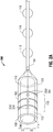
FIG. 1 is an illustration of a sensor sleeve, in accordance with one embodiment of the present disclosure; -
FIG. 2A is an illustration of a sensor sleeve in a closed position, in accordance with a second embodiment of the present disclosure; -
FIGS. 2B is an illustration of the sensor sleeve ofFIG. 2A in an open position, in accordance with the second embodiment of the present disclosure; -
FIGS. 3 is an illustration of a sensor sleeve including optical sensors, in accordance with an embodiment of the present disclosure; -
FIG. 4A is an illustration of a scope for use with the sensor sleeves of the present disclosure; -
FIG. 4B is an illustration of an endobronchial ultrasound (EBUS) bronchoscopy tool for use with the sensor sleeves of the present disclosure; -
FIGS. 5A-5C are sequential operational illustrations of the sensor sleeve ofFIG. 1 in use with the scope ofFIG. 4A at various stages, in accordance with an embodiment of the present disclosure; -
FIG. 6 is an illustration of the sensor sleeve ofFIGS. 2A and2B in use with the EBUS bronchoscopy tool ofFIG. 4B , in accordance with an embodiment of the present disclosure; and -
FIG. 7 illustrates an endobronchial navigation system which may be utilized with the present disclosure. - The present disclosure is directed to devices and systems for providing sensors in parallel with surgical tools. More particularly, the present disclosure is directed to devices for retrofitting various surgical tools, such as bronchoscopes, gastroscopes, endoscopes, and ultrasound scopes (referred to hereinafter as "tools"), with navigational, visualization, and/or other sensors. In addition to the aforementioned tools, those skilled in the art will recognize that the sensors and sensor sleeves described below may also be fitted to other surgical tools, such as laparoscopic tools, thorascoscopic tools, percutaneous tools, etc. Thus, while described below as attached to scopes and other devices with lumens, those skilled in the art will recognize that the sensors and sensor sleeves may also be used with tools without lumens. The sensors may include electromagnetic (EM) sensors, optical, ultrasound, as well as other sensors providing confirmation of location and, where appropriate, further visualization and imaging capabilities for the retrofitted tools. Types of optical sensors may include confocal, near-infrared, Raman spectroscopic, optical coherence tomography, narrow band, etc. Additional examples of types of sensors usable with the present disclosure include metabolic and/or thermal sensors configured to detect positron emission tomography (PET) avid lesions, radiation sensors configured to detect to radionuclides injected into the body to detect where they cluster, as well as pH related sensors and/or protein sensors, among others.
-
FIG. 1 depicts a first embodiment of the present disclosure illustrating aflexible sensor sleeve 100 for enabling the tracking of the location of a tool (FIG. 4A ).Sensor sleeve 100 generally includes atubular body 102 and acabling 104.Tubular body 102 is a hollowed tubular member having alumen 106 extending therethrough defining a central longitudinal axis.Tubular body 102 includes adistal portion 108,proximal portion 110,outer surface 112, andinner surface 114. As illustrated inFIG. 1 , included onouter surface 112 oftubular body 102 are one ormore sensors 116. In other embodiments, one ormore sensors 116 are located betweenouter surface 112 andinner surface 114 within the material forming thetubular body 102. -
Tubular body 102, as illustrated inFIG. 1 , is cylindrical. It is contemplated that forsensor sleeve 100, the diameter oftubular body 102 ranges from about 2mm to about 6mm and is capable of being slideably fitted over similarly sized tools. In some embodiments,sensor sleeve 100 includes a cap (not shown) located atdistal portion 108 which prevents further longitudinal movement of tools once fully inserted intosensor sleeve 100. Alternatively,tubular body 102 may include an area of reduced diameter proximatedistal portion 108 which a tool, once fully inserted, is incapable of moving beyond. In other embodiments, as shown inFIGS. 1 ,5C and6 ,sensor sleeves tubular body 102 and the tool once inserted. - It is contemplated that
sensor sleeve 100 is fabricated from flexible biocompatible materials such as silicone, urethane, thermo plastic elastomer, polyolefins, olefin copolymers, and vinyl polymers.Inner surface 114 may be formed of materials that are sufficiently lubricious that they allow a tool, such asbronchoscope 400 ofFIG. 4A , to be slideably inserted. As will be appreciated by those skilled in the art, a compromise between lubricity and friction fit oftubular body 102 will result in appropriate materials being employed. - The one or
more sensors 116 are, for example, EM sensors, such as those described inU.S. Patent No. 7,233,820 , optical imaging sensors, ultrasound sensors such as piezoelectric polyvinylidenefluoride (PVDF) film, and/or a combination thereof. In some embodiments, one ormore sensors 116 are fabricated ontotubular body 102 ofsensor sleeve 100. In further embodiments, one ormore sensors 116 may be optical shape sensing fibers allowing sensing of shape and/or orientation data along an entire length oftubular body 102. Although illustrated as a plurality of rings ontubular body 102 ofsensor sleeve 100, it is contemplated that one ormore sensors 116 may form other configurations and shapes which provide location information. In the example of utilizing ultrasound sensors, in another embodiment, one ormore sensors 116 are located atdistal portion 108 ofsensor sleeve 100, such that when usingsensor sleeve 100, ultrasound imaging may be undertaken. One ormore sensors 116 may be configured to connect to a workstation, such as workstation 780 (FIG. 7 ), via wired and/or wireless connection. For example, one ormore sensors 116 may be connected toworkstation 780 via one or more wires included incabling 104 and/or via a wireless connection, such as a BLUETOOTH connection. In embodiments, the one ormore sensors 116 may include a printed circuit board with wired and/or wireless communication capability for communicating image data and/or other interrogation or sensed data. The one ormore sensors 116 may further include batteries and/or other wireless power capability. - In the embodiment using EM sensors, once attached to a tool, one or
more sensors 116 creates a six degrees-of-freedom EM tracking system (similar to those disclosed inU.S. Patent No. 6,188,355 and publishedPCT Application Nos. WO 00/10456 WO 01/67035 FIG. 7 . - Cabling 104 is illustrated as coupled to
proximal portion 110 oftubular body 102 and includes one ormore attachments 118. In one embodiment, and as shown inFIG. 1 , one ormore attachments 118 are o-rings, which are configured to slideably receive a body of a tool and frictionally attach the body of the tool tocabling 104. In a further embodiment, and as shown inFIGs. 2A ,2B , and3 , one ormore attachments 118 are adhesive tabs which are configured to adhesively attach cabling 104 to a body of the tool. It is further contemplated that cabling 104 includes, at a proximal end, one or more interface connectors (not shown) configured to be interfaced with a navigation system or an imaging system, such as a ultrasound imaging system, as shown inFIG. 7 . One or more interface connectors may be the in form of a universal serial bus (USB) 3.0, two or three-prong power plug, and/or banana plugs. - Referring now to
FIGS. 2A and2B , an illustration of a second embodiment of a rigid orsemi-rigid sensor sleeve 200 is shown. As further detailed in the description ofFIG. 2B ,sensor sleeve 200 is capable of being opened from a first closed position (FIG. 2A ) to a second open position (FIG. 2B ). As illustrated inFIG. 2A , similar tosensor sleeve 100 ofFIG. 1 ,sensor sleeve 200 has atubular body 102 andcabling 104.Tubular body 102 includes alumen 106 extending therethrough defining a longitudinal axis,distal portion 108,proximal portion 110,outer surface 112, andinner surface 114. Included onouter surface 112 oftubular body 102 are one ormore sensors 116. In other embodiments, one ormore sensors 116 are located betweenouter surface 112 andinner surface 114, depending on the type of sensor utilized. Further, included insensor sleeve 200, onouter surface 112 oftubular body 102, are one ormore snaps 202 and one ormore recesses 204, as illustrated in the closed position inFIG. 2A . Once in a closed position, a connection is formed along axis "B" between one ormore snaps 202 and one or more recesses 204. As further shown inFIG. 2A , axis "B" divides a first portion "I" and a second portion "II" ofsensor sleeve 200 assensor sleeve 200 is transitioned to an open position. - Similar to
FIG. 1 ,tubular body 102, as illustrated inFIG. 2A , is cylindrical. It is contemplated that forsensor sleeve 200, the diameter oftubular body 102 ranges from 2mm to 6mm and is capable of being snap-fitted over similarly sized small tools, and is fabricated from both rigid or semi-rigid and flexible lubricious biocompatible materials such as silicone. - Referring now to
FIG. 2B ,sensor sleeve 200 is illustrated in an open position. As shown inFIG. 2B ,sensor sleeve 200 is capable of being hingedly opened about longitudinally axis "A." Once in the opened position,sensor sleeve 200 is separated into first portion "I" and second portion "II" and each is connected byhinge 206 along axis "A." As shown inFIG. 2B , cabling 104 is attached to first portion "I." It is contemplated that cabling 104 may be attached to either first portion "I" or second portion "II." - One or
more snaps 202 are illustrated as a plurality of tabs and one ofmore recesses 204 are illustrated as recesses which are configured to receive the one or more snaps 202. Each of one ormore recesses 204 and one ormore snaps 202 is shown along edges B and B' of thetubular body 102. Once closed, edges "B" and "B'" have therecesses 204 and snaps 202 mate to secure thetubular body 102 around a tool. Althoughsensor sleeve 200 is illustrated as a rigid or semi-rigid sleeve in a hingedly opened position with one ofmore recesses 204 and one ormore snaps 202 used together to securesensor sleeve 200 in a closed position, in other embodiments a sensor sleeve similar tosensor sleeve 200 does not include one ormore recesses 204 and one ormore snaps 202 and is fabricated from a flexible material which is self-biased, based on the fabricated material, in a closed position, with an opening slit defining edges "B" and "B"'. In this embodiment, a user may open the sensor sleeve, insert a tool, such as those shown inFIGS. 4A and 4B , and allow the elasticity of the material of thesensor sleeve 200 to close around and secure thetubular body 102 to the tool. -
FIG. 3 depicts asensor sleeve 300 similar tosensor sleeve 100, but including optical imaging sensors. Included withintubular body 102 are one or morefiber optic cables 302 and one or moreoptical sensors 304. As illustrated inFIG. 3 , one of morefiber optic cables 302 are located inside oftubular body 102 betweenouter surface 112 andinner surface 114. -
Fiber optic cables 302 are illustrated as fabricated withintubular body 102 and extend throughouttubular body 102 fromproximal portion 110 todistal portion 108.Fiber optic cables 302 are utilized to emit light fromdistal portion 108 ofsensor sleeve 300, which may be reflected and received by one or moreoptical sensors 304. Fiber optic cables extend throughtubular body 102 fromdistal portion 108 throughcabling 104. Alternatively, they may be formed onouter surface 112. It is contemplated thatoptical sensors 304 may be used either alone or in combination with one ormore sensors 116. Such a configuration may be particularly useful with an endobronchial ultrasound (EBUS) scope or a radial endobronchial ultrasound (REBUS) scope enabling not only ultrasound imaging but also EM navigation, as described above, and optical imaging. As shown inFIG. 3 , multiple fiber optic cables are depicted, however only one is necessary and the use of multiple optical sensors may enable greater clarity of and a wider field of view. This may be accomplished by forming composite images based on the combined optical data received by one or moreoptical sensors 304. -
FIGS. 4A and 4B , depict two examples oftools sensor sleeves FIG. 4A illustrates the distal portion of atool 400 utilized to view images inside of a patient's airways.Tool 400 includes abody portion 402, which is inserted into a patient's airways.Body portion 402 includessurface 404 and adistal face 406, which includes animaging lens 408 configured to permit optical viewing of the patient's airways, and a plurality of workingchannels 410. As described herein,sensor sleeves tool 400 or another tool similar in size totool 400. -
FIG. 4B illustrates anEBUS 450 withtransbronchial needle 452 for use during an ultrasound procedure.EBUS 450 includes anultrasound imager 454 at adistal portion 456 ofbody 458. Generally,ultrasound imager 454 allows a clinician to image endobronchial structures with ultrasound. Optionally,EBUS 450 may, in some instances, include aretractable channel 460 through whichretractable transbronchial needle 452 may be inserted. Based on the depicted configuration, it is possible to obtain tissue samples while under ultrasound visualization. Generally,retractable channel 460 is a hollowed tube through whichretractable transbronchial needle 452 can be advanced. In the illustration ofFIG. 4B ,retractable channel 460 andretractable transbronchial needle 452 are each shown in a fully extended position. In the fully retracted position, bothretractable channel 460 andretractable transbronchial needle 452 are located within the interior ofEBUS 450. - Referring now to
FIGS. 5A-5C , illustrations oftool 400 as it is received bysensor sleeve 100 in three stages are shown.FIG. 5A illustratestool 400 prior to insertion intosensor sleeve 100 in direction "D." As shown inFIG. 5A ,tool 400 is located completely outside oflumen 106 ofsensor sleeve 100 withdistal face 406 oftool 400 in alignment withproximal portion 110 of sensor sleeve. In the embodiment shown inFIGS. 5A-5C , one ormore attachments 118 are o-rings, andtool 400 is inserted through each of one ormore attachments 118 prior totool 400 being inserted intosensor sleeve 100. In another embodiment where one ormore attachments 118 are adhesive tabs, during this stage of insertion oftool 400, one ormore attachments 118 are not adhered to surface 404 oftool 400. -
FIG. 5B illustratestool 400 as it is partially inserted intosensor sleeve 100 in direction "D." As shown inFIG. 5B ,sensor sleeve 100 has receiveddistal face 406 oftool 400. Once received, it is contemplated thatinner surface 114 ofsensor sleeve 100 will be in physical contact withsurface 404 oftool 400. Becauseinner surface 114 is generally fabricated from material that is sufficiently lubricious,tool 400 is capable of being slideably received bysensor sleeve 100, while also remaining frictionally engaged. Further,sensor sleeve 100 may be formed of an elastic material allowing it to expand slightly to receivetool 400 and secure thesensor sleeve 100 totool 400. - Referring now to
FIG. 5C ,tool 400 is illustrated as being fully received bysensor sleeve 100. Oncetool 400 is fully inserted intosensor sleeve 100,distal portion 108 ofsensor sleeve 100 is parallel withdistal face 406 oftool 400. As shown inFIG. 5C ,tool 400 is shown as inserted through each of one ormore attachments 118, which are shown as o-rings aroundbody 402 oftool 400. In other embodiments, one ormore attachments 118 are adhesive attachments which are attached to surface 404 oftool 400. It is contemplated that once fully inserted intosensor sleeve 100,tool 400 is frictionally engaged withsensor sleeve 100 such that, following insertion oftool 400 into the airways of a patient and movement therein,sensor sleeve 100 remains engaged withtool 400. -
FIG. 6 , similar toFIG. 5C , depictsEBUS 450 withtransbronchial needle 452 as being fully received bysensor sleeve 200. As shown inFIG. 6 ,retractable transbronchial needle 452 is extended laterally frombody 458 ofEBUS 450. As described in the description ofFIGS. 2A and2B , prior to insertion ofEBUS 400 intosensor sleeve 200,sensor sleeve 200 may be opened by parting one ofmore snaps 202 from one ofmore recesses 204 and inserting EBUS 420 intosensor sleeve 200. OnceEBUS 400 is inserted,sensor sleeve 200 may be closed aroundEBUS 450 by connecting one ormore snaps 202 with one of more recesses 204. Aftersensor sleeve 200 is closed aroundEBUS 450,sensor sleeve 200 may be slideably moved towardsretractable channel 460. Once slideably moved towardsretractable channel 460, one ormore attachments 118 may be adhesively attached to the surface ofbody 458 ofEBUS 400. In other embodiments, one ormore attachments 118 are o-rings which are slideably engaged aroundbody 458 ofEBUS 400. It is contemplated that once fully inserted intosensor sleeve 200,EBUS 450 is frictionally engaged withsensor sleeve 200 such that during movement within and insertion ofEBUS 450 into the airways of a patient,sensor sleeve 200 remains engaged withEBUS 450. Although illustrated usingsensor sleeve 200, as described in the description ofFIG. 4 ,retractable channel 460 andretractable transbronchial needle 452 may be retracted intoEBUS 400 and once retracted intoEBUS 400,EBUS 400 may be received by a sensor sleeve similar tosensor sleeve - With reference now to
FIG. 7 , an EM navigation (EMN)system 710 to be utilized in conjunction with the present disclosure is shown.EMN system 710 generally includes an operating table 740 configured to support a patient; a bronchoscope 750 (such as tool 400) configured for insertion through the patient's mouth and/or nose into the patient's airways;monitoring equipment 760 coupled to bronchoscope 750 for displaying video images received from bronchoscope 750; atracking system 770 including a tracking module 772, a plurality ofreference sensors 774, anEM field generator 776; and aworkstation 780 including software and/or hardware used to facilitate pathway planning, identification of the region of interest, and navigation to the region of interest. - As illustrated in
FIG. 7 , the patient is shown lying on operating table 740 withtool 400 withsensor sleeve 100 attached and inserted through the patient's mouth and into the patient's airways.Tool 400 includes a source of illumination and a video imaging system (not explicitly shown) and is coupled tomonitoring equipment 760, e.g., a video display, for displaying the video images received from the video imaging system oftool 400. As shown inFIG. 7 , sensor sleeve is attached totool 400 with one ormore attachments 118, illustrated as o-rings slideably receivingtool 400. Cabling 104 is illustrated as interfaced withmonitoring equipment 760 and tracking module 772. - As further shown in
FIG. 7 ,EM field generator 776 is positioned beneath the patient.EM field generator 776 and the plurality ofreference sensors 774 are interconnected with tracking module 772, which derives the location of eachreference sensor 774 in six degrees of freedom. Tracking module 772 is configured to track the position of one ormore sensors 116 as it moves in conjunction withtool 400 while within a patient. In accordance with one aspect of the present disclosure, an EM field is generated by anEM field generator 776. The location of one ormore sensors 116 and therefore the location thetool 400 can be determined based on currents induced in the one ormore sensors 116 by the EM field. The induced current is fed to workstation 180 which includesapplication 781 and can convert the detected current to a location mapped to the field generated by the EM field generator. An example of such a tracking system employing an EM field is the SUPERDIMENSION navigation system currently offered by Medtronic PLC. Similarly, one or more ofreference sensors 774, once attached to the chest of the patient, allow the six degrees of freedom coordinates to be sent to workstation 180, which includesapplication 781 where data from one ormore reference sensors 774 is used to calculate a patient coordinate frame of reference. - In another embodiment, the position of one or
more sensors 116 relative to diseased tissue may be determined based on impedance characteristics of tissue surrounding the one ormore sensors 116. Diseased tissue, in any part of the body, will have different characteristics than the surrounding tissue, and thus the distance from which diseased tissue can be identified will vary. For example, depending on the type of disease, diseased tissue may be identified up to 2 centimeters, or even up to 4 centimeters, fromsensors 116. Thus, a diseased area of, for example, the lung may have different impedance characteristics than the surrounding normal tissue such that a sound signal will return at a different frequency from what was transmitted (even without converting it into a picture). This would similarly apply to the spectrum of returning optical wavelengths (visible, infrared, or ultraviolet). The same concepts apply to metabolic, radiation, and other types of sensors. By using such frequency-based interrogation methods, placement of the one or more sensors 116 (and thus tool 400) relative to healthy and diseased tissue at a diagnostic or treatment location may be determined based on the impedance characteristics of the surrounding tissue. - Based on the foregoing disclosures, tools are capable of being retrofitted with a sensor sleeve, which provides independent sensors to be utilized with the tool. Embodiments of the presently disclosed surgical systems and devices are described in detail with reference to the drawings wherein like references numerals identify similar or identical elements. In the drawings, and in the foregoing description, the term "proximal" should be understood as referring to the portion or end of the apparatus, or component thereof, that is closest to a user during proper use, while the term "distal" should be understood as referring to the portion or end of the apparatus, or component thereof, that is furthest from a user during proper use, as is traditional and conventional in the art. These detailed embodiments are merely examples of the disclosure, which may be embodied in various forms. Therefore, specific structural and functional details disclosed herein are not to be interpreted as limiting, but merely as a basis for the claims and as a representative basis for allowing one skilled in the art to variously employ the present disclosure in virtually any appropriately detailed structure.
- The invention may be described by reference to the following numbered paragraphs:-
- 1. A sensor sleeve for use with a tool, the sensor sleeve comprising:
- a tubular body defining a central longitudinal axis and having a lumen defined therethrough, the tubular body being configured to receive a tool;
- a plurality of sensors attached to the tubular body;
- a cabling extending distally from the tubular body; and
- an interface connector coupled to the cabling and configured to interface with a navigation system.
- 2. The sensor sleeve according to paragraph 1, wherein the cabling includes a plurality of attachments configured to secure the cabling to the tool.
- 3. The sensor sleeve according to paragraph 2, wherein the plurality of attachments are o-rings.
- 4. The sensor sleeve according to paragraph 2, wherein the plurality of attachments are adhesive pads.
- 5. The sensor sleeve according to paragraph 1, wherein the lumen has an inner surface fabricated at least partially from a lubricious material.
- 6. The sensor sleeve according to paragraph 1, wherein the tubular body is fabricated at least partially from a flexible biocompatible material.
- 7. The sensor sleeve according to paragraph 1, wherein the tubular body is cylindrical.
- 8. The sensor sleeve according to paragraph 1, wherein the plurality of sensors are selected from the group consisting of electromagnetic (EM) sensors, ultrasound sensors, optical sensors, and piezoelectric polyvinylidenefluoride (PVDF) film.
- 9. The sensor sleeve according to paragraph 1, wherein the tubular body further includes a first shell and a second shell hingedly connected together along a first axis that extends in a direction parallel to the central longitudinal axis.
- 10. The sensor sleeve according to paragraph 9, further including:
- a plurality of snaps attached to the first shell; and
- a plurality of recesses attached to the second shell.
- 11. The sensor sleeve according to paragraph 10, wherein the first shell and second shell are capable of hingedly opening along the first axis.
- 12. The sensor sleeve according to paragraph 10, wherein the tubular body is configured to transition from a first position to a second position.
- 13. The sensor sleeve according to paragraph 12, wherein the first position is open and the second position is closed.
- 14. The sensor sleeve according to paragraph 13, wherein, while in the first position, the first shell and the second shell are semi-cylindrical.
- 15. The sensor sleeve according to paragraph 13, wherein, while in the second position, the first shell and the second shell are connected along a second axis that extends in a direction parallel to the central longitudinal axis and the first axis.
Claims (15)
- A sensor sleeve for use with a tool, the sensor sleeve comprising:a tubular body defining a central longitudinal axis and having a lumen defined therethrough, the tubular body being configured to receive a tool;a plurality of sensors attached to the tubular body;a cabling extending distally from the tubular body; andan interface connector coupled to the cabling and configured to interface with a navigation system.
- The sensor sleeve according to claim 1, wherein the cabling includes a plurality of attachments configured to secure the cabling to the tool.
- The sensor sleeve according to claim 2, wherein the plurality of attachments are o-rings.
- The sensor sleeve according to claim 2, wherein the plurality of attachments are adhesive pads.
- The sensor sleeve according to any preceding claim, wherein the lumen has an inner surface fabricated at least partially from a lubricious material.
- The sensor sleeve according to any preceding claim, wherein the tubular body is fabricated at least partially from a flexible biocompatible material.
- The sensor sleeve according to any preceding claim, wherein the tubular body is cylindrical.
- The sensor sleeve according to any preceding claim, wherein the plurality of sensors are selected from the group consisting of electromagnetic (EM) sensors, ultrasound sensors, optical sensors, and piezoelectric polyvinylidenefluoride (PVDF) film.
- The sensor sleeve according to any preceding claim, wherein the tubular body further includes a first shell and a second shell hingedly connected together along a first axis that extends in a direction parallel to the central longitudinal axis.
- The sensor sleeve according to claim 9, further including:a plurality of snaps attached to the first shell; anda plurality of recesses attached to the second shell.
- The sensor sleeve according to claim 10, wherein the first shell and second shell are capable of hingedly opening along the first axis.
- The sensor sleeve according to claim 10 or claim 11, wherein the tubular body is configured to transition from a first position to a second position.
- The sensor sleeve according to claim 12, wherein the first position is open and the second position is closed.
- The sensor sleeve according to claim 13, wherein, while in the first position, the first shell and the second shell are semi-cylindrical.
- The sensor sleeve according to claim 13 or claim 14, wherein, while in the second position, the first shell and the second shell are connected along a second axis that extends in a direction parallel to the central longitudinal axis and the first axis.
Applications Claiming Priority (2)
| Application Number | Priority Date | Filing Date | Title |
|---|---|---|---|
| US201762579295P | 2017-10-31 | 2017-10-31 | |
| US16/150,340 US11219489B2 (en) | 2017-10-31 | 2018-10-03 | Devices and systems for providing sensors in parallel with medical tools |
Publications (2)
| Publication Number | Publication Date |
|---|---|
| EP3482671A1 true EP3482671A1 (en) | 2019-05-15 |
| EP3482671B1 EP3482671B1 (en) | 2021-05-19 |
Family
ID=64048826
Family Applications (1)
| Application Number | Title | Priority Date | Filing Date |
|---|---|---|---|
| EP18203515.4A Active EP3482671B1 (en) | 2017-10-31 | 2018-10-30 | Sensor sleeve for receiving a tool |
Country Status (3)
| Country | Link |
|---|---|
| US (1) | US11219489B2 (en) |
| EP (1) | EP3482671B1 (en) |
| CN (1) | CN109717955A (en) |
Families Citing this family (4)
| Publication number | Priority date | Publication date | Assignee | Title |
|---|---|---|---|---|
| US20180338673A1 (en) * | 2017-05-26 | 2018-11-29 | Covidien Lp | Surgical sheath and surgical apparatus including the same |
| US11576729B2 (en) * | 2019-06-17 | 2023-02-14 | Koninklijke Philips N.V. | Cranial surgery using optical shape sensing |
| US12295690B2 (en) | 2021-06-15 | 2025-05-13 | Covidien Lp | Systems and methods leveraging audio sensors to facilitate surgical procedures |
| USD1073941S1 (en) * | 2022-01-22 | 2025-05-06 | HJY Forward Medical Investment Co., Ltd. | Disposable integrated endoscope |
Citations (8)
| Publication number | Priority date | Publication date | Assignee | Title |
|---|---|---|---|---|
| FR2541498A1 (en) * | 1980-03-13 | 1984-08-24 | Sarfati Gilbert | Flexible adhesive electric-power cable |
| WO2000010456A1 (en) | 1998-08-02 | 2000-03-02 | Super Dimension Ltd. | Intrabody navigation system for medical applications |
| US6188355B1 (en) | 1997-12-12 | 2001-02-13 | Super Dimension Ltd. | Wireless six-degree-of-freedom locator |
| WO2001067035A1 (en) | 2000-03-09 | 2001-09-13 | Super Dimension Ltd. | Object tracking using a single sensor or a pair of sensors |
| US7233820B2 (en) | 2002-04-17 | 2007-06-19 | Superdimension Ltd. | Endoscope structures and techniques for navigating to a target in branched structure |
| US20130274720A1 (en) * | 2012-04-11 | 2013-10-17 | James K. Brannon | Split endoscopic instrument |
| US20150073217A1 (en) * | 2010-06-04 | 2015-03-12 | Nelson Powell | Intelligent endoscopy systems and methods |
| US20160296105A1 (en) * | 2013-11-18 | 2016-10-13 | Meditech Endoscopy Ltd | Gripping Device |
Family Cites Families (669)
| Publication number | Priority date | Publication date | Assignee | Title |
|---|---|---|---|---|
| US1735726A (en) | 1929-11-12 | bornhardt | ||
| US1576781A (en) | 1924-04-22 | 1926-03-16 | Herman B Philips | Fluoroscopic fracture apparatus |
| US2407845A (en) | 1943-01-16 | 1946-09-17 | California Inst Res Found | Aligning device for tools |
| US2650588A (en) | 1950-12-29 | 1953-09-01 | Drew Harry Guy Radcliffe | Artificial femoral head having an x-ray marker |
| US2697433A (en) | 1951-12-04 | 1954-12-21 | Max A Zehnder | Device for accurately positioning and guiding guide wires used in the nailing of thefemoral neck |
| US3073310A (en) | 1957-08-05 | 1963-01-15 | Zenon R Mocarski | Surgical instrument positioning device |
| US3016899A (en) | 1958-11-03 | 1962-01-16 | Carl B Stenvall | Surgical instrument |
| NL107206C (en) | 1959-03-07 | 1900-01-01 | ||
| US3017887A (en) | 1960-01-19 | 1962-01-23 | William T Heyer | Stereotaxy device |
| US3109588A (en) | 1962-01-26 | 1963-11-05 | William L Polhemus | Celestial computers |
| US3294083A (en) | 1963-08-26 | 1966-12-27 | Alderson Res Lab Inc | Dosimetry system for penetrating radiation |
| US3367326A (en) | 1965-06-15 | 1968-02-06 | Calvin H. Frazier | Intra spinal fixation rod |
| DE1238814B (en) | 1966-02-23 | 1967-04-13 | Merckle Flugzeugwerke G M B H | Inductive angle encoder based on the transformer principle |
| US3577160A (en) | 1968-01-10 | 1971-05-04 | James E White | X-ray gauging apparatus with x-ray opaque markers in the x-ray path to indicate alignment of x-ray tube, subject and film |
| GB1257034A (en) | 1968-03-25 | 1971-12-15 | ||
| SE336642B (en) | 1969-10-28 | 1971-07-12 | Astra Meditec Ab | |
| US3644825A (en) | 1969-12-31 | 1972-02-22 | Texas Instruments Inc | Magnetic detection system for detecting movement of an object utilizing signals derived from two orthogonal pickup coils |
| US3704707A (en) | 1971-04-06 | 1972-12-05 | William X Halloran | Orthopedic drill guide apparatus |
| US3702935A (en) | 1971-10-13 | 1972-11-14 | Litton Medical Products | Mobile fluoroscopic unit for bedside catheter placement |
| US3821469A (en) | 1972-05-15 | 1974-06-28 | Amperex Electronic Corp | Graphical data device |
| US4017858A (en) | 1973-07-30 | 1977-04-12 | Polhemus Navigation Sciences, Inc. | Apparatus for generating a nutating electromagnetic field |
| US3868565A (en) | 1973-07-30 | 1975-02-25 | Jack Kuipers | Object tracking and orientation determination means, system and process |
| US3941127A (en) | 1974-10-03 | 1976-03-02 | Froning Edward C | Apparatus and method for stereotaxic lateral extradural disc puncture |
| US3983474A (en) | 1975-02-21 | 1976-09-28 | Polhemus Navigation Sciences, Inc. | Tracking and determining orientation of object using coordinate transformation means, system and process |
| US4052620A (en) | 1975-11-28 | 1977-10-04 | Picker Corporation | Method and apparatus for improved radiation detection in radiation scanning systems |
| US4054881A (en) | 1976-04-26 | 1977-10-18 | The Austin Company | Remote object position locater |
| US4037592A (en) | 1976-05-04 | 1977-07-26 | Kronner Richard F | Guide pin locating tool and method |
| US5291199A (en) | 1977-01-06 | 1994-03-01 | Westinghouse Electric Corp. | Threat signal detection system |
| US4298874A (en) | 1977-01-17 | 1981-11-03 | The Austin Company | Method and apparatus for tracking objects |
| DE2718804C3 (en) | 1977-04-27 | 1979-10-31 | Karlheinz Prof. Dr. 3000 Hannover Renner | Device for positioning control of patients and / or radiation sources |
| US4173228A (en) | 1977-05-16 | 1979-11-06 | Applied Medical Devices | Catheter locating device |
| US4182312A (en) | 1977-05-20 | 1980-01-08 | Mushabac David R | Dental probe |
| SU745505A1 (en) | 1977-09-28 | 1980-07-05 | Научно-Исследовательский Институт Экспериментальной Медицины Амн Ссср | Method of guiding stereotaxic tool on target point |
| US4117337A (en) | 1977-11-03 | 1978-09-26 | General Electric Company | Patient positioning indication arrangement for a computed tomography system |
| DE7805301U1 (en) | 1978-02-22 | 1978-07-06 | Howmedica International, Inc. Zweigniederlassung Kiel, 2300 Kiel | Distal aiming device for locking nailing |
| US4202349A (en) | 1978-04-24 | 1980-05-13 | Jones James W | Radiopaque vessel markers |
| USRE32619E (en) | 1978-11-20 | 1988-03-08 | Apparatus and method for nuclear magnetic resonance scanning and mapping | |
| US4256112A (en) | 1979-02-12 | 1981-03-17 | David Kopf Instruments | Head positioner |
| US4341220A (en) | 1979-04-13 | 1982-07-27 | Pfizer Inc. | Stereotactic surgery apparatus and method |
| FR2458838A1 (en) | 1979-06-06 | 1981-01-02 | Thomson Csf | DEVICE FOR MEASURING THE RELATIVE ORIENTATION OF TWO BODIES AND CORRESPONDING STEERING SYSTEM |
| US4314251A (en) | 1979-07-30 | 1982-02-02 | The Austin Company | Remote object position and orientation locater |
| US4287809A (en) | 1979-08-20 | 1981-09-08 | Honeywell Inc. | Helmet-mounted sighting system |
| US4608977A (en) | 1979-08-29 | 1986-09-02 | Brown Russell A | System using computed tomography as for selective body treatment |
| US4419012A (en) | 1979-09-11 | 1983-12-06 | Elliott Brothers (London) Limited | Position measuring system |
| US4317078A (en) | 1979-10-15 | 1982-02-23 | Ohio State University Research Foundation | Remote position and orientation detection employing magnetic flux linkage |
| US4319136A (en) | 1979-11-09 | 1982-03-09 | Jinkins J Randolph | Computerized tomography radiograph data transfer cap |
| DE2950819A1 (en) | 1979-12-17 | 1981-06-25 | Siemens AG, 1000 Berlin und 8000 München | RADIATION DIAGNOSTICS DEVICE FOR THE PRODUCTION OF LAYER IMAGES |
| US4346384A (en) | 1980-06-30 | 1982-08-24 | The Austin Company | Remote object position and orientation locator |
| US4328548A (en) | 1980-04-04 | 1982-05-04 | The Austin Company | Locator for source of electromagnetic radiation having unknown structure or orientation |
| EP0039206B1 (en) | 1980-04-23 | 1984-10-10 | Inoue-Japax Research Incorporated | Magnetic treatment device |
| US4688037A (en) | 1980-08-18 | 1987-08-18 | Mcdonnell Douglas Corporation | Electromagnetic communications and switching system |
| US4339953A (en) | 1980-08-29 | 1982-07-20 | Aisin Seiki Company, Ltd. | Position sensor |
| US4638798A (en) | 1980-09-10 | 1987-01-27 | Shelden C Hunter | Stereotactic method and apparatus for locating and treating or removing lesions |
| US4328813A (en) | 1980-10-20 | 1982-05-11 | Medtronic, Inc. | Brain lead anchoring system |
| US4358856A (en) | 1980-10-31 | 1982-11-09 | General Electric Company | Multiaxial x-ray apparatus |
| DE3042343A1 (en) | 1980-11-10 | 1982-06-09 | Philips Patentverwaltung Gmbh, 2000 Hamburg | Synthetic formation of defect-free images - by superimposed blurring images of defect on reconstituted multiple perspective images |
| AU7986682A (en) | 1981-02-12 | 1982-08-19 | New York University | Apparatus for stereotactic surgery |
| NL8101722A (en) | 1981-04-08 | 1982-11-01 | Philips Nv | CONTOUR METER. |
| US4710708A (en) | 1981-04-27 | 1987-12-01 | Develco | Method and apparatus employing received independent magnetic field components of a transmitted alternating magnetic field for determining location |
| US4431005A (en) | 1981-05-07 | 1984-02-14 | Mccormick Laboratories, Inc. | Method of and apparatus for determining very accurately the position of a device inside biological tissue |
| FI64282C (en) | 1981-06-04 | 1983-11-10 | Instrumentarium Oy | DIAGNOSISPARATUR FOER BESTAEMMANDE AV VAEVNADERNAS STRUKTUR OC SAMMANSAETTNING |
| US4422041A (en) | 1981-07-30 | 1983-12-20 | The United States Of America As Represented By The Secretary Of The Army | Magnet position sensing system |
| US4396945A (en) | 1981-08-19 | 1983-08-02 | Solid Photography Inc. | Method of sensing the position and orientation of elements in space |
| US4645343A (en) | 1981-11-11 | 1987-02-24 | U.S. Philips Corporation | Atomic resonance line source lamps and spectrophotometers for use with such lamps |
| US4485815A (en) | 1982-08-30 | 1984-12-04 | Kurt Amplatz | Device and method for fluoroscope-monitored percutaneous puncture treatment |
| US4506676A (en) | 1982-09-10 | 1985-03-26 | Duska Alois A | Radiographic localization technique |
| US4447224A (en) | 1982-09-20 | 1984-05-08 | Infusaid Corporation | Variable flow implantable infusion apparatus |
| US4584577A (en) | 1982-10-20 | 1986-04-22 | Brookes & Gatehouse Limited | Angular position sensor |
| US4961422A (en) | 1983-01-21 | 1990-10-09 | Marchosky J Alexander | Method and apparatus for volumetric interstitial conductive hyperthermia |
| US4651732A (en) | 1983-03-17 | 1987-03-24 | Frederick Philip R | Three-dimensional light guidance system for invasive procedures |
| NL8300965A (en) | 1983-03-17 | 1984-10-16 | Nicolaas Roelof Snijder | SYSTEM FOR EXAMINATION OF SKELETON PARTS OF THE BODY OF A LIVING ORIGIN, IN PARTICULAR THE SPIRIT OF THE HUMAN BODY. |
| US4613866A (en) | 1983-05-13 | 1986-09-23 | Mcdonnell Douglas Corporation | Three dimensional digitizer with electromagnetic coupling |
| NL8302228A (en) | 1983-06-22 | 1985-01-16 | Optische Ind De Oude Delft Nv | MEASURING SYSTEM FOR USING A TRIANGULAR PRINCIPLE, CONTACT-FREE MEASURING A DISTANCE GIVEN BY A SURFACE CONTOUR TO AN OBJECTIVE LEVEL. |
| DE3332642A1 (en) | 1983-09-09 | 1985-04-04 | Ortopedia Gmbh, 2300 Kiel | DEVICE FOR DETECTING CROSS HOLES INTRAMEDULLA IMPLANTS |
| US4618978A (en) | 1983-10-21 | 1986-10-21 | Cosman Eric R | Means for localizing target coordinates in a body relative to a guidance system reference frame in any arbitrary plane as viewed by a tomographic image through the body |
| SE8306243L (en) | 1983-11-14 | 1985-05-15 | Cytex Medicinteknik Ab | LOCATION METHODOLOGY |
| DE3342675A1 (en) | 1983-11-25 | 1985-06-05 | Fa. Carl Zeiss, 7920 Heidenheim | METHOD AND DEVICE FOR CONTACTLESS MEASUREMENT OF OBJECTS |
| US4753528A (en) | 1983-12-13 | 1988-06-28 | Quantime, Inc. | Laser archery distance device |
| US4549555A (en) | 1984-02-17 | 1985-10-29 | Orthothronics Limited Partnership | Knee laxity evaluator and motion module/digitizer arrangement |
| US4841967A (en) | 1984-01-30 | 1989-06-27 | Chang Ming Z | Positioning device for percutaneous needle insertion |
| US4571834A (en) | 1984-02-17 | 1986-02-25 | Orthotronics Limited Partnership | Knee laxity evaluator and motion module/digitizer arrangement |
| US4583538A (en) | 1984-05-04 | 1986-04-22 | Onik Gary M | Method and apparatus for stereotaxic placement of probes in the body utilizing CT scanner localization |
| US4649504A (en) | 1984-05-22 | 1987-03-10 | Cae Electronics, Ltd. | Optical position and orientation measurement techniques |
| US4642786A (en) | 1984-05-25 | 1987-02-10 | Position Orientation Systems, Ltd. | Method and apparatus for position and orientation measurement using a magnetic field and retransmission |
| DE8417428U1 (en) | 1984-06-08 | 1984-09-13 | Howmedica International, Inc. Zweigniederlassung Kiel, 2300 Kiel | Target device |
| US4572198A (en) | 1984-06-18 | 1986-02-25 | Varian Associates, Inc. | Catheter for use with NMR imaging systems |
| US4548208A (en) | 1984-06-27 | 1985-10-22 | Medtronic, Inc. | Automatic adjusting induction coil treatment device |
| JPS6149205A (en) | 1984-08-16 | 1986-03-11 | Seiko Instr & Electronics Ltd | Robot control system |
| US4889526A (en) | 1984-08-27 | 1989-12-26 | Magtech Laboratories, Inc. | Non-invasive method and apparatus for modulating brain signals through an external magnetic or electric field to reduce pain |
| US4617925A (en) | 1984-10-01 | 1986-10-21 | Laitinen Lauri V | Adapter for definition of the position of brain structures |
| US4705395A (en) | 1984-10-03 | 1987-11-10 | Diffracto Ltd. | Triangulation data integrity |
| US4821206A (en) | 1984-11-27 | 1989-04-11 | Photo Acoustic Technology, Inc. | Ultrasonic apparatus for positioning a robot hand |
| US4706665A (en) | 1984-12-17 | 1987-11-17 | Gouda Kasim I | Frame for stereotactic surgery |
| DE3500605A1 (en) | 1985-01-10 | 1986-07-10 | Markus Dr. 5300 Bonn Hansen | DEVICE FOR MEASURING THE POSITIONS AND MOVEMENTS OF THE LOWER JAW RELATIVE TO THE UPPER JAW |
| US4722336A (en) | 1985-01-25 | 1988-02-02 | Michael Kim | Placement guide |
| DE3508730A1 (en) | 1985-03-12 | 1986-09-18 | Siemens AG, 1000 Berlin und 8000 München | Measuring device for medical purposes |
| US4782239A (en) | 1985-04-05 | 1988-11-01 | Nippon Kogaku K. K. | Optical position measuring apparatus |
| CH671873A5 (en) | 1985-10-03 | 1989-10-13 | Synthes Ag | |
| US4838265A (en) | 1985-05-24 | 1989-06-13 | Cosman Eric R | Localization device for probe placement under CT scanner imaging |
| US4737921A (en) | 1985-06-03 | 1988-04-12 | Dynamic Digital Displays, Inc. | Three dimensional medical image display system |
| DE3520782A1 (en) | 1985-06-10 | 1986-12-11 | Siemens AG, 1000 Berlin und 8000 München | Medicament metering device with reservoir and metering store |
| SE447848B (en) | 1985-06-14 | 1986-12-15 | Anders Bengtsson | INSTRUMENTS FOR SEATING SURFACE TOPOGRAPHY |
| US4743771A (en) | 1985-06-17 | 1988-05-10 | View Engineering, Inc. | Z-axis height measurement system |
| US4805615A (en) | 1985-07-02 | 1989-02-21 | Carol Mark P | Method and apparatus for performing stereotactic surgery |
| US4653509A (en) | 1985-07-03 | 1987-03-31 | The United States Of America As Represented By The Secretary Of The Air Force | Guided trephine samples for skeletal bone studies |
| US4719419A (en) | 1985-07-15 | 1988-01-12 | Harris Graphics Corporation | Apparatus for detecting a rotary position of a shaft |
| US4737032A (en) | 1985-08-26 | 1988-04-12 | Cyberware Laboratory, Inc. | Surface mensuration sensor |
| US4705401A (en) | 1985-08-12 | 1987-11-10 | Cyberware Laboratory Inc. | Rapid three-dimensional surface digitizer |
| IL76517A (en) | 1985-09-27 | 1989-02-28 | Nessim Igal Levy | Distance measuring device |
| US4709156A (en) | 1985-11-27 | 1987-11-24 | Ex-Cell-O Corporation | Method and apparatus for inspecting a surface |
| US4794262A (en) | 1985-12-03 | 1988-12-27 | Yukio Sato | Method and apparatus for measuring profile of three-dimensional object |
| US4737794A (en) | 1985-12-09 | 1988-04-12 | Mcdonnell Douglas Corporation | Method and apparatus for determining remote object orientation and position |
| US4742356A (en) | 1985-12-09 | 1988-05-03 | Mcdonnell Douglas Corporation | Method and apparatus for determining remote object orientation and position |
| DE3543867C3 (en) | 1985-12-12 | 1994-10-06 | Wolf Gmbh Richard | Device for the spatial location and destruction of concrements in body cavities |
| US4742815A (en) | 1986-01-02 | 1988-05-10 | Ninan Champil A | Computer monitoring of endoscope |
| US4722056A (en) | 1986-02-18 | 1988-01-26 | Trustees Of Dartmouth College | Reference display systems for superimposing a tomagraphic image onto the focal plane of an operating microscope |
| JP2685071B2 (en) | 1986-03-10 | 1997-12-03 | 三菱電機株式会社 | Numerical control unit |
| SE469321B (en) | 1986-04-14 | 1993-06-21 | Joenkoepings Laens Landsting | SET AND DEVICE TO MAKE A MODIFIED THREE-DIMENSIONAL IMAGE OF AN ELASTIC DEFORMABLE PURPOSE |
| US4821731A (en) | 1986-04-25 | 1989-04-18 | Intra-Sonix, Inc. | Acoustic image system and method |
| US4862893A (en) | 1987-12-08 | 1989-09-05 | Intra-Sonix, Inc. | Ultrasonic transducer |
| US5002058A (en) | 1986-04-25 | 1991-03-26 | Intra-Sonix, Inc. | Ultrasonic transducer |
| US4977655A (en) | 1986-04-25 | 1990-12-18 | Intra-Sonix, Inc. | Method of making a transducer |
| US5078140A (en) | 1986-05-08 | 1992-01-07 | Kwoh Yik S | Imaging device - aided robotic stereotaxis system |
| US4822163A (en) | 1986-06-26 | 1989-04-18 | Robotic Vision Systems, Inc. | Tracking vision sensor |
| US4723544A (en) | 1986-07-09 | 1988-02-09 | Moore Robert R | Hemispherical vectoring needle guide for discolysis |
| US4791934A (en) | 1986-08-07 | 1988-12-20 | Picker International, Inc. | Computer tomography assisted stereotactic surgery system and method |
| US4733969A (en) | 1986-09-08 | 1988-03-29 | Cyberoptics Corporation | Laser probe for determining distance |
| US4743770A (en) | 1986-09-22 | 1988-05-10 | Mitutoyo Mfg. Co., Ltd. | Profile-measuring light probe using a change in reflection factor in the proximity of a critical angle of light |
| US4761072A (en) | 1986-09-30 | 1988-08-02 | Diffracto Ltd. | Electro-optical sensors for manual control |
| US4849692A (en) | 1986-10-09 | 1989-07-18 | Ascension Technology Corporation | Device for quantitatively measuring the relative position and orientation of two bodies in the presence of metals utilizing direct current magnetic fields |
| US4945305A (en) | 1986-10-09 | 1990-07-31 | Ascension Technology Corporation | Device for quantitatively measuring the relative position and orientation of two bodies in the presence of metals utilizing direct current magnetic fields |
| US4750487A (en) | 1986-11-24 | 1988-06-14 | Zanetti Paul H | Stereotactic frame |
| DE3703422A1 (en) | 1987-02-05 | 1988-08-18 | Zeiss Carl Fa | OPTOELECTRONIC DISTANCE SENSOR |
| US4745290A (en) | 1987-03-19 | 1988-05-17 | David Frankel | Method and apparatus for use in making custom shoes |
| US4804261A (en) | 1987-03-27 | 1989-02-14 | Kirschen David G | Anti-claustrophobic glasses |
| JPH0685784B2 (en) | 1987-03-30 | 1994-11-02 | 株式会社東芝 | Surgical three-dimensional viewer system |
| US4875478A (en) | 1987-04-10 | 1989-10-24 | Chen Harry H | Portable compression grid & needle holder |
| US4793355A (en) | 1987-04-17 | 1988-12-27 | Biomagnetic Technologies, Inc. | Apparatus for process for making biomagnetic measurements |
| US4809694A (en) | 1987-05-19 | 1989-03-07 | Ferrara Vincent L | Biopsy guide |
| DE3717871C3 (en) | 1987-05-27 | 1995-05-04 | Georg Prof Dr Schloendorff | Method and device for reproducible visual representation of a surgical intervention |
| US4836778A (en) | 1987-05-26 | 1989-06-06 | Vexcel Corporation | Mandibular motion monitoring system |
| JPH02503519A (en) | 1987-05-27 | 1990-10-25 | サージカル ナビゲーション テクノロジース インコーポレーティッド(アン アフィリエイティッド カンパニー オブ ソファマー ダンネク グループ インコーポレーティッド) | Method and apparatus for reproducibly optically displaying surgical procedures |
| US4845771A (en) | 1987-06-29 | 1989-07-04 | Picker International, Inc. | Exposure monitoring in radiation imaging |
| US4989608A (en) | 1987-07-02 | 1991-02-05 | Ratner Adam V | Device construction and method facilitating magnetic resonance imaging of foreign objects in a body |
| FR2618211B1 (en) | 1987-07-15 | 1991-11-15 | Chardon Bernard | FRONTAL LIGHTING DEVICE FOR OBSERVING NARROW AND DEEP CAVITIES. |
| US4829373A (en) | 1987-08-03 | 1989-05-09 | Vexcel Corporation | Stereo mensuration apparatus |
| US4769005A (en) | 1987-08-06 | 1988-09-06 | Robert Ginsburg | Selective catheter guide |
| US4797907A (en) | 1987-08-07 | 1989-01-10 | Diasonics Inc. | Battery enhanced power generation for mobile X-ray machine |
| US4931056A (en) | 1987-09-04 | 1990-06-05 | Neurodynamics, Inc. | Catheter guide apparatus for perpendicular insertion into a cranium orifice |
| JPS6472736A (en) | 1987-09-14 | 1989-03-17 | Toshiba Corp | Mri apparatus |
| US4991579A (en) | 1987-11-10 | 1991-02-12 | Allen George S | Method and apparatus for providing related images over time of a portion of the anatomy using fiducial implants |
| US5079699A (en) | 1987-11-27 | 1992-01-07 | Picker International, Inc. | Quick three-dimensional display |
| US4875165A (en) | 1987-11-27 | 1989-10-17 | University Of Chicago | Method for determination of 3-D structure in biplane angiography |
| US5027818A (en) | 1987-12-03 | 1991-07-02 | University Of Florida | Dosimetric technique for stereotactic radiosurgery same |
| US4869255A (en) | 1987-12-04 | 1989-09-26 | Ad-Tech Medical Instrument Corp. | Electrical connection device |
| EP0326768A3 (en) | 1988-02-01 | 1991-01-23 | Faro Medical Technologies Inc. | Computer-aided surgery apparatus |
| US5251127A (en) | 1988-02-01 | 1993-10-05 | Faro Medical Technologies Inc. | Computer-aided surgery apparatus |
| US4951653A (en) | 1988-03-02 | 1990-08-28 | Laboratory Equipment, Corp. | Ultrasound brain lesioning system |
| US4869247A (en) | 1988-03-11 | 1989-09-26 | The University Of Virginia Alumni Patents Foundation | Video tumor fighting system |
| US4884566A (en) | 1988-04-15 | 1989-12-05 | The University Of Michigan | System and method for determining orientation of planes of imaging |
| NL8801750A (en) | 1988-07-11 | 1990-02-01 | Philips Nv | ROENTGEN RESEARCH DEVICE WITH A BALANCED TRIPOD. |
| US5050608A (en) | 1988-07-12 | 1991-09-24 | Medirand, Inc. | System for indicating a position to be operated in a patient's body |
| US4896673A (en) | 1988-07-15 | 1990-01-30 | Medstone International, Inc. | Method and apparatus for stone localization using ultrasound imaging |
| US4860331A (en) | 1988-09-12 | 1989-08-22 | Williams John F | Image marker device |
| US4905698A (en) | 1988-09-13 | 1990-03-06 | Pharmacia Deltec Inc. | Method and apparatus for catheter location determination |
| US5265611A (en) | 1988-09-23 | 1993-11-30 | Siemens Aktiengellschaft | Apparatus for measuring weak, location-dependent and time-dependent magnetic field |
| EP0359864B1 (en) | 1988-09-23 | 1993-12-01 | Siemens Aktiengesellschaft | Apparatus and method for the measurement of weak magnetic fields dependent upon position and time |
| IT1227365B (en) | 1988-11-18 | 1991-04-08 | Istituto Neurologico Carlo Bes | PROCEDURE AND EQUIPMENT PARTICULARLY FOR THE GUIDE OF NEUROSURGICAL OPERATIONS |
| US5099846A (en) | 1988-12-23 | 1992-03-31 | Hardy Tyrone L | Method and apparatus for video presentation from a variety of scanner imaging sources |
| US5143076A (en) | 1988-12-23 | 1992-09-01 | Tyrone L. Hardy | Three-dimensional beam localization microscope apparatus for stereotactic diagnoses or surgery |
| US5098426A (en) | 1989-02-06 | 1992-03-24 | Phoenix Laser Systems, Inc. | Method and apparatus for precision laser surgery |
| US5197476A (en) | 1989-03-16 | 1993-03-30 | Christopher Nowacki | Locating target in human body |
| CN1049287A (en) | 1989-05-24 | 1991-02-20 | 住友电气工业株式会社 | The treatment conduit |
| US5024226A (en) | 1989-08-17 | 1991-06-18 | Critikon, Inc. | Epidural oxygen sensor |
| US5285787A (en) | 1989-09-12 | 1994-02-15 | Kabushiki Kaisha Toshiba | Apparatus for calculating coordinate data of desired point in subject to be examined |
| GB8920697D0 (en) | 1989-09-13 | 1989-10-25 | Isis Innovation | Apparatus and method for aligning drilling apparatus in surgical procedures |
| US5257998A (en) | 1989-09-20 | 1993-11-02 | Mitaka Kohki Co., Ltd. | Medical three-dimensional locating apparatus |
| US5681260A (en) | 1989-09-22 | 1997-10-28 | Olympus Optical Co., Ltd. | Guiding apparatus for guiding an insertable body within an inspected object |
| IL91805A (en) | 1989-09-27 | 1996-12-05 | Elscint Ltd | Quadrature surface coil |
| EP0419729A1 (en) | 1989-09-29 | 1991-04-03 | Siemens Aktiengesellschaft | Position finding of a catheter by means of non-ionising fields |
| FR2652928B1 (en) | 1989-10-05 | 1994-07-29 | Diadix Sa | INTERACTIVE LOCAL INTERVENTION SYSTEM WITHIN A AREA OF A NON-HOMOGENEOUS STRUCTURE. |
| US5005592A (en) | 1989-10-27 | 1991-04-09 | Becton Dickinson And Company | Method and apparatus for tracking catheters |
| ES2085885T3 (en) | 1989-11-08 | 1996-06-16 | George S Allen | MECHANICAL ARM FOR INTERACTIVE SURGERY SYSTEM DIRECTED BY IMAGES. |
| US5222499A (en) | 1989-11-15 | 1993-06-29 | Allen George S | Method and apparatus for imaging the anatomy |
| US5190059A (en) | 1989-11-16 | 1993-03-02 | Fabian Carl E | Surgical implement detector utilizing a powered marker |
| US5057095A (en) | 1989-11-16 | 1991-10-15 | Fabian Carl E | Surgical implement detector utilizing a resonant marker |
| US5329944A (en) | 1989-11-16 | 1994-07-19 | Fabian Carl E | Surgical implement detector utilizing an acoustic marker |
| US5107862A (en) | 1991-05-06 | 1992-04-28 | Fabian Carl E | Surgical implement detector utilizing a powered marker |
| US5188126A (en) | 1989-11-16 | 1993-02-23 | Fabian Carl E | Surgical implement detector utilizing capacitive coupling |
| US5105829A (en) | 1989-11-16 | 1992-04-21 | Fabian Carl E | Surgical implement detector utilizing capacitive coupling |
| US5047036A (en) | 1989-11-17 | 1991-09-10 | Koutrouvelis Panos G | Stereotactic device |
| US5308352A (en) | 1989-11-17 | 1994-05-03 | Koutrouvelis Panos G | Stereotactic device |
| CA2003497C (en) | 1989-11-21 | 1999-04-06 | Michael M. Greenberg | Probe-correlated viewing of anatomical image data |
| EP0502069A1 (en) | 1989-11-24 | 1992-09-09 | Technomed International | A method and apparatus for determining the position of a target relative to known co-ordinates |
| FR2655415B1 (en) | 1989-12-01 | 1992-02-21 | Sextant Avionique | ELECTROMAGNETIC POSITION AND ORIENTATION DETECTOR. |
| US5013317A (en) | 1990-02-07 | 1991-05-07 | Smith & Nephew Richards Inc. | Medical drill assembly transparent to X-rays and targeting drill bit |
| US5031203A (en) | 1990-02-09 | 1991-07-09 | Trecha Randal R | Coaxial laser targeting device for use with x-ray equipment and surgical drill equipment during surgical procedures |
| US5214615A (en) | 1990-02-26 | 1993-05-25 | Will Bauer | Three-dimensional displacement of a body with computer interface |
| JP2653210B2 (en) | 1990-03-16 | 1997-09-17 | 天美 加藤 | Stereotactic brain surgery support device |
| FI89132C (en) | 1990-04-06 | 1993-08-25 | Orion Yhtymae Oy | Method for fine-needle biopsy or for performing a tissue marker in conjunction with mammography and arrangements for performing the procedure |
| US5224049A (en) | 1990-04-10 | 1993-06-29 | Mushabac David R | Method, system and mold assembly for use in preparing a dental prosthesis |
| US5253647A (en) | 1990-04-13 | 1993-10-19 | Olympus Optical Co., Ltd. | Insertion position and orientation state pickup for endoscope |
| JP2750201B2 (en) | 1990-04-13 | 1998-05-13 | オリンパス光学工業株式会社 | Endoscope insertion state detection device |
| US5107839A (en) | 1990-05-04 | 1992-04-28 | Pavel V. Houdek | Computer controlled stereotaxic radiotherapy system and method |
| US5030222A (en) | 1990-05-09 | 1991-07-09 | James Calandruccio | Radiolucent orthopedic chuck |
| US5086401A (en) | 1990-05-11 | 1992-02-04 | International Business Machines Corporation | Image-directed robotic system for precise robotic surgery including redundant consistency checking |
| US5295483A (en) | 1990-05-11 | 1994-03-22 | Christopher Nowacki | Locating target in human body |
| US5457641A (en) | 1990-06-29 | 1995-10-10 | Sextant Avionique | Method and apparatus for determining an orientation associated with a mobile system, especially a line of sight inside a helmet visor |
| US5017139A (en) | 1990-07-05 | 1991-05-21 | Mushabac David R | Mechanical support for hand-held dental/medical instrument |
| GB9018660D0 (en) | 1990-08-24 | 1990-10-10 | Imperial College | Probe system |
| US5193106A (en) | 1990-08-28 | 1993-03-09 | Desena Danforth | X-ray identification marker |
| US5160337A (en) | 1990-09-24 | 1992-11-03 | Cosman Eric R | Curved-shaped floor stand for use with a linear accelerator in radiosurgery |
| US5198877A (en) | 1990-10-15 | 1993-03-30 | Pixsys, Inc. | Method and apparatus for three-dimensional non-contact shape sensing |
| US6347240B1 (en) | 1990-10-19 | 2002-02-12 | St. Louis University | System and method for use in displaying images of a body part |
| EP0553246B1 (en) | 1990-10-19 | 2000-09-13 | St. Louis University | Surgical probe locating system for head use |
| US5059789A (en) | 1990-10-22 | 1991-10-22 | International Business Machines Corp. | Optical position and orientation sensor |
| FR2668359B1 (en) | 1990-10-24 | 1998-02-20 | Gen Electric Cgr | MAMMOGRAPH PROVIDED WITH A PERFECTED NEEDLE HOLDER. |
| US5823958A (en) | 1990-11-26 | 1998-10-20 | Truppe; Michael | System and method for displaying a structural data image in real-time correlation with moveable body |
| JP2715762B2 (en) | 1990-11-30 | 1998-02-18 | 富士写真光機株式会社 | Ultrasonic inspection equipment |
| US5054492A (en) | 1990-12-17 | 1991-10-08 | Cardiovascular Imaging Systems, Inc. | Ultrasonic imaging catheter having rotational image correlation |
| US5947981A (en) | 1995-01-31 | 1999-09-07 | Cosman; Eric R. | Head and neck localizer |
| US5662111A (en) | 1991-01-28 | 1997-09-02 | Cosman; Eric R. | Process of stereotactic optical navigation |
| US6006126A (en) | 1991-01-28 | 1999-12-21 | Cosman; Eric R. | System and method for stereotactic registration of image scan data |
| US6405072B1 (en) | 1991-01-28 | 2002-06-11 | Sherwood Services Ag | Apparatus and method for determining a location of an anatomical target with reference to a medical apparatus |
| US5480439A (en) | 1991-02-13 | 1996-01-02 | Lunar Corporation | Method for periprosthetic bone mineral density measurement |
| US5228442A (en) | 1991-02-15 | 1993-07-20 | Cardiac Pathways Corporation | Method for mapping, ablation, and stimulation using an endocardial catheter |
| US5161536A (en) | 1991-03-22 | 1992-11-10 | Catheter Technology | Ultrasonic position indicating apparatus and methods |
| US5257636A (en) | 1991-04-02 | 1993-11-02 | Steven J. White | Apparatus for determining position of an endothracheal tube |
| US5339799A (en) | 1991-04-23 | 1994-08-23 | Olympus Optical Co., Ltd. | Medical system for reproducing a state of contact of the treatment section in the operation unit |
| US5291889A (en) | 1991-05-23 | 1994-03-08 | Vanguard Imaging Ltd. | Apparatus and method for spatially positioning images |
| FI93607C (en) | 1991-05-24 | 1995-05-10 | John Koivukangas | Cutting Remedy |
| US5187475A (en) | 1991-06-10 | 1993-02-16 | Honeywell Inc. | Apparatus for determining the position of an object |
| US5417210A (en) | 1992-05-27 | 1995-05-23 | International Business Machines Corporation | System and method for augmentation of endoscopic surgery |
| US5279309A (en) | 1991-06-13 | 1994-01-18 | International Business Machines Corporation | Signaling device and method for monitoring positions in a surgical operation |
| DE9107298U1 (en) | 1991-06-13 | 1991-07-25 | Howmedica GmbH, 2314 Schönkirchen | Device for setting holes for locking nailing |
| US5261404A (en) | 1991-07-08 | 1993-11-16 | Mick Peter R | Three-dimensional mammal anatomy imaging system and method |
| US5249581A (en) | 1991-07-15 | 1993-10-05 | Horbal Mark T | Precision bone alignment |
| US5211165A (en) | 1991-09-03 | 1993-05-18 | General Electric Company | Tracking system to follow the position and orientation of a device with radiofrequency field gradients |
| US5265610A (en) | 1991-09-03 | 1993-11-30 | General Electric Company | Multi-planar X-ray fluoroscopy system using radiofrequency fields |
| US5255680A (en) | 1991-09-03 | 1993-10-26 | General Electric Company | Automatic gantry positioning for imaging systems |
| EP0531081A1 (en) | 1991-09-03 | 1993-03-10 | General Electric Company | Tracking system to follow the position and orientation of a device with radiofrequency fields |
| US5251635A (en) | 1991-09-03 | 1993-10-12 | General Electric Company | Stereoscopic X-ray fluoroscopy system using radiofrequency fields |
| US5425367A (en) | 1991-09-04 | 1995-06-20 | Navion Biomedical Corporation | Catheter depth, position and orientation location system |
| US5645065A (en) | 1991-09-04 | 1997-07-08 | Navion Biomedical Corporation | Catheter depth, position and orientation location system |
| DE4134481C2 (en) | 1991-10-18 | 1998-04-09 | Zeiss Carl Fa | Surgical microscope for computer-aided, stereotactic microsurgery |
| US5207688A (en) | 1991-10-31 | 1993-05-04 | Medco, Inc. | Noninvasive head fixation method and apparatus |
| US5300080A (en) | 1991-11-01 | 1994-04-05 | David Clayman | Stereotactic instrument guided placement |
| US5330485A (en) | 1991-11-01 | 1994-07-19 | Clayman David A | Cerebral instrument guide frame and procedures utilizing it |
| US5445150A (en) | 1991-11-18 | 1995-08-29 | General Electric Company | Invasive system employing a radiofrequency tracking system |
| US5437277A (en) | 1991-11-18 | 1995-08-01 | General Electric Company | Inductively coupled RF tracking system for use in invasive imaging of a living body |
| US5274551A (en) | 1991-11-29 | 1993-12-28 | General Electric Company | Method and apparatus for real-time navigation assist in interventional radiological procedures |
| US5371778A (en) | 1991-11-29 | 1994-12-06 | Picker International, Inc. | Concurrent display and adjustment of 3D projection, coronal slice, sagittal slice, and transverse slice images |
| US5230623A (en) | 1991-12-10 | 1993-07-27 | Radionics, Inc. | Operating pointer with interactive computergraphics |
| US5178621A (en) | 1991-12-10 | 1993-01-12 | Zimmer, Inc. | Two-piece radio-transparent proximal targeting device for a locking intramedullary nail |
| US5478341A (en) | 1991-12-23 | 1995-12-26 | Zimmer, Inc. | Ratchet lock for an intramedullary nail locking bolt |
| EP0575580B1 (en) | 1991-12-23 | 1999-03-17 | Sims Deltec, Inc. | Guide wire device with location sensing member |
| US5233990A (en) | 1992-01-13 | 1993-08-10 | Gideon Barnea | Method and apparatus for diagnostic imaging in radiation therapy |
| US5212720A (en) | 1992-01-29 | 1993-05-18 | Research Foundation-State University Of N.Y. | Dual radiation targeting system |
| US5320111A (en) | 1992-02-07 | 1994-06-14 | Livingston Products, Inc. | Light beam locator and guide for a biopsy needle |
| US5237996A (en) | 1992-02-11 | 1993-08-24 | Waldman Lewis K | Endocardial electrical mapping catheter |
| US5306271A (en) | 1992-03-09 | 1994-04-26 | Izi Corporation | Radiation therapy skin markers |
| DE4207632C2 (en) | 1992-03-11 | 1995-07-20 | Bodenseewerk Geraetetech | Device and method for positioning a body part for treatment purposes |
| DE4207901C3 (en) | 1992-03-12 | 1999-10-07 | Aesculap Ag & Co Kg | Method and device for displaying a work area in a three-dimensional structure |
| US5271400A (en) | 1992-04-01 | 1993-12-21 | General Electric Company | Tracking system to monitor the position and orientation of a device using magnetic resonance detection of a sample contained within the device |
| US5318025A (en) | 1992-04-01 | 1994-06-07 | General Electric Company | Tracking system to monitor the position and orientation of a device using multiplexed magnetic resonance detection |
| US5573533A (en) | 1992-04-10 | 1996-11-12 | Medtronic Cardiorhythm | Method and system for radiofrequency ablation of cardiac tissue |
| US5299253A (en) | 1992-04-10 | 1994-03-29 | Akzo N.V. | Alignment system to overlay abdominal computer aided tomography and magnetic resonance anatomy with single photon emission tomography |
| US5603318A (en) | 1992-04-21 | 1997-02-18 | University Of Utah Research Foundation | Apparatus and method for photogrammetric surgical localization |
| US5389101A (en) | 1992-04-21 | 1995-02-14 | University Of Utah | Apparatus and method for photogrammetric surgical localization |
| JP3257640B2 (en) | 1992-06-09 | 2002-02-18 | オリンパス光学工業株式会社 | Stereoscopic endoscope device |
| IL102218A (en) | 1992-06-16 | 2003-06-24 | Elbit Systems Ltd | Tracker employing a rotating electromagnetic field |
| GB2280343A (en) | 1993-07-08 | 1995-01-25 | Innovative Care Ltd | A laser targeting device for use with image intensifiers |
| US5307072A (en) | 1992-07-09 | 1994-04-26 | Polhemus Incorporated | Non-concentricity compensation in position and orientation measurement systems |
| US5325873A (en) | 1992-07-23 | 1994-07-05 | Abbott Laboratories | Tube placement verifier system |
| US5269759A (en) | 1992-07-28 | 1993-12-14 | Cordis Corporation | Magnetic guidewire coupling for vascular dilatation apparatus |
| US5197965A (en) | 1992-07-29 | 1993-03-30 | Codman & Shurtleff, Inc. | Skull clamp pin assembly |
| DE4225112C1 (en) | 1992-07-30 | 1993-12-09 | Bodenseewerk Geraetetech | Instrument position relative to processing object measuring apparatus - has measuring device for measuring position of instrument including inertia sensor unit |
| FR2694881B1 (en) | 1992-07-31 | 1996-09-06 | Univ Joseph Fourier | METHOD FOR DETERMINING THE POSITION OF AN ORGAN. |
| US5913820A (en) | 1992-08-14 | 1999-06-22 | British Telecommunications Public Limited Company | Position location system |
| EP0655138B1 (en) | 1992-08-14 | 1998-04-29 | BRITISH TELECOMMUNICATIONS public limited company | Position location system |
| EP0658090B1 (en) | 1992-09-01 | 1998-11-04 | Edwin L. Adair | Sterilizable endoscope with separable disposable tube assembly |
| US5643175A (en) | 1992-09-01 | 1997-07-01 | Adair; Edwin L. | Sterilizable endoscope with separable disposable tube assembly |
| US5469847A (en) | 1992-09-09 | 1995-11-28 | Izi Corporation | Radiographic multi-modality skin markers |
| US5368030A (en) | 1992-09-09 | 1994-11-29 | Izi Corporation | Non-invasive multi-modality radiographic surface markers |
| US5297549A (en) | 1992-09-23 | 1994-03-29 | Endocardial Therapeutics, Inc. | Endocardial mapping system |
| US5647361A (en) | 1992-09-28 | 1997-07-15 | Fonar Corporation | Magnetic resonance imaging method and apparatus for guiding invasive therapy |
| US5375596A (en) | 1992-09-29 | 1994-12-27 | Hdc Corporation | Method and apparatus for determining the position of catheters, tubes, placement guidewires and implantable ports within biological tissue |
| DE4233978C1 (en) | 1992-10-08 | 1994-04-21 | Leibinger Gmbh | Body marking device for medical examinations |
| US5568384A (en) | 1992-10-13 | 1996-10-22 | Mayo Foundation For Medical Education And Research | Biomedical imaging and analysis |
| US5456718A (en) | 1992-11-17 | 1995-10-10 | Szymaitis; Dennis W. | Apparatus for detecting surgical objects within the human body |
| US5309913A (en) | 1992-11-30 | 1994-05-10 | The Cleveland Clinic Foundation | Frameless stereotaxy system |
| US5517990A (en) | 1992-11-30 | 1996-05-21 | The Cleveland Clinic Foundation | Stereotaxy wand and tool guide |
| US5732703A (en) | 1992-11-30 | 1998-03-31 | The Cleveland Clinic Foundation | Stereotaxy wand and tool guide |
| US5353807A (en) | 1992-12-07 | 1994-10-11 | Demarco Thomas J | Magnetically guidable intubation device |
| US5305091A (en) | 1992-12-07 | 1994-04-19 | Oreo Products Inc. | Optical coordinate measuring system for large objects |
| US5353795A (en) | 1992-12-10 | 1994-10-11 | General Electric Company | Tracking system to monitor the position of a device using multiplexed magnetic resonance detection |
| US5427097A (en) | 1992-12-10 | 1995-06-27 | Accuray, Inc. | Apparatus for and method of carrying out stereotaxic radiosurgery and radiotherapy |
| US5353800A (en) | 1992-12-11 | 1994-10-11 | Medtronic, Inc. | Implantable pressure sensor lead |
| JPH06194639A (en) | 1992-12-25 | 1994-07-15 | Matsushita Electric Ind Co Ltd | Liquid crystal display panel |
| US5385146A (en) | 1993-01-08 | 1995-01-31 | Goldreyer; Bruce N. | Orthogonal sensing for use in clinical electrophysiology |
| US5333168A (en) | 1993-01-29 | 1994-07-26 | Oec Medical Systems, Inc. | Time-based attenuation compensation |
| US5423334A (en) | 1993-02-01 | 1995-06-13 | C. R. Bard, Inc. | Implantable medical device characterization system |
| US5448610A (en) | 1993-02-09 | 1995-09-05 | Hitachi Medical Corporation | Digital X-ray photography device |
| US5730130A (en) | 1993-02-12 | 1998-03-24 | Johnson & Johnson Professional, Inc. | Localization cap for fiducial markers |
| US5799099A (en) | 1993-02-12 | 1998-08-25 | George S. Allen | Automatic technique for localizing externally attached fiducial markers in volume images of the head |
| US5575794A (en) | 1993-02-12 | 1996-11-19 | Walus; Richard L. | Tool for implanting a fiducial marker |
| DE4304571A1 (en) | 1993-02-16 | 1994-08-18 | Mdc Med Diagnostic Computing | Procedures for planning and controlling a surgical procedure |
| US5433198A (en) | 1993-03-11 | 1995-07-18 | Desai; Jawahar M. | Apparatus and method for cardiac ablation |
| US5483961A (en) | 1993-03-19 | 1996-01-16 | Kelly; Patrick J. | Magnetic field digitizer for stereotactic surgery |
| EP0615833B1 (en) | 1993-03-19 | 1997-05-28 | Vip Industries Limited | A heat sealing method and luggage case |
| US5787886A (en) | 1993-03-19 | 1998-08-04 | Compass International Incorporated | Magnetic field digitizer for stereotatic surgery |
| US5336222A (en) | 1993-03-29 | 1994-08-09 | Boston Scientific Corporation | Integrated catheter for diverse in situ tissue therapy |
| DE4310993A1 (en) | 1993-04-03 | 1994-10-06 | Philips Patentverwaltung | MR imaging method and arrangement for carrying out the method |
| US5453686A (en) | 1993-04-08 | 1995-09-26 | Polhemus Incorporated | Pulsed-DC position and orientation measurement system |
| DE69424733T2 (en) | 1993-04-20 | 2001-02-01 | General Electric Co., Schenectady | GRAPHIC DIGITAL PROCESSING SYSTEM AND REAL-TIME VIDEO SYSTEM FOR IMPROVING THE REPRESENTATION OF BODY STRUCTURES DURING SURGICAL INTERVENTION. |
| EP1219259B1 (en) | 1993-04-22 | 2003-07-16 | Image Guided Technologies, Inc. | System for locating relative positions of objects |
| DE69432834T2 (en) | 1993-04-26 | 2004-05-13 | St. Louis University | Display of the location of a surgical probe |
| US5325728A (en) | 1993-06-22 | 1994-07-05 | Medtronic, Inc. | Electromagnetic flow meter |
| WO1995001751A1 (en) | 1993-07-01 | 1995-01-19 | Boston Scientific Corporation | Imaging, electrical potential sensing, and ablation catheters |
| US5391199A (en) | 1993-07-20 | 1995-02-21 | Biosense, Inc. | Apparatus and method for treating cardiac arrhythmias |
| US5738096A (en) | 1993-07-20 | 1998-04-14 | Biosense, Inc. | Cardiac electromechanics |
| US5487757A (en) | 1993-07-20 | 1996-01-30 | Medtronic Cardiorhythm | Multicurve deflectable catheter |
| US5385148A (en) | 1993-07-30 | 1995-01-31 | The Regents Of The University Of California | Cardiac imaging and ablation catheter |
| FR2709656B1 (en) | 1993-09-07 | 1995-12-01 | Deemed Int Sa | Installation for computer-assisted microsurgery operation and methods implemented by said installation. |
| US5425382A (en) | 1993-09-14 | 1995-06-20 | University Of Washington | Apparatus and method for locating a medical tube in the body of a patient |
| DE9314075U1 (en) | 1993-09-17 | 1994-01-20 | DWL Elektronische Systeme GmbH, 78354 Sipplingen | Device for receiving at least one sonographic probe |
| DK110193A (en) | 1993-09-30 | 1995-03-31 | Per Baunsgaard | Terminal device |
| US5558091A (en) | 1993-10-06 | 1996-09-24 | Biosense, Inc. | Magnetic determination of position and orientation |
| US5446548A (en) | 1993-10-08 | 1995-08-29 | Siemens Medical Systems, Inc. | Patient positioning and monitoring system |
| US5464446A (en) | 1993-10-12 | 1995-11-07 | Medtronic, Inc. | Brain lead anchoring system |
| EP0649117A3 (en) | 1993-10-15 | 1996-01-31 | George S Allen | Method for generating medical images. |
| US6059718A (en) | 1993-10-18 | 2000-05-09 | Olympus Optical Co., Ltd. | Endoscope form detecting apparatus in which coil is fixedly mounted by insulating member so that form is not deformed within endoscope |
| US5840024A (en) | 1993-10-18 | 1998-11-24 | Olympus Optical Co., Ltd. | Endoscope form detecting apparatus in which coil is fixedly mounted by insulating member so that form is not deformed within endoscope |
| US5394875A (en) | 1993-10-21 | 1995-03-07 | Lewis; Judith T. | Automatic ultrasonic localization of targets implanted in a portion of the anatomy |
| DE69433213T2 (en) | 1993-11-10 | 2004-05-06 | Medtronic, Inc., Minneapolis | Catheter with electrode arrangement |
| US5399146A (en) | 1993-12-13 | 1995-03-21 | Nowacki; Christopher | Isocentric lithotripter |
| US5403321A (en) | 1993-12-15 | 1995-04-04 | Smith & Nephew Richards Inc. | Radiolucent drill guide |
| US5445144A (en) | 1993-12-16 | 1995-08-29 | Purdue Research Foundation | Apparatus and method for acoustically guiding, positioning, and monitoring a tube within a body |
| JP3400835B2 (en) | 1993-12-20 | 2003-04-28 | テルモ株式会社 | Secondary conduction path detector |
| WO1995020348A1 (en) | 1994-01-28 | 1995-08-03 | Ep Technologies, Inc. | Matching electrical characteristics and propagation velocities to locate ablation sites |
| US5485849A (en) | 1994-01-31 | 1996-01-23 | Ep Technologies, Inc. | System and methods for matching electrical characteristics and propagation velocities in cardiac tissue |
| US5531227A (en) | 1994-01-28 | 1996-07-02 | Schneider Medical Technologies, Inc. | Imaging device and method |
| US5487391A (en) | 1994-01-28 | 1996-01-30 | Ep Technologies, Inc. | Systems and methods for deriving and displaying the propagation velocities of electrical events in the heart |
| US5800535A (en) | 1994-02-09 | 1998-09-01 | The University Of Iowa Research Foundation | Wireless prosthetic electrode for the brain |
| US5444756A (en) | 1994-02-09 | 1995-08-22 | Minnesota Mining And Manufacturing Company | X-ray machine, solid state radiation detector and method for reading radiation detection information |
| US5571083A (en) | 1994-02-18 | 1996-11-05 | Lemelson; Jerome H. | Method and system for cell transplantation |
| US5596228A (en) | 1994-03-10 | 1997-01-21 | Oec Medical Systems, Inc. | Apparatus for cooling charge coupled device imaging systems |
| US5503416A (en) | 1994-03-10 | 1996-04-02 | Oec Medical Systems, Inc. | Undercarriage for X-ray diagnostic equipment |
| US5426683A (en) | 1994-03-14 | 1995-06-20 | Oec Medical Systems, Inc. | One piece C-arm for X-ray diagnostic equipment |
| DE59408360D1 (en) | 1994-03-15 | 1999-07-08 | Siemens Ag | Method for receiving clock supply for video signals transmitted digitally by means of ATM in fiber / coaxial subscriber access networks |
| US5490196A (en) | 1994-03-18 | 1996-02-06 | Metorex International Oy | Multi energy system for x-ray imaging applications |
| ES2114626T3 (en) | 1994-03-18 | 1998-06-01 | Schneider Europ Ag | MAGNETIC RESONANCE VISUALIZATION SYSTEM TO LOCATE A MEDICAL INSTRUMENT. |
| US5546949A (en) | 1994-04-26 | 1996-08-20 | Frazin; Leon | Method and apparatus of logicalizing and determining orientation of an insertion end of a probe within a biotic structure |
| DE4417944A1 (en) | 1994-05-21 | 1995-11-23 | Zeiss Carl Fa | Process for correlating different coordinate systems in computer-assisted, stereotactic surgery |
| US5419325A (en) | 1994-06-23 | 1995-05-30 | General Electric Company | Magnetic resonance (MR) angiography using a faraday catheter |
| US5643286A (en) | 1994-06-24 | 1997-07-01 | Cytotherapeutics, Inc. | Microdrive for use in stereotactic surgery |
| US5600330A (en) | 1994-07-12 | 1997-02-04 | Ascension Technology Corporation | Device for measuring position and orientation using non-dipole magnet IC fields |
| US5619261A (en) | 1994-07-25 | 1997-04-08 | Oec Medical Systems, Inc. | Pixel artifact/blemish filter for use in CCD video camera |
| JP3708121B2 (en) | 1994-08-19 | 2005-10-19 | バイオセンス・インコーポレイテッド | Diagnosis and handling of medical equipment and video system |
| US5531520A (en) | 1994-09-01 | 1996-07-02 | Massachusetts Institute Of Technology | System and method of registration of three-dimensional data sets including anatomical body data |
| US5999840A (en) | 1994-09-01 | 1999-12-07 | Massachusetts Institute Of Technology | System and method of registration of three-dimensional data sets |
| AU3371595A (en) | 1994-09-06 | 1996-03-27 | Sims Deltec, Inc. | Method and apparatus for location of a catheter tip |
| DE4432891C2 (en) | 1994-09-15 | 2003-11-06 | Brainlab Ag | Device and mask part set for non-invasive stereotactic immobilization in a reproducible position |
| DE4432890B4 (en) | 1994-09-15 | 2004-02-19 | Brainlab Ag | Device for detecting the position of irradiation target points |
| ATE252349T1 (en) | 1994-09-15 | 2003-11-15 | Visualization Technology Inc | SYSTEM FOR POSITION DETECTION USING A REFERENCE UNIT ATTACHED TO A PATIENT'S HEAD FOR USE IN THE MEDICAL FIELD |
| US5829444A (en) | 1994-09-15 | 1998-11-03 | Visualization Technology, Inc. | Position tracking and imaging system for use in medical applications |
| DE4434519A1 (en) | 1994-09-27 | 1996-03-28 | Brainlab Med Computersyst Gmbh | Fixing pin for fixing reference system in bone structure, esp. for head ring for neurosurgery |
| US5695501A (en) | 1994-09-30 | 1997-12-09 | Ohio Medical Instrument Company, Inc. | Apparatus for neurosurgical stereotactic procedures |
| US5891157A (en) | 1994-09-30 | 1999-04-06 | Ohio Medical Instrument Company, Inc. | Apparatus for surgical stereotactic procedures |
| AU3950595A (en) | 1994-10-07 | 1996-05-06 | St. Louis University | Surgical navigation systems including reference and localization frames |
| US5674296A (en) | 1994-11-14 | 1997-10-07 | Spinal Dynamics Corporation | Human spinal disc prosthesis |
| US5611025A (en) | 1994-11-23 | 1997-03-11 | General Electric Company | Virtual internal cavity inspection system |
| EP0714636B1 (en) | 1994-11-28 | 2003-04-16 | The Ohio State University | Interventional medicine apparatus |
| US5583909C1 (en) | 1994-12-20 | 2001-03-27 | Oec Medical Systems Inc | C-arm mounting structure for mobile x-ray imaging system |
| US5762064A (en) | 1995-01-23 | 1998-06-09 | Northrop Grumman Corporation | Medical magnetic positioning system and method for determining the position of a magnetic probe |
| US6690963B2 (en) | 1995-01-24 | 2004-02-10 | Biosense, Inc. | System for determining the location and orientation of an invasive medical instrument |
| SE9500274D0 (en) | 1995-01-26 | 1995-01-26 | Siemens Elema Ab | Device for locating port on medical implant |
| US5682890A (en) | 1995-01-26 | 1997-11-04 | Picker International, Inc. | Magnetic resonance stereotactic surgery with exoskeleton tissue stabilization |
| US5971997A (en) | 1995-02-03 | 1999-10-26 | Radionics, Inc. | Intraoperative recalibration apparatus for stereotactic navigators |
| US5588430A (en) | 1995-02-14 | 1996-12-31 | University Of Florida Research Foundation, Inc. | Repeat fixation for frameless stereotactic procedure |
| DE19506197A1 (en) | 1995-02-23 | 1996-09-05 | Aesculap Ag | Method and device for determining the location of a body part |
| DE69615007T2 (en) | 1995-02-27 | 2002-06-13 | Medtronic, Inc. | EXTERNAL REFERENCE PROBE FOR A PATIENT |
| US5636644A (en) | 1995-03-17 | 1997-06-10 | Applied Medical Resources Corporation | Method and apparatus for endoconduit targeting |
| JP3307519B2 (en) | 1995-03-24 | 2002-07-24 | 株式会社モリタ製作所 | Medical X-ray equipment |
| US5797849A (en) | 1995-03-28 | 1998-08-25 | Sonometrics Corporation | Method for carrying out a medical procedure using a three-dimensional tracking and imaging system |
| US5730129A (en) | 1995-04-03 | 1998-03-24 | General Electric Company | Imaging of interventional devices in a non-stationary subject |
| US5566681A (en) | 1995-05-02 | 1996-10-22 | Manwaring; Kim H. | Apparatus and method for stabilizing a body part |
| US6122541A (en) | 1995-05-04 | 2000-09-19 | Radionics, Inc. | Head band for frameless stereotactic registration |
| US5640170A (en) | 1995-06-05 | 1997-06-17 | Polhemus Incorporated | Position and orientation measuring system having anti-distortion source configuration |
| US5617857A (en) | 1995-06-06 | 1997-04-08 | Image Guided Technologies, Inc. | Imaging system having interactive medical instruments and methods |
| US5713853A (en) | 1995-06-07 | 1998-02-03 | Interventional Innovations Corporation | Methods for treating thrombosis |
| US5752513A (en) | 1995-06-07 | 1998-05-19 | Biosense, Inc. | Method and apparatus for determining position of object |
| US5729129A (en) | 1995-06-07 | 1998-03-17 | Biosense, Inc. | Magnetic location system with feedback adjustment of magnetic field generator |
| US5718241A (en) | 1995-06-07 | 1998-02-17 | Biosense, Inc. | Apparatus and method for treating cardiac arrhythmias with no discrete target |
| US5843076A (en) | 1995-06-12 | 1998-12-01 | Cordis Webster, Inc. | Catheter with an electromagnetic guidance sensor |
| US5592939A (en) | 1995-06-14 | 1997-01-14 | Martinelli; Michael A. | Method and system for navigating a catheter probe |
| US5627873B1 (en) | 1995-08-04 | 2000-03-14 | Oec Medical Systems | Mini c-arm assembly for mobile x-ray imaging system |
| US5617462A (en) | 1995-08-07 | 1997-04-01 | Oec Medical Systems, Inc. | Automatic X-ray exposure control system and method of use |
| US5642395A (en) | 1995-08-07 | 1997-06-24 | Oec Medical Systems, Inc. | Imaging chain with miniaturized C-arm assembly for mobile X-ray imaging system |
| US5696500A (en) | 1995-08-18 | 1997-12-09 | Motorola, Inc. | Multi-media receiver and system therefor |
| US5638819A (en) | 1995-08-29 | 1997-06-17 | Manwaring; Kim H. | Method and apparatus for guiding an instrument to a target |
| US6351659B1 (en) | 1995-09-28 | 2002-02-26 | Brainlab Med. Computersysteme Gmbh | Neuro-navigation system |
| US5715822A (en) | 1995-09-28 | 1998-02-10 | General Electric Company | Magnetic resonance devices suitable for both tracking and imaging |
| DE19639861A1 (en) | 1995-09-28 | 1997-04-10 | Brainlab Med Computersyst Gmbh | Laminar collimator for use in radiation treatment |
| US5769861A (en) | 1995-09-28 | 1998-06-23 | Brainlab Med. Computersysteme Gmbh | Method and devices for localizing an instrument |
| US5772594A (en) | 1995-10-17 | 1998-06-30 | Barrick; Earl F. | Fluoroscopic image guided orthopaedic surgery system with intraoperative registration |
| US5697377A (en) | 1995-11-22 | 1997-12-16 | Medtronic, Inc. | Catheter mapping system and method |
| JPH10513098A (en) | 1995-11-24 | 1998-12-15 | フィリップス エレクトロニクス エヌ ベー | MRI system and catheter for interventional procedures |
| DE19547977A1 (en) | 1995-12-21 | 1997-06-26 | Zeiss Carl Fa | Touch probe for coordinate measuring machines |
| US5682886A (en) | 1995-12-26 | 1997-11-04 | Musculographics Inc | Computer-assisted surgical system |
| US5727552A (en) | 1996-01-11 | 1998-03-17 | Medtronic, Inc. | Catheter and electrical lead location system |
| US5711299A (en) | 1996-01-26 | 1998-01-27 | Manwaring; Kim H. | Surgical guidance method and system for approaching a target within a body |
| DE69734714T2 (en) | 1996-02-15 | 2006-07-20 | Biosense Webster, Inc., Diamond Bar | WITH OPEN CATHETER |
| IL125756A (en) | 1996-02-15 | 2003-05-29 | Biosense Inc | Catheter for use in surgery |
| IL125761A (en) | 1996-02-15 | 2005-05-17 | Biosense Inc | Independently positionable transducers for location system |
| WO1997029683A1 (en) | 1996-02-15 | 1997-08-21 | Biosense, Inc. | Movable transmit or receive coils for location system |
| IL125757A (en) | 1996-02-15 | 2003-09-17 | Biosense Inc | Medical procedures and apparatus using intrabody probes |
| CA2246341C (en) | 1996-02-15 | 2007-05-01 | Biosense, Inc. | Precise position determination of endoscopes |
| JP3881029B2 (en) | 1996-02-15 | 2007-02-14 | バイオセンス・インコーポレイテッド | Medical probe with field transducer |
| US5828770A (en) | 1996-02-20 | 1998-10-27 | Northern Digital Inc. | System for determining the spatial position and angular orientation of an object |
| US5769843A (en) | 1996-02-20 | 1998-06-23 | Cormedica | Percutaneous endomyocardial revascularization |
| ES2242213T3 (en) | 1996-02-27 | 2005-11-01 | Biosense Webster, Inc. | LOCATION SYSTEM WITH FIELD ACTIVATION SEQUENCES. |
| US5735278A (en) | 1996-03-15 | 1998-04-07 | National Research Council Of Canada | Surgical procedure with magnetic resonance imaging |
| US5727553A (en) | 1996-03-25 | 1998-03-17 | Saad; Saad A. | Catheter with integral electromagnetic location identification device |
| JP2001505071A (en) | 1996-03-27 | 2001-04-17 | メドネティックス・アクチエンゲゼルシヤフト | Apparatus and method for position measurement |
| US5868749A (en) | 1996-04-05 | 1999-02-09 | Reed; Thomas M. | Fixation devices |
| US5782765A (en) | 1996-04-25 | 1998-07-21 | Medtronic, Inc. | Medical positioning system |
| JPH09294720A (en) | 1996-04-30 | 1997-11-18 | Nikon Corp | Ophthalmic equipment |
| AUPN958296A0 (en) | 1996-05-01 | 1996-05-23 | Golden Circle Limited | Novel acc synthase genes from pineapple |
| JP4183753B2 (en) | 1996-05-06 | 2008-11-19 | バイオセンス・ウェブスター・インコーポレイテッド | Radiator calibration |
| US5799055A (en) | 1996-05-15 | 1998-08-25 | Northwestern University | Apparatus and method for planning a stereotactic surgical procedure using coordinated fluoroscopy |
| US6129698A (en) | 1996-05-24 | 2000-10-10 | Beck; Robert C | Catheter |
| US5767699A (en) | 1996-05-28 | 1998-06-16 | Sun Microsystems, Inc. | Fully complementary differential output driver for high speed digital communications |
| US6013087A (en) | 1996-05-29 | 2000-01-11 | U.S. Philips Corporation | Image-guided surgery system |
| US5767960A (en) | 1996-06-14 | 1998-06-16 | Ascension Technology Corporation | Optical 6D measurement system with three fan-shaped beams rotating around one axis |
| US5767669A (en) | 1996-06-14 | 1998-06-16 | Ascension Technology Corporation | Magnetic field position and orientation measurement system with dynamic eddy current rejection |
| US5742394A (en) | 1996-06-14 | 1998-04-21 | Ascension Technology Corporation | Optical 6D measurement system with two fan shaped beams rotating around one axis |
| US5964793A (en) | 1996-06-20 | 1999-10-12 | Rutten; Jean | Lead introducer with defibrillation electrode and method of atrial defibrillation |
| US5983141A (en) | 1996-06-27 | 1999-11-09 | Radionics, Inc. | Method and apparatus for altering neural tissue function |
| US5775322A (en) | 1996-06-27 | 1998-07-07 | Lucent Medical Systems, Inc. | Tracheal tube and methods related thereto |
| US6167296A (en) | 1996-06-28 | 2000-12-26 | The Board Of Trustees Of The Leland Stanford Junior University | Method for volumetric image navigation |
| IL118784A (en) | 1996-07-03 | 1999-04-11 | Eliav Medical Imaging Systems | Method and apparatus for processing images for removal of artifacts |
| US5823192A (en) | 1996-07-31 | 1998-10-20 | University Of Pittsburgh Of The Commonwealth System Of Higher Education | Apparatus for automatically positioning a patient for treatment/diagnoses |
| US5820553A (en) | 1996-08-16 | 1998-10-13 | Siemens Medical Systems, Inc. | Identification system and method for radiation therapy |
| US5865842A (en) | 1996-08-29 | 1999-02-02 | Medtronic, Inc. | System and method for anchoring brain stimulation lead or catheter |
| US5744953A (en) | 1996-08-29 | 1998-04-28 | Ascension Technology Corporation | Magnetic motion tracker with transmitter placed on tracked object |
| US5831260A (en) | 1996-09-10 | 1998-11-03 | Ascension Technology Corporation | Hybrid motion tracker |
| US5951571A (en) | 1996-09-19 | 1999-09-14 | Surgical Navigation Specialist Inc. | Method and apparatus for correlating a body with an image of the body |
| DE19639924C1 (en) | 1996-09-27 | 1998-04-30 | Siemens Ag | Thermally insulating material transparent to high-frequency signals for magnetic resonance diagnosis |
| US5980535A (en) | 1996-09-30 | 1999-11-09 | Picker International, Inc. | Apparatus for anatomical tracking |
| US6016439A (en) | 1996-10-15 | 2000-01-18 | Biosense, Inc. | Method and apparatus for synthetic viewpoint imaging |
| AU5112898A (en) | 1996-11-29 | 1998-06-22 | Life Imaging Systems Inc. | System, employing three-dimensional ultrasonographic imaging, for assisting in guiding and placing medical instruments |
| US5810008A (en) | 1996-12-03 | 1998-09-22 | Isg Technologies Inc. | Apparatus and method for visualizing ultrasonic images |
| ES2236836T3 (en) | 1997-01-03 | 2005-07-16 | Biosense Webster, Inc. | SENSITIVE CATHETER TO A CURVED PART. |
| US6122538A (en) | 1997-01-16 | 2000-09-19 | Acuson Corporation | Motion--Monitoring method and system for medical devices |
| US5935160A (en) | 1997-01-24 | 1999-08-10 | Cardiac Pacemakers, Inc. | Left ventricular access lead for heart failure pacing |
| DE19703556A1 (en) | 1997-01-31 | 1998-08-06 | Philips Patentverwaltung | Method and arrangement for determining the position in X-ray imaging |
| US7453490B2 (en) | 1997-01-31 | 2008-11-18 | Gyrus Acmi, Inc. | Correction of image signals characteristic of non-uniform images in an endoscopic imaging system |
| US5954796A (en) | 1997-02-11 | 1999-09-21 | Compaq Computer Corporation | System and method for automatically and dynamically changing an address associated with a device disposed in a fire channel environment |
| US6314310B1 (en) | 1997-02-14 | 2001-11-06 | Biosense, Inc. | X-ray guided surgical location system with extended mapping volume |
| US5928248A (en) | 1997-02-14 | 1999-07-27 | Biosense, Inc. | Guided deployment of stents |
| US6580938B1 (en) | 1997-02-25 | 2003-06-17 | Biosense, Inc. | Image-guided thoracic therapy and apparatus therefor |
| US6006127A (en) | 1997-02-28 | 1999-12-21 | U.S. Philips Corporation | Image-guided surgery system |
| WO1998038908A1 (en) | 1997-03-03 | 1998-09-11 | Schneider Medical Technologies, Inc. | Imaging device and method |
| US6019725A (en) | 1997-03-07 | 2000-02-01 | Sonometrics Corporation | Three-dimensional tracking and imaging system |
| US5921992A (en) | 1997-04-11 | 1999-07-13 | Radionics, Inc. | Method and system for frameless tool calibration |
| DE19715202B4 (en) | 1997-04-11 | 2006-02-02 | Brainlab Ag | Referencing device with a mouthpiece |
| DE19751761B4 (en) | 1997-04-11 | 2006-06-22 | Brainlab Ag | System and method for currently accurate detection of treatment targets |
| US5834759A (en) | 1997-05-22 | 1998-11-10 | Glossop; Neil David | Tracking device having emitter groups with different emitting directions |
| US5907395A (en) | 1997-06-06 | 1999-05-25 | Image Guided Technologies, Inc. | Optical fiber probe for position measurement |
| CA2240776C (en) | 1997-07-18 | 2006-01-10 | Image Guided Technologies, Inc. | Improved optical tracking system |
| WO1999006112A1 (en) | 1997-07-31 | 1999-02-11 | Case Western Reserve University | Electrolphysiological cardiac mapping system based on a non-contact non-expandable miniature multi-electrode catheter and method therefor |
| US6490474B1 (en) | 1997-08-01 | 2002-12-03 | Cardiac Pathways Corporation | System and method for electrode localization using ultrasound |
| DE19736030A1 (en) | 1997-08-20 | 1999-02-25 | Philips Patentverwaltung | Method for navigation of a magnetic object and MR arrangement |
| EP0900547B1 (en) | 1997-09-05 | 2007-05-30 | Biosense Webster, Inc. | Steerable catheter for detecting and revascularizing ischemic myocardial tissue |
| US6096050A (en) | 1997-09-19 | 2000-08-01 | Surgical Navigation Specialist Inc. | Method and apparatus for correlating a body with an image of the body |
| US6226548B1 (en) | 1997-09-24 | 2001-05-01 | Surgical Navigation Technologies, Inc. | Percutaneous registration apparatus and method for use in computer-assisted surgical navigation |
| US6183444B1 (en) | 1998-05-16 | 2001-02-06 | Microheart, Inc. | Drug delivery module |
| US5951475A (en) | 1997-09-25 | 1999-09-14 | International Business Machines Corporation | Methods and apparatus for registering CT-scan data to multiple fluoroscopic images |
| US5999837A (en) | 1997-09-26 | 1999-12-07 | Picker International, Inc. | Localizing and orienting probe for view devices |
| US5987960A (en) | 1997-09-26 | 1999-11-23 | Picker International, Inc. | Tool calibrator |
| DE69738156T2 (en) | 1997-09-27 | 2008-06-12 | Brainlab Ag | Method and device for taking a three-dimensional image of a body part |
| US5923727A (en) | 1997-09-30 | 1999-07-13 | Siemens Corporate Research, Inc. | Method and apparatus for calibrating an intra-operative X-ray system |
| US5978696A (en) | 1997-10-06 | 1999-11-02 | General Electric Company | Real-time image-guided placement of anchor devices |
| US6201387B1 (en) | 1997-10-07 | 2001-03-13 | Biosense, Inc. | Miniaturized position sensor having photolithographic coils for tracking a medical probe |
| US6304769B1 (en) | 1997-10-16 | 2001-10-16 | The Regents Of The University Of California | Magnetically directable remote guidance systems, and methods of use thereof |
| DE19746092C2 (en) | 1997-10-17 | 2002-09-05 | Siemens Ag | X-ray imaging device for 3D imaging |
| US6147480A (en) | 1997-10-23 | 2000-11-14 | Biosense, Inc. | Detection of metal disturbance |
| US5882304A (en) | 1997-10-27 | 1999-03-16 | Picker Nordstar Corporation | Method and apparatus for determining probe location |
| DE19747427C2 (en) | 1997-10-28 | 1999-12-09 | Zeiss Carl Fa | Device for bone segment navigation |
| AU5317698A (en) | 1997-11-05 | 1999-05-31 | Synthes Ag, Chur | Virtual representation of a bone or a bone joint |
| US6014580A (en) | 1997-11-12 | 2000-01-11 | Stereotaxis, Inc. | Device and method for specifying magnetic field for surgical applications |
| US6104944A (en) | 1997-11-17 | 2000-08-15 | Martinelli; Michael A. | System and method for navigating a multiple electrode catheter |
| US6021343A (en) | 1997-11-20 | 2000-02-01 | Surgical Navigation Technologies | Image guided awl/tap/screwdriver |
| US6149592A (en) | 1997-11-26 | 2000-11-21 | Picker International, Inc. | Integrated fluoroscopic projection image data, volumetric image data, and surgical device position data |
| US5938603A (en) | 1997-12-01 | 1999-08-17 | Cordis Webster, Inc. | Steerable catheter with electromagnetic sensor |
| US5967982A (en) | 1997-12-09 | 1999-10-19 | The Cleveland Clinic Foundation | Non-invasive spine and bone registration for frameless stereotaxy |
| US6348058B1 (en) | 1997-12-12 | 2002-02-19 | Surgical Navigation Technologies, Inc. | Image guided spinal surgery guide, system, and method for use thereof |
| US6073043A (en) | 1997-12-22 | 2000-06-06 | Cormedica Corporation | Measuring position and orientation using magnetic fields |
| AU2022799A (en) | 1997-12-31 | 1999-07-19 | Surgical Navigation Technologies, Inc. | Wireless probe system for use with a stereotactic surgical device |
| CA2284533C (en) | 1998-01-22 | 2008-03-18 | Biosense, Inc. | Intrabody measurement |
| EP1415609A1 (en) | 1998-01-28 | 2004-05-06 | Sherwood Services AG | Optical object tracking system |
| US7749215B1 (en) | 1998-02-05 | 2010-07-06 | Biosense, Inc. | Intracardiac cell delivery and cell transplantation |
| US6161032A (en) | 1998-03-30 | 2000-12-12 | Biosense, Inc. | Three-axis coil sensor |
| AU753931B2 (en) | 1998-04-03 | 2002-10-31 | Image Guided Technologies, Inc. | Wireless optical instrument for position measurement and method of use therefor |
| US6273896B1 (en) | 1998-04-21 | 2001-08-14 | Neutar, Llc | Removable frames for stereotactic localization |
| US6298262B1 (en) | 1998-04-21 | 2001-10-02 | Neutar, Llc | Instrument guidance for stereotactic surgery |
| DE69919157T2 (en) | 1998-05-28 | 2005-08-11 | Orthosoft, Inc., Montreal | INTERACTIVE AND COMPUTER ASSISTED SURGICAL SYSTEM |
| US6118845A (en) | 1998-06-29 | 2000-09-12 | Surgical Navigation Technologies, Inc. | System and methods for the reduction and elimination of image artifacts in the calibration of X-ray imagers |
| DE19829230A1 (en) | 1998-06-30 | 2000-03-23 | Brainlab Med Computersyst Gmbh | Method for detecting external contour of objects being treated; prepares flat image for section of area being treated while specifying external contour spots in image surface of section |
| DE19829224B4 (en) | 1998-06-30 | 2005-12-15 | Brainlab Ag | Method for localizing treatment goals in the area of soft body parts |
| US6447504B1 (en) | 1998-07-02 | 2002-09-10 | Biosense, Inc. | System for treatment of heart tissue using viability map |
| DE69937888T2 (en) | 1998-07-31 | 2009-01-02 | Genzyme Corp., Cambridge | Process for the preparation of mesenchymal stem cells |
| IL126333A0 (en) | 1998-09-24 | 1999-05-09 | Super Dimension Ltd | System and method of recording and displaying in context of an image a location of at least one point-of-interest in body during an intra-body medical procedure |
| AU5882599A (en) | 1998-09-24 | 2000-04-10 | Super Dimension Ltd. | System and method for determining the location of a catheter during an intra-body medical procedure |
| US20030074011A1 (en) | 1998-09-24 | 2003-04-17 | Super Dimension Ltd. | System and method of recording and displaying in context of an image a location of at least one point-of-interest in a body during an intra-body medical procedure |
| US6373240B1 (en) | 1998-10-15 | 2002-04-16 | Biosense, Inc. | Metal immune system for tracking spatial coordinates of an object in the presence of a perturbed energy field |
| WO2000035531A1 (en) | 1998-12-14 | 2000-06-22 | Tre Esse Progettazione Biomedica S.R.L. | Catheter system for performing intramyocardiac therapeutic treatment |
| JP2002533143A (en) | 1998-12-23 | 2002-10-08 | ヤカブ、ピーター・ディー | Magnetic resonance scanner with electromagnetic position and orientation tracking device |
| US6285902B1 (en) | 1999-02-10 | 2001-09-04 | Surgical Insights, Inc. | Computer assisted targeting device for use in orthopaedic surgery |
| US7590441B2 (en) | 1999-03-11 | 2009-09-15 | Biosense, Inc. | Invasive medical device with position sensing and display |
| US6470207B1 (en) | 1999-03-23 | 2002-10-22 | Surgical Navigation Technologies, Inc. | Navigational guidance via computer-assisted fluoroscopic imaging |
| DE19917867B4 (en) | 1999-04-20 | 2005-04-21 | Brainlab Ag | Method and device for image support in the treatment of treatment objectives with integration of X-ray detection and navigation system |
| US7778688B2 (en) | 1999-05-18 | 2010-08-17 | MediGuide, Ltd. | System and method for delivering a stent to a selected position within a lumen |
| US9572519B2 (en) | 1999-05-18 | 2017-02-21 | Mediguide Ltd. | Method and apparatus for invasive device tracking using organ timing signal generated from MPS sensors |
| US6233476B1 (en) | 1999-05-18 | 2001-05-15 | Mediguide Ltd. | Medical positioning system |
| US7343195B2 (en) | 1999-05-18 | 2008-03-11 | Mediguide Ltd. | Method and apparatus for real time quantitative three-dimensional image reconstruction of a moving organ and intra-body navigation |
| US8442618B2 (en) | 1999-05-18 | 2013-05-14 | Mediguide Ltd. | Method and system for delivering a medical device to a selected position within a lumen |
| US7840252B2 (en) | 1999-05-18 | 2010-11-23 | MediGuide, Ltd. | Method and system for determining a three dimensional representation of a tubular organ |
| US7386339B2 (en) | 1999-05-18 | 2008-06-10 | Mediguide Ltd. | Medical imaging and navigation system |
| US6192280B1 (en) | 1999-06-02 | 2001-02-20 | Medtronic, Inc. | Guidewire placed implantable lead with tip seal |
| US6246231B1 (en) | 1999-07-29 | 2001-06-12 | Ascension Technology Corporation | Magnetic field permeable barrier for magnetic position measurement system |
| US6213995B1 (en) | 1999-08-31 | 2001-04-10 | Phelps Dodge High Performance Conductors Of Sc And Ga, Inc. | Flexible tubing with braided signal transmission elements |
| US6493573B1 (en) | 1999-10-28 | 2002-12-10 | Winchester Development Associates | Method and system for navigating a catheter probe in the presence of field-influencing objects |
| EP1257317A4 (en) | 1999-10-28 | 2003-05-28 | Winchester Dev Associates | Patient-shielding and coil system |
| US6499488B1 (en) | 1999-10-28 | 2002-12-31 | Winchester Development Associates | Surgical sensor |
| WO2001031466A1 (en) | 1999-10-28 | 2001-05-03 | Winchester Development Associates | Coil structures and methods for generating magnetic fields |
| US7366562B2 (en) | 2003-10-17 | 2008-04-29 | Medtronic Navigation, Inc. | Method and apparatus for surgical navigation |
| US6474341B1 (en) | 1999-10-28 | 2002-11-05 | Surgical Navigation Technologies, Inc. | Surgical communication and power system |
| US6381485B1 (en) | 1999-10-28 | 2002-04-30 | Surgical Navigation Technologies, Inc. | Registration of human anatomy integrated for electromagnetic localization |
| US6172499B1 (en) | 1999-10-29 | 2001-01-09 | Ascension Technology Corporation | Eddy current error-reduced AC magnetic position measurement system |
| DE19953177A1 (en) | 1999-11-04 | 2001-06-21 | Brainlab Ag | Method to position patient exactly for radiation therapy or surgery; involves comparing positions in landmarks in X-ray image and reconstructed image date, to determine positioning errors |
| DE19956814B4 (en) | 1999-11-25 | 2004-07-15 | Brainlab Ag | Shape detection of treatment devices |
| US6437567B1 (en) | 1999-12-06 | 2002-08-20 | General Electric Company | Radio frequency coil for open magnetic resonance imaging system |
| US6611700B1 (en) | 1999-12-30 | 2003-08-26 | Brainlab Ag | Method and apparatus for positioning a body for radiation using a position sensor |
| EP1246564A1 (en) | 2000-01-10 | 2002-10-09 | Super Dimension Ltd. | Methods and systems for performing medical procedures with reference to projective images and with respect to pre-stored images |
| DE10000937B4 (en) | 2000-01-12 | 2006-02-23 | Brainlab Ag | Intraoperative navigation update |
| US20010034530A1 (en) | 2000-01-27 | 2001-10-25 | Malackowski Donald W. | Surgery system |
| US6615155B2 (en) | 2000-03-09 | 2003-09-02 | Super Dimension Ltd. | Object tracking using a single sensor or a pair of sensors |
| EP1269206A2 (en) | 2000-03-24 | 2003-01-02 | Surgi-Vision | Apparatus, systems and methods for in vivo magnetic resonance imaging |
| ATE221344T1 (en) | 2000-04-05 | 2002-08-15 | Brainlab Ag | REFERENCEING A PATIENT IN A MEDICAL NAVIGATION SYSTEM USING RADIATED LIGHT POINTS |
| US6490475B1 (en) | 2000-04-28 | 2002-12-03 | Ge Medical Systems Global Technology Company, Llc | Fluoroscopic tracking and visualization system |
| US6478802B2 (en) | 2000-06-09 | 2002-11-12 | Ge Medical Systems Global Technology Company, Llc | Method and apparatus for display of an image guided drill bit |
| US6484118B1 (en) | 2000-07-20 | 2002-11-19 | Biosense, Inc. | Electromagnetic position single axis system |
| US7809421B1 (en) | 2000-07-20 | 2010-10-05 | Biosense, Inc. | Medical system calibration with static metal compensation |
| US6650927B1 (en) | 2000-08-18 | 2003-11-18 | Biosense, Inc. | Rendering of diagnostic imaging data on a three-dimensional map |
| EP1190676B1 (en) | 2000-09-26 | 2003-08-13 | BrainLAB AG | Device for determining the position of a cutting guide |
| EP1219260B1 (en) | 2000-12-19 | 2003-06-25 | BrainLAB AG | Method and device for dental treatment assisted by a navigation system |
| US20020103430A1 (en) | 2001-01-29 | 2002-08-01 | Hastings Roger N. | Catheter navigation within an MR imaging device |
| US6620151B2 (en) | 2001-03-01 | 2003-09-16 | Advanced Neuromodulation Systems, Inc. | Non-constant pressure infusion pump |
| US20030018251A1 (en) | 2001-04-06 | 2003-01-23 | Stephen Solomon | Cardiological mapping and navigation system |
| AU2002258923A1 (en) | 2001-04-24 | 2002-11-05 | Edward J. Kaplan | Deflectable implantation device and method for use |
| ATE235187T1 (en) | 2001-05-22 | 2003-04-15 | Brainlab Ag | X-RAY IMAGE REGISTRATION DEVICE WITH A MEDICAL NAVIGATION SYSTEM |
| US7286868B2 (en) | 2001-06-15 | 2007-10-23 | Biosense Inc. | Medical device with position sensor having accuracy at high temperatures |
| US6577752B2 (en) | 2001-06-15 | 2003-06-10 | Arch Development Corporation | Automated method and system for the delineation of the chest wall in computed tomography scans for the assessment of pleural disease |
| JP4602602B2 (en) | 2001-07-19 | 2010-12-22 | オリンパス株式会社 | Medical instruments |
| EP1302172B1 (en) | 2001-10-10 | 2008-03-05 | BrainLAB AG | Medical instrument having a touch sensitive tip |
| EP1306050B1 (en) | 2001-10-24 | 2004-05-19 | BrainLAB AG | Microprobe with navigation system |
| US7729742B2 (en) | 2001-12-21 | 2010-06-01 | Biosense, Inc. | Wireless position sensor |
| DE50200283D1 (en) | 2002-01-18 | 2004-04-15 | Brainlab Ag | Method and device for assigning digital image information to the navigation data of a medical navigation system |
| DE10203371A1 (en) | 2002-01-29 | 2003-08-07 | Siemens Ag | Intravascular catheter with magnetic component in tip, allows magnetic field generated to be varied after introducing catheter into patient |
| DE50310846D1 (en) | 2002-02-05 | 2009-01-15 | Kersten Zaar | Endoscope with side view optics |
| US6947786B2 (en) | 2002-02-28 | 2005-09-20 | Surgical Navigation Technologies, Inc. | Method and apparatus for perspective inversion |
| US7248914B2 (en) | 2002-06-28 | 2007-07-24 | Stereotaxis, Inc. | Method of navigating medical devices in the presence of radiopaque material |
| US7020510B2 (en) | 2002-07-25 | 2006-03-28 | Koninklijke Philips Electronics, N.V. | Optimal view map V.0.01 |
| ATE349944T1 (en) | 2002-07-31 | 2007-01-15 | Olympus Corp | ENDOSCOPE |
| AU2003264354A1 (en) | 2002-08-30 | 2004-04-30 | Olympus Corporation | Medical treatment system, endoscope system, endoscope insert operation program, and endoscope device |
| AU2003269460A1 (en) | 2002-10-18 | 2004-05-04 | Arieh Sher | Atherectomy system with imaging guidewire |
| US20040086161A1 (en) | 2002-11-05 | 2004-05-06 | Radhika Sivaramakrishna | Automated detection of lung nodules from multi-slice CT image data |
| US7881769B2 (en) | 2002-11-18 | 2011-02-01 | Mediguide Ltd. | Method and system for mounting an MPS sensor on a catheter |
| US7697972B2 (en) | 2002-11-19 | 2010-04-13 | Medtronic Navigation, Inc. | Navigation system for cardiac therapies |
| US7747307B2 (en) | 2003-03-04 | 2010-06-29 | Calypso Medical Technologies, Inc. | Method and system for marker localization |
| US7505809B2 (en) | 2003-01-13 | 2009-03-17 | Mediguide Ltd. | Method and system for registering a first image with a second image relative to the body of a patient |
| US6956369B2 (en) | 2003-01-17 | 2005-10-18 | Mednovus, Inc. | Screening method and apparatus |
| US7660623B2 (en) | 2003-01-30 | 2010-02-09 | Medtronic Navigation, Inc. | Six degree of freedom alignment display for medical procedures |
| US7399296B2 (en) | 2003-02-26 | 2008-07-15 | Medtronic Vascular, Inc. | Catheter having highly radiopaque embedded segment |
| US6987995B2 (en) | 2003-03-12 | 2006-01-17 | Biosense Webster, Inc. | Multifunctional catheter handle |
| US8118732B2 (en) | 2003-04-01 | 2012-02-21 | Boston Scientific Scimed, Inc. | Force feedback control system for video endoscope |
| US7570987B2 (en) | 2003-04-04 | 2009-08-04 | Brainlab Ag | Perspective registration and visualization of internal areas of the body |
| US7370656B2 (en) | 2003-04-15 | 2008-05-13 | Koninklijke Philips Electronics N.V. | Method and arrangement for influencing magnetic particles and detecting interfering material |
| US7783441B2 (en) | 2003-04-17 | 2010-08-24 | Northern Digital Inc. | Eddy current detection and compensation |
| US7321228B2 (en) | 2003-07-31 | 2008-01-22 | Biosense Webster, Inc. | Detection of metal disturbance in a magnetic tracking system |
| US7697974B2 (en) | 2003-10-10 | 2010-04-13 | Ge Medical Systems Global Technology Company, Llc | Methods and apparatus for analysis of angiographic and other cyclical images |
| JP3820244B2 (en) | 2003-10-29 | 2006-09-13 | オリンパス株式会社 | Insertion support system |
| US7397364B2 (en) | 2003-11-11 | 2008-07-08 | Biosense Webster, Inc. | Digital wireless position sensor |
| WO2005058137A2 (en) | 2003-12-12 | 2005-06-30 | University Of Washington | Catheterscope 3d guidance and interface system |
| US7684849B2 (en) | 2003-12-31 | 2010-03-23 | Calypso Medical Technologies, Inc. | Marker localization sensing system synchronized with radiation source |
| US6995729B2 (en) | 2004-01-09 | 2006-02-07 | Biosense Webster, Inc. | Transponder with overlapping coil antennas on a common core |
| DE602005023833D1 (en) | 2004-01-20 | 2010-11-11 | Philips Intellectual Property | DEVICE AND METHOD FOR NAVIGATING A CATHETER |
| DE502004009884D1 (en) | 2004-02-03 | 2009-09-24 | Brainlab Ag | Device for determining the position of a cutting block |
| CN100441143C (en) | 2004-02-18 | 2008-12-10 | 皇家飞利浦电子股份有限公司 | Correction of measured values for magnetic positioning devices |
| DE102004009237B3 (en) | 2004-02-26 | 2005-09-22 | Siemens Ag | Device for introducing a stent into a hollow organ |
| US7811294B2 (en) | 2004-03-08 | 2010-10-12 | Mediguide Ltd. | Automatic guidewire maneuvering system and method |
| WO2005092188A1 (en) | 2004-03-29 | 2005-10-06 | Olympus Corporation | System for detecting position in examinee |
| JP4481711B2 (en) | 2004-04-09 | 2010-06-16 | オリンパス株式会社 | Insertion shape detection probe |
| US7720521B2 (en) | 2004-04-21 | 2010-05-18 | Acclarent, Inc. | Methods and devices for performing procedures within the ear, nose, throat and paranasal sinuses |
| DE602005024952D1 (en) | 2004-05-26 | 2011-01-05 | Medical Device Innovations Ltd | TISSUE DETECTION AND ABLATION DEVICE |
| US7197354B2 (en) | 2004-06-21 | 2007-03-27 | Mediguide Ltd. | System for determining the position and orientation of a catheter |
| US7599535B2 (en) | 2004-08-02 | 2009-10-06 | Siemens Medical Solutions Usa, Inc. | System and method for tree-model visualization for pulmonary embolism detection |
| US7634122B2 (en) | 2004-08-25 | 2009-12-15 | Brainlab Ag | Registering intraoperative scans |
| US7373271B1 (en) | 2004-09-20 | 2008-05-13 | Ascension Technology Corporation | System and method for measuring position and orientation using distortion-compensated magnetic fields |
| US7636595B2 (en) | 2004-10-28 | 2009-12-22 | Medtronic Navigation, Inc. | Method and apparatus for calibrating non-linear instruments |
| CA2586560A1 (en) | 2004-11-05 | 2006-06-01 | The Government Of The United States Of America, As Represented By The Se Cretary, Department Of Health And Human Services | Access system |
| WO2006085249A2 (en) | 2005-02-11 | 2006-08-17 | Philips Intellectual Property & Standards Gmbh | Analysis of pulmonary nodules from ct scans using the contrast agent enhancement as a function of distance to the boundary of the nodule |
| US7236567B2 (en) | 2005-03-24 | 2007-06-26 | Siemens Aktiengesellschaft | Method and apparatus for synchronizing operation of an x-ray system and a magnetic system |
| EP1871233A1 (en) | 2005-04-11 | 2008-01-02 | Philips Intellectual Property & Standards GmbH | Three dimensional imaging for guiding interventional medical devices in a body volume |
| EP3804647A1 (en) | 2005-04-21 | 2021-04-14 | Boston Scientific Scimed Inc. | Control methods and devices for energy delivery |
| DE102005028873B4 (en) | 2005-06-22 | 2014-07-24 | Siemens Aktiengesellschaft | Method for conducting an examination and diagnostic device therefor |
| US7324915B2 (en) | 2005-07-14 | 2008-01-29 | Biosense Webster, Inc. | Data transmission to a position sensor |
| US7536218B2 (en) | 2005-07-15 | 2009-05-19 | Biosense Webster, Inc. | Hybrid magnetic-based and impedance-based position sensing |
| US20070135803A1 (en) | 2005-09-14 | 2007-06-14 | Amir Belson | Methods and apparatus for performing transluminal and other procedures |
| DE102005044405A1 (en) | 2005-09-16 | 2007-03-22 | Siemens Ag | Method of producing an image of a medical instrument at least partly inserted into an object or patient under examination using vectors |
| US7301332B2 (en) | 2005-10-06 | 2007-11-27 | Biosense Webster, Inc. | Magnetic sensor assembly |
| US20070167806A1 (en) | 2005-11-28 | 2007-07-19 | Koninklijke Philips Electronics N.V. | Multi-modality imaging and treatment |
| US20070167714A1 (en) | 2005-12-07 | 2007-07-19 | Siemens Corporate Research, Inc. | System and Method For Bronchoscopic Navigational Assistance |
| US8225794B2 (en) | 2006-01-13 | 2012-07-24 | Olympus Medical Systems Corp. | Overtube |
| US7769469B2 (en) | 2006-06-26 | 2010-08-03 | Meridian Medical Systems, Llc | Integrated heating/sensing catheter apparatus for minimally invasive applications |
| US7688064B2 (en) | 2006-07-11 | 2010-03-30 | Biosense Webster Inc. | Probe for assessment of metal distortion |
| US8150497B2 (en) | 2006-09-08 | 2012-04-03 | Medtronic, Inc. | System for navigating a planned procedure within a body |
| US20080086051A1 (en) | 2006-09-20 | 2008-04-10 | Ethicon Endo-Surgery, Inc. | System, storage medium for a computer program, and method for displaying medical images |
| EP2068716B1 (en) | 2006-10-02 | 2011-02-09 | Hansen Medical, Inc. | Systems for three-dimensional ultrasound mapping |
| EP1913890B1 (en) | 2006-10-20 | 2009-04-15 | BrainLAB AG | Marker-navigation device in particular for medical use |
| AU2007350982A1 (en) | 2006-11-10 | 2008-10-23 | Dorian Averbuch | Adaptive navigation technique for navigating a catheter through a body channel or cavity |
| IL187667A (en) | 2006-11-27 | 2011-12-29 | Mediguide Ltd | System and method for navigating a surgical needle toward an organ of the body of a patient |
| US8320991B2 (en) | 2006-12-01 | 2012-11-27 | Medtronic Navigation Inc. | Portable electromagnetic navigation system |
| US20080139915A1 (en) | 2006-12-07 | 2008-06-12 | Medtronic Vascular, Inc. | Vascular Position Locating and/or Mapping Apparatus and Methods |
| JP2008142199A (en) | 2006-12-07 | 2008-06-26 | Olympus Corp | Endoscope and curve operation device of endoscope |
| US7879004B2 (en) | 2006-12-13 | 2011-02-01 | University Of Washington | Catheter tip displacement mechanism |
| US20080154172A1 (en) | 2006-12-20 | 2008-06-26 | Medtronic Vascular, Inc. | Low Profile Catheters and Methods for Treatment of Chronic Total Occlusions and Other Disorders |
| US9220573B2 (en) | 2007-01-02 | 2015-12-29 | Medtronic Navigation, Inc. | System and method for tracking positions of uniform marker geometries |
| IL188262A (en) | 2007-01-10 | 2011-10-31 | Mediguide Ltd | System and method for superimposing a representation of the tip of a catheter on an image acquired by a moving imager |
| JP5089999B2 (en) | 2007-01-24 | 2012-12-05 | オリンパス株式会社 | Position detection circuit and its application device |
| DE102007024910B4 (en) | 2007-05-29 | 2009-04-09 | Siemens Ag | Arrangement for magnetic field measurement |
| US8926511B2 (en) | 2008-02-29 | 2015-01-06 | Biosense Webster, Inc. | Location system with virtual touch screen |
| JP5372407B2 (en) | 2008-05-23 | 2013-12-18 | オリンパスメディカルシステムズ株式会社 | Medical equipment |
| CN102056559A (en) | 2008-06-12 | 2011-05-11 | 皇家飞利浦电子股份有限公司 | Biopsy device with acoustic element |
| US8206380B2 (en) | 2008-06-13 | 2012-06-26 | Advanced Caridiac Therapeutics Inc. | Method and apparatus for measuring catheter contact force during a medical procedure |
| US20120035603A1 (en) | 2009-01-20 | 2012-02-09 | Advanced Cardica Therapeutics Inc. | Method and apparatus for minimizing thermal trauma to an organ during tissue ablation of a different organ |
| US8731684B2 (en) | 2009-01-20 | 2014-05-20 | Meridian Medical Systems, Llc | Method and apparatus for aligning an ablation catheter and a temperature probe during an ablation procedure |
| US8611984B2 (en) | 2009-04-08 | 2013-12-17 | Covidien Lp | Locatable catheter |
| US8926605B2 (en) | 2012-02-07 | 2015-01-06 | Advanced Cardiac Therapeutics, Inc. | Systems and methods for radiometrically measuring temperature during tissue ablation |
| US9226791B2 (en) | 2012-03-12 | 2016-01-05 | Advanced Cardiac Therapeutics, Inc. | Systems for temperature-controlled ablation using radiometric feedback |
| US9277961B2 (en) | 2009-06-12 | 2016-03-08 | Advanced Cardiac Therapeutics, Inc. | Systems and methods of radiometrically determining a hot-spot temperature of tissue being treated |
| US8954161B2 (en) | 2012-06-01 | 2015-02-10 | Advanced Cardiac Therapeutics, Inc. | Systems and methods for radiometrically measuring temperature and detecting tissue contact prior to and during tissue ablation |
| CN102740755B (en) | 2010-02-22 | 2015-04-22 | 奥林巴斯医疗株式会社 | Medical device |
| CN102781357B (en) | 2010-02-26 | 2016-08-03 | 皇家飞利浦电子股份有限公司 | Interventional Ablation Device with Tissue Discrimination Capability |
| US8623004B2 (en) | 2010-03-10 | 2014-01-07 | Covidien Lp | Method for determining proximity relative to a critical structure |
| US8709034B2 (en) | 2011-05-13 | 2014-04-29 | Broncus Medical Inc. | Methods and devices for diagnosing, monitoring, or treating medical conditions through an opening through an airway wall |
| US20130281851A1 (en) | 2012-04-19 | 2013-10-24 | Kenneth L. Carr | Heating/sensing catheter apparatus for minimally invasive applications |
| US9151680B2 (en) | 2012-06-22 | 2015-10-06 | Covidien Lp | Microwave thermometry for microwave ablation systems |
| US9044254B2 (en) | 2012-08-07 | 2015-06-02 | Covidien Lp | Microwave ablation catheter and method of utilizing the same |
| CN107280671B (en) | 2012-08-14 | 2020-04-17 | 直观外科手术操作公司 | System and method for configuring components in minimally invasive instruments |
| KR102356881B1 (en) | 2013-08-15 | 2022-02-03 | 인튜어티브 서지컬 오퍼레이션즈 인코포레이티드 | Graphical user interface for catheter positioning and insertion |
| CN203852380U (en) * | 2014-04-02 | 2014-10-01 | 无锡怡华科技发展有限公司 | Biopsy forceps for bronchoscope with positioning sensor |
| US11188285B2 (en) | 2014-07-02 | 2021-11-30 | Covidien Lp | Intelligent display |
| CA2953694A1 (en) | 2014-07-02 | 2016-01-07 | Covidien Lp | Alignment ct |
| US20160051221A1 (en) | 2014-08-25 | 2016-02-25 | Covidien Lp | System and Method for Planning, Monitoring, and Confirming Treatment |
| US10624697B2 (en) | 2014-08-26 | 2020-04-21 | Covidien Lp | Microwave ablation system |
| US9705240B2 (en) * | 2015-09-11 | 2017-07-11 | Winchester Electronics Corporation | Vibration resistant connector |
-
2018
- 2018-10-03 US US16/150,340 patent/US11219489B2/en active Active
- 2018-10-30 EP EP18203515.4A patent/EP3482671B1/en active Active
- 2018-10-31 CN CN201811281218.3A patent/CN109717955A/en active Pending
Patent Citations (8)
| Publication number | Priority date | Publication date | Assignee | Title |
|---|---|---|---|---|
| FR2541498A1 (en) * | 1980-03-13 | 1984-08-24 | Sarfati Gilbert | Flexible adhesive electric-power cable |
| US6188355B1 (en) | 1997-12-12 | 2001-02-13 | Super Dimension Ltd. | Wireless six-degree-of-freedom locator |
| WO2000010456A1 (en) | 1998-08-02 | 2000-03-02 | Super Dimension Ltd. | Intrabody navigation system for medical applications |
| WO2001067035A1 (en) | 2000-03-09 | 2001-09-13 | Super Dimension Ltd. | Object tracking using a single sensor or a pair of sensors |
| US7233820B2 (en) | 2002-04-17 | 2007-06-19 | Superdimension Ltd. | Endoscope structures and techniques for navigating to a target in branched structure |
| US20150073217A1 (en) * | 2010-06-04 | 2015-03-12 | Nelson Powell | Intelligent endoscopy systems and methods |
| US20130274720A1 (en) * | 2012-04-11 | 2013-10-17 | James K. Brannon | Split endoscopic instrument |
| US20160296105A1 (en) * | 2013-11-18 | 2016-10-13 | Meditech Endoscopy Ltd | Gripping Device |
Also Published As
| Publication number | Publication date |
|---|---|
| CN109717955A (en) | 2019-05-07 |
| US20190125453A1 (en) | 2019-05-02 |
| US11219489B2 (en) | 2022-01-11 |
| EP3482671B1 (en) | 2021-05-19 |
Similar Documents
| Publication | Publication Date | Title |
|---|---|---|
| JP7235803B2 (en) | Robotic endoscopic probe with orientation reference marker | |
| EP2018112B1 (en) | Imaging catheter with position sensor | |
| US10154798B2 (en) | Locatable catheter | |
| JP7752136B2 (en) | Systems and methods for triple imaging hybrid probes | |
| EP3482671B1 (en) | Sensor sleeve for receiving a tool | |
| EP3094231B1 (en) | Fully integrated, disposable tissue visualization device | |
| US10342579B2 (en) | Fully integrated, disposable tissue visualization device | |
| US8155728B2 (en) | Medical system, method, and storage medium concerning a natural orifice transluminal medical procedure | |
| US20240316317A1 (en) | Backend mechanism of a catheter control system | |
| US20180338673A1 (en) | Surgical sheath and surgical apparatus including the same | |
| US20230255459A1 (en) | Fully integrated, disposable tissue visualization device | |
| CA2978987A1 (en) | Single-use, port deployable articulating endoscope | |
| JP2012518464A (en) | Disposable sheath for use in imaging systems | |
| US20150272698A1 (en) | Navigation tools using shape sensing technology | |
| US20210186314A1 (en) | Dual endoscope device and methods of navigation therefor | |
| CN103501678B (en) | For the optical sensing of the relative tracking of endoscope | |
| HK40092754A (en) | Systems and methods for a triple imaging hybrid probe | |
| HK40092754B (en) | Systems and methods for a triple imaging hybrid probe |
Legal Events
| Date | Code | Title | Description |
|---|---|---|---|
| PUAI | Public reference made under article 153(3) epc to a published international application that has entered the european phase |
Free format text: ORIGINAL CODE: 0009012 |
|
| STAA | Information on the status of an ep patent application or granted ep patent |
Free format text: STATUS: REQUEST FOR EXAMINATION WAS MADE |
|
| 17P | Request for examination filed |
Effective date: 20181030 |
|
| AK | Designated contracting states |
Kind code of ref document: A1 Designated state(s): AL AT BE BG CH CY CZ DE DK EE ES FI FR GB GR HR HU IE IS IT LI LT LU LV MC MK MT NL NO PL PT RO RS SE SI SK SM TR |
|
| AX | Request for extension of the european patent |
Extension state: BA ME |
|
| RBV | Designated contracting states (corrected) |
Designated state(s): AL AT BE BG CH CY CZ DE DK EE ES FI FR GB GR HR HU IE IS IT LI LT LU LV MC MK MT NL NO PL PT RO RS SE SI SK SM TR |
|
| GRAP | Despatch of communication of intention to grant a patent |
Free format text: ORIGINAL CODE: EPIDOSNIGR1 |
|
| STAA | Information on the status of an ep patent application or granted ep patent |
Free format text: STATUS: GRANT OF PATENT IS INTENDED |
|
| RIC1 | Information provided on ipc code assigned before grant |
Ipc: A61B 1/00 20060101AFI20200529BHEP |
|
| INTG | Intention to grant announced |
Effective date: 20200626 |
|
| RIN1 | Information on inventor provided before grant (corrected) |
Inventor name: KRIMSKY, WILLIAM S. Inventor name: STOPEK, JOSHUA B. |
|
| GRAJ | Information related to disapproval of communication of intention to grant by the applicant or resumption of examination proceedings by the epo deleted |
Free format text: ORIGINAL CODE: EPIDOSDIGR1 |
|
| STAA | Information on the status of an ep patent application or granted ep patent |
Free format text: STATUS: REQUEST FOR EXAMINATION WAS MADE |
|
| INTC | Intention to grant announced (deleted) | ||
| GRAP | Despatch of communication of intention to grant a patent |
Free format text: ORIGINAL CODE: EPIDOSNIGR1 |
|
| STAA | Information on the status of an ep patent application or granted ep patent |
Free format text: STATUS: GRANT OF PATENT IS INTENDED |
|
| INTG | Intention to grant announced |
Effective date: 20201211 |
|
| GRAS | Grant fee paid |
Free format text: ORIGINAL CODE: EPIDOSNIGR3 |
|
| GRAA | (expected) grant |
Free format text: ORIGINAL CODE: 0009210 |
|
| STAA | Information on the status of an ep patent application or granted ep patent |
Free format text: STATUS: THE PATENT HAS BEEN GRANTED |
|
| AK | Designated contracting states |
Kind code of ref document: B1 Designated state(s): AL AT BE BG CH CY CZ DE DK EE ES FI FR GB GR HR HU IE IS IT LI LT LU LV MC MK MT NL NO PL PT RO RS SE SI SK SM TR |
|
| REG | Reference to a national code |
Ref country code: GB Ref legal event code: FG4D |
|
| REG | Reference to a national code |
Ref country code: CH Ref legal event code: EP |
|
| REG | Reference to a national code |
Ref country code: DE Ref legal event code: R096 Ref document number: 602018017216 Country of ref document: DE |
|
| REG | Reference to a national code |
Ref country code: AT Ref legal event code: REF Ref document number: 1393186 Country of ref document: AT Kind code of ref document: T Effective date: 20210615 |
|
| REG | Reference to a national code |
Ref country code: IE Ref legal event code: FG4D |
|
| REG | Reference to a national code |
Ref country code: LT Ref legal event code: MG9D |
|
| REG | Reference to a national code |
Ref country code: AT Ref legal event code: MK05 Ref document number: 1393186 Country of ref document: AT Kind code of ref document: T Effective date: 20210519 |
|
| REG | Reference to a national code |
Ref country code: NL Ref legal event code: MP Effective date: 20210519 |
|
| PG25 | Lapsed in a contracting state [announced via postgrant information from national office to epo] |
Ref country code: FI Free format text: LAPSE BECAUSE OF FAILURE TO SUBMIT A TRANSLATION OF THE DESCRIPTION OR TO PAY THE FEE WITHIN THE PRESCRIBED TIME-LIMIT Effective date: 20210519 Ref country code: LT Free format text: LAPSE BECAUSE OF FAILURE TO SUBMIT A TRANSLATION OF THE DESCRIPTION OR TO PAY THE FEE WITHIN THE PRESCRIBED TIME-LIMIT Effective date: 20210519 Ref country code: HR Free format text: LAPSE BECAUSE OF FAILURE TO SUBMIT A TRANSLATION OF THE DESCRIPTION OR TO PAY THE FEE WITHIN THE PRESCRIBED TIME-LIMIT Effective date: 20210519 Ref country code: BG Free format text: LAPSE BECAUSE OF FAILURE TO SUBMIT A TRANSLATION OF THE DESCRIPTION OR TO PAY THE FEE WITHIN THE PRESCRIBED TIME-LIMIT Effective date: 20210819 Ref country code: AT Free format text: LAPSE BECAUSE OF FAILURE TO SUBMIT A TRANSLATION OF THE DESCRIPTION OR TO PAY THE FEE WITHIN THE PRESCRIBED TIME-LIMIT Effective date: 20210519 |
|
| PG25 | Lapsed in a contracting state [announced via postgrant information from national office to epo] |
Ref country code: NO Free format text: LAPSE BECAUSE OF FAILURE TO SUBMIT A TRANSLATION OF THE DESCRIPTION OR TO PAY THE FEE WITHIN THE PRESCRIBED TIME-LIMIT Effective date: 20210819 Ref country code: PT Free format text: LAPSE BECAUSE OF FAILURE TO SUBMIT A TRANSLATION OF THE DESCRIPTION OR TO PAY THE FEE WITHIN THE PRESCRIBED TIME-LIMIT Effective date: 20210920 Ref country code: PL Free format text: LAPSE BECAUSE OF FAILURE TO SUBMIT A TRANSLATION OF THE DESCRIPTION OR TO PAY THE FEE WITHIN THE PRESCRIBED TIME-LIMIT Effective date: 20210519 Ref country code: LV Free format text: LAPSE BECAUSE OF FAILURE TO SUBMIT A TRANSLATION OF THE DESCRIPTION OR TO PAY THE FEE WITHIN THE PRESCRIBED TIME-LIMIT Effective date: 20210519 Ref country code: SE Free format text: LAPSE BECAUSE OF FAILURE TO SUBMIT A TRANSLATION OF THE DESCRIPTION OR TO PAY THE FEE WITHIN THE PRESCRIBED TIME-LIMIT Effective date: 20210519 Ref country code: RS Free format text: LAPSE BECAUSE OF FAILURE TO SUBMIT A TRANSLATION OF THE DESCRIPTION OR TO PAY THE FEE WITHIN THE PRESCRIBED TIME-LIMIT Effective date: 20210519 Ref country code: IS Free format text: LAPSE BECAUSE OF FAILURE TO SUBMIT A TRANSLATION OF THE DESCRIPTION OR TO PAY THE FEE WITHIN THE PRESCRIBED TIME-LIMIT Effective date: 20210919 Ref country code: GR Free format text: LAPSE BECAUSE OF FAILURE TO SUBMIT A TRANSLATION OF THE DESCRIPTION OR TO PAY THE FEE WITHIN THE PRESCRIBED TIME-LIMIT Effective date: 20210820 |
|
| PG25 | Lapsed in a contracting state [announced via postgrant information from national office to epo] |
Ref country code: NL Free format text: LAPSE BECAUSE OF FAILURE TO SUBMIT A TRANSLATION OF THE DESCRIPTION OR TO PAY THE FEE WITHIN THE PRESCRIBED TIME-LIMIT Effective date: 20210519 |
|
| PG25 | Lapsed in a contracting state [announced via postgrant information from national office to epo] |
Ref country code: SK Free format text: LAPSE BECAUSE OF FAILURE TO SUBMIT A TRANSLATION OF THE DESCRIPTION OR TO PAY THE FEE WITHIN THE PRESCRIBED TIME-LIMIT Effective date: 20210519 Ref country code: SM Free format text: LAPSE BECAUSE OF FAILURE TO SUBMIT A TRANSLATION OF THE DESCRIPTION OR TO PAY THE FEE WITHIN THE PRESCRIBED TIME-LIMIT Effective date: 20210519 Ref country code: ES Free format text: LAPSE BECAUSE OF FAILURE TO SUBMIT A TRANSLATION OF THE DESCRIPTION OR TO PAY THE FEE WITHIN THE PRESCRIBED TIME-LIMIT Effective date: 20210519 Ref country code: EE Free format text: LAPSE BECAUSE OF FAILURE TO SUBMIT A TRANSLATION OF THE DESCRIPTION OR TO PAY THE FEE WITHIN THE PRESCRIBED TIME-LIMIT Effective date: 20210519 Ref country code: CZ Free format text: LAPSE BECAUSE OF FAILURE TO SUBMIT A TRANSLATION OF THE DESCRIPTION OR TO PAY THE FEE WITHIN THE PRESCRIBED TIME-LIMIT Effective date: 20210519 Ref country code: DK Free format text: LAPSE BECAUSE OF FAILURE TO SUBMIT A TRANSLATION OF THE DESCRIPTION OR TO PAY THE FEE WITHIN THE PRESCRIBED TIME-LIMIT Effective date: 20210519 Ref country code: RO Free format text: LAPSE BECAUSE OF FAILURE TO SUBMIT A TRANSLATION OF THE DESCRIPTION OR TO PAY THE FEE WITHIN THE PRESCRIBED TIME-LIMIT Effective date: 20210519 |
|
| REG | Reference to a national code |
Ref country code: DE Ref legal event code: R097 Ref document number: 602018017216 Country of ref document: DE |
|
| PLBE | No opposition filed within time limit |
Free format text: ORIGINAL CODE: 0009261 |
|
| STAA | Information on the status of an ep patent application or granted ep patent |
Free format text: STATUS: NO OPPOSITION FILED WITHIN TIME LIMIT |
|
| 26N | No opposition filed |
Effective date: 20220222 |
|
| REG | Reference to a national code |
Ref country code: CH Ref legal event code: PL |
|
| PG25 | Lapsed in a contracting state [announced via postgrant information from national office to epo] |
Ref country code: IS Free format text: LAPSE BECAUSE OF FAILURE TO SUBMIT A TRANSLATION OF THE DESCRIPTION OR TO PAY THE FEE WITHIN THE PRESCRIBED TIME-LIMIT Effective date: 20210919 Ref country code: AL Free format text: LAPSE BECAUSE OF FAILURE TO SUBMIT A TRANSLATION OF THE DESCRIPTION OR TO PAY THE FEE WITHIN THE PRESCRIBED TIME-LIMIT Effective date: 20210519 |
|
| REG | Reference to a national code |
Ref country code: BE Ref legal event code: MM Effective date: 20211031 |
|
| PG25 | Lapsed in a contracting state [announced via postgrant information from national office to epo] |
Ref country code: MC Free format text: LAPSE BECAUSE OF FAILURE TO SUBMIT A TRANSLATION OF THE DESCRIPTION OR TO PAY THE FEE WITHIN THE PRESCRIBED TIME-LIMIT Effective date: 20210519 |
|
| PG25 | Lapsed in a contracting state [announced via postgrant information from national office to epo] |
Ref country code: LU Free format text: LAPSE BECAUSE OF NON-PAYMENT OF DUE FEES Effective date: 20211030 Ref country code: IT Free format text: LAPSE BECAUSE OF FAILURE TO SUBMIT A TRANSLATION OF THE DESCRIPTION OR TO PAY THE FEE WITHIN THE PRESCRIBED TIME-LIMIT Effective date: 20210519 Ref country code: BE Free format text: LAPSE BECAUSE OF NON-PAYMENT OF DUE FEES Effective date: 20211031 |
|
| PG25 | Lapsed in a contracting state [announced via postgrant information from national office to epo] |
Ref country code: LI Free format text: LAPSE BECAUSE OF NON-PAYMENT OF DUE FEES Effective date: 20211031 Ref country code: CH Free format text: LAPSE BECAUSE OF NON-PAYMENT OF DUE FEES Effective date: 20211031 |
|
| PG25 | Lapsed in a contracting state [announced via postgrant information from national office to epo] |
Ref country code: IE Free format text: LAPSE BECAUSE OF NON-PAYMENT OF DUE FEES Effective date: 20211030 |
|
| GBPC | Gb: european patent ceased through non-payment of renewal fee |
Effective date: 20221030 |
|
| PG25 | Lapsed in a contracting state [announced via postgrant information from national office to epo] |
Ref country code: CY Free format text: LAPSE BECAUSE OF FAILURE TO SUBMIT A TRANSLATION OF THE DESCRIPTION OR TO PAY THE FEE WITHIN THE PRESCRIBED TIME-LIMIT Effective date: 20210519 |
|
| PG25 | Lapsed in a contracting state [announced via postgrant information from national office to epo] |
Ref country code: HU Free format text: LAPSE BECAUSE OF FAILURE TO SUBMIT A TRANSLATION OF THE DESCRIPTION OR TO PAY THE FEE WITHIN THE PRESCRIBED TIME-LIMIT; INVALID AB INITIO Effective date: 20181030 |
|
| PG25 | Lapsed in a contracting state [announced via postgrant information from national office to epo] |
Ref country code: GB Free format text: LAPSE BECAUSE OF NON-PAYMENT OF DUE FEES Effective date: 20221030 |
|
| PG25 | Lapsed in a contracting state [announced via postgrant information from national office to epo] |
Ref country code: MK Free format text: LAPSE BECAUSE OF FAILURE TO SUBMIT A TRANSLATION OF THE DESCRIPTION OR TO PAY THE FEE WITHIN THE PRESCRIBED TIME-LIMIT Effective date: 20210519 |
|
| PG25 | Lapsed in a contracting state [announced via postgrant information from national office to epo] |
Ref country code: TR Free format text: LAPSE BECAUSE OF FAILURE TO SUBMIT A TRANSLATION OF THE DESCRIPTION OR TO PAY THE FEE WITHIN THE PRESCRIBED TIME-LIMIT Effective date: 20210519 |
|
| PG25 | Lapsed in a contracting state [announced via postgrant information from national office to epo] |
Ref country code: MT Free format text: LAPSE BECAUSE OF FAILURE TO SUBMIT A TRANSLATION OF THE DESCRIPTION OR TO PAY THE FEE WITHIN THE PRESCRIBED TIME-LIMIT Effective date: 20210519 |
|
| PGFP | Annual fee paid to national office [announced via postgrant information from national office to epo] |
Ref country code: FR Payment date: 20250924 Year of fee payment: 8 |
|
| PGFP | Annual fee paid to national office [announced via postgrant information from national office to epo] |
Ref country code: DE Payment date: 20250923 Year of fee payment: 8 |