EP3482182B2 - Torsionswinkelmessung eines rotorblatts - Google Patents
Torsionswinkelmessung eines rotorblatts Download PDFInfo
- Publication number
- EP3482182B2 EP3482182B2 EP17735522.9A EP17735522A EP3482182B2 EP 3482182 B2 EP3482182 B2 EP 3482182B2 EP 17735522 A EP17735522 A EP 17735522A EP 3482182 B2 EP3482182 B2 EP 3482182B2
- Authority
- EP
- European Patent Office
- Prior art keywords
- rotor blade
- reference shaft
- shaft
- blade
- twisting
- Prior art date
- Legal status (The legal status is an assumption and is not a legal conclusion. Google has not performed a legal analysis and makes no representation as to the accuracy of the status listed.)
- Active
Links
Images


Classifications
-
- F—MECHANICAL ENGINEERING; LIGHTING; HEATING; WEAPONS; BLASTING
- F03—MACHINES OR ENGINES FOR LIQUIDS; WIND, SPRING, OR WEIGHT MOTORS; PRODUCING MECHANICAL POWER OR A REACTIVE PROPULSIVE THRUST, NOT OTHERWISE PROVIDED FOR
- F03D—WIND MOTORS
- F03D17/00—Monitoring or testing of wind motors, e.g. diagnostics
-
- F—MECHANICAL ENGINEERING; LIGHTING; HEATING; WEAPONS; BLASTING
- F03—MACHINES OR ENGINES FOR LIQUIDS; WIND, SPRING, OR WEIGHT MOTORS; PRODUCING MECHANICAL POWER OR A REACTIVE PROPULSIVE THRUST, NOT OTHERWISE PROVIDED FOR
- F03D—WIND MOTORS
- F03D80/00—Details, components or accessories not provided for in groups F03D1/00 - F03D17/00
- F03D80/50—Maintenance or repair
-
- G—PHYSICS
- G01—MEASURING; TESTING
- G01D—MEASURING NOT SPECIALLY ADAPTED FOR A SPECIFIC VARIABLE; ARRANGEMENTS FOR MEASURING TWO OR MORE VARIABLES NOT COVERED IN A SINGLE OTHER SUBCLASS; TARIFF METERING APPARATUS; MEASURING OR TESTING NOT OTHERWISE PROVIDED FOR
- G01D5/00—Mechanical means for transferring the output of a sensing member; Means for converting the output of a sensing member to another variable where the form or nature of the sensing member does not constrain the means for converting; Transducers not specially adapted for a specific variable
- G01D5/26—Mechanical means for transferring the output of a sensing member; Means for converting the output of a sensing member to another variable where the form or nature of the sensing member does not constrain the means for converting; Transducers not specially adapted for a specific variable characterised by optical transfer means, i.e. using infrared, visible, or ultraviolet light
- G01D5/268—Mechanical means for transferring the output of a sensing member; Means for converting the output of a sensing member to another variable where the form or nature of the sensing member does not constrain the means for converting; Transducers not specially adapted for a specific variable characterised by optical transfer means, i.e. using infrared, visible, or ultraviolet light using optical fibres
-
- G—PHYSICS
- G01—MEASURING; TESTING
- G01M—TESTING STATIC OR DYNAMIC BALANCE OF MACHINES OR STRUCTURES; TESTING OF STRUCTURES OR APPARATUS, NOT OTHERWISE PROVIDED FOR
- G01M5/00—Investigating the elasticity of structures, e.g. deflection of bridges or air-craft wings
- G01M5/0016—Investigating the elasticity of structures, e.g. deflection of bridges or air-craft wings of aircraft wings or blades
-
- G—PHYSICS
- G01—MEASURING; TESTING
- G01M—TESTING STATIC OR DYNAMIC BALANCE OF MACHINES OR STRUCTURES; TESTING OF STRUCTURES OR APPARATUS, NOT OTHERWISE PROVIDED FOR
- G01M5/00—Investigating the elasticity of structures, e.g. deflection of bridges or air-craft wings
- G01M5/0041—Investigating the elasticity of structures, e.g. deflection of bridges or air-craft wings by determining deflection or stress
-
- F—MECHANICAL ENGINEERING; LIGHTING; HEATING; WEAPONS; BLASTING
- F03—MACHINES OR ENGINES FOR LIQUIDS; WIND, SPRING, OR WEIGHT MOTORS; PRODUCING MECHANICAL POWER OR A REACTIVE PROPULSIVE THRUST, NOT OTHERWISE PROVIDED FOR
- F03D—WIND MOTORS
- F03D1/00—Wind motors with rotation axis substantially parallel to the air flow entering the rotor
- F03D1/06—Rotors
- F03D1/065—Rotors characterised by their construction elements
- F03D1/0675—Rotors characterised by their construction elements of the blades
-
- F—MECHANICAL ENGINEERING; LIGHTING; HEATING; WEAPONS; BLASTING
- F05—INDEXING SCHEMES RELATING TO ENGINES OR PUMPS IN VARIOUS SUBCLASSES OF CLASSES F01-F04
- F05B—INDEXING SCHEME RELATING TO WIND, SPRING, WEIGHT, INERTIA OR LIKE MOTORS, TO MACHINES OR ENGINES FOR LIQUIDS COVERED BY SUBCLASSES F03B, F03D AND F03G
- F05B2230/00—Manufacture
- F05B2230/60—Assembly methods
-
- F—MECHANICAL ENGINEERING; LIGHTING; HEATING; WEAPONS; BLASTING
- F05—INDEXING SCHEMES RELATING TO ENGINES OR PUMPS IN VARIOUS SUBCLASSES OF CLASSES F01-F04
- F05B—INDEXING SCHEME RELATING TO WIND, SPRING, WEIGHT, INERTIA OR LIKE MOTORS, TO MACHINES OR ENGINES FOR LIQUIDS COVERED BY SUBCLASSES F03B, F03D AND F03G
- F05B2230/00—Manufacture
- F05B2230/80—Repairing, retrofitting or upgrading methods
-
- F—MECHANICAL ENGINEERING; LIGHTING; HEATING; WEAPONS; BLASTING
- F05—INDEXING SCHEMES RELATING TO ENGINES OR PUMPS IN VARIOUS SUBCLASSES OF CLASSES F01-F04
- F05B—INDEXING SCHEME RELATING TO WIND, SPRING, WEIGHT, INERTIA OR LIKE MOTORS, TO MACHINES OR ENGINES FOR LIQUIDS COVERED BY SUBCLASSES F03B, F03D AND F03G
- F05B2250/00—Geometry
- F05B2250/40—Movement of component
- F05B2250/42—Movement of component with two degrees of freedom
-
- F—MECHANICAL ENGINEERING; LIGHTING; HEATING; WEAPONS; BLASTING
- F05—INDEXING SCHEMES RELATING TO ENGINES OR PUMPS IN VARIOUS SUBCLASSES OF CLASSES F01-F04
- F05B—INDEXING SCHEME RELATING TO WIND, SPRING, WEIGHT, INERTIA OR LIKE MOTORS, TO MACHINES OR ENGINES FOR LIQUIDS COVERED BY SUBCLASSES F03B, F03D AND F03G
- F05B2260/00—Function
- F05B2260/80—Diagnostics
-
- F—MECHANICAL ENGINEERING; LIGHTING; HEATING; WEAPONS; BLASTING
- F05—INDEXING SCHEMES RELATING TO ENGINES OR PUMPS IN VARIOUS SUBCLASSES OF CLASSES F01-F04
- F05B—INDEXING SCHEME RELATING TO WIND, SPRING, WEIGHT, INERTIA OR LIKE MOTORS, TO MACHINES OR ENGINES FOR LIQUIDS COVERED BY SUBCLASSES F03B, F03D AND F03G
- F05B2270/00—Control
- F05B2270/80—Devices generating input signals, e.g. transducers, sensors, cameras or strain gauges
- F05B2270/804—Optical devices
-
- F—MECHANICAL ENGINEERING; LIGHTING; HEATING; WEAPONS; BLASTING
- F05—INDEXING SCHEMES RELATING TO ENGINES OR PUMPS IN VARIOUS SUBCLASSES OF CLASSES F01-F04
- F05B—INDEXING SCHEME RELATING TO WIND, SPRING, WEIGHT, INERTIA OR LIKE MOTORS, TO MACHINES OR ENGINES FOR LIQUIDS COVERED BY SUBCLASSES F03B, F03D AND F03G
- F05B2270/00—Control
- F05B2270/80—Devices generating input signals, e.g. transducers, sensors, cameras or strain gauges
- F05B2270/809—Encoders
-
- F—MECHANICAL ENGINEERING; LIGHTING; HEATING; WEAPONS; BLASTING
- F05—INDEXING SCHEMES RELATING TO ENGINES OR PUMPS IN VARIOUS SUBCLASSES OF CLASSES F01-F04
- F05B—INDEXING SCHEME RELATING TO WIND, SPRING, WEIGHT, INERTIA OR LIKE MOTORS, TO MACHINES OR ENGINES FOR LIQUIDS COVERED BY SUBCLASSES F03B, F03D AND F03G
- F05B2270/00—Control
- F05B2270/80—Devices generating input signals, e.g. transducers, sensors, cameras or strain gauges
- F05B2270/821—Displacement measuring means, e.g. inductive
-
- Y—GENERAL TAGGING OF NEW TECHNOLOGICAL DEVELOPMENTS; GENERAL TAGGING OF CROSS-SECTIONAL TECHNOLOGIES SPANNING OVER SEVERAL SECTIONS OF THE IPC; TECHNICAL SUBJECTS COVERED BY FORMER USPC CROSS-REFERENCE ART COLLECTIONS [XRACs] AND DIGESTS
- Y02—TECHNOLOGIES OR APPLICATIONS FOR MITIGATION OR ADAPTATION AGAINST CLIMATE CHANGE
- Y02E—REDUCTION OF GREENHOUSE GAS [GHG] EMISSIONS, RELATED TO ENERGY GENERATION, TRANSMISSION OR DISTRIBUTION
- Y02E10/00—Energy generation through renewable energy sources
- Y02E10/70—Wind energy
- Y02E10/72—Wind turbines with rotation axis in wind direction
-
- Y—GENERAL TAGGING OF NEW TECHNOLOGICAL DEVELOPMENTS; GENERAL TAGGING OF CROSS-SECTIONAL TECHNOLOGIES SPANNING OVER SEVERAL SECTIONS OF THE IPC; TECHNICAL SUBJECTS COVERED BY FORMER USPC CROSS-REFERENCE ART COLLECTIONS [XRACs] AND DIGESTS
- Y02—TECHNOLOGIES OR APPLICATIONS FOR MITIGATION OR ADAPTATION AGAINST CLIMATE CHANGE
- Y02P—CLIMATE CHANGE MITIGATION TECHNOLOGIES IN THE PRODUCTION OR PROCESSING OF GOODS
- Y02P70/00—Climate change mitigation technologies in the production process for final industrial or consumer products
- Y02P70/50—Manufacturing or production processes characterised by the final manufactured product
Definitions
- the invention relates to a measuring system and a method for determining a torsion of a rotor blade.
- the invention further relates to a corresponding rotor blade and a method for arranging a measuring system according to the invention in the rotor blade and, furthermore, to a corresponding wind turbine.
- the rotor blades When a wind turbine is in operation, the rotor blades rotate around a substantially horizontal rotor axis. Due to aerodynamic effects that occur on the rotor blades during rotation, the rotor blades can twist. For example, the orientation of a profile chord in the area of the blade tip is at an angle to the orientation of a profile chord in the area of the blade root. This angle is referred to here as the torsion angle and it depends on the positions of the profile chords along the rotor blade.
- At least one known method for determining the torsion angle is based on the use of a camera system.
- a camera is set up in an area in front of the wind turbine and is aimed at the wind turbine.
- the camera records the position of the rotor blades, e.g. via markings attached to the rotor blades, and can use this to derive the orientation of the profile chords or a deformation of the rotor blade.
- the torsion angle of the rotor blade can then be determined from the orientation of the profile chords to one another.
- the disadvantage of this system is that it can only be used for a limited time, namely when the rotor has a certain orientation to the camera. Furthermore, such a system also requires a lot of preparation or the wind turbine operator is dependent on external service providers.
- German Patent and Trademark Office has searched the following prior art in the priority application for the present PCT application: DE 10 2014 117 914 A1 and US 2013/0093 879 A1 .
- the present invention is therefore based on the object of addressing at least one of the above-mentioned problems.
- a solution is to be proposed with which the torsion angle can be continuously recorded and, in addition or alternatively, a solution is to be proposed that determines the torsion angle independently of any bending of the rotor blade.
- At least an alternative solution to previous systems is to be proposed.
- a measuring system for determining a torsion of a rotor blade according to claim 1, a method according to claim 7 and a rotor blade according to claim 9 are proposed.
- Such a measuring system comprises a reference shaft arranged in the rotor blade and several rotation sensors arranged on the reference shaft.
- the reference shaft is mounted in such a way that the rotor blade can twist freely around the reference shaft and so that the reference shaft itself does not twist when the rotor blade twists. If the rotor blade twists during operation, a differential angle is established between the twisted rotor blade and the non-twisted reference shaft.
- the rotation sensors arranged on the reference shaft detect the torsion or the twisting of the rotor blade around the reference shaft in the area of the rotation sensor and output a rotation angle describing the twisting of the rotor blade relative to the reference shaft or another corresponding value.
- the corresponding value can be, for example, an electrical voltage or a value normalized to a maximum angle of rotation, which is proportional to the angle of rotation.
- a measuring system is therefore proposed in which the rotor blade rotates around a rigid reference shaft. By comparing it with the reference shaft, the rotor blade can be
- the rotation of the rotor blade can be quantitatively recorded.
- the torsion angle can be continuously measured, since the rotation sensor continuously measures a torsion angle of the rotor blade relative to the reference shaft.
- Such a measuring system is also independent of the alignment of the rotor to an external system, since the measuring system is integrated in the rotor blade.
- the reference shaft is designed as a hollow shaft.
- Hollow shafts allow for a lightweight construction and yet still have high rigidity, particularly high torsional rigidity. If the reference shaft is designed as a hollow shaft, the weight of the rotor blade is only increased insignificantly by the measuring system. The measuring system therefore hardly influences the properties of the rotor blade.
- Another embodiment of the measuring system provides bearing means for arranging the reference shaft along a leading edge web of the rotor blade.
- the leading edge web of a rotor blade runs essentially over the entire length of the rotor blade in the area of the leading edge of the rotor blade.
- the leading edge web represents a connection between an upper side and a lower side of the rotor blade and stiffens the rotor blade so that the rotor blade can withstand the attacking wind loads.
- a rotor blade twists essentially around the leading edge web.
- the leading edge web is therefore very well suited to determining the torsion angle of the rotor blade, since the distance to the torsion axis, i.e. the axis around which the rotor blade twists, is minimal and little to no deviations occur.
- the leading edge web can extend essentially through the entire rotor blade and is therefore very well suited to receiving the reference shaft and guiding it through the entire blade.
- a rotationally fixed shaft holder is provided in order to rotationally fix one end of the reference shaft in the area of a rotor blade root or in the area of a rotor blade tip.
- a rotation in the area of the rotor blade tip is transmitted via the rotationally fixed reference shaft to an inner end of the reference shaft.
- This inner end can be arranged, for example, at the rotor blade root or at an end of the leading edge web that is arranged near the rotor blade root. This means that the rotation of the rotor blade tip can be measured at the inner end of the reference shaft, for example in the area of the rotor blade hub.
- the measuring system easy to install, for example by inserting the reference shaft into the non-rotatable shaft holder in the area of the blade tip, or by inserting the reference shaft together with the non-rotatable shaft holder into the rotor blade tip. This at least reduces the problem of a blade tip that is difficult to access from the inside. This also makes rotation sensors in the area of the difficult-to-access rotor blade tip unnecessary.
- the rotor blade root thus forms a fixed point for the reference shaft and for the twist to be recorded.
- the rotor blade itself twists starting from the blade root, because that is where the blade is attached to a rotor hub. This means that a twist is recorded in relation to the blade root.
- the reference shaft forms a torsion-free extension of the blade root. The recording of a twist relative to the reference shaft is therefore a recording of the twist relative to the blade root.
- the reference shaft is supported by position bearings in such a way that it is essentially only loosely held in its position, with only transverse forces being transmitted from the position bearings, but torsional forces not being introduced into the reference shaft.
- the reference shaft can be mounted in a rotationally fixed manner in an area of the rotor blade root. A twisting of the rotor blade tip would then cause it to twist relative to the reference shaft.
- the rotation sensor would also have to be arranged in the area of the difficult-to-access blade tip.
- the reference shaft must be connected to the rotor blade in a rotationally fixed manner at one end or another point. This can also be in the middle, for example.
- the measuring system can therefore be used for different types of rotor blades with different installation situations.
- the reference wave is not electrically conductive. This provides lightning protection, which prevents lightning from striking the reference wave or from inducing a current in the reference wave.
- the reference shaft is made of a fiber composite material.
- a plastic reinforced with aramid fibers or carbon fibers is particularly intended.
- Such plastics are very strong and at the same time lightweight, thus allowing a very light reference shaft.
- such plastics have no or only a small positive or negative coefficient of thermal expansion, so that the reference shaft experiences little thermal expansion over a very wide temperature range. The measurement of the rotary sensors is therefore independent of temperature. This also makes it possible to avoid mechanical stresses.
- the reference shaft is mounted so that it can be moved axially. This can be achieved using the position bearings mentioned above. This means that expansions of the rotor blade due to temperature changes or other reasons do not affect the reference shaft. Such expansions of the rotor blade, which can also be caused by bending of the rotor blade, only lead to a relative axial displacement between the rotor blade and the reference shaft.
- a rotation sensor can be designed in particular from a marker element attached to the reference shaft and a sensor attached to the rotor blade. A rotation of the rotor blade in the range of such a sensor then leads to a rotation of the marker element relative to the sensor.
- the marker element can also be referred to as a sensor. The sensor can detect this relative rotation and determine and output the reference angle or a corresponding value.
- the marker element can, for example, be designed as a ring disk with a bar code, or simply have a reference marking that allows a rotation to be detected. Depending on the nature of the reference shaft and the accuracy requirement, the marker element can also be dispensed with and the sensor can directly detect a relative movement of the reference shaft.
- the position of the two sections relative to each other i.e. the torsion angle
- the position of the two sections relative to each other i.e. the torsion angle
- a mere bending of the reference shaft does not influence the angle of rotation of the two sections relative to each other.
- Only a torsion of the rotor blade causes the two sections to twist relative to each other, from which the torsion angle of the rotor blade can be determined.
- the torsion angle determination is therefore independent of other influences.
- several rotation sensors are arranged at several positions along the reference shaft to detect a twist of the rotor blade. This allows the torsion angle to be determined at several positions along the rotor radius.
- Several rotation sensors along the reference shaft enable detection of areas of the rotor blade that twist more than other areas. A stronger torsion can occur due to a lower stiffness of the rotor blade, for example in the blade tip. Overloading of individual areas of the rotor blade can also be detected in this way.
- a further embodiment of the measuring system is characterized in that the reference shaft is mounted on the multiple rotation sensors along the longitudinal direction of the blade, so that the rotor blade can rotate around the reference shaft.
- the rotation sensors thus simultaneously form the bearing of the reference shaft along the longitudinal direction of the rotor blade.
- This can particularly relate to a rotation sensor that has a marker element and a sensor, with the reference shaft being mounted in the sensor of the rotation sensor. This means that additional bearings and thus additional weight and/or additional costs can be avoided.
- the rotation sensors should allow the rotor blade to rotate freely around the reference shaft.
- the bearing means are glued or clamped to the leading edge web.
- each bearing means can in particular have a flat adhesive surface that is or can be provided with an adhesive. This enables simple and robust fastening. Clamping of the bearing means is provided in particular in those areas of the rotor blade that are not or are difficult to access for mounting the measuring system.
- the bearing means can be pushed onto the web, for example, and adapted to the geometry of the leading edge web onto which they are pushed. Using an aid, the bearing means is then introduced into the inaccessible area and clamped in the intended position. In this way, the measuring system can be subsequently installed in rotor blades that are already in use.
- the bearing means for arranging the reference shaft can be glued to the leading edge web at accessible locations in the rotor blade.
- a further advantageous embodiment of the measuring system provides that at least one of the rotation sensors is designed as an optical rotation sensor.
- optical scanning of the marker element by the sensor is proposed.
- one of the rotation sensors can work exclusively optically and also transmit recorded values or positions of a rotation angle optically, in particular via fiber optic cables, to an evaluation unit that can be arranged in the blade root or the rotor hub.
- the reference shaft is made up of several shaft segments.
- Such a design is very advantageous for installing or subsequently installing the measuring system in very long rotor blades, which can be over 60 meters long, because the shaft can be transported to the installation site in several individual parts and assembled on site to the intended length.
- the shaft segments can, for example, have ends that are adapted to one another so that they can be plugged into one another.
- the adapted ends are designed in such a way that a torsionally rigid plug connection is created when plugged into one another.
- the present invention proposes a method for determining a torsion of a rotor blade according to claim 7. It works in such a way that a torsion of the rotor blade is detected about a reference shaft arranged in the rotor blade in the longitudinal direction of the blade, the reference shaft is mounted in the rotor blade in such a way that the rotor blade can twist freely about the reference shaft, so that the reference shaft does not twist when the rotor blade twists, a twist is detected by rotation sensors arranged on the reference shaft for detecting a twist of the rotor blade about the reference shaft in the area of the rotation sensor, and by means of the rotation sensor a rotation angle describing the twist of the rotor blade relative to the reference shaft or another corresponding value is output.
- the method particularly preferably uses a measuring system according to an embodiment described above. Additionally or alternatively, the method operates as described above in connection with at least one embodiment of a measuring system.
- the angle of rotation or the twist of the rotor blade is recorded at several positions distributed in the longitudinal direction of the blade.
- the torsion angle can thus be determined at several positions of the rotor blade and information can be obtained from this about the torsion behavior in different areas of the rotor blade.
- Another embodiment of the method provides that the angle of rotation and/or the twist of the rotor blade is continuously recorded over time.
- data from the rotation sensors is recorded by a process computer and further processed.
- This means that the torsion angle can also be continuously determined over time and used to control the operation of the wind turbine.
- the angle of rotation or the twist of the rotor blade recorded in this way can be fed to a control system for the wind turbine for further processing.
- the present invention proposes a rotor blade of a wind turbine according to claim 9.
- the rotor blade comprises a rotor blade root for fastening the rotor blade to a rotor hub, a rotor blade tip arranged on a side of the rotor blade facing away from the rotor blade root, a reference shaft arranged in the rotor blade in the longitudinal direction of the blade, at least one bearing of the reference shaft for freely supporting the reference shaft in the rotor blade so that the rotor blade can twist freely around the reference shaft, so that the reference shaft does not twist when the rotor blade twists, and several rotation sensors arranged on the reference shaft for detecting a rotation of the rotor blade around the reference shaft in the region of the rotation sensor, wherein the rotation sensor outputs a rotation angle describing the rotation of the rotor blade relative to the reference shaft or another corresponding value.
- Such a rotor blade particularly comprises a measuring system as described above according to at least one embodiment. This makes it possible to detect a torsion of the rotor blade in a simple manner, in particular as already described above.
- Such a rotor blade enables the precise determination of the torsion angle of the rotor blade. This allows conclusions to be drawn about the performance and operating status of the wind turbine. In particular, aerodynamic assumptions and simulations of the structural design of the rotor blade can also be validated, particularly with regard to the influence of the torsion angle on operating loads, performance or the noise generated.
- At least one leading edge web is provided that runs from the rotor blade root towards the rotor blade tip, with the reference shaft and at least one section of a rotation sensor being arranged on the leading edge web.
- the reference shaft is mounted between two webs, in particular between two webs that do not include the leading edge web, and there on one of these webs. This allows the measuring system to be mounted in the rotor blade during rotor blade production when the mold halves of the rotor blade are still open. This also makes it easier to mount the reference shaft on the end near the blade tip.
- the rotor blade has a shaft mount in its blade tip for non-rotatably supporting the reference shaft.
- a shaft mount in the rotor blade has the advantage that no additional means are required to fasten the reference shaft to the rotor blade in a non-rotatable manner.
- a non-rotatable mounting of the reference shaft is necessary because a rotation angle of the rotor blade relative to the reference shaft is to be detected.
- a further embodiment of the rotor blade is characterized in that the reference shaft is clamped in a torsionally rigid manner with a fitting piece in a structural element of the rotor blade, particularly in an inner contour of the leading edge web. This makes it possible to achieve a torsionally rigid fastening even in the poorly accessible rotor blade tip.
- a leading edge web is particularly suitable for this.
- a leading edge web of this type has an upper and a lower belt that are arranged opposite one another and are connected by a central web section. This creates an area next to the central web section and the two belts in which the fitting piece can be clamped.
- a good and durable fastening is particularly important where there is an undercut area between the belts, namely because the two belts do not run exactly parallel. In this way, bearings can also be attached to the leading edge web. With the bearings, it is particularly important to ensure that they do not have to hold a lot of weight with the reference shaft.
- the bearing means can be easily pushed to the intended position and clamped there, so that no additional means are necessary to arrange the bearing means and thus the reference shaft on the leading edge web or another structural part of the rotor blade.
- a preferred alternative embodiment of the rotor blade is characterized in that the rotor blade has a shaft holder in its blade root for the rotationally fixed mounting of the reference shaft.
- the reference shaft can be mounted particularly securely in the blade root for rotationally fixed mounting and such mounting can also be checked quite well.
- the reference shaft remains at rest and the rotor blade twists around the reference shaft.
- the reference shaft unlike when it is fixed in the blade tip, is not rotated around its own axis when the rotor blade is twisted.
- a wind turbine with a rotor blade according to the invention is also proposed.
- the present invention also proposes a method for mounting a measuring system according to one of the embodiments or configurations described above in a rotor blade of a wind turbine.
- the method comprises the steps of torsionally rigidly fastening a fitting piece to a blade tip section of the reference shaft, pushing the reference shaft with the fitting piece first into an installation space in the blade tip of the rotor blade, along a structural element, in particular a leading edge web, pushing the bearing means onto the reference shaft and fastening the bearing means along the structural element or the leading edge web, arranging several rotation sensors in the area of the reference shaft in the rotor blade.
- the property of the torsionally rigid reference shaft is particularly exploited for assembly by pushing this reference shaft from a walkable area of the rotor blade into the non-walkable and thus difficult to access space near the blade tip.
- the existing structure of the rotor blade is exploited there for fastening.
- the bearing means are fastened to the structural element or the leading edge web in a non-accessible area near the blade tip by clamping, and some other of the bearing means are glued to the structural element or the leading edge web in a walkable area.
- the leading edge web has an area that narrows towards the blade tip and is often undercut, which can be used to insert some of the bearing means there so that they are clamped in there.
- the respective bearing means only needs to be adapted to the known size and shape of the area in which the bearing means is to be fixed.
- fastening can be carried out by gluing. There is also sufficient space there to carry out the gluing professionally.
- the method also enables existing wind turbines to be retrofitted with a measuring system according to the invention.
- a measuring system can also be repaired or reinstalled after repair.
- Fig. 1 shows a wind turbine 100 according to the invention with a tower 102 and a nacelle 104.
- a rotor 106 with three rotor blades 108 according to the invention and a spinner 110 is arranged on the nacelle 104.
- the rotor 106 is set in rotation by the wind and thereby drives a generator in the nacelle 104.
- the rotor blades 108 can twist.
- a measuring system is mounted in the rotor blades 108 to detect and determine the torsion of the rotor blades 108.
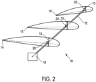
- the components of the measuring system 10 are shown schematically.
- the measuring system 10 comprises a reference shaft 12.
- the reference shaft 12 is arranged in a rotor blade on a leading edge web 13.
- the reference shaft 12 is preferably designed as a hollow shaft so that a low weight and at the same time high rigidity of the reference shaft 12 is achieved.
- the reference shaft 12 has an outer diameter of approximately 25 millimeters and an inner diameter of approximately 21 millimeters.
- profile section 14 schematically showing a profile section in the area of a rotor blade root
- profile section 15 a profile section in an area of the rotor blade center
- profile section 16 a profile section in an area of the rotor blade tip.
- profile 16 in particular which is intended to represent one near the blade tip, is shown enlarged.
- a profile chord is indicated in each of profile sections 14, 15, 16 with a dashed line in order to show a rotation of profile section 16 compared to profile section 15 and profile section 14.
- Profile section 15 is also twisted compared to profile section 14. The rotor blade is therefore twisted.
- the reference shaft 12 is clamped in a shaft holder 18 in a rotationally fixed manner.
- the shaft holder 18 prevents the reference shaft 12 from rotating about its longitudinal axis.
- the reference shaft 12 is clamped in a rotationally fixed manner in the area of the rotor blade root.
- Additional bearings are provided along the reference shaft 12, which fasten the reference shaft 12 to the leading edge web 13.
- the additional bearings are supported by bearing means 22 (see. Fig. 3 ) are formed, which guide the reference shaft 12 but do not hold it in a torsionally rigid manner. The rotor blade can thus be rotated about the reference shaft 12 without the reference shaft 12 twisting when the rotor blade is rotated.
- a plurality of rotation sensors 20 are arranged along the reference shaft 12.
- the rotation sensors 20 are only shown schematically.
- the rotation sensors 20 can be attached to the reference shaft 12 with a marker element and to the leading edge web 13 with a pickup.
- Fig. 2 also shows that the profile sections 14, 15, 16 are twisted to different degrees.
- areas of the rotor blade with different torsion angles can also be determined.
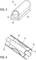
- Fig. 3 shows a schematic view of a bearing means 22.
- a bearing means 22 serves to arrange, guide and support the reference shaft 22 on the leading edge web 13 or another structural element of the rotor blade.
- the bearing means 22 are essentially designed as a tube.
- An inner diameter 24 of a preferred bearing means 22 is approximately 30 millimeters and is thus approximately 5 millimeters larger than the outer diameter of the preferred reference shaft 12. This enables the rotor blade to rotate freely around the reference shaft 12 with little to no friction.
- An outer diameter 26 of a preferred bearing means 22 is approximately 35 millimeters.
- a length 28 of one of the preferred bearing means 22 is approximately 250 millimeters.
- Fig. 4 shows a bearing means 22 arranged on a leading edge web 13.
- the leading edge web 13 has an upper belt 30 and a lower belt 32.
- the bearing means 22 is clamped between the upper belt 30 and the lower belt 32 in order to arrange the reference shaft 12 on the leading edge web 13.
- bearing means 22 are provided approximately at a distance of 2000 to 2500 millimeters along the leading edge web 13 for supporting the reference shaft 12.
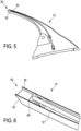
- Fig. 5 shows a leading edge web 13 in a perspective view from a blade root region 51 to a blade tip region 52.
- An upper belt 30 and a lower belt 32 are formed particularly only towards the blade tip region 52.
- Fig. 6 shows an enlarged section of the blade tip area 52 of the leading edge web 13 of the Fig. 5
- a fitting piece 60 is clamped between the upper and lower belt 30, 32 and accommodates the reference shaft 12 in a torsionally rigid manner.
- the Fig. 2 represents a different embodiment.
- the fitting piece 60 thus forms a shaft holder for the reference shaft 12.
- the fitting piece 60 is in its construction very similar to the bearing means 22 of the Fig. 4 , wherein the reference shaft 12 does not extend through the fitting piece 60 and is torsionally rigid.
- Fig. 7 shows a further embodiment of a bearing means 22.
- clamping parts 70 are arranged on the reference shaft 12, which can absorb tensile and shear forces of the reference shaft 12, which is designed as a hollow shaft.
- the clamping parts 70 are intended to prevent the reference shaft 12 from slipping out.
- the clamping parts should be installed in such a way that contact between the clamping parts 70 and the bearing is avoided. In order to keep the friction as low as possible in the event that contact does occur, it is proposed to provide a ball bearing between the clamping part 70 and the bearing means 22 in order to thereby avoid torsion of the reference shaft.
- the reference shaft 12 is pushed onto the leading edge web 13 in the direction of the blade tip.
- the reference shaft 12 is preferably made up of several segments that are connected to one another one after the other.
- the fitting piece 60 is firmly mounted on the end of the reference shaft 12 that is arranged in the area of the blade tip.
- the fastening element 22 is pushed along the leading edge web until it is clamped between the upper belt 30 and the lower belt 32.
- the fastening element 22 is thus fastened to the leading edge web 13 in a form-fitting and force-fitting manner.
- the reference shaft 12 is therefore mounted in a rotationally fixed manner in the area of the blade tip.
- the adapter 60 in the case of a rotationally fixed mounting of the reference shaft 12 in the blade root, the adapter 60 only realizes a final mounting of the reference shaft 12 in the blade tip, but allows a relative rotation of the reference shaft.
- the adapter 60 is designed in such a way that the adapter 60 rotates around the reference shaft 12 when the rotor blade is torsionally torsioned.
- the other bearing means 22 for supporting the reference shaft 12 are gradually pushed on and brought to the specified target position with the help of an auxiliary tube and pushed into place.
- the bearing means 22 are clamped in areas of the rotor blade that are not accessible. In accessible areas, the bearing means 22 are glued.
- a Fig. 7 The bearing element 22 shown must be attached or glued to absorb the tensile forces and thrust forces of the reference shaft 12.
- a corresponding rotation sensor 20 is attached at predetermined positions.
- the torsion angles that occur along the rotor blade radius during operation of the wind turbine are transmitted directly to the rotation sensors 20 along the leading edge web.
- Such a measuring system is not susceptible to a superposition of torsion and bending of the rotor blade, since only a twist is detected by the rotation sensors 20. Since the bearing means 22 do not firmly clamp the reference shaft, the measuring system is also not susceptible to different thermal expansions of the rotor blade and the reference shaft 12. Since the system is permanently integrated in the rotor blade, the torsion angle can be determined at any time during operation of the wind turbine. This means that operating states of the system can be monitored and simulation models that were used to design the rotor blade and/or the wind turbine can be checked and thus improved. The torsion angle can therefore also be used to control the operation of the wind turbine.
- the operating state of the wind turbine can be derived from knowledge of the torsion angle, which is proposed according to an embodiment of the invention.
- the torsion angle can be used to optimize control of the wind turbine with regard to operating loads.
- the torsion angle can also serve as a reference for the power provided by the wind turbine and the sound emitted by the rotor blades.
Landscapes
- Engineering & Computer Science (AREA)
- Physics & Mathematics (AREA)
- General Physics & Mathematics (AREA)
- Aviation & Aerospace Engineering (AREA)
- Chemical & Material Sciences (AREA)
- Sustainable Energy (AREA)
- Sustainable Development (AREA)
- Combustion & Propulsion (AREA)
- Mechanical Engineering (AREA)
- General Engineering & Computer Science (AREA)
- Life Sciences & Earth Sciences (AREA)
- Wind Motors (AREA)
- Length Measuring Devices By Optical Means (AREA)
Description
- Die Erfindung betrifft ein Messsystem sowie ein Verfahren zum Bestimmen einer Torsion eines Rotorblatts. Die Erfindung betrifft weiterhin ein entsprechendes Rotorblatt und ein Verfahren zum Anordnen eines erfindungsgemäßen Messsystems in dem Rotorblatt und darüber hinaus eine entsprechende Windenergieanlage.
- Im Betrieb einer Windenergieanlage rotieren die Rotorblätter um eine im Wesentlichen horizontale Rotorachse. Aufgrund aerodynamischer Effekte, die während der Rotation an den Rotorblättern auftreten, können sich die Rotorblätter verwinden bzw. tordieren. Dabei weist bspw. die Orientierung einer Profilsehne im Bereich der Blattspitze einen Winkel gegenüber der Orientierung einer Profilsehne im Bereich der Blattwurzel auf. Dieser Winkel wird hier als Torsionswinkel bezeichnet und er hängt von den Positionen der Profilsehnen entlang des Rotorblattes ab.
- Wenigstens ein bekanntes Verfahren zum Bestimmen des Torsionswinkels basiert auf der Verwendung eines Kamerasystems. Dazu wird in einem Bereich vor der Windenergieanlage eine Kamera aufgebaut, die auf die Windenergieanlage gerichtet ist. Die Kamera erfasst die Stellung der Rotorblätter, bspw. über an den Rotorblättern angebrachten Markierungen, und kann daraus die Orientierung der Profilsehnen oder eine Verformung des Rotorblattes ableiten. Aus der Orientierung der Profilsehnen zueinander kann dann der Torsionswinkel des Rotorblattes bestimmt werden. Nachteilig bei diesem System ist, dass dieses nur zeitlich begrenzt einsetzbar ist, nämlich wenn der Rotor eine bestimmte Orientierung zu der Kamera aufweist. Des Weiteren ist ein solches System auch mit einem hohen Vorbereitungsaufwand verbunden oder der Windenergieanlagenbetreiber ist von externen Dienstleistern abhängig.
- Andere bekannte Lösungen zum Bestimmen des Torsionswinkels sehen faseroptische Kabel in dem Rotorblatt vor. Das faseroptische Kabel wird dabei mit dem Material des Rotorblattes verklebt. Durch die Verformung bzw. Torsion des Rotorblattes und somit der Verformung bzw. Torsion des Kabels wird eine Polarisation des durch das faseroptische Kabel geleitete Licht bewirkt. Aus der Polarisation kann mittels einer Auswerteeinheit auf den Torsionswinkel geschlossen werden. Bei einem solchen System wurde jedoch eine große Abhängigkeit von dem Biegeverhalten des Rotorblattes festgestellt, wodurch bei Überlagerung von Biegung und Torsion des Rotorblattes fehlerhafte Torsionswinkel bestimmt werden. Darüber hinaus ist ein mit dem Rotorblatt verklebtes Kabel von der Temperaturausdehnung des Rotorblattes beeinflusst. Die Messung erfolgt somit nicht temperaturunabhängig.
- Das Deutsche Patent- und Markenamt hat in der Prioritätsanmeldung zu vorliegender PCT-Anmeldung folgenden Stand der Technik recherchiert:
DE 10 2014 117 914 A1 undUS 2013/0093 879 A1 . - Ein weiteres relevantes Dokument des Standes der Technik ist
DE 10 2007 007047 A1 . - Der vorliegenden Erfindung liegt somit die Aufgabe zugrunde, zumindest eines der oben genannten Probleme zu adressieren. Insbesondere soll eine Lösung vorgeschlagen werden, mit der kontinuierlich der Torsionswinkel erfasst werden kann und außerdem oder alternativ soll eine Lösung vorgeschlagen werden, die unabhängig von einer eventuellen Biegung des Rotorblattes den Torsionswinkel bestimmt. Zumindest soll zu bisherigen Systemen eine alternative Lösung vorgeschlagen werden.
- Erfindungsgemäß werden ein Messsystem zum Bestimmen einer Torsion eines Rotorblattes gemäß Anspruch 1, ein Verhahren gemäß Anspruch 7 und ein Rotorblatt gemäß Anspruch 9 vorgeschlagen.
- Ein solches Messsystem umfasst eine in dem Rotorblatt anzuordnende Referenzwelle und mehrere an der Referenzwelle angeordnete Drehsensoren. Die Referenzwelle ist so gelagert, dass das Rotorblatt frei um die Referenzwelle tordieren kann und so dass die Referenzwelle beim Tordieren des Rotorblattes selber nicht tordiert. Tordiert nun das Rotorblatt während-des Betriebs stellt sich zwischen dem tordierten Rotorblatt und der nicht tordierten Referenzwelle ein Differenzwinkel ein. Die an der Referenzwelle angeordneten Drehsensoren erfassen die Torsion bzw. die Verdrehung des Rotorblattes um die Referenzwelle im Bereich des Drehsensors und geben eine die Verdrehung des Rotorblattes relativ zur Referenzwelle beschreibenden Drehwinkel oder eine andere korrespondierende Größe aus.
- An Stelle des Drehwinkels kann als korrespondierende Größe bspw. eine elektrische Spannung oder ein auf einen maximalen Drehwinkel normierter Wert ausgegeben werden, die bzw. der proportional zum Drehwinkel ist.
- Es wird somit ein Messsystem vorgeschlagen, bei dem sich das Rotorblatt um eine starre Referenzwelle verdreht. Durch Vergleich mit der Referenzwelle kann dadurch an jeder
- Stelle des Rotorblattes, an der ein Drehsensor angeordnet ist, die Verdrehung des Rotorblattes quantitativ erfasst werden.
- Mit einem solchen Messsystem kann kontinuierlich der Torsionswinkel erfasst werden, da der Drehsensor kontinuierlich einen Torsionswinkel des Rotorblattes relativ zu der Referenzwelle erfasst. Ein solches Messsystem ist auch unabhängig von der Ausrichtung des Rotors zu einem externen System, da das Messsystem in dem Rotorblatt integriert ist.
- Erfindungsgemäß ist vorgesehen, dass die Referenzwelle als Hohlwelle ausgebildet ist. Hohlwellen erlauben eine leichte Konstruktion und weisen dennoch eine hohe Steifigkeit insbesondere auch eine hohe Torsionssteifigkeit auf. Ist die Referenzwelle als Hohlwelle ausgebildet, erhöht sich durch das Messsystem das Gewicht des Rotorblattes nur unwesentlich. Das Messsystem beeinflusst somit die Eigenschaften des Rotorblattes kaum.
- Eine weitere Ausführungsform des Messsystems sieht Lagerungsmittel vor, um die Referenzwelle entlang eines Vorderkantensteges des Rotorblattes anzuordnen. Der Vorderkantensteg eines Rotorblattes verläuft im Wesentlichen über die gesamte Länge des Rotorblattes im Bereich der Vorderkante des Rotorblattes. Der Vorderkantensteg stellt in diesem vorderen Bereich eine Verbindung zwischen einer Oberseite und einer Unterseite des Rotorblattes dar und versteift das Rotorblatt, damit das Rotorblatt den angreifenden Windlasten stand hält. Insbesondere tordiert ein Rotorblatt im Wesentlichen um den Vorderkantensteg. Der Vorderkantensteg eignet sich somit sehr gut, um den Torsionswinkel des Rotorblattes zu bestimmen, da hier der Abstand zur Torsionsachse, also der Achse, um die das Rotorblatt tordiert, minimal ist und keine bis geringe Abweichungen auftreten. Der Vorderkantensteg kann sich im Wesentlichen durch das gesamte Rotorblatt erstrecken und eignet sich somit sehr gut dazu, die Referenzwelle aufzunehmen und durch das gesamte Blatt zu führen.
- In einer weiteren Ausführungsform des Messsystems ist eine drehfeste Wellenaufnahme vorgesehen, um ein Ende der Referenzwelle im Bereich einer Rotorblattwurzel oder im Bereich einer Rotorblattspitze drehfest zu befestigen. Durch eine drehfeste Befestigung eines äußeren Endes der Referenzwelle in der Rotorblattspitze wird eine Verdrehung im Bereich der Rotorblattspitze über die drehsteife Referenzwelle zu einem inneren Ende der Referenzwelle übertragen. Dieses innere Ende kann zum Beispiel an der Rotorblattwurzel angeordnet sein oder an einem Ende des Vorderkantenstegs, dass in der Nähe der Rotorblattwurzel angeordnet ist. Dadurch kann die Verdrehung der Rotorblattspitze am inneren Ende der Referenzwelle gemessen werden, also bspw. im Bereich der Rotorblattnabe.
- Es wird außerdem eine gute Installierbarkeit des Messsystems geschaffen, indem die Referenzwelle bspw. in die drehfeste Wellenaufnahme im Bereich der Blattspitze eingeschoben werden kann, oder es kann die Referenzwelle zusammen mit der drehfesten Wellenaufnahme in die Rotorblattspitze eingeschoben werden. Das Problem einer von innen schlecht zugänglichen Blattspitze wird damit zumindest reduziert. Dadurch werden auch Drehsensoren im Bereich der schlecht zugänglichen Rotorblattspitze entbehrlich.
- Die Rotorblattwurzel bildet somit einen Fixpunkt für die Referenzwelle und für die zu erfassende Verdrehung. Das Rotorblatt selbst verdreht sich ausgehend von der Blattwurzel, denn dort ist das Blatt an einer Rotornabe befestigt. Somit wird eine Verdrehung in Bezug auf die Blattwurzel erfasst. Die Referenzwelle bildet eine torsionsfreie Verlängerung der Blattwurzel. Die Erfassung einer Verdrehung relativ zur Referenzwelle ist somit eine Erfassung der Verdrehung relativ zur Blattwurzel.
- Entlang der Referenzwelle wird diese jedoch durch Positionslager so gelagert, dass sie im Wesentlichen nur locker in ihrer Position gehalten wird, wobei lediglich Querkräfte von den Positionslagern weitergeleitet werden, Torsionskräfte aber nicht in die Referenzwelle eingeleitet werden. Somit kann das Rotorblatt an diesen Positionslagern frei um die Referenzwelle tordieren. Ein Verdrehen der Rotorblattspitze gegenüber der Rotorblattwurzel würde einen Drehwinkel zwischen dem verdrehten Rotorblatt in der Blattspitze und der nicht verdrehten Referenzwelle bewirken und einen Torsionswinkel an der Blattspitze anzeigen.
- Alternativ kann vorgesehen sein, dass die Referenzwelle in einem Bereich der Rotorblattwurzel drehfest gelagert ist. Ein Verdrehen der Rotorblattspitze würde nun dazu führen, dass sie sich relativ zur Referenzwelle verdreht. Zum Erfassen der Verdrehung der Blattspitze müsste allerdings auch im Bereich der schlecht zugänglichen Blattspitze der Drehsensor angeordnet sein.
- Genau an einem Ende oder einer anderen Stelle der Referenzwelle muss diese drehfest mit dem Rotorblatt verbunden sein. Das kann bspw. auch in der Mitte sein. Das Messsystem lässt sich somit für verschiedene Typen von Rotorblättern einsetzen, bei denen unterschiedliche Einbausituationen vorliegen.
- Eine Weiterbildung des Messsystems sieht vor, dass die Referenzwelle elektrisch nicht leitend ist. Damit wird besonders ein Blitzschutz erreicht, der verhindert, dass ein Blitz in die Referenzwelle einschlägt, oder dass ein Blitzschlag in der Referenzwelle einen Strom induziert.
- In einer Ausführungsform ist die Referenzwelle aus einem Faserverbundwerkstoff gefertigt. Vorgesehen ist dabei besonders ein mit Aramidfasern oder Kohlenstofffasern verstärkter Kunststoff. Solche Kunststoffe weisen eine hohe Festigkeit bei gleichzeitig geringem Gewicht auf und erlauben somit eine sehr leichte Referenzwelle. Darüber hinaus weisen solche Kunststoffe keinen oder nur einen geringen positiven oder negativen Wärmeausdehnungskoeffizienten auf, so dass die Referenzwelle über einen sehr großen Temperaturbereich wenig Wärmeausdehnung erfährt. Die Messung der Drehsensoren ist somit temperaturunabhängig. Besonders können dadurch auch mechanische Spannungen vermieden werden.
- In einer weiteren Ausgestaltung des Messsystems ist die Referenzwelle axial verschiebbar gelagert. Das kann durch oben bereits genannte Positionslager erfolgen. Somit beeinflussen Ausdehnungen des Rotorblatts aufgrund von Temperaturänderungen oder aus anderen Gründen, nicht die Referenzwelle. Solche Ausdehnungen des Rotorblattes, die auch durch eine Verbiegung des Rotorblattes hervorgerufen sein können, führen nur zu einer relativen axialen Verschiebung zwischen Rotorblatt und Referenzwelle.
- Ein Drehsensor kann besonders aus einem an der Referenzwelle befestigten Markerelement und einem daneben an dem Rotorblatt befestigten Aufnehmer ausgebildet sein. Eine Verdrehung des Rotorblattes im Bereich eines solchen Sensors führt dann zu einer Verdrehung des Markerelementes relativ zu dem Aufnehmer. Das Markerelement kann auch als Geber bezeichnet werden. Der Aufnehmer kann diese relative Verdrehung erfassen und den Referenzwinkel oder eine dazu korrespondierende Größe bestimmen und ausgeben. Das Markerelement kann bspw. als Ringscheibe mit einem Strichcode ausgebildet sein, oder einfach eine Referenzmarkierung aufweisen, die eine Verdrehung erkennen lässt. Je nach Beschaffenheit der Referenzwelle und der Genauigkeitsanforderung kann auch das Markerelement entbehrlich sein und der Aufnehmer unmittelbar eine relative Bewegung der Referenzwelle erfassen.
- Mit einem solchen Drehsensor kann die Position der beiden Abschnitte zueinander, also der Torsionswinkel, sehr genau erfasst werden. Eine reine Biegung der Referenzwelle beeinflusst dabei nicht die Drehwinkelstellung der beiden Abschnitte zueinander. Auch ein leichtes Verschieben entlang der Torsionsachse bspw. durch Temperaturausdehnung beeinflusst die Drehwinkelstellung der beiden Abschnitte zueinander nicht. Nur eine Torsion des Rotorblattes verursacht ein Verdrehen der beiden Abschnitte zueinander, aus der der Torsionswinkel des Rotorblattes bestimmbar ist. Die Torsionswinkelbestimmung ist somit unabhängig von anderen Einflüssen.
- Erfindungsggemäß sind mehrere Drehsensoren zum Erfassen einer Verdrehung des Rotorblattes an mehreren Positionen entlang der Referenzwelle angeordnet. Damit lässt sich der Torsionswinkel an mehreren Positionen entlang des Rotorradius bestimmen. Mehrere Drehsensoren entlang der Referenzwelle ermöglichen ein Erfassen von Bereichen des Rotorblattes, die sich stärker tordieren als andere Bereiche. Eine stärkere Torsion kann aufgrund einer geringeren Steifigkeit des Rotorblattes bspw. in der Blattspitze auftreten. Eine Überbelastung einzelner Bereiche des Rotorblattes kann auf diese Weise ggf. auch erkannt werden.
- Eine weitere Ausführungsform des Messsystems ist dadurch gekennzeichnet, dass die Referenzwelle auf den mehreren Drehsensoren entlang der Blattlängsrichtung gelagert ist, so dass das Rotorblatt um die Referenzwelle rotieren kann. Die Drehsensoren bilden also gleichzeitig die Lagerung der Referenzwelle entlang der Rotorblattlängsrichtung. Das kann besonders einen Drehsensor betreffen, der ein Markerelement und einen Aufnehmer aufweist, wobei die Referenzwelle in dem Aufnehmer des Drehsensors gelagert ist. Somit können zusätzliche Lager und damit zusätzliches Gewicht und/oder zusätzliche Kosten vermieden werden. Die Drehsensoren sollen aber gleichzeitig eine freie Drehung des Rotorblattes um die Referenzwelle gestatten. In einer weiteren Ausgestaltung des Messsystems sind die Lagerungsmittel mit dem Vorderkantensteg verklebt oder verklemmt. Zum Verkleben kann jedes Lagerungsmittel besonders eine flache Klebfläche aufweisen, die mit einem Klebstoff versehen ist, oder versehen werden kann. Dadurch ist eine einfache und robuste Befestigung möglich. Ein Verklemmen der Lagerungsmittel ist insbesondere in solchen Bereichen des Rotorblattes vorgesehen, die zur Montage des Messsystems nicht oder schlecht zugänglich sind. Die Lagerungsmittel sind dazu bspw. auf den Steg aufschiebbar und an eine Geometrie des Vorderkantenstegs angepasst, auf den sie aufgeschoben werden. Mittels eines Hilfsmittels wird das Lagerungsmittel dann bis in den nicht zugänglichen Bereich eingebracht und an der vorgesehenen Position verklemmt. Auf diese Weise ist ein nachträglicher Einbau des Messsystems in Rotorblätter möglich, die bereits im Einsatz sind. An im Rotorblatt zugänglichen Stellen können die Lagerungsmittel zum Anordnen der Referenzwelle an dem Vorderkantensteg verklebt werden. Eine weitere vorteilhafte Ausgestaltung des Messsystems sieht vor, dass wenigstens einer der Drehsensoren als optischer Drehsensor ausgebildet ist. Besonders wird eine optische Abtastung des Markerelementes durch den Aufnehmer vorgeschlagen. Außerdem kommt auch in Betracht, dass einer der Drehsensoren äusschließlich optisch arbeitet und erfasste Werte oder Positionen eines Verdrehwinkels auch optisch, besonders über Lichtwellenleitungen, an eine Auswerteeinheit überträgt, die in der Blattwurzel oder der Rotornabe angeordnet sein kann. Durch die Verwendung solcher optischer Drehsensoren kann ebenfalls ein Schutz oder eine Unanfälligkeit gegen einen Blitzschlag erreicht werden.
- Eine andere Ausgestaltung des Messsystems ist dadurch gekennzeichnet, dass die Referenzwelle aus mehreren Wellensegmenten gebildet wird. Eine solche Ausgestaltung ist zum Einbau oder nachträglichen Einbau des Messsystems in sehr lange Rotorblätter, die eine Länge von über 60 Metern aufweisen können, sehr vorteilhaft, da dadurch die Welle in mehreren Einzelteilen an den Einbauort transportiert werden kann und vor Ort auf die vorgesehene Länge zusammengebaut wird. Die Wellensegmente können bspw. an einander angepasste Enden aufweisen, um ineinander gesteckt zu werden. Dabei sind die angepassten Enden so ausgebildet, dass beim Ineinanderstecken eine drehsteife Steckverbindung entsteht.
- Darüber hinaus schlägt die vorliegende Erfindung ein Verfahren zum Bestimmen einer Torsion eines Rotorblattes nach Anspruch 7 vor. Es arbeitet so, dass eine Torsion des Rotorblatts um eine in dem Rotorblatt in Blattlängsrichtung angeordnete Referenzwelle erfasst wird, die Referenzwelle so in dem Rotorblatt gelagert ist, dass das Rotorblattfrei um die Referenzwelle tordieren kann, so dass die Referenzwelle beim Tordieren des Rotorblattes nicht tordiert, eine Verdrehung durch an der Referenzwelle angeordnete Drehsensoren zum Erfassen einer Verdrehung des Rotorblattes um die Referenzwelle im Bereich des Drehsensors erfasst wird, und mittels des Drehsensors ein die Verdrehung des Rotorblattes relativ zur Referenzwelle beschreibender Drehwinkel oder eine andere korrespondierende Größe ausgegeben wird
- Besonders bevorzugt verwendet das Verfahren ein Messsystem gemäß einer vorstehend beschriebenen Ausführungsform. Außerdem oder alternativ arbeitet das Verfahren so, wie vorstehen im Zusammenhang mit wenigstens einer Ausführungsformeines Messsystems beschrieben wurde.
- Erfindungsgemäß wird der Drehwinkel oder die Verdrehung des Rotorblattes an mehrerer in Blattlängsrichtung verteilten Positionen erfasst. Somit kann der Torsionswinkel an mehreren Positionen des Rotorblattes bestimmt werden und daraus Aufschluss über das Torsionsverhalten in unterschiedlichen Bereichen des Rotorblattes gewonnen werden.
- Eine weitere Ausführungsform des Verfahrens sieht vor, dass der Drehwinkel und/oder die Verdrehung des Rotorblattes zeitlich kontinuierlich erfasst wird. Bspw. werden dafür Daten der Drehsensoren von einem Prozessrechner aufgenommen und besonders weiter verarbeitet. Somit kann der Torsionswinkel ebenfalls zeitlich kontinuierlich bestimmt werden und für eine Regelung der Betriebsführung der Windenergieanlage verwendet werden. Der so erfasste Drehwinkel bzw. die so erfasste Verdrehung des Rotorblattes kann zur weiteren Verarbeitung einer Regelung der Windenergieanlage zugeführt werden.
- Des Weiteren schlägt die vorliegende Erfindung ein Rotorblatt einer Windenergieanlage nach Anspruch 9 vor. Das Rotorblatt umfasst eine Rotorblattwurzel zum Befestigen des Rotorblattes an einer Rotornabe, eine an einer zur Rotorblattwurzel abgewandten Seite des Rotorblattes angeordnete Rotorblattspitze, eine in dem Rotorblatt in Blattlängsrichtung angeordnete Referenzwelle, wenigstens eine Lagerung der Referenzwelle, zum freien Lagern der Referenzwelle in dem Rotorblatt, so dass das Rotorblatt frei um die Referenzwelle tordieren kann, so mehrere dass die Referenzwelle beim Tordieren des Rotorblattes nicht tordiert, und mehrere an der Referenzwelle angeordnete Drehsensoren zum Erfassen einer Verdrehung des Rotorblattes um die Referenzwelle im Bereich des Drehsensors, wobei der Drehsensor einen die Verdrehung des Rotorblattes relativ zur Referenzwelle beschreibenden Drehwinkel oder eine andere korrespondierende Größe ausgibt.
- Ein solches Rotorblatt umfasst besonders ein wie vorstehend gemäß wenigstens einer Ausführungsform beschriebenes Messsystem. Damit kann auf einfache Art und Weise, insbesondere wie vorstehend bereits beschrieben wurde, eine Torsion des Rotorblattes erfasst werden.
- Ein solches Rotorblatt ermöglicht die genaue Bestimmung eines Torsionswinkels des Rotorblattes. Damit lassen sich Rückschlüsse auf die Leistung und den Betriebszustand der Windenergieanlage ableiten. Insbesondere können auch aerodynamische Annahmen und Simulationen der konstruktiven Auslegung des Rotorblattes validiert werden, insbesondere hinsichtlich des Einflusses des Torsionswinkels auf Betriebslasten, die Leistung oder den erzeugten Schall.
- Vorzugsweise ist wenigstens ein von der Rotorblattwurzel in Richtung zur Rotorblattspitze verlaufender Vorderkantensteg vorgesehen, wobei an dem Vorderkantensteg die Referenzwelle und wenigstens ein Abschnitt eines Drehsensors angeordnet sind. Dadurch kann das Messsystem auf einfache Art und Weise in dem Rotorblatt ausgebildet werden, weil der Vorderkantensteg im Wesentlichen von der Blattwurzel zur Blattspitze verläuft und damit eine gute Befestigungsmöglichkeit bzw. Lagerungsmöglichkeit für das Messsystems im Rotorblatt bietet. Gemäß einer weiteren Ausführungsform wird vorgeschlagen, dass die Lagerung der Referenzwelle zwischen zwei Stegen, besonders zwischen zwei Stegen, die nicht den Vorderkantensteg umfassen, und dort an einem dieser Stege erfolgt. Dadurch kann das Messsystem während der Rotorblattfertigung in dem Rotorblatt montiert werden, wenn Formhälften des Rotorblatts noch offen vorliegen. Damit kann auch eine Lagerung der Referenzwelle an dem blattspitzenseitigen Ende vereinfacht werden.
- Eine Ausführungsform des Rotorblattes sieht vor, dass das Rotorblatt in seiner Blattspitze eine Wellenaufnahme zum drehfesten Lagern der Referenzwelle aufweist. Eine solche Wellenaufnahme im Rotorblatt weist den Vorteil auf, das keine zusätzlichen Mittel notwendig sind, die Referenzwelle drehfest an dem Rotorblatt zu befestigen. Eine drehfeste Lagerung der Referenzwelle ist notwendig, da ein Drehwinkel des Rotorblattes gegenüber der Referenzwelle erfasst werden soll.
- Eine weitere Ausführungsform des Rotorblattes ist dadurch gekennzeichnet, dass die Referenzwelle mit einem Passstück in einem Strukturelement des Rotorblattes, besonders in einer Innenkontur des Vorderkantenstegs drehsteif eingeklemmt ist. Dadurch kann eine drehsteife Befestigung auch in der schlecht zugänglichen Rotorblattspitze erreicht werden.
- Dazu bietet sich besonders ein Vorderkantensteg an. Ein solcher Vorderkantensteg weist einen oberen und einen unteren Gurt auf, die einander gegenüber liegend angeordnet und über einen mittleren Stegabschnitt verbunden sind. Dadurch ergibt sich ein Bereich neben dem mittleren Stegabschnitt und den beiden Gurten, in den sich das Passstück einklemmen kann. Dabei ist besonders dort eine gute und haltbare Befestigung, wo sich zwischen den Gurten ein hinterschneidender Bereich ergibt, nämlich besonders dadurch, dass die beiden Gurte nicht genau planparallel verlaufen. Auf diese Weise können auch Lagerungsmittel an dem Vorderkantensteg befestigt werden. Bei den Lagerungsmitteln ist besonders zu beachten, dass diese mit der Referenzwelle nicht viel Gewicht halten müssen.
- Besonders können in unzugänglichen Bereichen des Rotorblattes die Lagerungsmittel in einfacher Weise an die vorgesehene Position geschoben und dort eingeklemmt werden, so dass keine zusätzlichen Mittel notwendig sind die Lagerungsmittel und dadurch die Referenzwelle an dem Vorderkantensteg oder einem anderem Strukturteil des Rotorblattes anzuordnen.
- Eine bevorzugte alternative Ausführungsform des Rotorblatts ist dadurch gekennzeichnet, dass das Rotorblatt in seiner Blattwurzel eine Wellenaufnahme zum drehfesten Lagern der Referenzwelle aufweist. In der Blattwurzel kann die Referenzwelle besonders sicher drehfest gelagert werden und eine solche Lagerung kann auch recht gut überprüft werden. Bei dieser Ausführungsform bleibt die Referenzwelle in Ruhe und das Rotorblatt tordiert um die Referenzwelle. Dadurch wird die Referenzwelle, anders als bei einer Fixierung in der Blattspitze, nicht bei Torsion des Rotorblattes um die eigene Achse gedreht.
- Es wird auch eine Windenergieanlage mit einem erfindungsgemäßen Rotorblatt vorgeschlagen.
- Schließlich schlägt die vorliegende Erfindung auch ein Verfahren zum Montieren eines Messsystems nach einer der vorstehend beschriebenen Ausführungsformen bzw. Ausgestaltungen in einem Rotorblatt einer Windenergieanlage vor.
- Das Verfahren umfasst die Schritte drehsteifes Befestigen eines Passstücks auf einem Blattspitzenabschnitt der Referenzwelle, Einschieben der Referenzwelle mit dem Passstück voran in einen Einbauraum in der Blattspitze des Rotorblattes, entlang eines Strukturelementes, besonders eines Vorderkantenstegs, Aufschieben der Lagerungsmittel auf die Referenzwelle und Befestigen der Lagerungsmittel entlang des Strukturelementes bzw. des Vorderkantenstegs, Anordnen mehrerer Drehsensoren im Bereich der Referenzwelle in dem Rotorblatt. Hier wird besonders die Eigenschaft der drehsteifen Referenzwelle für das Montieren ausgenutzt, indem diese Referenzwelle aus einem begehbaren Bereich des Rotorblattes in den nicht begehbaren und damit schwer zugänglichen Raum in der Nähe der Blattspitze geschoben wird. Gleichzeitig wird die vorhandene Struktur des Rotorblattes dort zum Befestigen ausgenutzt.
- Vorzugsweise werden einige der Lagerungsmittel in einem nicht begehbaren Bereich in der Nähe der Blattspitze durch Festklemmen an dem Strukturelement bzw. in dem Vorderkantensteg befestigt und einige andere der Lagerungsmittel in einem begehbaren Bereich an dem Strukturelement bzw. dem Vorderkantensteg verklebt. Auch dadurch kann die vorhandene Situation im Rotorblatt ausgenutzt werden. Besonders im nicht begehbaren Bereich weist der Vorderkantensteg einen sich zur Blattspitze hin verengenden und oftmals hinterschneidenden Bereich auf, der dazu genutzt werden kann, einige Lagerungsmittel dort so einzuschieben, dass sie dort eingeklemmt werden. Dazu braucht lediglich das jeweilige Lagerungsmittel an die bekannte Größe und Form des Bereichs, in dem das Lagerungsmittel fixiert werden soll, angepasst zu werden. Im begehbaren Bereich, in dem auch der Vorderkantensteg größer ist, kann eine Befestigung durch Verkleben vorgenommen werden. Dort ist auch ausreichend Platz, die Verklebung fachmännisch auszuführen.
- Das Verfahren ermöglicht auch ein Nachrüsten von bereits existierenden Windenergieanlagen mit einem erfindungsgemäßen Messsystem. Darüber hinaus lässt sich damit ein solches Messsystem auch Reparieren bzw. nach einer Reparatur wieder montieren.
- Erfindungsgemäß wird auch vorgeschlagen ein Verfahren nach Anspruch 14 zum Warten oder Reparieren eines in einem Rotorblatt angeordneten Messsystems zum Bestimmen einer Torsion des Rotorblattes, und das Messsystem umfasst
- eine in dem Rotorblatt in Blattlängsrichtung angeordnete Referenzwelle (12),
- wenigstens eine Lagerung der Referenzwelle (12), zum freien Lagern der Referenzwelle (12) in dem Rotorblatt, so dass das Rotorblatt frei um die Referenzwelle (12) tordieren kann, so dass die Referenzwelle (12) beim Tordieren des Rotorblattes nicht tordiert, und
- mehrere an der Referenzwelle angeordnete Drehsensoren (20) zum Erfassen einer Verdrehung des Rotorblattes um die Referenzwelle (12) im Bereich des Drehsensors (20), wobei der Drehsensor (20) einen die Verdrehung des Rotorblattes relativ zur Referenzwelle (12) beschreibenden Drehwinkel oder eine andere korrespondierende Größe ausgibt, umfassend die Schritte:
- Entnehmen der Referenzwelle oder eines Teils davon aus wenigstens einer der Lagerungen,
- Ausbauen dieser wenigstens einen Lagerung und/oder des wenigstens einen Drehsensors,
- Überprüfen der ausgebauten Lagerung bzw. des ausgebauten Drehsensors und
- Wiedereinsetzen der Lagerung bzw. des Drehsensors, oder eines entsprechenden Ersatzteils,
- Wiedereinsetzen der Referenzwelle bzw. des entnommenen Teils davon.
- Hierdurch kann auf einfache Art und Weise eine Wartung oder Reparatur des Messsystems durchgeführt werden. Durch die sukzessiven Schritte können die Elemente einzeln entnommen und inspiziert und ggf. repariert oder ersetzt werden.
- Die Erfindung wird nachfolgend anhand von Ausführungsformen unter Bezugnahme auf die begleitenden Figuren beispielhaft beschrieben.
- Fig. 1
- zeigt perspektivisch eine Windenergieanlage in schematischer Darstellung.
- Fig. 2
- zeigt eine schematische Darstellung einer Ausführungsform eines erfindungsgemäßen Messsystems.
- Fig. 3
- zeigt schematisch ein beispielhaftes Lagerungsmittel.
- Fig. 4
- zeigt schematisch ein in einem Rotorblatt angeordnetes Lagerungsmittel.
- Fig. 5
- zeigt einen Vorderkantensteg in einer perspektivischen Darstellung.
- Fig. 6
- zeigt einen vergrößerten Ausschnitt eines Vorderkantenstegs der
Fig. 5 . - Fig. 7
- zeigt eine weitere Ausführungsform eines Lagermittels.
-
Fig. 1 zeigt eine erfindungsgemäße Windenergieanlage 100 mit einem Turm 102 und einer Gondel 104. An der Gondel 104 ist ein Rotor 106 mit drei erfindungsgemäßen Rotorblättern 108 und einem Spinner 110 angeordnet. Der Rotor 106 wird im Betrieb durch den Wind in eine Drehbewegung versetzt und treibt dadurch einen Generator in der Gondel 104 an. Während der Rotation können die Rotorblätter 108 tordieren. Zum Erkennen und Bestimmen der Torsion der Rotorblätter 108 ist in den Rotorblättern 108 ein Messsystem montiert. - In
Fig. 2 sind schematisch die Komponenten des Messsystems 10 dargestellt. Das Messsystem 10 umfasst eine Referenzwelle 12. Die Referenzwelle 12 ist in einem Rotorblatt an einem Vorderkantensteg 13 angeordnet. Die Referenzwelle 12 ist vorzugsweise als Hohlwelle ausgebildet, so dass ein geringes Gewicht bei gleichzeitig hoher Steifigkeit der Referenzwelle 12 erzielt wird. Die Referenzwelle 12 weist einen Außendurchmesser von ungefähr 25 Millimeter und einen Innendurchmesser von ungefähr 21 Millimeter auf. - Von dem Rotorblatt sind zur besseren Übersicht nur drei schematische Profilschnitte 14, 15, 16 dargestellt, wobei der Profilschnitt 14 einen Profilschnitt im Bereich einer Rotorblattwurzel, der Profilschnitt 15 einen Profilschnitt in einem Bereich der Rotorblattmitte und der Profilschnitt 16 einen Profilschnitt in einem Bereich der Rotorblattspitze schematisch darstellt. Der besseren Übersichtlichkeit halber ist besonders das Profil 16, das eines in der Nähe der Blattspitze darstellen soll, vergrößert dargestellt. Mit gestrichelter Linie ist in den Profilschnitten 14, 15, 16 jeweils noch eine Profilsehne angedeutet, um eine Verdrehung des Profilschnitts 16 gegenüber dem Profilschnitt 15 und dem Profilschnitt 14 darzustellen. Auch der Profilschnitt 15 ist gegenüber dem Profilschnitt 14 verdreht. Das Rotorblatt ist somit tordiert.
- An einem Ende ist die Referenzwelle 12 in einer Wellenaufnahme 18 drehfest eingespannt. Die Wellenaufnahme 18 verhindert eine Drehbewegung der Referenzwelle 12 um ihre Längsachse. In dem gezeigten Ausführungsbeispiel ist die Referenzwelle 12 im Bereich der Rotorblattwurzel drehfest eingespannt. Weitere Lager sind entlang der Referenzwelle 12 vorgesehen, die die Referenzwelle 12 an dem Vorderkantensteg 13 befestigen. Die weiteren Lager werden durch Lagerungsmittel 22 (s.
Fig. 3 ) gebildet, die die Referenzwelle 12 führen, aber nicht drehsteif festhalten. Somit ist das Rotorblatt um die Referenzwelle 12 verdrehbar, ohne dass die Referenzwelle 12 bei einem Verdrehen des Rotorblattes tordiert. - Entlang der Referenzwelle 12 sind mehrere Drehsensoren 20 angeordnet. Die Drehsensoren 20 sind lediglich schematisch dargestellt. Die Drehsensoren 20 können mit einem Markerelement an der Referenzwelle 12 und mit einem Aufnehmer an dem Vorderkantensteg 13 befestigt sein.
-
Fig. 2 verdeutlicht auch, dass die Profilschnitte 14, 15, 16 unterschiedlich stark verdreht sind. Mit mehreren entlang der Referenzwelle 12 angeordneten Drehsensoren 20 können somit auch Bereiche des Rotorblattes mit unterschiedlich ausgeprägtem Torsionswinkel bestimmt werden. -
Fig. 3 zeigt eine schematische Ansicht eines Lagerungsmittels 22. Ein solches Lagerungsmittel 22 dient dem Anordnen, Führen und Lagern der Referenzwelle 22 an dem Vorderkantensteg 13 oder einem anderen Strukturelement des Rotorblattes. Die Lagerungsmittel 22 sind im Wesentlichen als Rohr ausgebildet. Ein Innendurchmesser 24 eines bevorzugten Lagerungsmittels 22 beträgt ungefähr 30 Millimeter und ist damit um ungefähr 5 Millimeter größer als der Außendurchmesser der bevorzugten Referenzwelle 12. Dadurch ist ein freies Rotieren des Rotorblattes um die Referenzwelle 12 mit wenig bis gar keiner Reibung möglich. Ein Außendurchmesser 26 eines bevorzugten Lagerungsmittels 22 beträgt ungefähr 35 Millimeter. Eine Länge 28 eines des bevorzugten Lagerungsmittels 22 beträgt ungefähr 250 Millimeter. -
Fig. 4 zeigt ein Lagerungsmittel 22, das an einem Vorderkantensteg 13 angeordnet ist. Der Vorderkantensteg 13 weist einen oberen Gurt 30 und einen unteren Gurt 32 auf. Zwischen dem oberen Gurt 30 und dem unteren Gurt 32 ist das Lagerungsmittel 22 eingeklemmt, um die Referenzwelle 12 an dem Vorderkantensteg 13 anzuordnen. Zum Verhindern einer großen Durchbiegung der Referenzwelle 12 sind Lagerungsmittel 22 ungefähr in einem Abstand von 2000 bis 2500 Millimeter entlang des Vorderkantenstegs 13 zum Lagern der Referenzwelle 12 vorgesehen. -
Fig. 5 zeigt einen Vorderkantensteg 13 in einer perspektivischen Darstellung von einem Blattwurzelbereich 51 zu einem Blattspitzenbereich 52. Ein oberer Gurt 30 und ein unterer Gurt 32 bilden sich besonders erst zum Blattspitzenbereich 52 aus. -
Fig. 6 zeigt einen vergrößerten Ausschnitt des Blattspitzenbereichs 52 des Vorderkantenstegs 13 derFig. 5 . Dort ist zu erkennen, dass zwischen dem oberen und unteren Gurt 30, 32 ein Passstück 60 eingeklemmt ist und die Referenzwelle 12 drehsteif aufnimmt. Insoweit stellt das zuFig. 2 ein abweichende Ausführungsform dar. Das Passstück 60 bildet somit eine Wellenaufnahme für die Referenzwelle 12. Das Passstück 60 ist in seinem Aufbau ganz ähnlich dem Lagerungsmittel 22 derFig. 4 , wobei die Referenzwelle 12 durch das Passstück 60 nicht hindurch reicht und drehsteif aufgenommen ist. -
Fig. 7 zeigt eine weitere Ausführungsform eines Lagerungsmittels 22. Dabei sind zusätzlich Klemmteile 70 auf der Referenzwelle 12 angeordnet, die Zug- und Schubkräfte der Referenzwell 12, die als Hohlwelle ausgebildet ist, aufnehmen können. Die Klemmteile 70 sollen ein Herausrutschen der Referenzwelle 12 verhindern. Die Klemmteile sollten möglichst so installiert werden, dass ein Kontakt der Klemmteile 70 mit der Lagerung vermieden wird. Um in dem Fall, dass doch eine Berührung auftritt, die Reibung möglichst klein zu halten, wird vorgeschlagen, eine Kugellagerung zwischen Klemmteil 70 und Lagerungsmittel 22 vorzusehen, um dadurch eine Torsion der Referenzwelle zu vermeiden. - Im Übrigen können zur Vereinfachung für die gezeigten Ausführungsformen gleiche Bezugszeichen für ähnliche aber nicht unbedingt identische Elemente verwendet werden.
- Zur Montage des Messsystems 10 wird die Referenzwelle 12 auf dem Vorderkantensteg 13 in Richtung Blattspitze eingeschoben. Hierzu ist die Referenzwelle 12 vorzugsweise aus mehreren Segmenten gebildet, die einzeln nacheinander miteinander verbunden werden. An dem Ende der Referenzwelle 12, das im Bereich der Blattspitze angeordnet wird, ist das Passstück 60 fest montiert. Das Befestigungselement 22 wird so weit entlang des Vorderkantenstegs eingeschoben, bis es zwischen dem oberen Gurt 30 und dem unteren Gurt 32 eingeklemmt ist. Das Befestigungselement 22 wird also formschlüssig und kraftschlüssig an dem Vorderkantensteg 13 befestigt. Bei dieser Ausführungsform ist die Referenzwelle 12 also im Bereich der Blattspitze drehfest montiert.
- Alternativ ist jedoch vorgesehen, dass bei einer drehfesten Lagerung der Referenzwelle 12 in der Blattwurzel, das Passstück 60 lediglich eine abschließende Lagerung der Referenzwelle 12 in der Blattspitze realisiert, eine relative Drehung der Referenzwelle aber zulässt. Dabei ist das Passstück 60 so ausgebildet, dass sich das Passstück 60 bei einer Torsion des Rotorblatts um die Referenzwelle 12 dreht.
- Nachdem die Referenzwelle 12 montiert ist, werden nach und nach die weiteren Lagerungsmittel 22 zum Lagern der Referenzwelle 12 aufgeschoben und mit Hilfe eines Hilfsrohres bis an die vorgegebene Sollposition verbracht und festgestoßen. Ein Klemmen der Lagerungsmittel 22 erfolgt in Bereichen des Rotorblattes, die nicht zugänglich sind. In zugänglichen Bereichen werden die Lagerungsmittel 22 verklebt. Auf dem letzten Segment der Referenzwelle 12 kann ein wie in
Fig. 7 gezeigtes Lagerungselement 22 zur Aufnahme der Zugkräfte und Schubkräfte der Referenzwelle 12 angebracht bzw. verklebt sein. - An vorgegebenen Positionen wird jeweils ein entsprechender Drehsensor 20 angebracht.
- Durch die feste Einspannung der Referenzwelle 12 an einem Ende des Vorderkantenstegs 13 werden die Torsionswinkel, welche sich im Betrieb der Windenergieanlage entlang des Rotorblattradius einstellen, direkt an die Drehsensoren 20 entlang des Vorderkantenstegs übertragen. Ein solches Messsystem ist unanfällig für eine Überlagerung von Torsion und Biegung des Rotorblattes, da ausschließlich eine Verdrehung von den Drehsensoren 20 erfasst wird. Da die Lagerungsmittel 22 die Referenzwelle nicht fest einspannen, ist das Messsystem auch unanfällig für unterschiedliche Wärmeausdehnungen des Rotorblattes und der Referenzwelle 12. Da das System in dem Rotorblatt dauerhaft integriert ist, kann zu jedem Zeitpunkt im Betrieb der Windenergieanlage der Torsionswinkel bestimmt werden. Somit können Betriebszustände der Anlage überwacht und Simulationsmodelle, die zur Auslegung des Rotorblattes und/oder der Windenergieanlage herangezogen wurden, nachgeprüft und dadurch verbessert werden. Der Torsionswinkel kann dadurch auch zur Regelung der Betriebsführung der Windenergieanlage verwendet werden.
- Vorteilhaft ist auch, dass aus der Kenntnis des Torsionswinkels ein Betriebszustand der Windenergieanlage ableitbar ist, was gemäß einer erfindungsgemäßen Ausführung vorgeschlagen wird. Darüber hinaus kann mit Hilfe des Torsionswinkels eine Regelung der Windenergieanlage hinsichtlich Betriebslasten optimiert werden. Der Torsionswinkel kann auch als Referenz der von der Windenergieanlage erbrachten Leistung und des von den Rotorblättern abgegebenen Schalls dienen.
-
- 1. Messsystem (10) zum Bestimmen einer Torsion eines Rotorblattes, umfassend
- eine in dem Rotorblatt in Blattlängsrichtung anzuordnende Referenzwelle (12),
- wenigstens eine Lagerung der Referenzwelle (12), zum freien Lagern der Referenzwelle (12) in dem Rotorblatt, so dass das Rotorblattfrei um die Referenzwelle (12) tordieren kann, so dass die Referenzwelle (12) beim Tordieren des Rotorblattes nicht tordiert,
- wenigstens einen an der Referenzwelle angeordneten Drehsensor (20) zum Erfassen einer Verdrehung des Rotorblattes um die Referenzwelle (12) im Bereich des Drehsensors (20), wobei der Drehsensor (20) einen die Verdrehung des Rotorblattes relativ zur Referenzwelle (12) beschreibenden Drehwinkel oder eine andere korrespondierende Größe ausgibt, dadurch gekennzeichnet, dass
- die Referenzwelle (12) als Hohlwelle ausgebildet ist.
- 2. Messsystem (10) nach Anspruch 1,
Claims (15)
- Messsystem (10) zum Bestimmen einer Torsion eines Rotorblattes, umfassend- eine in dem Rotorblatt in Blattlängsrichtung anzuordnende Referenzwelle (12),- wenigstens eine Lagerung der Referenzwelle (12), zum freien Lagern der Referenzwelle (12) in dem Rotorblatt, so dass das Rotorblatt frei um die Referenzwelle (12) tordieren kann, so dass die Referenzwelle (12) beim Tordieren des Rotorblattes nicht tordiert,- wenigstens einen an der Referenzwelle angeordneten Drehsensor (20) zum Erfassen einer Verdrehung des Rotorblattes um die Referenzwelle (12) im Bereich des Drehsensors (20), wobei der Drehsensor (20) einen die Verdrehung des Rotorblattes relativ zur Referenzwelle (12) beschreibenden Drehwinkel oder eine andere korrespondierende Größe ausgibt, dadurch gekennzeichnet, dass- die Referenzwelle (12) als Hohlwelle ausgebildet ist, und- mehrere Drehsensoren zum Erfassen einer Verdrehung des Rotorblattes an mehreren Positionen entlang der Referenzwelle angeordnet sind.
- Messsystem (10) nach Anspruch 1, dadurch gekennzeichnet, dass
Lagerungsmittel (22) vorgesehen sind, um die Referenzwelle (12) entlang eines Vorderkantensteges (13) des Rotorblattes anzuordnen und/oder die Lagerungsmittel (22) dazu vorbereitet sind, an dem Vorderkantensteg (13) verklebt oder verklemmt zu werden. - Messsystem (10) nach Anspruch 1 oder 2, dadurch gekennzeichnet, dass
eine drehfeste Wellenaufnahme (18) vorgesehen ist, um ein Ende der Referenzwelle (12) im Bereich einer Rotorblattspitze drehfest zu befestigen und/oder die Referenzwelle (12) axial verschiebbar angeordnet ist. - Messsystem (10) nach einem der vorstehenden Ansprüche, dadurch gekennzeichnet, dass
die Referenzwelle (12) elektrisch nichtleitend und/oder aus einem Faserverbundwerkstoff gefertigt ist, insbesondere aus mit Aramidfasern oder Kohlenstofffasern verstärktem Kunststoff, wobei die Referenzwelle (12) insbesondere aus mehreren Wellensegmenten zusammengesetzt ist. - Messsystem (10) nach einem der vorstehenden Ansprüche, dadurch gekennzeichnet, dassder Drehsensor (20) als optischer Drehsensor ausgebildet ist und/oder ein Markerelement aufweist, das zum Befestigen an der Referenzwelle vorbereitet ist, undeinen Aufnehmer, der zum Befestigen an dem Vorderkantensteg (13) des Rotorblattes oder einem anderen Strukturelement des Rotorblattes vorbereitet ist, und wobei der Aufnehmer dazu vorbereitet ist, eine Verdrehung des Markerelementes relativ zu dem Aufnehmer zu erfassen, um dadurch eine Verdrehung des Rotorblatts relativ zur Referenzwelle an dieser Stelle zu erfassen.
- Messsystem (10) nach einem der vorstehenden Ansprüche, dadurch gekennzeichnet, dass
die Referenzwelle (12) auf den mehreren Drehsensoren (20) entlang der Blattlängsrichtung gelagert ist. - Verfahren zum Bestimmen einer Torsion eines Rotorblattes wobei- eine Torsion des Rotorblatts um eine in dem Rotorblatt in Blattlängsrichtung angeordnete Referenzwelle (12) erfasst wird,- die Referenzwelle so in dem Rotorblatt gelagert ist, dass das Rotorblatt frei um die Referenzwelle (12) tordieren kann, so dass die Referenzwelle (12) beim Tordieren des Rotorblattes nicht tordiert,- eine Verdrehung durch wenigstens einen an der Referenzwelle angeordneten Drehsensor (20) zum Erfassen einer Verdrehung des Rotorblattes um die Referenzwelle (12) im Bereich des Drehsensors (20) erfasst wird, und- mittels des Drehsensors (20) ein die Verdrehung des Rotorblattes relativ zur Referenzwelle (12) beschreibender Drehwinkel oder eine andere korrespondierende Größe ausgegeben wird, und dadurch gekennzeichnet, dass- der Drehwinkel oder die Verdrehung des Rotorblattes an mehreren in Blattlängsrichtung verteilter Positionen erfasst wird, und- mehrere Drehsensoren zum Erfassen einer Verdrehung des Rotorblattes an mehreren Positionen entlang der Referenzwelle angeordnet sind.
- Verfahren nach Anspruch 7, dadurch gekennzeichnet, dass
ein Messsystem gemäß einem der Ansprüche 1 bis 6 verwendet wird, wobei insbesondere der Drehwinkel und/oder die Verdrehung des Rotorblattes zeitlich kontinuierlich erfasst wird. - Rotorblatt einer Windenergieanlage und das Rotorblatt umfasst- eine Rotorblattwurzel zum Befestigen des Rotorblattes an einer Rotornabe,- eine an einer zur Rotorblattwurzel abgewandten Seite des Rotorblattes angeordnete Rotorblattspitze,- eine in dem Rotorblatt in Blattlängsrichtung angeordnete Referenzwelle (12),- wenigstens eine Lagerung der Referenzwelle (12), zum freien Lagern der Referenzwelle (12) in dem Rotorblatt, so dass das Rotorblatt frei um die Referenzwelle (12) tordieren kann, so dass die Referenzwelle (12) beim Tordieren des Rotorblattes nicht tordiert, und- wenigstens einen an der Referenzwelle angeordneten Drehsensor (20) zum Erfassen einer Verdrehung des Rotorblattes um die Referenzwelle (12) im Bereich des Drehsensors (20), wobei der Drehsensor (20) einen die Verdrehung des Rotorblattes relativ zur Referenzwelle (12) beschreibenden Drehwinkel oder eine andere korrespondierende Größe ausgibt, dadurch gekennzeichnet, dass- die Referenzwelle (12) als Hohlwelle ausgebildet ist, und- mehrere Drehsensoren zum Erfassen einer Verdrehung des Rotorblattes an mehreren Positionen entlang der Referenzwelle angeordnet sind.
- Rotorblatt nach Anspruch 9, dadurch gekennzeichnet, dass
ein von der Rotorblattwurzel in Richtung zur Rotorblattspitze verlaufender Vorderkantensteg (13) vorgesehen ist, und an dem Vorderkantensteg (13) die Referenzwelle (12) und wenigstens ein Abschnitt des Drehsensors angeordnet sind. - Rotorblatt nach Anspruch 9 oder 10, dadurch gekennzeichnet, dass
ein Messsystem (10) nach einem der Ansprüche 1 bis 6 verwendet wird und die Referenzwelle (12), die wenigstens eine Lagerung der Referenzwelle (12) und der wenigstens eine Drehsensor (20) Elemente dieses Messsystems sind. - Rotorblatt nach Anspruch 11, dadurch gekennzeichnet, dassdas Rotorblatt in seiner Blattspitze eine Wellenaufnahme (18) zum drehfesten Lagern der Referenzwelle (12) aufweist, und insbesondere die Referenzwelle (12) mit einem Passstück in einem Strukturelement des Rotorblattes, besonders in einer Innenkontur eines bzw. des Vorderkantenstegs (13) drehsteif eingeklemmt ist, oderdas Rotorblatt in seiner Blattwurzel eine Wellenaufnahme (18) zum drehfesten Lagern der Referenzwelle (12) aufweist.
- Verfahren zum Montieren eines Messsystems (10) nach einem der Ansprüche 1 bis 6 in einem Rotorblatt einer Windenergieanlage, umfassend die Schritte- drehsteifes Befestigen eines Passstücks auf einem Blattspitzenabschnitt der Referenzwelle (12),- Einschieben der Referenzwelle (12) mit dem Passstück voran in einen Einbauraum in der Blattspitze des Rotorblattes, entlang eines Strukturelementes, besonders eines Vorderkantenstegs (13),- Aufschieben der Lagerungsmittel (22) auf die Referenzwelle (12) und Befestigen der Lagerungsmittel (22) entlang des Strukturelementes bzw. des Vorderkantenstegs (13),- Anordnen des wenigstens einen Drehsensors (20) im Bereich der Referenzwelle (12) in dem Rotorblatt, wobei insbesondere- einige der Lagerungsmittel in einem nicht begehbaren Bereich in der Nähe der Blattspitze durch Festklemmen an dem Strukturelement bzw. in dem Vorderkantensteg befestigt werden und- einige andere der Lagerungsmittel in einem begehbaren Bereich an dem Strukturelement bzw. dem Vorderkantensteg verklebt werden.
- Verfahren zum Warten oder Reparieren eines in einem Rotorblatt angeordneten Messsystems zum Bestimmen einer Torsion des Rotorblattes, und das Messsystem umfasst- eine in dem Rotorblatt in Blattlängsrichtung angeordnete Referenzwelle (12),- wenigstens eine Lagerung der Referenzwelle (12), zum freien Lagern der Referenzwelle (12) in dem Rotorblatt, so dass das Rotorblatt frei um die Referenzwelle (12) tordieren kann, so dass die Referenzwelle (12) beim Tordieren des Rotorblattes nicht tordiert, und- wenigstens einen an der Referenzwelle angeordneten Drehsensor (20) zum Erfassen einer Verdrehung des Rotorblattes um die Referenzwelle (12) im Bereich des Drehsensors (20), wobei der Drehsensor (20) einen die Verdrehung des Rotorblattes relativ zur Referenzwelle (12) beschreibenden Drehwinkel oder eine andere korrespondierende Größe ausgibt, umfassend die Schritte:- Entnehmen der Referenzwelle oder eines Teils davon aus wenigstens einer der Lagerungen,- Ausbauen dieser wenigstens einen Lagerung und/oder des wenigstens einen Drehsensors,- Überprüfen der ausgebauten Lagerung bzw. des ausgebauten Drehsensors und- Wiedereinsetzen der Lagerung bzw. des Drehsensors, oder eines entsprechenden Ersatzteils,- Wiedereinsetzen der Referenzwelle bzw. des entnommenen Teils davon, wobei als Messsystem ein Messsystem nach einem der Ansprüche 1 bis 6 verwendet wird.
- Windenergieanlage umfassend wenigstens ein Rotorblatt nach einem der Ansprüche 9 bis 12 und außerdem oder alternativ einem Messsystem (10) nach einem der Ansprüche 1 bis 6.
Applications Claiming Priority (2)
| Application Number | Priority Date | Filing Date | Title |
|---|---|---|---|
| DE102016112633.0A DE102016112633A1 (de) | 2016-07-11 | 2016-07-11 | Torsionswinkelmessung eines Rotorblatts |
| PCT/EP2017/066764 WO2018011034A1 (de) | 2016-07-11 | 2017-07-05 | Torsionswinkelmessung eines rotorblatts |
Publications (3)
| Publication Number | Publication Date |
|---|---|
| EP3482182A1 EP3482182A1 (de) | 2019-05-15 |
| EP3482182B1 EP3482182B1 (de) | 2021-09-08 |
| EP3482182B2 true EP3482182B2 (de) | 2025-02-19 |
Family
ID=59285226
Family Applications (1)
| Application Number | Title | Priority Date | Filing Date |
|---|---|---|---|
| EP17735522.9A Active EP3482182B2 (de) | 2016-07-11 | 2017-07-05 | Torsionswinkelmessung eines rotorblatts |
Country Status (11)
| Country | Link |
|---|---|
| US (1) | US20190234829A1 (de) |
| EP (1) | EP3482182B2 (de) |
| JP (1) | JP6617212B2 (de) |
| KR (1) | KR20190021433A (de) |
| CN (1) | CN109416295A (de) |
| BR (1) | BR112018076900A2 (de) |
| CA (1) | CA3027689A1 (de) |
| DE (1) | DE102016112633A1 (de) |
| DK (1) | DK3482182T4 (de) |
| RU (1) | RU2019103390A (de) |
| WO (1) | WO2018011034A1 (de) |
Families Citing this family (8)
| Publication number | Priority date | Publication date | Assignee | Title |
|---|---|---|---|---|
| CN111256636B (zh) * | 2018-11-30 | 2021-11-19 | 上海电气电站设备有限公司 | 一种叶片扭转量的测量方法 |
| CN109958483B (zh) * | 2019-03-17 | 2021-07-09 | 中国航发沈阳发动机研究所 | 一种发动机运行状态转子叶片扭转角度测量系统及方法 |
| CN110514169B (zh) * | 2019-08-29 | 2021-08-24 | 三一重能有限公司 | 风机叶片安装角的检查方法、装置、存储介质及电子设备 |
| CN113027697B (zh) * | 2019-12-24 | 2025-07-04 | 金风科技股份有限公司 | 一种风力发电机组叶片桨距角的测量系统、方法和装置 |
| GB202009315D0 (en) | 2020-06-18 | 2020-08-05 | General Electric Renovables Espana Sl | A wind turbine blade measurement system and a method of improving accuracy of a wind turbine blade measurement system |
| CN112525034B (zh) * | 2020-12-09 | 2025-02-11 | 贵州西南工具(集团)有限公司 | 一种智能化叶片尺寸无损检测机构 |
| CN112414324B (zh) * | 2020-12-22 | 2022-10-14 | 南昌航空大学 | 一种基于双目立体视觉的直升机旋翼桨叶扭转角测量方法 |
| EP4565783A1 (de) * | 2022-08-04 | 2025-06-11 | LM Wind Power A/S | Windturbinenschaufel, windenergieanlage und verfahren zum betreiben einer windenergieanlage |
Family Cites Families (22)
| Publication number | Priority date | Publication date | Assignee | Title |
|---|---|---|---|---|
| WO2003029750A1 (en) * | 2001-10-02 | 2003-04-10 | Vestas Wind Systems A/S | Sensor construction for measuring the bending of a construction element |
| DE10259680B4 (de) * | 2002-12-18 | 2005-08-25 | Aloys Wobben | Rotorblatt einer Windenergieanlage |
| RU2304232C2 (ru) * | 2004-04-29 | 2007-08-10 | Рауиль Абдул-Хакимович Шахмаметов | Ветроэнергетическая установка |
| US7059822B2 (en) | 2004-06-30 | 2006-06-13 | General Electrick Company | Methods and apparatus for measuring wind turbine blade deflection |
| DE102007007047A1 (de) * | 2007-02-08 | 2008-08-14 | Hottinger Baldwin Messtechnik Gmbh | Vorrichtung zur Erfassung von Schwingungen oder Durchbiegungen von Rotorblättern einer Windkraftanlage |
| DK2037212T3 (en) | 2007-09-12 | 2016-03-29 | Siemens Ag | Method and sensor device for determining bending and / or load |
| ES2337645B1 (es) * | 2007-09-14 | 2011-03-11 | GAMESA INNOVATION & TECHNOLOGY, S.L. | Union de pala sensorizada. |
| GB2465790A (en) | 2008-11-28 | 2010-06-02 | Vestas Wind Sys As | System to measure load on a wind turbine blade |
| EP2392818A1 (de) * | 2009-01-30 | 2011-12-07 | Gamesa Innovation & Technology, S.L. | System zur messung von deformationen bei windturbinenschaufeln während einer statischen prüfung |
| EP2339173B1 (de) * | 2009-12-22 | 2015-04-01 | Siemens Aktiengesellschaft | Schaufelbiegungsmessung mit magnetostriktivem Sensor |
| GB2479923A (en) * | 2010-04-29 | 2011-11-02 | Vestas Wind Sys As | A method and system for detecting angular deflection in a wind turbine blade, or component, or between wind turbine components |
| DE102010017749A1 (de) * | 2010-07-05 | 2012-01-05 | Ssb Wind Systems Gmbh & Co. Kg | Vorrichtung zur optischen Messung der Biegung eines Rotorblatts einer Windkraftanlage |
| GB2487072A (en) * | 2011-01-06 | 2012-07-11 | Vestas Wind Sys As | Method of detecting damage to a wind turbine component during transport |
| EP2485011B1 (de) * | 2011-02-07 | 2013-08-28 | Siemens Aktiengesellschaft | Anordnung zum Messen einer Abweichung eines Objekts |
| EP2511524A1 (de) | 2011-04-11 | 2012-10-17 | Baumer Innotec AG | Verfahren und Vorrichtung zum Überwachen eines Rotorblatts für eine Windkraftanlage |
| DE102011083746B3 (de) | 2011-09-29 | 2013-04-04 | Aktiebolaget Skf | Vorrichtung und Verfahren zum Erfassen eines Abstandswertes |
| US20130302161A1 (en) * | 2012-05-08 | 2013-11-14 | Arne Koerber | Controller of wind turbine and wind turbine |
| ES2630061T3 (es) * | 2012-08-17 | 2017-08-17 | Lm Wp Patent Holding A/S | Sistema de monitorización de deflexión de palas |
| DE102012108776A1 (de) * | 2012-09-18 | 2014-03-20 | Technische Universität München | Verfahren und Vorrichtung zur Überwachung von Betriebszuständen von Rotorblättern |
| EP2848805B1 (de) | 2013-09-17 | 2019-01-02 | Alstom Renovables España, S.L. | Verfahren zum Betrieb einer Windturbine |
| DE102014117914B4 (de) * | 2014-12-04 | 2021-11-11 | fos4X GmbH | Verfahren zur Erfassung eines Flatterns eines Rotorblatts einer Windkraftanlage |
| CN104963810A (zh) * | 2015-07-02 | 2015-10-07 | 国电联合动力技术有限公司 | 一种风力发电机组低风速发电优化控制方法及系统 |
-
2016
- 2016-07-11 DE DE102016112633.0A patent/DE102016112633A1/de not_active Withdrawn
-
2017
- 2017-07-05 CA CA3027689A patent/CA3027689A1/en not_active Abandoned
- 2017-07-05 DK DK17735522.9T patent/DK3482182T4/da active
- 2017-07-05 CN CN201780042806.9A patent/CN109416295A/zh active Pending
- 2017-07-05 EP EP17735522.9A patent/EP3482182B2/de active Active
- 2017-07-05 US US16/316,561 patent/US20190234829A1/en not_active Abandoned
- 2017-07-05 JP JP2018568332A patent/JP6617212B2/ja not_active Expired - Fee Related
- 2017-07-05 WO PCT/EP2017/066764 patent/WO2018011034A1/de not_active Ceased
- 2017-07-05 KR KR1020197002563A patent/KR20190021433A/ko not_active Ceased
- 2017-07-05 RU RU2019103390A patent/RU2019103390A/ru unknown
- 2017-07-05 BR BR112018076900-2A patent/BR112018076900A2/pt not_active Application Discontinuation
Also Published As
| Publication number | Publication date |
|---|---|
| RU2019103390A3 (de) | 2020-08-11 |
| EP3482182B1 (de) | 2021-09-08 |
| EP3482182A1 (de) | 2019-05-15 |
| DK3482182T3 (da) | 2021-10-04 |
| JP6617212B2 (ja) | 2019-12-11 |
| CA3027689A1 (en) | 2018-01-18 |
| RU2019103390A (ru) | 2020-08-11 |
| WO2018011034A1 (de) | 2018-01-18 |
| BR112018076900A2 (pt) | 2019-03-26 |
| DK3482182T4 (da) | 2025-03-03 |
| US20190234829A1 (en) | 2019-08-01 |
| DE102016112633A1 (de) | 2018-01-11 |
| CN109416295A (zh) | 2019-03-01 |
| JP2019522798A (ja) | 2019-08-15 |
| KR20190021433A (ko) | 2019-03-05 |
Similar Documents
| Publication | Publication Date | Title |
|---|---|---|
| EP3482182B2 (de) | Torsionswinkelmessung eines rotorblatts | |
| DE102006054667B4 (de) | Kollisionswarnsystem für eine Windenergieanlage | |
| EP3227690B1 (de) | Verfahren zur überwachung einer windkraftanlage, verfahren zur eiserkennung an einer windkraftanlage, beschleunigungssensor für ein rotorblatt, rotorblatt mit beschleunigungssensor, und profil für ein rotorblatt | |
| EP3513069B1 (de) | Verfahren und vorrichtung zur ermittlung von belastungen auf einen turm einer windenergieanlage | |
| EP3227552B1 (de) | Verfahren zur individuellen pitchregelung von rotorblättern einer windkraftanlage und windkraftanlagen | |
| EP3913215B1 (de) | Verfahren zum ausmessen eines rotorblattwinkels | |
| DE102007059165A1 (de) | Verfahren und System zur Messung einer Auslenkung eines Hohlbauteils einer Windenergieanlage aus einer Normalposition | |
| WO2013045612A1 (de) | Vorrichtung und verfahren zum erfassen eines abstandswertes | |
| DE10219664A1 (de) | Windenergieanlage, Regelanordnung für eine Windenergieanlage und Verfahren zum Betreiben einer Windenergieanlage | |
| DE102011011392A1 (de) | Optische Messeinrichtung für die Verformung eines Rotorblattes einer Windkraftanlage | |
| EP3460236A1 (de) | Vorrichtung zur messung von momenten einer windenergieanlage, verfahren zum betreiben einer windenergieanlage sowie windenergieanlage | |
| DE60123700T2 (de) | Temperaturmesssystem und darin verwendeter optischer Schalter | |
| WO2019229172A1 (de) | Sensoranordnung für eine windkraftanlage | |
| DE102014117914A1 (de) | Verfahren zur Erfassung einer Torsionsinstabilität eines Rotorblatts einer Windkraftanlage und Profil für ein Rotorblatt | |
| DE102007007047A1 (de) | Vorrichtung zur Erfassung von Schwingungen oder Durchbiegungen von Rotorblättern einer Windkraftanlage | |
| EP4325048B1 (de) | Computerimplementiertes verfahren und vorrichtung zur justierung von einem blattlastmesssystem eines rotorblatts einer windkraftanlage, windkraftanlage mit zumindest einem rotorblatt mit einem dehnungssensor und computerlesbares speichermedium | |
| DE112018004704B4 (de) | Sensoranordnung zur Erfassung von Biegemomenten in einem länglichen Bauteil, längliches Bauteil, Sensorsystem und Windenergieanlage | |
| EP2992209B1 (de) | Verfahren und system zum überwachen einer windenergieanlage sowie windenergieanlage | |
| EP2876406B1 (de) | Vorrichtung zur Erfassung von Verformungen eines Rotorblatts einer Windkraftanlage | |
| EP3321503B1 (de) | Verfahren zur projektion einer markierung innerhalb eines rotorblatts einer windenergieanlage | |
| DE102011000054A1 (de) | Torsionssensor | |
| DE202015008938U1 (de) | Optische Messeinrichtung für die Verformung eines Rotorblattes einer Windkraftanlage | |
| DE102012002717A1 (de) | Rotorblatt | |
| EP3543643A1 (de) | Baueinheit zur erfassung von verformungen und rotorblatt mit einer derartigen baueinheit | |
| DE102010026371A1 (de) | Verfahren und Vorrichtung zum Bereitstellen eines Anstellwinkelkorrektursignals für zumindest ein Rotorblatt einer Windkraftanlage |
Legal Events
| Date | Code | Title | Description |
|---|---|---|---|
| STAA | Information on the status of an ep patent application or granted ep patent |
Free format text: STATUS: UNKNOWN |
|
| STAA | Information on the status of an ep patent application or granted ep patent |
Free format text: STATUS: THE INTERNATIONAL PUBLICATION HAS BEEN MADE |
|
| PUAI | Public reference made under article 153(3) epc to a published international application that has entered the european phase |
Free format text: ORIGINAL CODE: 0009012 |
|
| STAA | Information on the status of an ep patent application or granted ep patent |
Free format text: STATUS: REQUEST FOR EXAMINATION WAS MADE |
|
| 17P | Request for examination filed |
Effective date: 20190211 |
|
| AK | Designated contracting states |
Kind code of ref document: A1 Designated state(s): AL AT BE BG CH CY CZ DE DK EE ES FI FR GB GR HR HU IE IS IT LI LT LU LV MC MK MT NL NO PL PT RO RS SE SI SK SM TR |
|
| AX | Request for extension of the european patent |
Extension state: BA ME |
|
| DAV | Request for validation of the european patent (deleted) | ||
| DAX | Request for extension of the european patent (deleted) | ||
| STAA | Information on the status of an ep patent application or granted ep patent |
Free format text: STATUS: EXAMINATION IS IN PROGRESS |
|
| 17Q | First examination report despatched |
Effective date: 20200302 |
|
| GRAP | Despatch of communication of intention to grant a patent |
Free format text: ORIGINAL CODE: EPIDOSNIGR1 |
|
| RIC1 | Information provided on ipc code assigned before grant |
Ipc: G01M 5/00 20060101AFI20210204BHEP Ipc: F03D 17/00 20160101ALI20210204BHEP Ipc: F03D 1/06 20060101ALN20210204BHEP |
|
| STAA | Information on the status of an ep patent application or granted ep patent |
Free format text: STATUS: GRANT OF PATENT IS INTENDED |
|
| INTG | Intention to grant announced |
Effective date: 20210311 |
|
| GRAJ | Information related to disapproval of communication of intention to grant by the applicant or resumption of examination proceedings by the epo deleted |
Free format text: ORIGINAL CODE: EPIDOSDIGR1 |
|
| STAA | Information on the status of an ep patent application or granted ep patent |
Free format text: STATUS: EXAMINATION IS IN PROGRESS |
|
| GRAP | Despatch of communication of intention to grant a patent |
Free format text: ORIGINAL CODE: EPIDOSNIGR1 |
|
| STAA | Information on the status of an ep patent application or granted ep patent |
Free format text: STATUS: GRANT OF PATENT IS INTENDED |
|
| INTC | Intention to grant announced (deleted) | ||
| RIC1 | Information provided on ipc code assigned before grant |
Ipc: F03D 1/06 20060101ALN20210607BHEP Ipc: F03D 17/00 20160101ALI20210607BHEP Ipc: G01M 5/00 20060101AFI20210607BHEP |
|
| INTG | Intention to grant announced |
Effective date: 20210702 |
|
| GRAS | Grant fee paid |
Free format text: ORIGINAL CODE: EPIDOSNIGR3 |
|
| GRAA | (expected) grant |
Free format text: ORIGINAL CODE: 0009210 |
|
| STAA | Information on the status of an ep patent application or granted ep patent |
Free format text: STATUS: THE PATENT HAS BEEN GRANTED |
|
| AK | Designated contracting states |
Kind code of ref document: B1 Designated state(s): AL AT BE BG CH CY CZ DE DK EE ES FI FR GB GR HR HU IE IS IT LI LT LU LV MC MK MT NL NO PL PT RO RS SE SI SK SM TR |
|
| REG | Reference to a national code |
Ref country code: GB Ref legal event code: FG4D Free format text: NOT ENGLISH |
|
| REG | Reference to a national code |
Ref country code: CH Ref legal event code: EP Ref country code: AT Ref legal event code: REF Ref document number: 1428992 Country of ref document: AT Kind code of ref document: T Effective date: 20210915 |
|
| REG | Reference to a national code |
Ref country code: DE Ref legal event code: R096 Ref document number: 502017011441 Country of ref document: DE |
|
| REG | Reference to a national code |
Ref country code: IE Ref legal event code: FG4D Free format text: LANGUAGE OF EP DOCUMENT: GERMAN |
|
| REG | Reference to a national code |
Ref country code: DK Ref legal event code: T3 Effective date: 20211001 |
|
| REG | Reference to a national code |
Ref country code: LT Ref legal event code: MG9D |
|
| REG | Reference to a national code |
Ref country code: NL Ref legal event code: MP Effective date: 20210908 |
|
| PG25 | Lapsed in a contracting state [announced via postgrant information from national office to epo] |
Ref country code: ES Free format text: LAPSE BECAUSE OF FAILURE TO SUBMIT A TRANSLATION OF THE DESCRIPTION OR TO PAY THE FEE WITHIN THE PRESCRIBED TIME-LIMIT Effective date: 20210908 Ref country code: FI Free format text: LAPSE BECAUSE OF FAILURE TO SUBMIT A TRANSLATION OF THE DESCRIPTION OR TO PAY THE FEE WITHIN THE PRESCRIBED TIME-LIMIT Effective date: 20210908 Ref country code: NO Free format text: LAPSE BECAUSE OF FAILURE TO SUBMIT A TRANSLATION OF THE DESCRIPTION OR TO PAY THE FEE WITHIN THE PRESCRIBED TIME-LIMIT Effective date: 20211208 Ref country code: LT Free format text: LAPSE BECAUSE OF FAILURE TO SUBMIT A TRANSLATION OF THE DESCRIPTION OR TO PAY THE FEE WITHIN THE PRESCRIBED TIME-LIMIT Effective date: 20210908 Ref country code: BG Free format text: LAPSE BECAUSE OF FAILURE TO SUBMIT A TRANSLATION OF THE DESCRIPTION OR TO PAY THE FEE WITHIN THE PRESCRIBED TIME-LIMIT Effective date: 20211208 Ref country code: HR Free format text: LAPSE BECAUSE OF FAILURE TO SUBMIT A TRANSLATION OF THE DESCRIPTION OR TO PAY THE FEE WITHIN THE PRESCRIBED TIME-LIMIT Effective date: 20210908 Ref country code: SE Free format text: LAPSE BECAUSE OF FAILURE TO SUBMIT A TRANSLATION OF THE DESCRIPTION OR TO PAY THE FEE WITHIN THE PRESCRIBED TIME-LIMIT Effective date: 20210908 Ref country code: RS Free format text: LAPSE BECAUSE OF FAILURE TO SUBMIT A TRANSLATION OF THE DESCRIPTION OR TO PAY THE FEE WITHIN THE PRESCRIBED TIME-LIMIT Effective date: 20210908 |
|
| PG25 | Lapsed in a contracting state [announced via postgrant information from national office to epo] |
Ref country code: LV Free format text: LAPSE BECAUSE OF FAILURE TO SUBMIT A TRANSLATION OF THE DESCRIPTION OR TO PAY THE FEE WITHIN THE PRESCRIBED TIME-LIMIT Effective date: 20210908 Ref country code: GR Free format text: LAPSE BECAUSE OF FAILURE TO SUBMIT A TRANSLATION OF THE DESCRIPTION OR TO PAY THE FEE WITHIN THE PRESCRIBED TIME-LIMIT Effective date: 20211209 |
|
| PG25 | Lapsed in a contracting state [announced via postgrant information from national office to epo] |
Ref country code: IS Free format text: LAPSE BECAUSE OF FAILURE TO SUBMIT A TRANSLATION OF THE DESCRIPTION OR TO PAY THE FEE WITHIN THE PRESCRIBED TIME-LIMIT Effective date: 20220108 Ref country code: SM Free format text: LAPSE BECAUSE OF FAILURE TO SUBMIT A TRANSLATION OF THE DESCRIPTION OR TO PAY THE FEE WITHIN THE PRESCRIBED TIME-LIMIT Effective date: 20210908 Ref country code: SK Free format text: LAPSE BECAUSE OF FAILURE TO SUBMIT A TRANSLATION OF THE DESCRIPTION OR TO PAY THE FEE WITHIN THE PRESCRIBED TIME-LIMIT Effective date: 20210908 Ref country code: RO Free format text: LAPSE BECAUSE OF FAILURE TO SUBMIT A TRANSLATION OF THE DESCRIPTION OR TO PAY THE FEE WITHIN THE PRESCRIBED TIME-LIMIT Effective date: 20210908 Ref country code: PT Free format text: LAPSE BECAUSE OF FAILURE TO SUBMIT A TRANSLATION OF THE DESCRIPTION OR TO PAY THE FEE WITHIN THE PRESCRIBED TIME-LIMIT Effective date: 20220110 Ref country code: PL Free format text: LAPSE BECAUSE OF FAILURE TO SUBMIT A TRANSLATION OF THE DESCRIPTION OR TO PAY THE FEE WITHIN THE PRESCRIBED TIME-LIMIT Effective date: 20210908 Ref country code: NL Free format text: LAPSE BECAUSE OF FAILURE TO SUBMIT A TRANSLATION OF THE DESCRIPTION OR TO PAY THE FEE WITHIN THE PRESCRIBED TIME-LIMIT Effective date: 20210908 Ref country code: EE Free format text: LAPSE BECAUSE OF FAILURE TO SUBMIT A TRANSLATION OF THE DESCRIPTION OR TO PAY THE FEE WITHIN THE PRESCRIBED TIME-LIMIT Effective date: 20210908 Ref country code: CZ Free format text: LAPSE BECAUSE OF FAILURE TO SUBMIT A TRANSLATION OF THE DESCRIPTION OR TO PAY THE FEE WITHIN THE PRESCRIBED TIME-LIMIT Effective date: 20210908 Ref country code: AL Free format text: LAPSE BECAUSE OF FAILURE TO SUBMIT A TRANSLATION OF THE DESCRIPTION OR TO PAY THE FEE WITHIN THE PRESCRIBED TIME-LIMIT Effective date: 20210908 |
|
| REG | Reference to a national code |
Ref country code: DE Ref legal event code: R026 Ref document number: 502017011441 Country of ref document: DE |
|
| PLBI | Opposition filed |
Free format text: ORIGINAL CODE: 0009260 |
|
| PLAX | Notice of opposition and request to file observation + time limit sent |
Free format text: ORIGINAL CODE: EPIDOSNOBS2 |
|
| 26 | Opposition filed |
Opponent name: LM WIND POWER A/S Effective date: 20220607 |
|
| PG25 | Lapsed in a contracting state [announced via postgrant information from national office to epo] |
Ref country code: SI Free format text: LAPSE BECAUSE OF FAILURE TO SUBMIT A TRANSLATION OF THE DESCRIPTION OR TO PAY THE FEE WITHIN THE PRESCRIBED TIME-LIMIT Effective date: 20210908 |
|
| PLBB | Reply of patent proprietor to notice(s) of opposition received |
Free format text: ORIGINAL CODE: EPIDOSNOBS3 |
|
| PG25 | Lapsed in a contracting state [announced via postgrant information from national office to epo] |
Ref country code: IT Free format text: LAPSE BECAUSE OF FAILURE TO SUBMIT A TRANSLATION OF THE DESCRIPTION OR TO PAY THE FEE WITHIN THE PRESCRIBED TIME-LIMIT Effective date: 20210908 |
|
| PG25 | Lapsed in a contracting state [announced via postgrant information from national office to epo] |
Ref country code: MC Free format text: LAPSE BECAUSE OF FAILURE TO SUBMIT A TRANSLATION OF THE DESCRIPTION OR TO PAY THE FEE WITHIN THE PRESCRIBED TIME-LIMIT Effective date: 20210908 |
|
| REG | Reference to a national code |
Ref country code: CH Ref legal event code: PL |
|
| REG | Reference to a national code |
Ref country code: BE Ref legal event code: MM Effective date: 20220731 |
|
| PG25 | Lapsed in a contracting state [announced via postgrant information from national office to epo] |
Ref country code: LU Free format text: LAPSE BECAUSE OF NON-PAYMENT OF DUE FEES Effective date: 20220705 Ref country code: LI Free format text: LAPSE BECAUSE OF NON-PAYMENT OF DUE FEES Effective date: 20220731 Ref country code: CH Free format text: LAPSE BECAUSE OF NON-PAYMENT OF DUE FEES Effective date: 20220731 |
|
| PG25 | Lapsed in a contracting state [announced via postgrant information from national office to epo] |
Ref country code: BE Free format text: LAPSE BECAUSE OF NON-PAYMENT OF DUE FEES Effective date: 20220731 |
|
| PG25 | Lapsed in a contracting state [announced via postgrant information from national office to epo] |
Ref country code: IE Free format text: LAPSE BECAUSE OF NON-PAYMENT OF DUE FEES Effective date: 20220705 |
|
| REG | Reference to a national code |
Ref country code: AT Ref legal event code: MM01 Ref document number: 1428992 Country of ref document: AT Kind code of ref document: T Effective date: 20220705 |
|
| PG25 | Lapsed in a contracting state [announced via postgrant information from national office to epo] |
Ref country code: AT Free format text: LAPSE BECAUSE OF NON-PAYMENT OF DUE FEES Effective date: 20220705 |
|
| PG25 | Lapsed in a contracting state [announced via postgrant information from national office to epo] |
Ref country code: HU Free format text: LAPSE BECAUSE OF FAILURE TO SUBMIT A TRANSLATION OF THE DESCRIPTION OR TO PAY THE FEE WITHIN THE PRESCRIBED TIME-LIMIT; INVALID AB INITIO Effective date: 20170705 |
|
| PG25 | Lapsed in a contracting state [announced via postgrant information from national office to epo] |
Ref country code: MK Free format text: LAPSE BECAUSE OF FAILURE TO SUBMIT A TRANSLATION OF THE DESCRIPTION OR TO PAY THE FEE WITHIN THE PRESCRIBED TIME-LIMIT Effective date: 20210908 Ref country code: CY Free format text: LAPSE BECAUSE OF FAILURE TO SUBMIT A TRANSLATION OF THE DESCRIPTION OR TO PAY THE FEE WITHIN THE PRESCRIBED TIME-LIMIT Effective date: 20210908 |
|
| APBP | Date of receipt of notice of appeal recorded |
Free format text: ORIGINAL CODE: EPIDOSNNOA2O |
|
| APAH | Appeal reference modified |
Free format text: ORIGINAL CODE: EPIDOSCREFNO |
|
| APAW | Appeal reference deleted |
Free format text: ORIGINAL CODE: EPIDOSDREFNO |
|
| APBP | Date of receipt of notice of appeal recorded |
Free format text: ORIGINAL CODE: EPIDOSNNOA2O |
|
| PG25 | Lapsed in a contracting state [announced via postgrant information from national office to epo] |
Ref country code: MT Free format text: LAPSE BECAUSE OF FAILURE TO SUBMIT A TRANSLATION OF THE DESCRIPTION OR TO PAY THE FEE WITHIN THE PRESCRIBED TIME-LIMIT Effective date: 20210908 |
|
| APBU | Appeal procedure closed |
Free format text: ORIGINAL CODE: EPIDOSNNOA9O |
|
| PUAH | Patent maintained in amended form |
Free format text: ORIGINAL CODE: 0009272 |
|
| STAA | Information on the status of an ep patent application or granted ep patent |
Free format text: STATUS: PATENT MAINTAINED AS AMENDED |
|
| 27A | Patent maintained in amended form |
Effective date: 20250219 |
|
| AK | Designated contracting states |
Kind code of ref document: B2 Designated state(s): AL AT BE BG CH CY CZ DE DK EE ES FI FR GB GR HR HU IE IS IT LI LT LU LV MC MK MT NL NO PL PT RO RS SE SI SK SM TR |
|
| REG | Reference to a national code |
Ref country code: DE Ref legal event code: R102 Ref document number: 502017011441 Country of ref document: DE |
|
| REG | Reference to a national code |
Ref country code: DK Ref legal event code: T4 Effective date: 20250227 |
|
| PGFP | Annual fee paid to national office [announced via postgrant information from national office to epo] |
Ref country code: DK Payment date: 20250723 Year of fee payment: 9 Ref country code: DE Payment date: 20250811 Year of fee payment: 9 |
|
| PGFP | Annual fee paid to national office [announced via postgrant information from national office to epo] |
Ref country code: GB Payment date: 20250724 Year of fee payment: 9 |
|
| PGFP | Annual fee paid to national office [announced via postgrant information from national office to epo] |
Ref country code: FR Payment date: 20250723 Year of fee payment: 9 |
|
| PG25 | Lapsed in a contracting state [announced via postgrant information from national office to epo] |
Ref country code: TR Free format text: LAPSE BECAUSE OF FAILURE TO SUBMIT A TRANSLATION OF THE DESCRIPTION OR TO PAY THE FEE WITHIN THE PRESCRIBED TIME-LIMIT Effective date: 20210908 |