EP3482005B1 - Dispositif de déplacement et/ou de compactage - Google Patents
Dispositif de déplacement et/ou de compactage Download PDFInfo
- Publication number
- EP3482005B1 EP3482005B1 EP17823745.9A EP17823745A EP3482005B1 EP 3482005 B1 EP3482005 B1 EP 3482005B1 EP 17823745 A EP17823745 A EP 17823745A EP 3482005 B1 EP3482005 B1 EP 3482005B1
- Authority
- EP
- European Patent Office
- Prior art keywords
- drill
- delivery tube
- tube
- central shaft
- assembly
- Prior art date
- Legal status (The legal status is an assumption and is not a legal conclusion. Google has not performed a legal analysis and makes no representation as to the accuracy of the status listed.)
- Active
Links
- 238000006073 displacement reaction Methods 0.000 title claims description 67
- 238000005056 compaction Methods 0.000 title description 19
- 239000000463 material Substances 0.000 claims description 55
- 230000033001 locomotion Effects 0.000 claims description 22
- 238000000034 method Methods 0.000 claims description 17
- 238000005553 drilling Methods 0.000 claims description 10
- 230000003993 interaction Effects 0.000 claims description 5
- 238000007789 sealing Methods 0.000 description 6
- 238000003780 insertion Methods 0.000 description 5
- 230000037431 insertion Effects 0.000 description 5
- 238000000926 separation method Methods 0.000 description 5
- 238000010276 construction Methods 0.000 description 4
- 230000003534 oscillatory effect Effects 0.000 description 3
- 239000000853 adhesive Substances 0.000 description 2
- 230000001070 adhesive effect Effects 0.000 description 2
- 230000008901 benefit Effects 0.000 description 2
- 239000004567 concrete Substances 0.000 description 2
- 230000001627 detrimental effect Effects 0.000 description 2
- 239000000945 filler Substances 0.000 description 2
- 238000002955 isolation Methods 0.000 description 2
- 230000004048 modification Effects 0.000 description 2
- 238000012986 modification Methods 0.000 description 2
- 230000010355 oscillation Effects 0.000 description 2
- 230000037361 pathway Effects 0.000 description 2
- 230000008439 repair process Effects 0.000 description 2
- 239000004576 sand Substances 0.000 description 2
- 239000012615 aggregate Substances 0.000 description 1
- 230000008859 change Effects 0.000 description 1
- 230000009977 dual effect Effects 0.000 description 1
- 230000010006 flight Effects 0.000 description 1
- 239000011440 grout Substances 0.000 description 1
- 230000003252 repetitive effect Effects 0.000 description 1
- 239000011435 rock Substances 0.000 description 1
- 239000000523 sample Substances 0.000 description 1
- 239000002893 slag Substances 0.000 description 1
- 239000007787 solid Substances 0.000 description 1
- 239000011800 void material Substances 0.000 description 1
- XLYOFNOQVPJJNP-UHFFFAOYSA-N water Substances O XLYOFNOQVPJJNP-UHFFFAOYSA-N 0.000 description 1
Images


Classifications
-
- E—FIXED CONSTRUCTIONS
- E02—HYDRAULIC ENGINEERING; FOUNDATIONS; SOIL SHIFTING
- E02D—FOUNDATIONS; EXCAVATIONS; EMBANKMENTS; UNDERGROUND OR UNDERWATER STRUCTURES
- E02D3/00—Improving or preserving soil or rock, e.g. preserving permafrost soil
- E02D3/02—Improving by compacting
- E02D3/08—Improving by compacting by inserting stones or lost bodies, e.g. compaction piles
-
- E—FIXED CONSTRUCTIONS
- E02—HYDRAULIC ENGINEERING; FOUNDATIONS; SOIL SHIFTING
- E02D—FOUNDATIONS; EXCAVATIONS; EMBANKMENTS; UNDERGROUND OR UNDERWATER STRUCTURES
- E02D3/00—Improving or preserving soil or rock, e.g. preserving permafrost soil
- E02D3/02—Improving by compacting
- E02D3/046—Improving by compacting by tamping or vibrating, e.g. with auxiliary watering of the soil
- E02D3/054—Improving by compacting by tamping or vibrating, e.g. with auxiliary watering of the soil involving penetration of the soil, e.g. vibroflotation
-
- E—FIXED CONSTRUCTIONS
- E02—HYDRAULIC ENGINEERING; FOUNDATIONS; SOIL SHIFTING
- E02D—FOUNDATIONS; EXCAVATIONS; EMBANKMENTS; UNDERGROUND OR UNDERWATER STRUCTURES
- E02D3/00—Improving or preserving soil or rock, e.g. preserving permafrost soil
- E02D3/02—Improving by compacting
- E02D3/10—Improving by compacting by watering, draining, de-aerating or blasting, e.g. by installing sand or wick drains
-
- E—FIXED CONSTRUCTIONS
- E02—HYDRAULIC ENGINEERING; FOUNDATIONS; SOIL SHIFTING
- E02D—FOUNDATIONS; EXCAVATIONS; EMBANKMENTS; UNDERGROUND OR UNDERWATER STRUCTURES
- E02D5/00—Bulkheads, piles, or other structural elements specially adapted to foundation engineering
- E02D5/22—Piles
- E02D5/56—Screw piles
-
- E—FIXED CONSTRUCTIONS
- E02—HYDRAULIC ENGINEERING; FOUNDATIONS; SOIL SHIFTING
- E02D—FOUNDATIONS; EXCAVATIONS; EMBANKMENTS; UNDERGROUND OR UNDERWATER STRUCTURES
- E02D7/00—Methods or apparatus for placing sheet pile bulkheads, piles, mouldpipes, or other moulds
- E02D7/22—Placing by screwing down
-
- E—FIXED CONSTRUCTIONS
- E21—EARTH OR ROCK DRILLING; MINING
- E21B—EARTH OR ROCK DRILLING; OBTAINING OIL, GAS, WATER, SOLUBLE OR MELTABLE MATERIALS OR A SLURRY OF MINERALS FROM WELLS
- E21B10/00—Drill bits
- E21B10/44—Bits with helical conveying portion, e.g. screw type bits; Augers with leading portion or with detachable parts
-
- E—FIXED CONSTRUCTIONS
- E21—EARTH OR ROCK DRILLING; MINING
- E21B—EARTH OR ROCK DRILLING; OBTAINING OIL, GAS, WATER, SOLUBLE OR MELTABLE MATERIALS OR A SLURRY OF MINERALS FROM WELLS
- E21B7/00—Special methods or apparatus for drilling
- E21B7/26—Drilling without earth removal, e.g. with self-propelled burrowing devices
Definitions
- the present invention is a displacement or compaction device that moves a shaft co-axially once engaged.
- a displacement device attached to a drill shaft that, when engaged, the drill moves co-axially to compact the surrounding material and/or clear aggregate/material being delivered to that material.
- the first method which uses a roller or wheel with an eccentric weight attached, as the roller/wheel is rotated the weight applies an oscillating force which causes a vibratory motion.
- This vibratory motion is passed onto anything the vibrator is attached to, and/or in contact with.
- the vibratory force, and the frequency of that force is determined by the mass of the weight and the rpm of the wheel/roller.
- the axis of rotation of the wheel/roller is approximately perpendicular to the shaft/rod/drill vibrated, so that the shaft/rod/drill is longitudinally vibrated.
- the vibratory force applied can be varied by changing the rpm of the roller or wheel and the eccentric weight's mass.
- This form of vibrator does require a means to drive the wheel or roller which is often separate to any device driving or rotating the shaft/rod/drill.
- To apply complex vibratory motion to the rod/shaft/drill more than one roller or wheel with an eccentric weight attached may be needed.
- These eccentric weight vibrators can apply off axis forces unless in contact with an end of the rod/shaft/drill and require a separate drive device to rotate them.
- the pneumatic and hydraulic vibrators can be complex and noisy devices making them expensive and/or unsuitable for some applications where noise is an issue.
- One form of vibrator is located at the end of the drill/rod/shaft within the ground, should the vibrator fail the drill/rod/shaft needs to be withdrawn to repair the vibrator. In some cases, as the vibrator is located in an expanded section of the drill/rod/shaft it may be difficult to recover the vibrator for those repairs. To overcome this some vibrators apply their vibratory impulses to the exposed end of the drill/rod/shaft.
- Vibration devices are often complex pieces of equipment with many separate components able to fail.
- WO/2014/091395 describes a dual concentric drill with a tubular first drill within which a second drill at least partially lies.
- the displacement device in this document displaces the first drill with relation to the second drill, and both drills are required to achieve the stated objectives.
- the present invention provides an alternative vibratory device that provides the consumer with a useful choice, it may also avoid some of the problems of existing vibratory devices described above.
- the present invention provides a drill assembly that includes only one drill and a displacement unit, characterised in that:
- said drill is an auger.
- said drill bit includes a bulb end.
- both a drill flight and a drill bit are present only the drill bit co-terminates at the first terminal end.
- both a drill flight and a drill bit are present only the drill flight co-terminates at the first terminal end.
- said drill assembly includes a delivery tube which circumferentially surrounds a portion of the central shaft.
- said delivery tube is not configured to directly act as an additional drill.
- the drill flight terminates at a flight termination point which is short distance, the separation distance (sd), from an outlet terminal end of the delivery tube.
- a maximum outside diameter of the drill flight and/or drill bit (D) is greater than an outside diameter of the delivery tube (do).
- the maximum outside diameter of the drill flight and/or drill bit (D) is at least 1.1x that of the outside diameter of the delivery tube (do). In a highly preferred form it is at least 2x. In a still further preferred form it is between 2x and 10x. In a still more preferred form it is between 2x and 6x.
- the delivery tube does not rotate with the drill.
- the separation distance (sd) is from 0mm to 10 times the outside diameter of the delivery tube (do).
- sd is between 0mm and 50mm.
- the drill assembly includes a hopper which is configured to hold additional material, such that said hopper is connected to the delivery tube in such a way as to allow the additional material to flow from the hopper and through the delivery tube when required.
- the delivery tube is connected to the central shaft by at least one shaft-tube attachment so that the feed tube is configured to rotate with the central shaft.
- the at least one shaft-tube attachment does not pass on any longitudinal motion of the drill to the delivery tube. In a preferred form any longitudinal motion over a certain pre-set limit is passed on to the delivery tube. In an alternative form the at least one shaft-tube attachment is a rigid connection between the delivery tube and the central shaft so that any rotational and/or longitudinal motion of the central shaft is transmitted to the delivery tube.
- the delivery tube includes a tube cap, where the tube cap partially or completely blocks an outlet terminal end of said delivery tube such that said tube cap is configured to release from the delivery tube when required.
- the drill includes a tube plug which is attached to or forms part of the central shaft, the tube plug, which, in a first position, lies within the delivery tube, said tube plug, in this first position, extends between the central shaft and interior wall of the delivery tube acting as a seal or plug for the delivery tube.
- there is a clearance between the interior wall of the delivery tube and the tube plug this clearance is sufficient to allow differential motion, rotational or axial.
- the drill includes a shaft flight that extends along a portion of the length of the central shaft that lies at least partially within the delivery tube.
- a terminal end of said shaft flight is coterminous with the drill flight at the flight termination point.
- the shaft flight and drill flight terminate at opposite sides of the tube plug.
- the drill flight and/or the shaft flight terminate a short distance from the tube plug.
- the present invention further includes only a single drill in the form of an auger with a central shaft and a drill flight, where the drill is permanently or releasably attached to a displacement device, where the displacement device includes a guide unit and a channel unit, where the channel unit includes a guide channel, and said guide unit includes one or more guides adapted to engage with said guide channel, such that said guide channel is a circumferential channel that follows a wave or wave like path, such that, when engaged, the displacement unit imparts a vibration or longitudinal oscillation to the drill that is configured to modify the properties of material surrounding said drill.
- the guide channel follows a smooth wave like path.
- the guide channel is approximately sinusoidal.
- the guide channel is at least 1, and up to 100 (inclusive), wavelengths in length. In a still more preferred form the number of wavelengths is between 1 and 10 inclusive.
- the guide channel is made up of a plurality of partial waves or a superposition of waveforms.
- the guide channel is a superposition of two or more separate subsidiary waveforms, each subsidiary waveform having a different wavelength and/or peak to trough distance.
- the guide channel has a peak to trough distance of between 1mm and 400mm.
- the peak to trough distance is 25mm to 100mm.
- the peak to trough distance is 50mm.
- sd is between one and 10x the peak to trough distance.
- the drill includes a tube plug which is attached to or forms part of the central shaft, said tube plug in a first position lies within the delivery tube and extends radially from the central shaft towards the delivery tube, such that said tube plug is dimensioned to effectively seal or block the delivery tube in said first position.
- the tube plug is a clearance fit within the delivery tube.
- the drill includes an alpha section which is a portion of the drill with a maximum cross sectional dimension greater than a maximum cross sectional dimension of the central shaft.
- said alpha section is located within the portion of the drill that includes the drill flight.
- the alpha section, in cross section is circular, oval or elliptical, with the longest axis being the maximum cross sectional dimension.
- the invention also provides a preferred method of using a drill assembly including a displacement device and a drill which includes the following steps:
- said drill is an auger.
- the drill includes a delivery tube configured to provide a pathway for aggregate into the ground.
- the delivery tube is sealed by a tube plug, where said tube plug can be moved to unseal the delivery tube in step (iii), allowing aggregate to pass through said delivery tube.
- the drill assembly (3) includes a displacement unit (10) and a drill (11), where the drill (11) is an auger with a central shaft (12) to which a drill flight (13) is attached.
- the drill assembly (10) is shown as part of the drilling rig (1), and separately, respectively.
- the drill (11) includes a first end (14) and a second end (15) where these ends (14, 15) are the opposite terminal ends of the drill (11), and in the variant shown, coterminous with the terminal ends of the central shaft (12).
- the first end (14) is the end of the drill (11) that enters the ground surface first when the drill (11) is used.
- the drill flight (13) co-terminates with the central shaft (12) at the first end (14) and extends along the central shaft (12) to terminate at a flight termination point (16).
- Figures 3 and 4 show an expanded cross-sectional view of the displacement unit (10) which in this variant includes a displacement cover (20), a core section (21), a guide channel (22) and two guides (23), this number can be anything from 1 upwards but it is believed that two is optimum.
- Figure 3 shows a first form of the displacement unit (10) and
- Figure 4 shows a second form of the displacement unit (10)
- the displacement cover (20) is shown as having a similar shape to a top hat, with the brim forming an outer lip (24), and the void within forming a core cavity (25).
- the core cavity (25) is dimensioned to contain the core section (21) whilst not preventing it from rotating about its longitudinal axis within the core cavity (25).
- the core cavity (25) includes a core cavity face (26) which is the inside surface of the core cavity (25) facing the longitudinal axis of the displacement cover (20). When assembled the displacement cover (20) and core section (21) are longitudinally co-axial.
- the core section (21) is cylindrical with the guide channel (22) being a continuous circumferential channel cut into the outer surface of that cylinder.
- the two guides (23) are shown diametrically opposed and extending from the core cavity face (26), into, and making contact with, one or both of the side walls of the guide channel (22).
- the core cavity (25) has a circular trans-axial cross section, with respect to the longitudinal axis.
- the guide channel (22) in this second form is a continuous circumferential channel cut into the core cavity face (26) which is dimensioned to accept the guides (23).
- the guides (23) are dimensioned to slide or roll within the guide channel (22).
- the guides may be rollers or wheels (cylindrical, conical, spherical or any other suitable shape) attached to shafts, solid or hollow pieces of material that slide along the guide channel (22), or thin resilient pieces of material that are biased to contact one or both side walls of the guide channel (22).
- the guides (23) may be free to rotate, have restricted rotational or no rotational capacity.
- the waveform of the guide channel (22) is likely to be approximately sinusoidal (or the superposition of a plurality of approximately sinusoidal waveforms) and have a peak to trough distance of between 1 mm and 400mm.
- the preferred peak to trough distance is between 20mm and 100mm.
- the figures show a guide channel (22) two wavelengths in length, but this will depend on the rotational speed of the drill (11), the required vibration and the peak to trough distance of the guide channel (22).
- the length of the guide channel (22) will be at least 1 wavelength and could be up to 100 wavelengths, but, the number is preferably in the range of between 1 and 10 wavelengths for most applications.
- the waveform will consist of a whole number of waves of the same waveform and wavelength, but, some applications may benefit from a variable waveform consisting of a number of partial or whole wavelengths of the same or different waveforms and/or frequencies.
- the guide channel (22) may also benefit from discontinuities.
- the waveform can be a superposition of different waveforms, where those superimposed waveforms have different wavelengths and/or peak to trough heights.
- a wave with a periodicity of 1 with a peak to trough of 25mm could be combined with a wave with a periodicity of 10 and a peak to trough of 1 mm, so the displacement unit imparts a slow large movement combined with a faster short displacement at the same time, the higher frequency low wave could be discontinuous imparting a rapid oscillation to the drill (11) intermittently.
- the core section (21) includes a connection section (27) which is designed to permanently or releasably connect the drill (11) to the core section (21).
- the connection section (27) is rigidly attached to both the core section and the drill (11), in other configurations the drill (11) and core section (21) are parts of the same component, and in still other configurations the connection section (27) is a releasable joint that allows different core sections (21) to be attached to change the vibratory motion applied by the displacement unit (10) to the drill (11).
- Figure 4a shows the displacement cover (20) of the second form of the displacement unit (10) to show the wavelike path the guide channel (22) follows clearly.
- FIG. 5 one method of using the drill assembly is shown, with the drill assembly (3) shown in isolation from the drilling rig (1) (see Figure 1 ).
- Step (i) The drill (11) is rotated in the direction of arrow C as the drill assembly (3) is pushed into the ground in the direction of arrow I.
- Step (ii) The drill (11) reaches full depth and it is stopped, then the rotational direction of the drill (11) reversed, to rotate in the direction of arrow AC, at this time the displacement unit (10) is engaged.
- Step (iii) The interaction between the guides (23) in the guide channels (22) causes the drill (11) to longitudinally oscillate (be periodically longitudinally displaced as it is rotated in the opposite direction to step (i), in the direction of arrow AC, and this compacts the material (32) around the drill flight (13). This compaction, modification and/or displacement sometimes causes the ground surface to distort or sink, this can require additional material (33) to be added.
- the drill (11) is extracted from the ground in the direction of arrow E.
- Step (iv) The drill (11) is rotated in the reverse direction, in the direction of arrow AC, and withdrawn from the ground, in the direction of arrow E, at a rate which compacts the material and incorporates any additional material (33) supplied to the required level.
- This operation forming a compacted zone of material (32) that starts at or below the maximum drill (11) depth and extends to the surface, or a point between the lower compacted zone and the surface.
- the amount of compaction can be varied by adjusting the rotational speed of the drill (11), the withdrawal rate, the torque of the drill and the amount/type of additional material (33) added for example.
- the reverse rotation of the drill (11) forces the material (32)/additional material (33) out radially as well as downwardly which, when combined with the vibratory motion imparted by the displacement unit (10), is believed to compact material better than either of these alone.
- the radial motion can be used to form a compacted column of material with a more highly compressed wall than core.
- a large zone of ground surrounding the drill (11) can be compacted by the combination of the radial and vibratory forces applied by the drill (11) in combination with the displacement unit (10).
- a second embodiment of the drill assembly (3) engaged with a rotary head (34) is shown as part of a drilling rig (1), and as a separate sectional item, respectively.
- the drilling rig (1) includes a rotary head (34) used to drive the drill (11).
- the drill assembly (3) includes a hopper (40) and a delivery tube (41) which surrounds a portion of the drill (11).
- the delivery tube (41) includes an inlet terminal end (42) and an outlet terminal end (43), which are opposite terminal ends of the delivery tube (40).
- the hopper (40) is shown as including a cylindrical section (44) immediately above a frusto-conical section (45), where the base of the frusto-conical section (45) is coterminous with the base of the cylindrical section (44). The other terminal end of the frusto-conical section (45) is coterminous with the inlet terminal end (42), of the delivery tube (41).
- the drill (11), hopper (40) and the delivery tube (41) are co-axially aligned with the drill (11) extending from the outlet terminal end (43) of the delivery tube (41).
- the hopper (40) is used to hold the additional material (33).
- the delivery tube (41) provides a pathway from the inside of the hopper (40) to a point longitudinally separated from the drill flight (13).
- the inside diameter (di) of the delivery tube (41) is greater than the outside diameter ( ⁇ ) of the central shaft (12), and the outside diameter (do) of the delivery tube (41) is less than the maximum outside diameter (D) of the drill flight (13).
- This configuration means that the drill flight (13) can impart the required radial force to the material (32) and additional material (33).
- at least Figure 7 , 8 and 10-12 have exaggerated wall thicknesses to allow certain features to be visible.
- the outlet terminal end (43) may be located close to the start of the drill flight (13), or anywhere up to a point close to coterminous with the inlet terminal end (42). When the outlet terminal end (43) is close to the drill flight (13) it is sufficiently distant so as to allow the repetitive longitudinal displacement imparted by the displacement unit (10) to the drill (11) to occur. The optimum will vary between these extremes and it is likely it will normally be within the ground when the compaction/modification commences.
- the minimum distance between the outlet terminal end (43) and the start of the drill flight (13) is the separation distance (sd), shown on Figure 10 for clarity, and this can be anything from 0mm. This separation distance is applicable to any variant or embodiment which incorporates a delivery tube (41).
- FIG 8 One preferred method of using the second embodiment is shown in Figure 8 , in the method shown an optional tube cap (46) is shown, this tube cap (46) partially or completely seals the outlet terminal end (43) as the drill assembly (3) is inserted, it is then dislodged at a required depth to allow the additional material (33) in the hopper to flow through the delivery tube (41).
- the steps of this method include, in order: Step (v) The drill (11) is rotated in the direction of arrow C as the drill assembly (3) is pushed into the ground in the direction of arrow I. Step (vi) The drill (11) reaches full depth and it is stopped, then the rotational direction of the drill (11) reversed, shown by arrow AC, at this time the displacement unit (10) is engaged.
- Step (vii) The interaction between the guides (23) in the guide channels (22) causes the drill (11) to vibrate/oscillate as it is rotated in the opposite direction, as shown by arrow AC, and this compacts, and/or modifies the properties of the material (32) around the drill flight (13). This compaction and/or displacement sometimes causes the ground surface to distort or sink, this can require additional material (33) to be added.
- Step (viii) The drill (11) is rotated in the reverse direction, in the direction of arrow AC, and withdrawn from the ground (in the direction of arrow E) at a rate which compacts the material and incorporates any additional material (33) supplied from the hopper (40) through the delivery tube (41) to the required level.
- This operation forming a compacted zone of material (32) that starts at or below the maximum drill (11) depth and extends to the surface, or a point between the lower compacted zone and the surface.
- the amount of compaction can be varied by adjusting the rotational speed of the drill (11), the torque of the drill (11), the withdrawal rate and the amount/type of additional material (33) added for example.
- displacement cover (20) is shown in cross section.
- This form of displacement cover (20) has no outer lip (24) and includes a floor section (50) making it an essentially sealed unit if the connection section (27) passes through a seal (51) in the displacement cover (20).
- the displacement cover (20) is shown as the guide unit (31), this is optional and it could be the channel unit (30) (see Figure 4a ).
- the displacement unit (10) is shown close to the rotary head (34) and generally attached to the terminal end of the drill (11), this is not necessarily the case and it can be located along the length of the drill assembly (3) providing the displacement cover (20) can be rotationally locked and isolated from the drill (11), and the core section (21) can be locked to the drill (11) when the displacement unit (10) is required to impart a vibratory/oscillatory motion to the drill (11).
- the displacement cover (20) can be rotationally locked and isolated from the drill (11), and the core section (21) can be locked to the drill (11) when the displacement unit (10) is required to impart a vibratory/oscillatory motion to the drill (11).
- Figure 11 One such variant is shown in Figure 11 .
- Figure 12 shows a further variant of the drill assembly (3) of the second embodiment.
- the delivery tube (41) extends inside the hopper (40).
- the delivery tube (41) is also attached to the central shaft (12) so that as the drill (11) turns so does the hopper (40).
- the delivery tube (41) may include optional delivery apertures (61) that are apertures that pass through the side wall (62) of the delivery tube (41).
- the optional delivery apertures (61) are dimensioned to allow the passage of the additional material (33) from the hopper (40) into the delivery tube (41).
- the length of the delivery tube (41) extending into the interior of the hopper (40) will depend on the purpose and additional material, and also on whether any delivery apertures (61) are present but it will be sufficient to maintain the inlet terminal end (42) within or coterminous with the hopper (40).
- the delivery tube (41) may be attached to the central shaft (12) in a variety of ways, the one shown uses shaft-tube attachments (63) which are rods, tubes or flat strips of material extending from the central shaft (12) to the delivery tube (41). In some configurations the shaft-tube attachments (63) may transmit only the rotational motion of the drill (11) to the delivery tube (41) without transmitting the oscillatory/vibratory motion of the drill (11) when the displacement unit (10) is in use. This could be accomplished by engaging the shaft-tube attachments (63) into slots (64) cut into the delivery tube (41).
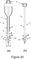
- a third embodiment of the drill assembly (3) is shown, in this embodiment there is a tube plug (67) attached to, or formed as part of, the central shaft (12) of the drill (11).
- the tube plug (67) is dimensioned to sit within the delivery tube (41) whilst sealing the end of the delivery tube (41)when required.
- the tube plug (67) is shown as including a sealing portion (68) and a tapered portion (69).
- the sealing portion (68) being a cylindrical portion of the tube plug (67) that has a cylindrical portion outside diameter ( cpod ) less than di (the inside diameter of the delivery tube (41)) but sufficiently close to di (the inside diameter of the delivery tube (41)) to prevent any detrimental amount of ground material or aggregate from passing along the delivery tube (41) during the insertion of the drill assembly (3) into the ground.
- a detrimental amount is the amount sufficient to affect the compaction, contaminate the aggregate or otherwise detrimentally affect the operation of the drill assembly (3).
- the tapered portion (69) is a frusto conical portion of the tube plug (67) that is located closest to the drill flight (13).
- the minimum diameter of the tapered portion (69) is ⁇ (the outside diameter of the central shaft (12)).
- this sealing ring could be an o-ring, a flexible ring, a bushing of known type or a combination of these.
- FIG 14 One preferred method of using the third embodiment is shown in Figure 14 .
- the tube plug (67) has the tapered portion (69) extending beyond the outlet terminal end (43) as the drill assembly (3) is inserted, this is optional but it is believed to assist the insertion of the delivery tube (41) into the hole made by the drill (11).
- the method is similar to that used for the second embodiment of the drill assembly (3), but, rather than dislodging a tube cap (46) (see Figure 8 ) at a required depth to allow the additional material (33) in the hopper (40) to flow through the delivery tube (41); the drill (11) is moved in relation to the delivery tube (41) which moves the tube plug (67).
- Step (x) The drill (11) is rotated in the direction of arrow C as the drill assembly (3) is pushed into the ground in the direction of arrow I.
- the tube plug (67) is located within the delivery tube (41) acting to seal the outlet terminal end (43).
- Step (xi) The drill (11) reaches full depth and the drill (11) is stopped.
- the drill (11) is moved in relation to the delivery tube (41), this opens the outlet terminal end (43) by moving the tube plug (67) out of the delivery tube (41).
- the displacement unit (10) is engaged, if it has not been engaged by the movement of the drill (11) in relation to the delivery tube (41). With the outlet terminal end (43) now open the additional material (33) is free to pass through the outlet terminal end (43) of the delivery tube (41).
- Step (xii) The drill (11) is now rotated in the direction of arrow AC (the opposite direction to step (x).
- the interaction between the guides (23) in the guide channels (22) causes the drill (11) to vibrate/oscillate as it is rotated in the opposite direction, and this compacts, and/or modifies the properties of the material (32) around the drill flight (13).
- the rotation of the drill (11) also moves material (32) radially outwards. This compaction and/or displacement sometimes causes the ground surface to distort or sink, this can require additional material (33) to be added.
- Step (xiii) The drill (11) is rotated in the reverse direction, in the direction of arrow AC, and withdrawn from the ground (in the direction of arrow E) at a rate which compacts the material and incorporates any additional material (33) supplied from the hopper (40) through the delivery tube (41) to the required level.
- This operation forming a compacted zone of material (32) that starts at or below the maximum drill (11) depth and extends to the surface, or a point between the lower compacted zone and the surface.
- the amount of compaction can be varied by adjusting the rotational speed of the drill (11), the torque of the drill (11), the withdrawal rate and the amount/type of additional material (33) added for example.
- the additional material (33) may be added to increase the density of the compacted zone even if the surface does not distort or sink.
- a tube cap (46) and a tube plug (67) can both be present in a single drill assembly (3) configuration, though this is not shown.
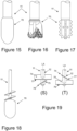
- FIGs 15 to 19 show alternative drill tips/bits (70) that may be used instead of, or in combination with (see Fig 18 ), a drill flight (13) (shown in Fig. 18 ). These are examples only and any drill bit/tip (70) normally used for this sort of work can be used. Noting that the drill flight (13) will normally co-terminate at the terminal end (first end (14)) of the drill (11) that enters the ground first, but if a drill tip/bit (70) is present then it may terminate at or on the drill tip/bit (70).
- Figure 18 shows a combined drill bit/tip with both a drill flight (13) and a bulb end.
- FIG 19 shows two views of a bladed drill tip/bit where (T) is view (S) rotated 90° about the longitudinal axis (LA), in this variant there are two angled trans-axial flat plates (74,75) attached to the central shaft (12).
- the flat plates (74,75) are spaced apart along the length of the drill (11), and extend away from both sides of the central shaft (12).
- each flat plate (74,75) may be twisted so that the angle of each flat plate (74,75) on each side of the central shaft (12) is such that the lowermost edge (76,77) of each said flat plates (74,75) is a leading edge during insertion of the drill (11).
- the lowermost edge (76,77) of said flat plates (74,75) is the edge of the flat plate (74,75) in question that enters the ground first when the drill (11) is in use.
- the drill (11) includes an alpha section (80).
- the alpha section (80) in the variant shown is a portion of the drill (11) located within the section of the drill (11) that includes the drill flight (13).
- the alpha section (80) is a cylinder with a diameter (d ⁇ ) greater than ⁇ (the diameter of the central shaft (12)) but less than D (the maximum diameter of the drill flight (13).
- the alpha section (80) may be elliptical or oval in cross section, with the longest axis having a length greater than ⁇ (the diameter of the central shaft (12)).
- a drill assembly (3) that includes a drill (11) with the alpha section (80) creates a larger hole in the ground than one without this expanded section.
- This larger hole can reduce the power required to insert a drill assembly (3) that includes a delivery tube (41) as the hole can be sized closer to the delivery tube's (41) diameter (do).
- the alpha section (80) is not located within the portion of the drill (11) that includes the drill flight (13).
Landscapes
- Engineering & Computer Science (AREA)
- Life Sciences & Earth Sciences (AREA)
- Mining & Mineral Resources (AREA)
- Structural Engineering (AREA)
- General Life Sciences & Earth Sciences (AREA)
- Environmental & Geological Engineering (AREA)
- General Engineering & Computer Science (AREA)
- Paleontology (AREA)
- Civil Engineering (AREA)
- Geology (AREA)
- Soil Sciences (AREA)
- Agronomy & Crop Science (AREA)
- Physics & Mathematics (AREA)
- Fluid Mechanics (AREA)
- Geochemistry & Mineralogy (AREA)
- Mechanical Engineering (AREA)
- Earth Drilling (AREA)
- Coloring Foods And Improving Nutritive Qualities (AREA)
Claims (16)
- Ensemble de forage (3) qui ne comprend qu'un foret (11) et une unité de déplacement (10), caractérisé en ce que :- l'unité de déplacement (10) comprend une unité de guidage (23) et une unité de canal (30), l'unité de canal (30) comprenant un canal de guidage (22), et ladite unité de guidage (23) comprend un ou plusieurs guides (23) adaptés pour entrer en prise avec ledit canal de guidage (22), ledit canal de guidage (22) étant un canal circonférentiel qui suit une trajectoire ondulatoire ou semblable à une ondulation ;- le foret (11) comprend un trépan (70) et/ou une goujure de foret (13) fixée à une tige centrale (12), dans lequel le trépan (70) et/ou la goujure de foret (13) se terminent conjointement à une première extrémité terminale du foret (11) ;- ladite première extrémité terminale est l'extrémité terminale du foret (11) qui est conçue pour entrer dans le sol en premier ;- la tige centrale (12) est un élément allongé mince qui s'étend entre les extrémités terminales séparées longitudinalement du foret (11) ; et- le foret (11) est fixé de manière amovible ou permanente à l'unité de déplacement (10) de sorte que lorsque le foret (11) est en prise avec l'unité de déplacement (10), l'interaction entre les guides (23) et le canal de guidage (22) amènent le foret à osciller le long de son axe longitudinal.
- Ensemble de forage selon la revendication 1, dans lequel ledit foret (11) est une tarière.
- Ensemble de forage selon la revendication 1 ou la revendication 2, ledit ensemble de forage (3) comprenant un tube d'évacuation (41) qui entoure circonférentiellement une partie de la tige centrale (12).
- Ensemble de forage selon la revendication 3, dans lequel un diamètre extérieur maximum de la goujure de foret (13) et/ou du trépan (70) (D) est supérieur à un diamètre extérieur du tube d'évacuation (41) (do).
- Ensemble de forage selon la revendication 3 ou la revendication 4, dans lequel le tube d'évacuation (41) ne tourne pas avec le foret (11).
- Ensemble de forage selon l'une quelconque des revendications 3 à 5, l'ensemble de forage (3) comprenant une trémie (40) qui est conçue pour contenir un matériau supplémentaire, de sorte que ladite trémie (40) est reliée au tube d'évacuation (41) de manière à permettre au matériau supplémentaire de s'écouler de la trémie (40) et à travers le tube d'évacuation (41) lorsque cela est nécessaire.
- Ensemble de forage selon l'une quelconque des revendications 3 à 6, dans lequel le tube d'évacuation (41) est relié à la tige centrale (12) par au moins une fixation tige-tube (63) de sorte que le tube d'évacuation (41) est conçu pour tourner avec la tige centrale (12).
- Ensemble de forage selon la revendication 7, dans lequel l'au moins une fixation tige-tube (63) est un raccord rigide entre le tube d'évacuation (41) et la tige centrale (12) de sorte que, lors de l'utilisation, tout mouvement rotatif et/ou longitudinal de la tige centrale (12) est transmis au tube d'évacuation (41).
- Ensemble de forage selon l'une quelconque des revendications 3 à 8, dans lequel le tube d'évacuation (41) comprend un capuchon de tube (46), le capuchon de tube (46) bloque partiellement ou complètement une extrémité terminale de sortie dudit tube d'évacuation (41), de sorte que ledit capuchon de tube (46) est conçu pour se détacher du tube d'évacuation (41) lorsque cela est nécessaire.
- Ensemble de forage selon l'une quelconque des revendications 3 à 9, dans lequel le foret (11) comprend une goujure de tige (60) qui s'étend le long d'une partie de la longueur de la tige centrale (12) qui se trouve au moins partiellement à l'intérieur du tube d'évacuation (41).
- Ensemble de forage selon l'une quelconque des revendications 3 à 10, dans lequel le foret (11) comprend un bouchon de tube (67) qui est fixé à la tige centrale (12) ou fait partie de cette dernière, ledit bouchon de tube (67), dans une première position, se situe à l'intérieur du tube d'évacuation (41) et s'étend radialement de la tige centrale (12) vers le tube d'évacuation (41), de sorte que ledit bouchon de tube (67) est dimensionné pour fermer hermétiquement ou bloquer efficacement le tube d'évacuation (41) dans ladite première position.
- Ensemble de forage selon l'une quelconque des revendications précédentes, dans lequel le canal de guidage (22) est constitué d'une pluralité d'ondes partielles ou d'une superposition de formes d'onde.
- Ensemble de foret selon l'une quelconque des revendications précédentes, dans lequel le canal de guidage (22) a une distance crête à creux comprise entre 1 mm et 400 mm.
- Ensemble de forage selon l'une quelconque des revendications précédentes, dans lequel il y a soit un trépan (70) soit une goujure de foret (13), mais pas les deux.
- Ensemble de foret selon la revendication 14, dans lequel il y a une goujure de foret (13), et le foret (11) comprend une section alpha qui est une partie du foret avec une dimension en coupe transversale maximale supérieure à une dimension en coupe transversale maximale de la tige centrale (12).
- Procédé d'utilisation d'un ensemble de forage selon l'une quelconque des revendications précédentes comprenant les étapes suivantes :(i) insertion du foret (11) dans une surface du sol ;(ii) poursuite du forage jusqu'à ce qu'une profondeur requise soit atteinte, puis insertion du dispositif de déplacement (10) pour commencer à compacter/consolider le matériau du sol environnant ;(iii) retrait du foret (11) avec le dispositif de déplacement (10) en marche.
Applications Claiming Priority (2)
| Application Number | Priority Date | Filing Date | Title |
|---|---|---|---|
| NZ72198116 | 2016-07-08 | ||
| PCT/IB2017/054090 WO2018007983A1 (fr) | 2016-07-08 | 2017-07-07 | Dispositif de déplacement et/ou de compactage |
Publications (3)
| Publication Number | Publication Date |
|---|---|
| EP3482005A1 EP3482005A1 (fr) | 2019-05-15 |
| EP3482005A4 EP3482005A4 (fr) | 2020-03-18 |
| EP3482005B1 true EP3482005B1 (fr) | 2023-08-16 |
Family
ID=60912421
Family Applications (1)
| Application Number | Title | Priority Date | Filing Date |
|---|---|---|---|
| EP17823745.9A Active EP3482005B1 (fr) | 2016-07-08 | 2017-07-07 | Dispositif de déplacement et/ou de compactage |
Country Status (7)
| Country | Link |
|---|---|
| US (1) | US11047102B2 (fr) |
| EP (1) | EP3482005B1 (fr) |
| CA (1) | CA3027674C (fr) |
| MX (1) | MX2018015384A (fr) |
| MY (1) | MY195875A (fr) |
| SG (1) | SG11201810546PA (fr) |
| WO (1) | WO2018007983A1 (fr) |
Families Citing this family (1)
| Publication number | Priority date | Publication date | Assignee | Title |
|---|---|---|---|---|
| AU2022339936A1 (en) * | 2021-08-31 | 2024-03-21 | Geopier Foundation Company, Inc. | A system and method for installing an aggregate pier |
Family Cites Families (10)
| Publication number | Priority date | Publication date | Assignee | Title |
|---|---|---|---|---|
| US3864923A (en) * | 1973-09-18 | 1975-02-11 | Lee A Turzillo | Impacted casing method for installing anchor piles or tiebacks in situ |
| US4046205A (en) * | 1974-04-29 | 1977-09-06 | Kabushiki Kaisha Takechi Koumusho | Earth auger and method for driving piles and the like by means of said earth auger |
| US4637758A (en) * | 1982-03-11 | 1987-01-20 | Kabushiki Kaisha Komatsu Seisakusho | Method of driving hollow piles into the ground |
| FR2626025B1 (fr) * | 1988-01-14 | 1990-07-13 | Minaberry Michel | Dispositif pour le forage des sols |
| JP2000054363A (ja) * | 1998-08-10 | 2000-02-22 | Kumagai Gumi Co Ltd | 地盤改良装置 |
| US7226246B2 (en) * | 2000-06-15 | 2007-06-05 | Geotechnical Reinforcement, Inc. | Apparatus and method for building support piers from one or successive lifts formed in a soil matrix |
| US8152415B2 (en) * | 2000-06-15 | 2012-04-10 | Geopier Foundation Company, Inc. | Method and apparatus for building support piers from one or more successive lifts formed in a soil matrix |
| KR100668504B1 (ko) * | 2006-03-15 | 2007-01-12 | (주)수림건설 | 연약지반을 개량하기 위한 내부스크루와 유압실린더 다짐식 무진동 무소음 시공장비 및 그의 공법 |
| AU2012241026B2 (en) * | 2011-04-04 | 2014-09-11 | Jaron Lyell Mcmillan | Machine and method for forming an in ground granular column |
| EA029087B1 (ru) * | 2012-12-10 | 2018-02-28 | Джарон Лайелл Макмиллан | Усовершенствованный бур для изготовления щебеночных свай |
-
2017
- 2017-07-07 SG SG11201810546PA patent/SG11201810546PA/en unknown
- 2017-07-07 US US16/309,469 patent/US11047102B2/en active Active
- 2017-07-07 EP EP17823745.9A patent/EP3482005B1/fr active Active
- 2017-07-07 MX MX2018015384A patent/MX2018015384A/es unknown
- 2017-07-07 WO PCT/IB2017/054090 patent/WO2018007983A1/fr unknown
- 2017-07-07 CA CA3027674A patent/CA3027674C/fr active Active
- 2017-07-07 MY MYPI2018002373A patent/MY195875A/en unknown
Also Published As
| Publication number | Publication date |
|---|---|
| CA3027674A1 (fr) | 2018-01-11 |
| US20190316312A1 (en) | 2019-10-17 |
| US11047102B2 (en) | 2021-06-29 |
| MY195875A (en) | 2023-02-26 |
| EP3482005A4 (fr) | 2020-03-18 |
| EP3482005A1 (fr) | 2019-05-15 |
| CA3027674C (fr) | 2021-01-05 |
| MX2018015384A (es) | 2019-04-29 |
| WO2018007983A1 (fr) | 2018-01-11 |
| SG11201810546PA (en) | 2018-12-28 |
Similar Documents
| Publication | Publication Date | Title |
|---|---|---|
| EP3464734B1 (fr) | Dispositif d'installation de pieu de fondation | |
| AU2022201161B2 (en) | Lateral drilling method | |
| AU2016332745C1 (en) | Percussion device | |
| EP2758625B1 (fr) | Dispositif de génération d'ondes, système de tubage, et procédé de cimentation d'un tubage dans un trou de forage | |
| US4071097A (en) | Process and apparatus for supersonic drilling in underground rocky strata | |
| CA3011247A1 (fr) | Ensemble d'empilement de force pour utilisation avec un systeme d'excavation souterraine | |
| EA029087B1 (ru) | Усовершенствованный бур для изготовления щебеночных свай | |
| US4548281A (en) | Apparatus and method for installing well casings in the ground employing resonant sonic energy in conjunction with hydraulic pulsating jet action | |
| EP3482005B1 (fr) | Dispositif de déplacement et/ou de compactage | |
| EP2694744B1 (fr) | Machine et procédé pour former une colonne granulaire souterraine | |
| US20170370067A1 (en) | Methods and devices for improving the subsoil | |
| US3211243A (en) | Sonic drilling by rotating the tool | |
| KR970009947A (ko) | 보링지그 및 보어홀에 파일을 만들기 위한 방법 | |
| AU2020255345B2 (en) | No vibration stone column drill | |
| GB2455303A (en) | Method and apparatus for forming a cast in situ screw pile | |
| RU2009303C1 (ru) | Способ ударно-вращательного бурения скважин и устройство для его осуществления | |
| JP2004197468A (ja) | 地盤改良工法 | |
| NZ592051A (en) | Ground column machine with inner screw and outer tubular screw with primarily vertical compaction |
Legal Events
| Date | Code | Title | Description |
|---|---|---|---|
| STAA | Information on the status of an ep patent application or granted ep patent |
Free format text: STATUS: THE INTERNATIONAL PUBLICATION HAS BEEN MADE |
|
| PUAI | Public reference made under article 153(3) epc to a published international application that has entered the european phase |
Free format text: ORIGINAL CODE: 0009012 |
|
| STAA | Information on the status of an ep patent application or granted ep patent |
Free format text: STATUS: REQUEST FOR EXAMINATION WAS MADE |
|
| 17P | Request for examination filed |
Effective date: 20190103 |
|
| AK | Designated contracting states |
Kind code of ref document: A1 Designated state(s): AL AT BE BG CH CY CZ DE DK EE ES FI FR GB GR HR HU IE IS IT LI LT LU LV MC MK MT NL NO PL PT RO RS SE SI SK SM TR |
|
| AX | Request for extension of the european patent |
Extension state: BA ME |
|
| DAV | Request for validation of the european patent (deleted) | ||
| DAX | Request for extension of the european patent (deleted) | ||
| A4 | Supplementary search report drawn up and despatched |
Effective date: 20200217 |
|
| RIC1 | Information provided on ipc code assigned before grant |
Ipc: E02D 3/12 20060101ALI20200211BHEP Ipc: E21B 7/24 20060101ALI20200211BHEP Ipc: E02D 3/08 20060101AFI20200211BHEP Ipc: E02D 3/10 20060101ALI20200211BHEP |
|
| STAA | Information on the status of an ep patent application or granted ep patent |
Free format text: STATUS: EXAMINATION IS IN PROGRESS |
|
| 17Q | First examination report despatched |
Effective date: 20220223 |
|
| GRAP | Despatch of communication of intention to grant a patent |
Free format text: ORIGINAL CODE: EPIDOSNIGR1 |
|
| STAA | Information on the status of an ep patent application or granted ep patent |
Free format text: STATUS: GRANT OF PATENT IS INTENDED |
|
| RIC1 | Information provided on ipc code assigned before grant |
Ipc: E02D 3/10 20060101ALI20230504BHEP Ipc: E02D 3/08 20060101AFI20230504BHEP |
|
| INTG | Intention to grant announced |
Effective date: 20230524 |
|
| P01 | Opt-out of the competence of the unified patent court (upc) registered |
Effective date: 20230518 |
|
| GRAS | Grant fee paid |
Free format text: ORIGINAL CODE: EPIDOSNIGR3 |
|
| GRAA | (expected) grant |
Free format text: ORIGINAL CODE: 0009210 |
|
| STAA | Information on the status of an ep patent application or granted ep patent |
Free format text: STATUS: THE PATENT HAS BEEN GRANTED |
|
| AK | Designated contracting states |
Kind code of ref document: B1 Designated state(s): AL AT BE BG CH CY CZ DE DK EE ES FI FR GB GR HR HU IE IS IT LI LT LU LV MC MK MT NL NO PL PT RO RS SE SI SK SM TR |
|
| REG | Reference to a national code |
Ref country code: GB Ref legal event code: FG4D |
|
| REG | Reference to a national code |
Ref country code: CH Ref legal event code: EP Ref country code: DE Ref legal event code: R096 Ref document number: 602017072874 Country of ref document: DE |
|
| REG | Reference to a national code |
Ref country code: IE Ref legal event code: FG4D |
|
| REG | Reference to a national code |
Ref country code: LT Ref legal event code: MG9D |
|
| REG | Reference to a national code |
Ref country code: NL Ref legal event code: MP Effective date: 20230816 |
|
| REG | Reference to a national code |
Ref country code: AT Ref legal event code: MK05 Ref document number: 1600174 Country of ref document: AT Kind code of ref document: T Effective date: 20230816 |
|
| PG25 | Lapsed in a contracting state [announced via postgrant information from national office to epo] |
Ref country code: GR Free format text: LAPSE BECAUSE OF FAILURE TO SUBMIT A TRANSLATION OF THE DESCRIPTION OR TO PAY THE FEE WITHIN THE PRESCRIBED TIME-LIMIT Effective date: 20231117 |
|
| PG25 | Lapsed in a contracting state [announced via postgrant information from national office to epo] |
Ref country code: IS Free format text: LAPSE BECAUSE OF FAILURE TO SUBMIT A TRANSLATION OF THE DESCRIPTION OR TO PAY THE FEE WITHIN THE PRESCRIBED TIME-LIMIT Effective date: 20231216 |
|
| PG25 | Lapsed in a contracting state [announced via postgrant information from national office to epo] |
Ref country code: SE Free format text: LAPSE BECAUSE OF FAILURE TO SUBMIT A TRANSLATION OF THE DESCRIPTION OR TO PAY THE FEE WITHIN THE PRESCRIBED TIME-LIMIT Effective date: 20230816 Ref country code: RS Free format text: LAPSE BECAUSE OF FAILURE TO SUBMIT A TRANSLATION OF THE DESCRIPTION OR TO PAY THE FEE WITHIN THE PRESCRIBED TIME-LIMIT Effective date: 20230816 Ref country code: PT Free format text: LAPSE BECAUSE OF FAILURE TO SUBMIT A TRANSLATION OF THE DESCRIPTION OR TO PAY THE FEE WITHIN THE PRESCRIBED TIME-LIMIT Effective date: 20231218 Ref country code: NO Free format text: LAPSE BECAUSE OF FAILURE TO SUBMIT A TRANSLATION OF THE DESCRIPTION OR TO PAY THE FEE WITHIN THE PRESCRIBED TIME-LIMIT Effective date: 20231116 Ref country code: NL Free format text: LAPSE BECAUSE OF FAILURE TO SUBMIT A TRANSLATION OF THE DESCRIPTION OR TO PAY THE FEE WITHIN THE PRESCRIBED TIME-LIMIT Effective date: 20230816 Ref country code: LV Free format text: LAPSE BECAUSE OF FAILURE TO SUBMIT A TRANSLATION OF THE DESCRIPTION OR TO PAY THE FEE WITHIN THE PRESCRIBED TIME-LIMIT Effective date: 20230816 Ref country code: LT Free format text: LAPSE BECAUSE OF FAILURE TO SUBMIT A TRANSLATION OF THE DESCRIPTION OR TO PAY THE FEE WITHIN THE PRESCRIBED TIME-LIMIT Effective date: 20230816 Ref country code: IS Free format text: LAPSE BECAUSE OF FAILURE TO SUBMIT A TRANSLATION OF THE DESCRIPTION OR TO PAY THE FEE WITHIN THE PRESCRIBED TIME-LIMIT Effective date: 20231216 Ref country code: HR Free format text: LAPSE BECAUSE OF FAILURE TO SUBMIT A TRANSLATION OF THE DESCRIPTION OR TO PAY THE FEE WITHIN THE PRESCRIBED TIME-LIMIT Effective date: 20230816 Ref country code: GR Free format text: LAPSE BECAUSE OF FAILURE TO SUBMIT A TRANSLATION OF THE DESCRIPTION OR TO PAY THE FEE WITHIN THE PRESCRIBED TIME-LIMIT Effective date: 20231117 Ref country code: FI Free format text: LAPSE BECAUSE OF FAILURE TO SUBMIT A TRANSLATION OF THE DESCRIPTION OR TO PAY THE FEE WITHIN THE PRESCRIBED TIME-LIMIT Effective date: 20230816 Ref country code: AT Free format text: LAPSE BECAUSE OF FAILURE TO SUBMIT A TRANSLATION OF THE DESCRIPTION OR TO PAY THE FEE WITHIN THE PRESCRIBED TIME-LIMIT Effective date: 20230816 |
|
| PG25 | Lapsed in a contracting state [announced via postgrant information from national office to epo] |
Ref country code: PL Free format text: LAPSE BECAUSE OF FAILURE TO SUBMIT A TRANSLATION OF THE DESCRIPTION OR TO PAY THE FEE WITHIN THE PRESCRIBED TIME-LIMIT Effective date: 20230816 |
|
| PG25 | Lapsed in a contracting state [announced via postgrant information from national office to epo] |
Ref country code: ES Free format text: LAPSE BECAUSE OF FAILURE TO SUBMIT A TRANSLATION OF THE DESCRIPTION OR TO PAY THE FEE WITHIN THE PRESCRIBED TIME-LIMIT Effective date: 20230816 |
|
| PG25 | Lapsed in a contracting state [announced via postgrant information from national office to epo] |
Ref country code: SM Free format text: LAPSE BECAUSE OF FAILURE TO SUBMIT A TRANSLATION OF THE DESCRIPTION OR TO PAY THE FEE WITHIN THE PRESCRIBED TIME-LIMIT Effective date: 20230816 Ref country code: RO Free format text: LAPSE BECAUSE OF FAILURE TO SUBMIT A TRANSLATION OF THE DESCRIPTION OR TO PAY THE FEE WITHIN THE PRESCRIBED TIME-LIMIT Effective date: 20230816 Ref country code: ES Free format text: LAPSE BECAUSE OF FAILURE TO SUBMIT A TRANSLATION OF THE DESCRIPTION OR TO PAY THE FEE WITHIN THE PRESCRIBED TIME-LIMIT Effective date: 20230816 Ref country code: EE Free format text: LAPSE BECAUSE OF FAILURE TO SUBMIT A TRANSLATION OF THE DESCRIPTION OR TO PAY THE FEE WITHIN THE PRESCRIBED TIME-LIMIT Effective date: 20230816 Ref country code: DK Free format text: LAPSE BECAUSE OF FAILURE TO SUBMIT A TRANSLATION OF THE DESCRIPTION OR TO PAY THE FEE WITHIN THE PRESCRIBED TIME-LIMIT Effective date: 20230816 Ref country code: CZ Free format text: LAPSE BECAUSE OF FAILURE TO SUBMIT A TRANSLATION OF THE DESCRIPTION OR TO PAY THE FEE WITHIN THE PRESCRIBED TIME-LIMIT Effective date: 20230816 Ref country code: SK Free format text: LAPSE BECAUSE OF FAILURE TO SUBMIT A TRANSLATION OF THE DESCRIPTION OR TO PAY THE FEE WITHIN THE PRESCRIBED TIME-LIMIT Effective date: 20230816 |