EP3481716B1 - Hybrid boat - Google Patents
Hybrid boat Download PDFInfo
- Publication number
- EP3481716B1 EP3481716B1 EP17754481.4A EP17754481A EP3481716B1 EP 3481716 B1 EP3481716 B1 EP 3481716B1 EP 17754481 A EP17754481 A EP 17754481A EP 3481716 B1 EP3481716 B1 EP 3481716B1
- Authority
- EP
- European Patent Office
- Prior art keywords
- electric motor
- internal combustion
- combustion engine
- propeller
- inlet
- Prior art date
- Legal status (The legal status is an assumption and is not a legal conclusion. Google has not performed a legal analysis and makes no representation as to the accuracy of the status listed.)
- Active
Links
Images

Classifications
-
- B—PERFORMING OPERATIONS; TRANSPORTING
- B63—SHIPS OR OTHER WATERBORNE VESSELS; RELATED EQUIPMENT
- B63H—MARINE PROPULSION OR STEERING
- B63H23/00—Transmitting power from propulsion power plant to propulsive elements
- B63H23/02—Transmitting power from propulsion power plant to propulsive elements with mechanical gearing
- B63H23/10—Transmitting power from propulsion power plant to propulsive elements with mechanical gearing for transmitting drive from more than one propulsion power unit
-
- B—PERFORMING OPERATIONS; TRANSPORTING
- B63—SHIPS OR OTHER WATERBORNE VESSELS; RELATED EQUIPMENT
- B63H—MARINE PROPULSION OR STEERING
- B63H21/00—Use of propulsion power plant or units on vessels
- B63H21/20—Use of propulsion power plant or units on vessels the vessels being powered by combinations of different types of propulsion units
-
- B—PERFORMING OPERATIONS; TRANSPORTING
- B63—SHIPS OR OTHER WATERBORNE VESSELS; RELATED EQUIPMENT
- B63H—MARINE PROPULSION OR STEERING
- B63H23/00—Transmitting power from propulsion power plant to propulsive elements
- B63H23/30—Transmitting power from propulsion power plant to propulsive elements characterised by use of clutches
-
- B—PERFORMING OPERATIONS; TRANSPORTING
- B63—SHIPS OR OTHER WATERBORNE VESSELS; RELATED EQUIPMENT
- B63H—MARINE PROPULSION OR STEERING
- B63H21/00—Use of propulsion power plant or units on vessels
- B63H21/20—Use of propulsion power plant or units on vessels the vessels being powered by combinations of different types of propulsion units
- B63H2021/202—Use of propulsion power plant or units on vessels the vessels being powered by combinations of different types of propulsion units of hybrid electric type
- B63H2021/205—Use of propulsion power plant or units on vessels the vessels being powered by combinations of different types of propulsion units of hybrid electric type the second power unit being of the internal combustion engine type, or the like, e.g. a Diesel engine
-
- Y—GENERAL TAGGING OF NEW TECHNOLOGICAL DEVELOPMENTS; GENERAL TAGGING OF CROSS-SECTIONAL TECHNOLOGIES SPANNING OVER SEVERAL SECTIONS OF THE IPC; TECHNICAL SUBJECTS COVERED BY FORMER USPC CROSS-REFERENCE ART COLLECTIONS [XRACs] AND DIGESTS
- Y02—TECHNOLOGIES OR APPLICATIONS FOR MITIGATION OR ADAPTATION AGAINST CLIMATE CHANGE
- Y02T—CLIMATE CHANGE MITIGATION TECHNOLOGIES RELATED TO TRANSPORTATION
- Y02T70/00—Maritime or waterways transport
- Y02T70/50—Measures to reduce greenhouse gas emissions related to the propulsion system
- Y02T70/5218—Less carbon-intensive fuels, e.g. natural gas, biofuels
- Y02T70/5236—Renewable or hybrid-electric solutions
Definitions
- the invention relates to the field of hybrid boats, namely boats having both an electric drive and an internal combustion engine.
- series hybrid drives are largely used, namely hybrid drives in which the drive shaft of the internal combustion engine is exclusively driven by an electric motor, which, in turn, is powered by a battery pack or by en electric generator, which is caused to rotate by an internal combustion engine.
- a parallel hybrid drive is preferably used, because of the fact that the sole internal combustion engine ensures a better efficiency than the series drive, due to the lack of electric energy conversion losses.
- the electric motor is on-axis connected to the drive shaft between the internal combustion engine and the propeller. This also implies that, when the electric motor is deactivated, the inertia of the drive shaft is increased by the additional weight of the electric windings of the rotor.
- GB2532731A corresponds to the preamble of claim 1 and discloses a hybrid propulsion system comprising an internal combustion engine and a gear box, having an input shaft connectable to the engine and an output shaft to drive a propeller.
- An electric motor/generator is releasably connectable to the input shaft of the gear box via a clutch.
- the internal combustion engine may act as the major propulsion means and may be supplemented by the electric motor.
- the object of the invention is to provide an efficient electric drive, which ensures a low total inertia.
- the idea on which the invention is based is that of dividing the drive shaft, from the internal combustion engine to the propeller, into two parts and to interpose a transfer box, which is connected to the electric motor.
- the transfer box allows to connect, now, the electric motor, now the second portion of the drive shaft - connected, in turn, to the output shaft of the internal combustion engine -, now both the electric motor and the internal combustion engine to a propeller or impeller of a pump-jet.
- second component does not imply the presence of a "first” component.
- first component does not imply the presence of a "first” component.
- a boat B comprises an internal combustion engine, preferably a Diesel cycle engine, which is provided with a reversing device so as to enable at least one condition of forward movement and one of reverse movement.
- an internal combustion engine preferably a Diesel cycle engine
- a first shaft X1 is connected between an outlet of said reversing device of the internal combustion engine and a first inlet IN1 of the transfer box TB, whereas an electric motor EM has its own rotor connected to a second inlet IN2 of the transfer box TB.
- a second shaft X2 is connected between said single outlet OUT and a propeller or impeller of a pump-jet on the outside of the hull. Therefore, the second shaft X2 goes through the hull in a known manner.
- the transfer box TB comprises two transmission shafts A1 and A2, which are parallel to each other.
- the first one, A1 has an end defining said first inlet IN1 and a second end, opposite the first one, defining said single outlet OUT.
- the first transmission shaft A1 is formed in two parts A11 and A12. The first part defines said first inlet IN1 and the second part defines said single outlet OUT.
- the two parts A11 and A12 are reversibly connectable to each other by means of a first dog clutch DC1, which can axially slide on, and is integral in rotation with, said first part A11.
- first toothed wheel G1 On the second part A12 there is fitted a first toothed wheel G1, which is reversibly connectable to said second part A12 by means of a second dog clutch DC2, which can axially slide on, and is integral in rotation with, said second part A12.
- Said first toothed wheel operatively engages a second toothed wheel G2 in one single piece with said second transmission shaft A2.
- Figures 2 and 3 are identical to one another with the sole exception of the Bout bearing associated with the second part A12 of the first transmission shaft A1.
- a thrust bearing is disclosed, preferably comprising two rings of opposite conical rollers.
- the second inlet IN2 is preferably located on the same side of the first inlet IN1. In other words, both inlets IN1 and IN2 are facing the bow.
- a lid which can be removed in order to connect, preferably by means of a clutch or dog clutch, a user, for example for the operation of winches and other on-board devices.
- the first dog clutch is engaged making the first and second parts A11 and A12 rotate integrally with each other to transfer torque from the internal combustion engine E to the propeller (P).
- the second dog clutch is disengaged, so that a rotor of the electric motor is disconnected from drive shaft line.
- the first dog clutch DC1 is disengaged and the second connector DC2 is engaged so that the electric motor can drive in rotation the propeller P, while the first shaft X1 is disconnected from the drive shaft line.
- both dog clutches are engaged, so that both the internal combustion engine and the electric motor are connected to the drive shaft line.
- the electric motor can operate as electric motor complementing the internal combustion engine, especially in planing-start conditions, or it can operate as electric generator to store electric energy in a specific battery pack, which is not shown.
- the aforesaid operating configurations can be managed by means of suitable electric or hydraulic or electric-hydraulic actuators, which are designed to operate said clutches.
- This configuration allows to connect the transfer downstream of the reversing device included in the internal combustion engine.
- reversing devices besides enabling a forward movement, a reverse movement and a neutral condition, also provide a given reduction of the revolutions, with a significant increase in the torque delivered.
- the transfer box according to the invention as it comprises dog clutches, can more easily support high torques and, hence, it allows manufacturers to keep the reduction gears with a lower inertia of the axis line upstream, especially in electric drive conditions.
- the transfer can be inserted on the axis line regardless of the type of internal combustion engine and reducer used, as it can be equipped with its own thrust bearing, which is capable of supporting the thrust of the propeller both during the forward movement and during the reverse movement.
Landscapes
- Chemical & Material Sciences (AREA)
- Engineering & Computer Science (AREA)
- Combustion & Propulsion (AREA)
- Mechanical Engineering (AREA)
- Ocean & Marine Engineering (AREA)
- Hybrid Electric Vehicles (AREA)
- Hydrogen, Water And Hydrids (AREA)
Description
- The invention relates to the field of hybrid boats, namely boats having both an electric drive and an internal combustion engine.
- In the naval field, series hybrid drives are largely used, namely hybrid drives in which the drive shaft of the internal combustion engine is exclusively driven by an electric motor, which, in turn, is powered by a battery pack or by en electric generator, which is caused to rotate by an internal combustion engine.
- When dealing with leisure boats, a parallel hybrid drive is preferably used, because of the fact that the sole internal combustion engine ensures a better efficiency than the series drive, due to the lack of electric energy conversion losses.
- According to a known parallel hybrid configuration, the electric motor is on-axis connected to the drive shaft between the internal combustion engine and the propeller. This also implies that, when the electric motor is deactivated, the inertia of the drive shaft is increased by the additional weight of the electric windings of the rotor.
- On the other hand, when the electric motor is active and the internal combustion engine is deactivated, the entire drive shaft, from the propeller to the reversing device, is dragged in rotation by the electric motor.
-
GB2532731A claim 1 and discloses a hybrid propulsion system comprising an internal combustion engine and a gear box, having an input shaft connectable to the engine and an output shaft to drive a propeller. An electric motor/generator is releasably connectable to the input shaft of the gear box via a clutch. The internal combustion engine may act as the major propulsion means and may be supplemented by the electric motor. - The object of the invention is to provide an efficient electric drive, which ensures a low total inertia.
- The idea on which the invention is based is that of dividing the drive shaft, from the internal combustion engine to the propeller, into two parts and to interpose a transfer box, which is connected to the electric motor.
- The transfer box allows to connect, now, the electric motor, now the second portion of the drive shaft - connected, in turn, to the output shaft of the internal combustion engine -, now both the electric motor and the internal combustion engine to a propeller or impeller of a pump-jet.
- According to the invention, there is provided a hybrid boat according to
claim 1. - The claims describe preferred embodiments of the invention, thus forming an integral part of the description.
- Further objects and advantages of the invention will be best understood upon perusal of the following detailed description of an embodiment thereof (and of relative variants) with reference to the accompanying drawings merely showing non-limiting examples, wherein:
-
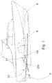
figure 1 shows a boat with a hybrid drive according to the invention, implementing a transfer box; -
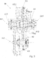
figure 2 shows a longitudinal section of a first preferred variant of the transfer box shown infigure 1 ; -
figure 3 shows a longitudinal section of a second preferred variant of the transfer box shown infigure 1 . - In the figures, the same numbers and the same reference letters indicate the same elements or components.
- For the purposes of the invention, the term "second" component does not imply the presence of a "first" component. As a matter of fact, these terms are only used for greater clarity and should not be interpreted in a limiting manner.
- With reference to
figure 1 , a boat B comprises an internal combustion engine, preferably a Diesel cycle engine, which is provided with a reversing device so as to enable at least one condition of forward movement and one of reverse movement. - A first shaft X1 is connected between an outlet of said reversing device of the internal combustion engine and a first inlet IN1 of the transfer box TB, whereas an electric motor EM has its own rotor connected to a second inlet IN2 of the transfer box TB. A second shaft X2 is connected between said single outlet OUT and a propeller or impeller of a pump-jet on the outside of the hull. Therefore, the second shaft X2 goes through the hull in a known manner. The transfer box TB, according to a preferred aspect of the invention, comprises two transmission shafts A1 and A2, which are parallel to each other. The first one, A1, has an end defining said first inlet IN1 and a second end, opposite the first one, defining said single outlet OUT. The first transmission shaft A1 is formed in two parts A11 and A12. The first part defines said first inlet IN1 and the second part defines said single outlet OUT.
- The two parts A11 and A12 are reversibly connectable to each other by means of a first dog clutch DC1, which can axially slide on, and is integral in rotation with, said first part A11.
- On the second part A12 there is fitted a first toothed wheel G1, which is reversibly connectable to said second part A12 by means of a second dog clutch DC2, which can axially slide on, and is integral in rotation with, said second part A12.
- Said first toothed wheel operatively engages a second toothed wheel G2 in one single piece with said second transmission shaft A2.
-
Figures 2 and3 are identical to one another with the sole exception of the Bout bearing associated with the second part A12 of the first transmission shaft A1. As a matter of fact, infigure 2 it is a ball bearing, whereas infigure 3 a thrust bearing is disclosed, preferably comprising two rings of opposite conical rollers. - The solution of
figure 3 is very advantageous, as it allows to avoid the installation of a similar bearing to support the second shaft X2. - As far as the second transmission shaft A2 of the transfer box is concerned, the second inlet IN2 is preferably located on the same side of the first inlet IN1. In other words, both inlets IN1 and IN2 are facing the bow.
- It is disclosed that the end opposite to the second inlet IN2 of the second transmission shaft A2 is hidden by a lid, which can be removed in order to connect, preferably by means of a clutch or dog clutch, a user, for example for the operation of winches and other on-board devices.
- In this way it is, advantageously, possible to operate said user during "internal combustion engine" navigation and, vice versa, it can be exploited the electric motor to drive the boat in harbour areas or in areas where "internal combustion engine" navigation is forbidden, if necessary disconnecting said user.
- Preferably, in a first operating condition, the first dog clutch is engaged making the first and second parts A11 and A12 rotate integrally with each other to transfer torque from the internal combustion engine E to the propeller (P).
- The second dog clutch is disengaged, so that a rotor of the electric motor is disconnected from drive shaft line. According to a second operating condition, on the contrary, the first dog clutch DC1 is disengaged and the second connector DC2 is engaged so that the electric motor can drive in rotation the propeller P, while the first shaft X1 is disconnected from the drive shaft line.
- According to a third operating condition, both dog clutches are engaged, so that both the internal combustion engine and the electric motor are connected to the drive shaft line. The electric motor can operate as electric motor complementing the internal combustion engine, especially in planing-start conditions, or it can operate as electric generator to store electric energy in a specific battery pack, which is not shown.
- The aforesaid operating configurations can be managed by means of suitable electric or hydraulic or electric-hydraulic actuators, which are designed to operate said clutches.
- This configuration allows to connect the transfer downstream of the reversing device included in the internal combustion engine. As a matter of fact, it is known that reversing devices, besides enabling a forward movement, a reverse movement and a neutral condition, also provide a given reduction of the revolutions, with a significant increase in the torque delivered. Nevertheless, the transfer box according to the invention, as it comprises dog clutches, can more easily support high torques and, hence, it allows manufacturers to keep the reduction gears with a lower inertia of the axis line upstream, especially in electric drive conditions.
- As it can be seen in
figure 1 , if the internal combustion engine E is housed approximately at the centre of the boat, in the longitudinal direction thereof, the electric motor EM is closer to the internal combustion engine E with a better collocation of the weights in a central area of the boat. - Advantageously, the transfer can be inserted on the axis line regardless of the type of internal combustion engine and reducer used, as it can be equipped with its own thrust bearing, which is capable of supporting the thrust of the propeller both during the forward movement and during the reverse movement.
- When reading the description above, a skilled person can carry out the subject-matter of the invention without introducing further manufacturing details. The information contained in the part concerning the state of art only serves the purpose of better understanding the invention and does not represent a declaration of existence of the items described. Furthermore, if not specifically excluded by the detailed description, the information contained in the part concerning the state of art should be considered as an integral part of the invention.
Claims (7)
- Hybrid boat (B) comprising:- an internal combustion engine (E);- a reversing device to allow at least one condition of forward movement and one of reverse movement of the boat;- a propeller or impeller;- transmission means (X1, TB, X2) comprising:+ a transfer box (TB) having a first inlet (IN1), a second inlet (IN2) and a single outlet (OUT),+ an input shaft (X1), and+ an output shaft (X2) interposed between said single outlet (OUT) and said propeller or impeller; and- an electric motor (EM) operatively connected with said second inlet;wherein said transfer box comprises means (DC1, DC2) for selectively connecting said internal combustion engine and/or said electric motor (EM) with said single outlet (OUT), which allows to select the connection of the electric motor or the internal combustion engine or both the electric motor and the internal combustion engine, to said propeller or impeller;wherein said transfer box comprises a first and a second transmission shafts (A1, A2) parallel to each other;characterized in that- the internal combustion engine is provided with said reversing device, so that the transmission means are connected between said reversing device and said propeller or impeller (P), and said input shaft (X1) is interposed between said reversing device and said first inlet (IN1); said first transmission shaft is formed in two parts (A11, A12), wherein a first part (A11) of the two parts defines said first inlet (IN1) and a second part (A12) of the two parts defines said single outlet (OUT), and wherein said first and second parts are reversibly connectable to each other by means of a first dog clutch (DC1) ;the first transmission shaft (A1) having a first end defining said first inlet (IN1) and a second end, opposite the first end, defining said single outlet (OUT);wherein a first toothed wheel (G1) is fitted on said second part (A12); the first toothed wheel (G1) being reversibly connectable to said second part (A12) by means of a second dog clutch (DC2); and wherein said second transmission shaft (A2) comprises a second toothed wheel (G2) that operatively connects with said first toothed wheel (G1).
- Boat according to claim 1, wherein said second transmission shaft (A2) is in one piece.
- Boat according to claim 2, wherein said transfer box (TB) is configured to allow:- a first operating condition, wherein said first dog clutch is engaged so as to make the first and second part (A11, A12) rotate integrally with each other, to transfer torque from the internal combustion engine (E) to said propeller or impeller (P), while said second dog clutch is disengaged, so that a rotor of the electric motor is disconnected from said output shaft (X2);- a second operating condition, wherein said first dog clutch (DC1) is disengaged and said second dog clutch (DC2) is engaged, so that the electric motor can drive in rotation said propeller or impeller (P), while said input shaft (X1) is disconnected from said output shaft (X2);- a third operating condition wherein both said first and second dog clutches are engaged, so that both the internal combustion engine and the electric motor are connected to said output shaft (X2).
- Boat according to claim 3, wherein according to said third operating conditions said electric motor (EM) can operate as electric motor complementing the internal combustion engine (E), or can operate as electric generator to store electric energy in a specific battery pack.
- Boat according to any one of the preceding claims 1 to 4, wherein said first and second inlets are facing the bow.
- Boat according to any one of the preceding claims 1 to 5, wherein said transfer box further integrates a bearing (Bout) associated with said second part (A12) of the first transmission shaft (A1); and wherein said bearing is of the thrust type.
- Boat according to any one of the preceding claims 3 or 4, further comprising processor means configured to control said means (DC1, DC2), said internal combustion engine and said electric motor to produce said first, second and third operating conditions.
Applications Claiming Priority (2)
| Application Number | Priority Date | Filing Date | Title |
|---|---|---|---|
| IT102016000072139A IT201600072139A1 (en) | 2016-07-11 | 2016-07-11 | BOAT WITH HYBRID PROPULSION |
| PCT/IB2017/054180 WO2018011713A1 (en) | 2016-07-11 | 2017-07-11 | Hybrid boat |
Publications (2)
| Publication Number | Publication Date |
|---|---|
| EP3481716A1 EP3481716A1 (en) | 2019-05-15 |
| EP3481716B1 true EP3481716B1 (en) | 2021-09-22 |
Family
ID=57737817
Family Applications (1)
| Application Number | Title | Priority Date | Filing Date |
|---|---|---|---|
| EP17754481.4A Active EP3481716B1 (en) | 2016-07-11 | 2017-07-11 | Hybrid boat |
Country Status (5)
| Country | Link |
|---|---|
| US (1) | US10661875B2 (en) |
| EP (1) | EP3481716B1 (en) |
| CN (1) | CN109661344A (en) |
| IT (1) | IT201600072139A1 (en) |
| WO (1) | WO2018011713A1 (en) |
Families Citing this family (4)
| Publication number | Priority date | Publication date | Assignee | Title |
|---|---|---|---|---|
| IT201600072139A1 (en) * | 2016-07-11 | 2018-01-11 | Fpt Ind Spa | BOAT WITH HYBRID PROPULSION |
| GB2565050B (en) * | 2017-07-27 | 2020-06-17 | Dolphin N2 Ltd | Split cycle engine with peak combustion temperature control |
| IT201900008799A1 (en) | 2019-06-13 | 2020-12-13 | Verme Massimo | HYBRID PROPULSION BOAT |
| EP4588780A1 (en) * | 2024-01-19 | 2025-07-23 | ZF Friedrichshafen AG | Marine hybrid transmission and marine hybrid drive |
Family Cites Families (9)
| Publication number | Priority date | Publication date | Assignee | Title |
|---|---|---|---|---|
| JPS6018495A (en) * | 1983-07-12 | 1985-01-30 | Mitsubishi Heavy Ind Ltd | Electrical propelling apparatus for emergency |
| KR101287717B1 (en) * | 2007-06-01 | 2013-07-18 | 지멘스 악티엔게젤샤프트 | Method and apparatus for operation of a marine vessel hybrid propulsion system |
| US8187046B2 (en) * | 2009-06-04 | 2012-05-29 | Twin Disc, Inc. | Marine power splitting gearbox |
| US8795008B2 (en) * | 2011-04-06 | 2014-08-05 | Twin Disc, Inc. | Two-into-two or one hybrid power device for a marine vehicle |
| DE102011079036B4 (en) * | 2011-07-12 | 2018-12-20 | Mtu Friedrichshafen Gmbh | Internal combustion engine system, watercraft and method for operating a marine supply network with an internal combustion engine |
| EP2705968B1 (en) * | 2012-09-06 | 2017-11-29 | IVECO S.p.A. | Vehicle comprising a two-shaft torque distributor, control method therefor, computer program and computer-readable means |
| CN103101430A (en) * | 2012-10-08 | 2013-05-15 | 刘培生 | Motive power mixing device of hybrid car |
| GB2532731A (en) * | 2014-11-25 | 2016-06-01 | Eric Hawksley Graeme | Hybrid power system |
| IT201600072139A1 (en) * | 2016-07-11 | 2018-01-11 | Fpt Ind Spa | BOAT WITH HYBRID PROPULSION |
-
2016
- 2016-07-11 IT IT102016000072139A patent/IT201600072139A1/en unknown
-
2017
- 2017-07-11 US US16/314,930 patent/US10661875B2/en active Active
- 2017-07-11 EP EP17754481.4A patent/EP3481716B1/en active Active
- 2017-07-11 WO PCT/IB2017/054180 patent/WO2018011713A1/en not_active Ceased
- 2017-07-11 CN CN201780043027.0A patent/CN109661344A/en active Pending
Also Published As
| Publication number | Publication date |
|---|---|
| CN109661344A (en) | 2019-04-19 |
| EP3481716A1 (en) | 2019-05-15 |
| WO2018011713A1 (en) | 2018-01-18 |
| US10661875B2 (en) | 2020-05-26 |
| US20190225314A1 (en) | 2019-07-25 |
| IT201600072139A1 (en) | 2018-01-11 |
Similar Documents
| Publication | Publication Date | Title |
|---|---|---|
| US9452815B2 (en) | Contra-rotating propulsor for marine propulsion | |
| EP2396219B1 (en) | Hybrid marine power train system | |
| EP3224133B1 (en) | Hybrid power system | |
| US9586666B2 (en) | Parallel or redundant hybrid marine drive train for a propulsion unit | |
| JP5623155B2 (en) | Counter-rotating propeller propulsion device | |
| US10661875B2 (en) | Hybrid boat | |
| CN102448812B (en) | Marine power splitter gearbox | |
| JP2014512302A (en) | 2-2 or 2-1 hybrid power device for ships | |
| CN105228895A (en) | Propulsion system | |
| WO2020083494A1 (en) | Transmission device and propulsion system comprising the transmission device | |
| CN109416111B (en) | Transmission system for propulsion system | |
| EP3067266A1 (en) | Engine room arrangement for a marine vessel | |
| US20180086428A1 (en) | Reverse gear | |
| JP5606272B2 (en) | Counter-rotating propeller type ship propulsion device | |
| JP6663213B2 (en) | Ship power transmission | |
| US10161482B1 (en) | Planetary transmission arrangements for marine propulsion devices | |
| RU196422U1 (en) | Twin main ship propulsion system for fixed pitch propeller drive | |
| IT202100017441A1 (en) | Hybrid marine propulsion system | |
| EP3589538B1 (en) | Transmission for a marine outboard propulsion system | |
| EP4481221A1 (en) | Hybrid endless direct drive |
Legal Events
| Date | Code | Title | Description |
|---|---|---|---|
| STAA | Information on the status of an ep patent application or granted ep patent |
Free format text: STATUS: UNKNOWN |
|
| STAA | Information on the status of an ep patent application or granted ep patent |
Free format text: STATUS: THE INTERNATIONAL PUBLICATION HAS BEEN MADE |
|
| PUAI | Public reference made under article 153(3) epc to a published international application that has entered the european phase |
Free format text: ORIGINAL CODE: 0009012 |
|
| STAA | Information on the status of an ep patent application or granted ep patent |
Free format text: STATUS: REQUEST FOR EXAMINATION WAS MADE |
|
| 17P | Request for examination filed |
Effective date: 20190121 |
|
| AK | Designated contracting states |
Kind code of ref document: A1 Designated state(s): AL AT BE BG CH CY CZ DE DK EE ES FI FR GB GR HR HU IE IS IT LI LT LU LV MC MK MT NL NO PL PT RO RS SE SI SK SM TR |
|
| AX | Request for extension of the european patent |
Extension state: BA ME |
|
| DAV | Request for validation of the european patent (deleted) | ||
| DAX | Request for extension of the european patent (deleted) | ||
| STAA | Information on the status of an ep patent application or granted ep patent |
Free format text: STATUS: EXAMINATION IS IN PROGRESS |
|
| 17Q | First examination report despatched |
Effective date: 20191121 |
|
| GRAP | Despatch of communication of intention to grant a patent |
Free format text: ORIGINAL CODE: EPIDOSNIGR1 |
|
| STAA | Information on the status of an ep patent application or granted ep patent |
Free format text: STATUS: GRANT OF PATENT IS INTENDED |
|
| INTG | Intention to grant announced |
Effective date: 20210415 |
|
| GRAS | Grant fee paid |
Free format text: ORIGINAL CODE: EPIDOSNIGR3 |
|
| GRAA | (expected) grant |
Free format text: ORIGINAL CODE: 0009210 |
|
| STAA | Information on the status of an ep patent application or granted ep patent |
Free format text: STATUS: THE PATENT HAS BEEN GRANTED |
|
| AK | Designated contracting states |
Kind code of ref document: B1 Designated state(s): AL AT BE BG CH CY CZ DE DK EE ES FI FR GB GR HR HU IE IS IT LI LT LU LV MC MK MT NL NO PL PT RO RS SE SI SK SM TR |
|
| REG | Reference to a national code |
Ref country code: GB Ref legal event code: FG4D |
|
| REG | Reference to a national code |
Ref country code: IE Ref legal event code: FG4D |
|
| REG | Reference to a national code |
Ref country code: DE Ref legal event code: R096 Ref document number: 602017046405 Country of ref document: DE |
|
| REG | Reference to a national code |
Ref country code: CH Ref legal event code: EP Ref country code: AT Ref legal event code: REF Ref document number: 1432143 Country of ref document: AT Kind code of ref document: T Effective date: 20211015 |
|
| REG | Reference to a national code |
Ref country code: LT Ref legal event code: MG9D |
|
| REG | Reference to a national code |
Ref country code: NL Ref legal event code: MP Effective date: 20210922 |
|
| PG25 | Lapsed in a contracting state [announced via postgrant information from national office to epo] |
Ref country code: BG Free format text: LAPSE BECAUSE OF FAILURE TO SUBMIT A TRANSLATION OF THE DESCRIPTION OR TO PAY THE FEE WITHIN THE PRESCRIBED TIME-LIMIT Effective date: 20211222 Ref country code: LT Free format text: LAPSE BECAUSE OF FAILURE TO SUBMIT A TRANSLATION OF THE DESCRIPTION OR TO PAY THE FEE WITHIN THE PRESCRIBED TIME-LIMIT Effective date: 20210922 Ref country code: FI Free format text: LAPSE BECAUSE OF FAILURE TO SUBMIT A TRANSLATION OF THE DESCRIPTION OR TO PAY THE FEE WITHIN THE PRESCRIBED TIME-LIMIT Effective date: 20210922 Ref country code: NO Free format text: LAPSE BECAUSE OF FAILURE TO SUBMIT A TRANSLATION OF THE DESCRIPTION OR TO PAY THE FEE WITHIN THE PRESCRIBED TIME-LIMIT Effective date: 20211222 Ref country code: RS Free format text: LAPSE BECAUSE OF FAILURE TO SUBMIT A TRANSLATION OF THE DESCRIPTION OR TO PAY THE FEE WITHIN THE PRESCRIBED TIME-LIMIT Effective date: 20210922 Ref country code: SE Free format text: LAPSE BECAUSE OF FAILURE TO SUBMIT A TRANSLATION OF THE DESCRIPTION OR TO PAY THE FEE WITHIN THE PRESCRIBED TIME-LIMIT Effective date: 20210922 Ref country code: HR Free format text: LAPSE BECAUSE OF FAILURE TO SUBMIT A TRANSLATION OF THE DESCRIPTION OR TO PAY THE FEE WITHIN THE PRESCRIBED TIME-LIMIT Effective date: 20210922 |
|
| REG | Reference to a national code |
Ref country code: AT Ref legal event code: MK05 Ref document number: 1432143 Country of ref document: AT Kind code of ref document: T Effective date: 20210922 |
|
| PG25 | Lapsed in a contracting state [announced via postgrant information from national office to epo] |
Ref country code: LV Free format text: LAPSE BECAUSE OF FAILURE TO SUBMIT A TRANSLATION OF THE DESCRIPTION OR TO PAY THE FEE WITHIN THE PRESCRIBED TIME-LIMIT Effective date: 20210922 Ref country code: GR Free format text: LAPSE BECAUSE OF FAILURE TO SUBMIT A TRANSLATION OF THE DESCRIPTION OR TO PAY THE FEE WITHIN THE PRESCRIBED TIME-LIMIT Effective date: 20211223 |
|
| PG25 | Lapsed in a contracting state [announced via postgrant information from national office to epo] |
Ref country code: AT Free format text: LAPSE BECAUSE OF FAILURE TO SUBMIT A TRANSLATION OF THE DESCRIPTION OR TO PAY THE FEE WITHIN THE PRESCRIBED TIME-LIMIT Effective date: 20210922 |
|
| PG25 | Lapsed in a contracting state [announced via postgrant information from national office to epo] |
Ref country code: IS Free format text: LAPSE BECAUSE OF FAILURE TO SUBMIT A TRANSLATION OF THE DESCRIPTION OR TO PAY THE FEE WITHIN THE PRESCRIBED TIME-LIMIT Effective date: 20220122 Ref country code: SK Free format text: LAPSE BECAUSE OF FAILURE TO SUBMIT A TRANSLATION OF THE DESCRIPTION OR TO PAY THE FEE WITHIN THE PRESCRIBED TIME-LIMIT Effective date: 20210922 Ref country code: RO Free format text: LAPSE BECAUSE OF FAILURE TO SUBMIT A TRANSLATION OF THE DESCRIPTION OR TO PAY THE FEE WITHIN THE PRESCRIBED TIME-LIMIT Effective date: 20210922 Ref country code: PT Free format text: LAPSE BECAUSE OF FAILURE TO SUBMIT A TRANSLATION OF THE DESCRIPTION OR TO PAY THE FEE WITHIN THE PRESCRIBED TIME-LIMIT Effective date: 20220124 Ref country code: PL Free format text: LAPSE BECAUSE OF FAILURE TO SUBMIT A TRANSLATION OF THE DESCRIPTION OR TO PAY THE FEE WITHIN THE PRESCRIBED TIME-LIMIT Effective date: 20210922 Ref country code: NL Free format text: LAPSE BECAUSE OF FAILURE TO SUBMIT A TRANSLATION OF THE DESCRIPTION OR TO PAY THE FEE WITHIN THE PRESCRIBED TIME-LIMIT Effective date: 20210922 Ref country code: ES Free format text: LAPSE BECAUSE OF FAILURE TO SUBMIT A TRANSLATION OF THE DESCRIPTION OR TO PAY THE FEE WITHIN THE PRESCRIBED TIME-LIMIT Effective date: 20210922 Ref country code: EE Free format text: LAPSE BECAUSE OF FAILURE TO SUBMIT A TRANSLATION OF THE DESCRIPTION OR TO PAY THE FEE WITHIN THE PRESCRIBED TIME-LIMIT Effective date: 20210922 Ref country code: CZ Free format text: LAPSE BECAUSE OF FAILURE TO SUBMIT A TRANSLATION OF THE DESCRIPTION OR TO PAY THE FEE WITHIN THE PRESCRIBED TIME-LIMIT Effective date: 20210922 Ref country code: AL Free format text: LAPSE BECAUSE OF FAILURE TO SUBMIT A TRANSLATION OF THE DESCRIPTION OR TO PAY THE FEE WITHIN THE PRESCRIBED TIME-LIMIT Effective date: 20210922 |
|
| REG | Reference to a national code |
Ref country code: DE Ref legal event code: R097 Ref document number: 602017046405 Country of ref document: DE |
|
| PG25 | Lapsed in a contracting state [announced via postgrant information from national office to epo] |
Ref country code: DK Free format text: LAPSE BECAUSE OF FAILURE TO SUBMIT A TRANSLATION OF THE DESCRIPTION OR TO PAY THE FEE WITHIN THE PRESCRIBED TIME-LIMIT Effective date: 20210922 |
|
| PLBE | No opposition filed within time limit |
Free format text: ORIGINAL CODE: 0009261 |
|
| STAA | Information on the status of an ep patent application or granted ep patent |
Free format text: STATUS: NO OPPOSITION FILED WITHIN TIME LIMIT |
|
| 26N | No opposition filed |
Effective date: 20220623 |
|
| PG25 | Lapsed in a contracting state [announced via postgrant information from national office to epo] |
Ref country code: SI Free format text: LAPSE BECAUSE OF FAILURE TO SUBMIT A TRANSLATION OF THE DESCRIPTION OR TO PAY THE FEE WITHIN THE PRESCRIBED TIME-LIMIT Effective date: 20210922 |
|
| PG25 | Lapsed in a contracting state [announced via postgrant information from national office to epo] |
Ref country code: MC Free format text: LAPSE BECAUSE OF FAILURE TO SUBMIT A TRANSLATION OF THE DESCRIPTION OR TO PAY THE FEE WITHIN THE PRESCRIBED TIME-LIMIT Effective date: 20210922 |
|
| REG | Reference to a national code |
Ref country code: CH Ref legal event code: PL |
|
| REG | Reference to a national code |
Ref country code: BE Ref legal event code: MM Effective date: 20220731 |
|
| PG25 | Lapsed in a contracting state [announced via postgrant information from national office to epo] |
Ref country code: LU Free format text: LAPSE BECAUSE OF NON-PAYMENT OF DUE FEES Effective date: 20220711 Ref country code: LI Free format text: LAPSE BECAUSE OF NON-PAYMENT OF DUE FEES Effective date: 20220731 Ref country code: CH Free format text: LAPSE BECAUSE OF NON-PAYMENT OF DUE FEES Effective date: 20220731 |
|
| PG25 | Lapsed in a contracting state [announced via postgrant information from national office to epo] |
Ref country code: BE Free format text: LAPSE BECAUSE OF NON-PAYMENT OF DUE FEES Effective date: 20220731 |
|
| P01 | Opt-out of the competence of the unified patent court (upc) registered |
Effective date: 20230519 |
|
| PG25 | Lapsed in a contracting state [announced via postgrant information from national office to epo] |
Ref country code: IE Free format text: LAPSE BECAUSE OF NON-PAYMENT OF DUE FEES Effective date: 20220711 |
|
| PG25 | Lapsed in a contracting state [announced via postgrant information from national office to epo] |
Ref country code: HU Free format text: LAPSE BECAUSE OF FAILURE TO SUBMIT A TRANSLATION OF THE DESCRIPTION OR TO PAY THE FEE WITHIN THE PRESCRIBED TIME-LIMIT; INVALID AB INITIO Effective date: 20170711 |
|
| PG25 | Lapsed in a contracting state [announced via postgrant information from national office to epo] |
Ref country code: SM Free format text: LAPSE BECAUSE OF FAILURE TO SUBMIT A TRANSLATION OF THE DESCRIPTION OR TO PAY THE FEE WITHIN THE PRESCRIBED TIME-LIMIT Effective date: 20210922 Ref country code: MK Free format text: LAPSE BECAUSE OF FAILURE TO SUBMIT A TRANSLATION OF THE DESCRIPTION OR TO PAY THE FEE WITHIN THE PRESCRIBED TIME-LIMIT Effective date: 20210922 Ref country code: CY Free format text: LAPSE BECAUSE OF FAILURE TO SUBMIT A TRANSLATION OF THE DESCRIPTION OR TO PAY THE FEE WITHIN THE PRESCRIBED TIME-LIMIT Effective date: 20210922 |
|
| PG25 | Lapsed in a contracting state [announced via postgrant information from national office to epo] |
Ref country code: MT Free format text: LAPSE BECAUSE OF FAILURE TO SUBMIT A TRANSLATION OF THE DESCRIPTION OR TO PAY THE FEE WITHIN THE PRESCRIBED TIME-LIMIT Effective date: 20210922 |
|
| PGFP | Annual fee paid to national office [announced via postgrant information from national office to epo] |
Ref country code: DE Payment date: 20250728 Year of fee payment: 9 |
|
| PGFP | Annual fee paid to national office [announced via postgrant information from national office to epo] |
Ref country code: IT Payment date: 20250701 Year of fee payment: 9 |
|
| PGFP | Annual fee paid to national office [announced via postgrant information from national office to epo] |
Ref country code: GB Payment date: 20250722 Year of fee payment: 9 |
|
| PGFP | Annual fee paid to national office [announced via postgrant information from national office to epo] |
Ref country code: FR Payment date: 20250725 Year of fee payment: 9 |
|
| PG25 | Lapsed in a contracting state [announced via postgrant information from national office to epo] |
Ref country code: TR Free format text: LAPSE BECAUSE OF FAILURE TO SUBMIT A TRANSLATION OF THE DESCRIPTION OR TO PAY THE FEE WITHIN THE PRESCRIBED TIME-LIMIT Effective date: 20210922 |