EP3481572B1 - A tool for machining a groove of a rotation-symmetric component - Google Patents
A tool for machining a groove of a rotation-symmetric component Download PDFInfo
- Publication number
- EP3481572B1 EP3481572B1 EP17737260.4A EP17737260A EP3481572B1 EP 3481572 B1 EP3481572 B1 EP 3481572B1 EP 17737260 A EP17737260 A EP 17737260A EP 3481572 B1 EP3481572 B1 EP 3481572B1
- Authority
- EP
- European Patent Office
- Prior art keywords
- machining
- tool
- groove
- arm
- rotation
- Prior art date
- Legal status (The legal status is an assumption and is not a legal conclusion. Google has not performed a legal analysis and makes no representation as to the accuracy of the status listed.)
- Active
Links
Images



Classifications
-
- B—PERFORMING OPERATIONS; TRANSPORTING
- B23—MACHINE TOOLS; METAL-WORKING NOT OTHERWISE PROVIDED FOR
- B23B—TURNING; BORING
- B23B3/00—General-purpose turning-machines or devices, e.g. centre lathes with feed rod and lead screw; Sets of turning-machines
- B23B3/22—Turning-machines or devices with rotary tool heads
- B23B3/24—Turning-machines or devices with rotary tool heads the tools of which do not perform a radial movement; Rotary tool heads therefor
-
- F—MECHANICAL ENGINEERING; LIGHTING; HEATING; WEAPONS; BLASTING
- F02—COMBUSTION ENGINES; HOT-GAS OR COMBUSTION-PRODUCT ENGINE PLANTS
- F02B—INTERNAL-COMBUSTION PISTON ENGINES; COMBUSTION ENGINES IN GENERAL
- F02B77/00—Component parts, details or accessories, not otherwise provided for
- F02B77/04—Cleaning of, preventing corrosion or erosion in, or preventing unwanted deposits in, combustion engines
-
- B—PERFORMING OPERATIONS; TRANSPORTING
- B23—MACHINE TOOLS; METAL-WORKING NOT OTHERWISE PROVIDED FOR
- B23B—TURNING; BORING
- B23B5/00—Turning-machines or devices specially adapted for particular work; Accessories specially adapted therefor
-
- B—PERFORMING OPERATIONS; TRANSPORTING
- B23—MACHINE TOOLS; METAL-WORKING NOT OTHERWISE PROVIDED FOR
- B23D—PLANING; SLOTTING; SHEARING; BROACHING; SAWING; FILING; SCRAPING; LIKE OPERATIONS FOR WORKING METAL BY REMOVING MATERIAL, NOT OTHERWISE PROVIDED FOR
- B23D5/00—Planing or slotting machines cutting otherwise than by relative movement of the tool and workpiece in a straight line
-
- B—PERFORMING OPERATIONS; TRANSPORTING
- B23—MACHINE TOOLS; METAL-WORKING NOT OTHERWISE PROVIDED FOR
- B23D—PLANING; SLOTTING; SHEARING; BROACHING; SAWING; FILING; SCRAPING; LIKE OPERATIONS FOR WORKING METAL BY REMOVING MATERIAL, NOT OTHERWISE PROVIDED FOR
- B23D79/00—Methods, machines, or devices not covered elsewhere, for working metal by removal of material
- B23D79/02—Machines or devices for scraping
- B23D79/04—Machines or devices for scraping with rotating cutting-tool, e.g. for smoothing linings of bearings
Definitions
- the invention relates to a tool for machining a groove of a rotation-symmetric component with the characteristics of the preamble of claim 1.
- a tool is known from US 1 650 160 A .
- a tool for machining a groove of a rotation-symmetric component is sometimes an essential aid in maintenance work of an internal combustion engine.
- the emphasis here is on easy handling and high quality of machining.
- a pincer-like tool which comprises two arms, is placed over a piston to be machined and is placed in its groove with a machining element.
- a machining element for cleaning the groove is disposed on one arm, and a guiding device on the other arm for securing the position during the machining.
- the contact force of the machining element on the piston is thereby achieved in an undefined manner by a manual pressing together of the arms to one another.
- a similar tool is disclosed by the US 1 650 160 A .
- Task of the invention is to provide a class-specific tool to ensure an enhanced ability for machining a groove of a rotation-symmetric component.
- a tool according to the invention can be adapted to different diameters by means of an first adjusting device, there is no longer a need to resort to a plurality of tools to be able to machine different components (in relation to their diameter).
- At least one machining device is designed as a cutting tool.
- a cutting tool is mostly used in this context to clean or rework a groove of a rotation-symmetric component. Especially in maintenance work of pistons, which already had exposure to the operating conditions, this is often required, to eliminate impurities (such as soot) or slight damage to the edges of the groove.
- a width of the at least one cutting tool is modifiable in a direction perpendicular to the extent of the at least one arm and parallel to a diameter of the at least one arm.
- the at least one cutting tool is attached interchangeably. With the help of such an arrangement it is ensured that the cutting tool can be replaced quickly and easily, if due to wear or damage on the cutting tool the desired quality of the machining can no longer be achieved.
- the at least one machining device is designed as an abrasive element.
- High accuracies and surface qualities can be achieved by machining a groove with an abrasive element. Such machining can be done, for example, after machining with a cutting tool.
- a width of the at least one abrasive element is modifiable in a direction perpendicular to the extent of the at least one arm and parallel to a diameter of the at least one arm.
- the at least one abrasive element is disposed interchangeably.
- the at least one machining device is disposed in such a way that a groove base of a groove is machinable.
- the at least one machining device is disposed in such a way that the at least one groove flank of a groove is machinable.
- the at least one machining device is capable of specifically being tilted to a sloping position.
- Such tilting of the machining device to a sloping position ensures a machinability of slopped grooves (grooves which have an angular position or an angular position of the groove flanks).
- a guiding device to guide the tool on the groove is provided on at least one arm.
- guiding elements of the guiding device are designed to allow a rotation of the tool around the rotation-symmetric component to be machined, but ensure a particular position in axial direction.
- the guiding device is disposed interchangeably.
- the guiding device is modifiable in its width.
- a first arm and a second arm are provided.
- the at least one machining device is provided and that on the second arm the guiding device for the guiding of the tool is provided.
- the rotation-symmetric component to be machined is designed in an exemplary manner as piston 17 with at least one piston groove 18 to be cleaned.
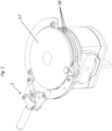
- Fig. 1 shows a perspective view of an exemplary embodiment of a tool 1 with a first arm 2 and a second arm 3 and a handle 4 according to the invention.
- the tool 1 is manually guided by means of the handle 4 once or several times around the piston 17.
- a holder 9 On the first arm 2 (in the area of the free end of the first arm 2), a holder 9 is detachably mounted by the fastening element 13, which in the state shown carries a cutting tool 10 (hereinafter referred to as "cutting blade") for the machining of the groove flanks of a selected piston groove 18 of a piston 17.
- cutting blade a cutting tool 10
- a guiding device is disposed on the second arm 2, which is here designed in the form of three guiding elements 8 distributed over the length of the second arm 2 and two guide rollers 16 disposed at the ends of the second arm 2.
- a first adjusting device is provided for adaption of tool 1 to different diameters of the rotation-symmetric component, which in the shown exemplary embodiment can change the swivel position of the first arm 2 and of the second arm 3 relative to each other.
- a knee lever with two lever arms 7 is provided for this purpose, where each lever arm 7 is connected at one end with one arm 2, 3 of the tool 1 and is connected on the other end (knee) to a spindle 6.
- a linear movement of the spindle 6 in the shown exemplary embodiment can occur via the rotatable disposed handle 4 on the bearing 5.
- the holder 9 in Fig 1 which is detachably mounted by the fastening element 13 on the first arm 2 (which can be swiveled around an axis formed by the fastening element 13), comprises a first adjusting device by means of which the contact force of the cutting blade 10 for the machining of the groove flanks, with which it is pressed against the groove flanks of the piston grooves 18, can be selected.
- the first adjusting device consists of a first and a second half shell 19, 20 of the holder 9 for the cutting blade 10 for the machining of the groove flanks (see also Fig. 4 ), whose distance to one another can be adjusted by a first control element 11 and locked by a second control element 12. The adjustment is carried out so as to achieve a larger contact force, the distance between the first and second half shell 19, 20 is increased. To achieve a smaller contact force, the distance between the first and second half shell 19, 20 is decreased.
- the fixing element 15, designed here as a screw is loosened and the cutting blade 10 for the machining of the groove flanks is removed and, as appropriate, re-inserted in turned position.
- an exchange of the cutting blade 10 for the machining of the groove flanks can also be done.
- a removal of the holder 9 from the first arm 2 is not required.
- the guide rollers 16 of the guiding device disposed on the second arm 3 facilitate guiding the tool 1 around the piston and limit the insertion depth of the guide elements 8 into the piston groove 18.
- Fig. 3 shows the tool 1 shown in Fig. 1 , wherein the holder 9 for the cutting blade 10 together with the cutting blade 10 for the machining of the groove flanks has been removed and wherein a cutting blade 22 for machining a groove base of the piston groove 18 was mounted instead. It is detachably fixed between two clamping jaws 21.
- the contact force, with which the cutting blade 22 is pressed against the groove base for machining a groove base, can be adjusted via the handle 4.
- a higher contact force results when the first and second arms 2, 3 are moved towards one another.
- a lower contact pressure results when the first and second arms 2, 3 are moved away from one another.
- Fig. 4 shows the holder 9 for the cutting blade 10 for the groove flanks together with the cutting blade 10 in isolation.
- the first adjusting device consists of a first and a second half shell 19, 20, which are connected to each other by a fixing element 23.
- the distance between the half shells 19, 20 relative to one another can be adjusted by the first control element 11 and locked by the second control element 12.
- the fixing element 15 for the cutting blade 10 is designed as a screw.
- first control element 11 of the first adjusting device for the contact force and the second control element 12 for the locking comprise an offset relative to one another (see Fig. 4b). Due to this geometrical situation, it is possible to adjust an angular position of the half shells 19, 20 relative to each other. This makes it possible to machine groove flanks that are disposed at a slopped angle.
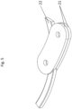
- Fig. 5 shows the holder of the cutting blade 22 for the groove base together with the cutting blade 22 in isolation. Here, it is clearly visible how the cutting blade 22 for machining of the groove base is fastened by the clamping between the clamping jaws 21.
- a tool 1 it is also possible, in the case of a tool 1 according to the invention, to develop further holders for holding other machining tools.
Landscapes
- Engineering & Computer Science (AREA)
- Mechanical Engineering (AREA)
- Physics & Mathematics (AREA)
- Optics & Photonics (AREA)
- Chemical & Material Sciences (AREA)
- Combustion & Propulsion (AREA)
- General Engineering & Computer Science (AREA)
- Finish Polishing, Edge Sharpening, And Grinding By Specific Grinding Devices (AREA)
- Automatic Tool Replacement In Machine Tools (AREA)
Description
- The invention relates to a tool for machining a groove of a rotation-symmetric component with the characteristics of the preamble of claim 1. Such a tool is known from
US 1 650 160 A . - A tool for machining a groove of a rotation-symmetric component is sometimes an essential aid in maintenance work of an internal combustion engine. The emphasis here is on easy handling and high quality of machining.
- An exemplary tool is disclosed in
US Pat. No. 3,188,670 . Here, a pincer-like tool, which comprises two arms, is placed over a piston to be machined and is placed in its groove with a machining element. A machining element for cleaning the groove is disposed on one arm, and a guiding device on the other arm for securing the position during the machining. The contact force of the machining element on the piston is thereby achieved in an undefined manner by a manual pressing together of the arms to one another. A similar tool is disclosed by theUS 1 650 160 A . - The drawback of tools for machining a groove of a piston known from the prior art is that such a class-specific tool provides only very little variability in relation to the diameter of a rotation-symmetric component. Furthermore, a defined setting of the contact force/machining force is not possible, since it is usually applied by manual pressing.
- Task of the invention is to provide a class-specific tool to ensure an enhanced ability for machining a groove of a rotation-symmetric component.
- This task is solved with a tool having the features of claim 1. Advantageous embodiments of the invention are defined in the dependent claims.
- It ensures a constant and precisely defined contact force across the entire area to be machined, which results in a high quality of the work result. Because a tool according to the invention can be adapted to different diameters by means of an first adjusting device, there is no longer a need to resort to a plurality of tools to be able to machine different components (in relation to their diameter).
- It can preferably be provided that at least one machining device is designed as a cutting tool. A cutting tool is mostly used in this context to clean or rework a groove of a rotation-symmetric component. Especially in maintenance work of pistons, which already had exposure to the operating conditions, this is often required, to eliminate impurities (such as soot) or slight damage to the edges of the groove.
- It can preferably be provided that a width of the at least one cutting tool is modifiable in a direction perpendicular to the extent of the at least one arm and parallel to a diameter of the at least one arm. Such a variability with respect to the width of a groove to be machined creates on the one hand the opportunity to carry out the machining in several steps in case of heavy dirt or damage, thereby approaching the final dimensions step by step, and on the other hand a degree of flexibility for machining different components with different widths is attained.
- It can be provided that the at least one cutting tool is attached interchangeably. With the help of such an arrangement it is ensured that the cutting tool can be replaced quickly and easily, if due to wear or damage on the cutting tool the desired quality of the machining can no longer be achieved.
- It is preferably provided that the at least one machining device is designed as an abrasive element. High accuracies and surface qualities can be achieved by machining a groove with an abrasive element. Such machining can be done, for example, after machining with a cutting tool.
- It can preferably be provided that a width of the at least one abrasive element is modifiable in a direction perpendicular to the extent of the at least one arm and parallel to a diameter of the at least one arm.
- It can preferably be provided that the at least one abrasive element is disposed interchangeably.
- It is preferably provided that the at least one machining device is disposed in such a way that a groove base of a groove is machinable.
- It can preferably be provided that the at least one machining device is disposed in such a way that the at least one groove flank of a groove is machinable.
- It can preferably be provided that the at least one machining device is capable of specifically being tilted to a sloping position. Such tilting of the machining device to a sloping position ensures a machinability of slopped grooves (grooves which have an angular position or an angular position of the groove flanks).
- It can be provided that a guiding device to guide the tool on the groove is provided on at least one arm.
- It is preferably provided that guiding elements of the guiding device are designed to allow a rotation of the tool around the rotation-symmetric component to be machined, but ensure a particular position in axial direction.
- It can preferably be provided that the guiding device is disposed interchangeably.
- It can be provided that the guiding device is modifiable in its width.
- Preferably a first arm and a second arm are provided.
- It can preferably be provided that on the first arm the at least one machining device is provided and that on the second arm the guiding device for the guiding of the tool is provided.
- Exemplary embodiments of the invention are discussed with reference to the Figures. The drawings in detail:
- Fig. 1
- shows a tool according to the invention in perspective view
- Fig. 2
- shows the tool of
Fig. 1 in a position that is applied to a piston - Fig. 3
- shows the tool of
Fig. 1 (not part of the invention) - Figs. 4a, b
- show the holder together with the cutting blade for the groove flanks in isolation
- Fig. 5
- shows the holder together with the cutting blade for the groove base in isolation (not part of the invention)
- In the figures shown, the rotation-symmetric component to be machined is designed in an exemplary manner as
piston 17 with at least onepiston groove 18 to be cleaned. -
Fig. 1 shows a perspective view of an exemplary embodiment of a tool 1 with afirst arm 2 and asecond arm 3 and ahandle 4 according to the invention. For the machining of apiston groove 18 of a piston 17 (seeFig. 2 ) the tool 1 is manually guided by means of thehandle 4 once or several times around thepiston 17. - On the first arm 2 (in the area of the free end of the first arm 2), a
holder 9 is detachably mounted by thefastening element 13, which in the state shown carries a cutting tool 10 (hereinafter referred to as "cutting blade") for the machining of the groove flanks of a selectedpiston groove 18 of apiston 17. - A guiding device is disposed on the
second arm 2, which is here designed in the form of three guidingelements 8 distributed over the length of thesecond arm 2 and twoguide rollers 16 disposed at the ends of thesecond arm 2. - Between the
first arm 2 and thesecond arm 3 is agap 14 designed for positioning of the rotation-symmetric component to be machined (here a piston 17 - seeFig. 2 ). A first adjusting device is provided for adaption of tool 1 to different diameters of the rotation-symmetric component, which in the shown exemplary embodiment can change the swivel position of thefirst arm 2 and of thesecond arm 3 relative to each other. A knee lever with twolever arms 7 is provided for this purpose, where eachlever arm 7 is connected at one end with onearm spindle 6. A linear movement of thespindle 6 in the shown exemplary embodiment can occur via the rotatable disposedhandle 4 on thebearing 5. If thespindle 6 moves further out of thebearing 5, this increases the diameter of thegap 14 for positioning of the rotation-symmetric component to be machined. If thespindle 6 moves further into thebearing 5, this decreases the diameter of thegap 14 for positioning of the rotation-symmetric component to be machined. - The
holder 9 inFig 1 , which is detachably mounted by thefastening element 13 on the first arm 2 (which can be swiveled around an axis formed by the fastening element 13), comprises a first adjusting device by means of which the contact force of thecutting blade 10 for the machining of the groove flanks, with which it is pressed against the groove flanks of thepiston grooves 18, can be selected. The first adjusting device consists of a first and asecond half shell holder 9 for thecutting blade 10 for the machining of the groove flanks (see alsoFig. 4 ), whose distance to one another can be adjusted by afirst control element 11 and locked by asecond control element 12. The adjustment is carried out so as to achieve a larger contact force, the distance between the first andsecond half shell second half shell - To change the
cutting blade 10 for the machining of the groove flanks (which is designed here as a rotating cutting blade), the fixingelement 15, designed here as a screw, is loosened and thecutting blade 10 for the machining of the groove flanks is removed and, as appropriate, re-inserted in turned position. Of course, an exchange of thecutting blade 10 for the machining of the groove flanks can also be done. A removal of theholder 9 from thefirst arm 2 is not required. - The
guide rollers 16 of the guiding device disposed on thesecond arm 3 facilitate guiding the tool 1 around the piston and limit the insertion depth of theguide elements 8 into thepiston groove 18. -
Fig. 3 shows the tool 1 shown inFig. 1 , wherein theholder 9 for thecutting blade 10 together with thecutting blade 10 for the machining of the groove flanks has been removed and wherein acutting blade 22 for machining a groove base of thepiston groove 18 was mounted instead. It is detachably fixed between two clampingjaws 21. The contact force, with which thecutting blade 22 is pressed against the groove base for machining a groove base, can be adjusted via thehandle 4. A higher contact force results when the first andsecond arms second arms -
Fig. 4 shows theholder 9 for thecutting blade 10 for the groove flanks together with thecutting blade 10 in isolation. It is clearly visible that (as already described forFig. 1 ) the first adjusting device consists of a first and asecond half shell element 23. For the machining of the groove flanks, the distance between thehalf shells first control element 11 and locked by thesecond control element 12. In order to detachably dispose thecutting blade 10 on thefirst half shell 19, in this exemplary embodiment the fixingelement 15 for thecutting blade 10 is designed as a screw. It should be noted that thefirst control element 11 of the first adjusting device for the contact force and thesecond control element 12 for the locking comprise an offset relative to one another (see Fig. 4b). Due to this geometrical situation, it is possible to adjust an angular position of thehalf shells -
Fig. 5 shows the holder of thecutting blade 22 for the groove base together with thecutting blade 22 in isolation. Here, it is clearly visible how thecutting blade 22 for machining of the groove base is fastened by the clamping between the clampingjaws 21. - It is also possible, in the case of a tool 1 according to the invention, to develop further holders for holding other machining tools. Here, reference is made, by way of example, to a holder for an abrasive element for fine machining.
-
- 1
- tool
- 2
- first arm
- 3
- second arm
- 4
- handle
- 5
- bearing
- 6
- spindle
- 7
- lever arm of the knee lever
- 8
- guiding elements of the guiding device
- 9
- holder for the cutting blade for the groove flanks
- 10
- cutting tool (cutting blade) for groove flanks
- 11
- first control element of the first adjusting device for the contact force
- 12
- second control element for the first adjusting device
- 13, 13'
- fastening element for holder
- 14
- gap for positioning the component to be machined
- 15
- fixing element for cutting blade
- 16
- guide rollers of the guiding device
- 17
- piston
- 18
- piston groove
- 19
- first half shell of the holder for the cutting blade for the groove flanks
- 20
- second half shell of the holder for the cutting blade for the groove flanks
- 21
- clamping jaws of the cutting blade for the groove base
- 22
- cutting blade for the groove base
- 23
- fixing element for first adjusting device
Claims (15)
- A tool (1) for machining a groove (18) of a rotation-symmetric component, preferably a piston (17) of an internal combustion engine, wherein the machining is carried out by a rotation of the tool (1) around an axis of symmetry of the rotation-symmetric component to be machined, wherein• the tool (1) comprises at least one arm (2, 3) which is disposed in such a way that a circumference of the rotation-symmetric component can at least be partially enclosed,• wherein a machining device for machining of the groove (18) is provided on the at least one arm (2, 3),wherein at least one first adjusting device is provided, with the help of which a contact force on the rotation-symmetric component of the at least one machining device can be selected, and wherein the tool (1) comprises a second adjusting device, with which the tool can be adapted to different diameters of a rotation-symmetric component, characterized in that the first adjusting device comprises a first and a second half shell (19, 20), whose distance to one another can be adjusted by a first control element (11) and locked by a second control element (12).
- A tool (1) for machining a groove (18) according to claim 1, characterized in that at least one machining device is designed as a cutting tool (10).
- A tool (1) for machining a groove (18) according to claim 2, characterized in that a width of the at least one cutting tool is modifiable (10) in a direction perpendicular to the extent of the at least one arm (2, 3) and parallel to a diameter of the at least one arm (2, 3).
- A tool (1) for machining a groove (18) according to claim 2 or 3, characterized in that the at least one cutting tool (10) is attached interchangeably.
- A tool (1) for machining a groove (18) according to claim 1, characterized in that the at least one machining device is designed as an abrasive element.
- A tool (1) for machining a groove (18) according to claim 5, characterized in that a width of the at least one abrasive element is modifiable in a direction perpendicular to the extent of the at least one arm (2, 3) and parallel to a diameter of the at least one arm (2, 3).
- A tool (1) for machining a groove (18) according to claim 5 or 6, characterized in that the at least one abrasive element is attached interchangeably.
- A tool (1) for machining a groove (18) according to one of the preceding claims, characterized in that the at least one machining device is disposed such that a groove base of the groove (18) can be machined.
- A tool (1) for machining a groove (18) according to one of the preceding claims, characterized in that the at least one machining device is disposed such that at least a groove flank of the groove (18) can be machined.
- A tool (1) for machining a groove (18) according to one of the preceding claims, characterized in that the first and the second control element (11, 12) comprise an offset relative to each other, so that the at least one machining device is capable of specifically being tilted to a sloping position.
- A tool (1) for machining a groove (18) according to one of the preceding claims, characterized in that a guiding device for guiding the tool (1) on the groove (18) is provided on the at least one arm (2, 3).
- A tool (1) for machining a groove (18) according to one of the preceding claims, characterized in that guiding elements (8) of a guiding device are designed to allow a rotation of the tool around the rotation-symmetric component to be machined, but ensure a particular position in axial direction.
- A tool (1) for machining a groove (18) according to one of the preceding claims, characterized in that the guiding device is disposed interchangeably.
- A tool (1) for machining a groove (18) of a rotation-symmetric component according to one of the preceding claims, characterized in that a first arm (2) and a second arm (3) are provided.
- A tool (1) for machining a groove (18) of a rotation-symmetric component according to claim 14, characterized in that the at least one machining device is provided on the first arm (2) and the guiding device for guiding the tool (1) is provided on the second arm (3).
Applications Claiming Priority (2)
| Application Number | Priority Date | Filing Date | Title |
|---|---|---|---|
| ATA50605/2016A AT518770B1 (en) | 2016-07-07 | 2016-07-07 | Tool for machining a groove |
| PCT/EP2017/067084 WO2018007584A1 (en) | 2016-07-07 | 2017-07-07 | Piston groove machining tool |
Publications (2)
| Publication Number | Publication Date |
|---|---|
| EP3481572A1 EP3481572A1 (en) | 2019-05-15 |
| EP3481572B1 true EP3481572B1 (en) | 2024-02-28 |
Family
ID=59298457
Family Applications (1)
| Application Number | Title | Priority Date | Filing Date |
|---|---|---|---|
| EP17737260.4A Active EP3481572B1 (en) | 2016-07-07 | 2017-07-07 | A tool for machining a groove of a rotation-symmetric component |
Country Status (5)
| Country | Link |
|---|---|
| US (1) | US10888930B2 (en) |
| EP (1) | EP3481572B1 (en) |
| AT (1) | AT518770B1 (en) |
| CA (1) | CA3028876A1 (en) |
| WO (1) | WO2018007584A1 (en) |
Family Cites Families (24)
| Publication number | Priority date | Publication date | Assignee | Title |
|---|---|---|---|---|
| US1351057A (en) * | 1917-11-14 | 1920-08-31 | Louis De F Munger | Piston-groove tool |
| US1346838A (en) * | 1919-04-09 | 1920-07-20 | Muller Christian | Piston-grooving tool |
| US1397312A (en) * | 1920-10-18 | 1921-11-15 | Joe M Bowman | Piston-groove-cleaning tool |
| US1491847A (en) * | 1922-08-01 | 1924-04-29 | Creed Roy Cleveland | Piston-groove tool |
| US1650160A (en) * | 1926-05-20 | 1927-11-22 | Walter L Slack | Device for operating on piston-ring grooves |
| US1654851A (en) * | 1926-08-30 | 1928-01-03 | Homer S Albert | Carbon scraper for piston-ring grooves |
| US1715289A (en) * | 1927-06-06 | 1929-05-28 | Superior Piston Ring Company | Cleaner for piston-ring grooves |
| US1820792A (en) * | 1930-03-12 | 1931-08-25 | Budlong & Funchess Motor Produ | Regrooving tool |
| US1821891A (en) * | 1930-05-09 | 1931-09-01 | Homer W Presly | Carbon removing tool |
| US2018930A (en) * | 1934-11-23 | 1935-10-29 | Charles D Stromgren | Piston ring-groove scraper and groove deepener |
| US2109857A (en) * | 1935-10-14 | 1938-03-01 | Zim Mfg Company | Tool for cleaning and deepening grooves in pistons |
| US2124757A (en) | 1936-06-01 | 1938-07-26 | Aircraft Specialties Inc | Piston ring groove cleaner |
| US2194686A (en) * | 1938-10-01 | 1940-03-26 | Charles W Berggren | Portable piston groover and facer |
| US2344880A (en) * | 1943-07-22 | 1944-03-21 | John T Crow | Groove dressing tool |
| US2480456A (en) * | 1944-03-23 | 1949-08-30 | Ellison Houston | Piston ring groove cleaner and deepener |
| US2570416A (en) * | 1946-04-17 | 1951-10-09 | Joseph J Wittman | Piston regrooving tool |
| US2566048A (en) * | 1946-10-25 | 1951-08-28 | Perfect Circle Corp | Piston regrooving tool |
| US2695542A (en) * | 1950-05-25 | 1954-11-30 | Woodrow W Ward | Piston ring groove cleaner |
| US3188670A (en) * | 1963-01-18 | 1965-06-15 | William J Babb | Piston groove cleaner |
| US3299751A (en) * | 1964-12-29 | 1967-01-24 | William A Coninx | Piston groove cutting tool |
| US3323161A (en) | 1965-09-03 | 1967-06-06 | Aircraft Specialties Inc | Piston groove cleaner |
| US3510902A (en) * | 1967-12-20 | 1970-05-12 | Aircraft Specialties Inc | Piston ring groove cleaner |
| DE2007647A1 (en) * | 1970-02-19 | 1971-09-09 | Maschinenfabrik Augsburg Nürnberg AG, 8500 Nürnberg | Method and device for Her provide of annular grooves and / or the running flat profile on the sealing jacket of a steel piston of in particular Brennkraftma machines |
| US4079477A (en) | 1976-08-04 | 1978-03-21 | Helt Raymond E | Apparatus for cleaning piston ring grooves |
-
2016
- 2016-07-07 AT ATA50605/2016A patent/AT518770B1/en active
-
2017
- 2017-07-07 EP EP17737260.4A patent/EP3481572B1/en active Active
- 2017-07-07 WO PCT/EP2017/067084 patent/WO2018007584A1/en not_active Ceased
- 2017-07-07 CA CA3028876A patent/CA3028876A1/en not_active Abandoned
- 2017-07-07 US US16/312,313 patent/US10888930B2/en active Active
Also Published As
| Publication number | Publication date |
|---|---|
| US20190232376A1 (en) | 2019-08-01 |
| AT518770A4 (en) | 2018-01-15 |
| US10888930B2 (en) | 2021-01-12 |
| AT518770B1 (en) | 2018-01-15 |
| WO2018007584A1 (en) | 2018-01-11 |
| CA3028876A1 (en) | 2018-01-11 |
| EP3481572A1 (en) | 2019-05-15 |
Similar Documents
| Publication | Publication Date | Title |
|---|---|---|
| JP5883016B2 (en) | Method for machining the casing of an aircraft turboshaft engine and scraper tool for carrying out said method | |
| JP5894270B2 (en) | Tubular workpiece machining equipment | |
| KR101443776B1 (en) | Device for cutting bar-shaped or tubular workpieces | |
| WO2012101319A1 (en) | Apparatus for machining, especially for beveling the end of a tubular or round bar type piece | |
| JP7063790B2 (en) | Work processing equipment | |
| EP3181279B1 (en) | C-type tubing cutter | |
| CA1135084A (en) | Peeling apparatus | |
| CN1950177B (en) | Manual grinding device | |
| JP7181099B2 (en) | honing tools | |
| CA2822356C (en) | Cutting tool having a shank-mounted adjustment ring | |
| US10888930B2 (en) | Piston groove machining tool | |
| EP1048384B1 (en) | System for presetting the cutting tools of a cut-off machine for a pipe or a shaft | |
| JP2021030324A (en) | Tool holder cleaner | |
| JPH07314246A (en) | Trimming tool | |
| KR101896770B1 (en) | Honing tool device | |
| JP4120912B2 (en) | Cable core cutting device | |
| RU2414333C2 (en) | Milling head | |
| JP2010173000A (en) | Workpiece for drill including a pair of oil supply hole, centering method of workpiece with hole, and centering device | |
| US20070048102A1 (en) | Arc Cutter For Stone or Ceramic Material | |
| KR20160094260A (en) | Method of texturizing a sliding member and the sliding member | |
| JP4375870B2 (en) | Rotating guide bush | |
| RU96053U1 (en) | DEVICE FOR FINAL PROCESSING INTERNAL CYLINDRICAL SURFACES | |
| JP2017200723A (en) | Brushing device for working of workpieces | |
| DK9700136U3 (en) | Angle tube grinder | |
| KR101552015B1 (en) | Apparatus for lapping processing |
Legal Events
| Date | Code | Title | Description |
|---|---|---|---|
| STAA | Information on the status of an ep patent application or granted ep patent |
Free format text: STATUS: UNKNOWN |
|
| STAA | Information on the status of an ep patent application or granted ep patent |
Free format text: STATUS: THE INTERNATIONAL PUBLICATION HAS BEEN MADE |
|
| PUAI | Public reference made under article 153(3) epc to a published international application that has entered the european phase |
Free format text: ORIGINAL CODE: 0009012 |
|
| STAA | Information on the status of an ep patent application or granted ep patent |
Free format text: STATUS: REQUEST FOR EXAMINATION WAS MADE |
|
| 17P | Request for examination filed |
Effective date: 20190207 |
|
| AK | Designated contracting states |
Kind code of ref document: A1 Designated state(s): AL AT BE BG CH CY CZ DE DK EE ES FI FR GB GR HR HU IE IS IT LI LT LU LV MC MK MT NL NO PL PT RO RS SE SI SK SM TR |
|
| AX | Request for extension of the european patent |
Extension state: BA ME |
|
| RAP1 | Party data changed (applicant data changed or rights of an application transferred) |
Owner name: INNIO JENBACHER GMBH & CO OG |
|
| DAV | Request for validation of the european patent (deleted) | ||
| DAX | Request for extension of the european patent (deleted) | ||
| P01 | Opt-out of the competence of the unified patent court (upc) registered |
Effective date: 20230614 |
|
| GRAP | Despatch of communication of intention to grant a patent |
Free format text: ORIGINAL CODE: EPIDOSNIGR1 |
|
| STAA | Information on the status of an ep patent application or granted ep patent |
Free format text: STATUS: GRANT OF PATENT IS INTENDED |
|
| INTG | Intention to grant announced |
Effective date: 20231128 |
|
| RIN1 | Information on inventor provided before grant (corrected) |
Inventor name: HOTTER, PATRICK Inventor name: NASCHBERGER, MANUEL |
|
| GRAS | Grant fee paid |
Free format text: ORIGINAL CODE: EPIDOSNIGR3 |
|
| GRAA | (expected) grant |
Free format text: ORIGINAL CODE: 0009210 |
|
| STAA | Information on the status of an ep patent application or granted ep patent |
Free format text: STATUS: THE PATENT HAS BEEN GRANTED |
|
| AK | Designated contracting states |
Kind code of ref document: B1 Designated state(s): AL AT BE BG CH CY CZ DE DK EE ES FI FR GB GR HR HU IE IS IT LI LT LU LV MC MK MT NL NO PL PT RO RS SE SI SK SM TR |
|
| REG | Reference to a national code |
Ref country code: GB Ref legal event code: FG4D |
|
| REG | Reference to a national code |
Ref country code: CH Ref legal event code: EP |
|
| REG | Reference to a national code |
Ref country code: DE Ref legal event code: R096 Ref document number: 602017079526 Country of ref document: DE |
|
| REG | Reference to a national code |
Ref country code: IE Ref legal event code: FG4D |
|
| REG | Reference to a national code |
Ref country code: LT Ref legal event code: MG9D |
|
| PG25 | Lapsed in a contracting state [announced via postgrant information from national office to epo] |
Ref country code: IS Free format text: LAPSE BECAUSE OF FAILURE TO SUBMIT A TRANSLATION OF THE DESCRIPTION OR TO PAY THE FEE WITHIN THE PRESCRIBED TIME-LIMIT Effective date: 20240628 |
|
| REG | Reference to a national code |
Ref country code: NL Ref legal event code: MP Effective date: 20240228 |
|
| PG25 | Lapsed in a contracting state [announced via postgrant information from national office to epo] |
Ref country code: LT Free format text: LAPSE BECAUSE OF FAILURE TO SUBMIT A TRANSLATION OF THE DESCRIPTION OR TO PAY THE FEE WITHIN THE PRESCRIBED TIME-LIMIT Effective date: 20240228 |
|
| PG25 | Lapsed in a contracting state [announced via postgrant information from national office to epo] |
Ref country code: GR Free format text: LAPSE BECAUSE OF FAILURE TO SUBMIT A TRANSLATION OF THE DESCRIPTION OR TO PAY THE FEE WITHIN THE PRESCRIBED TIME-LIMIT Effective date: 20240529 |
|
| PG25 | Lapsed in a contracting state [announced via postgrant information from national office to epo] |
Ref country code: HR Free format text: LAPSE BECAUSE OF FAILURE TO SUBMIT A TRANSLATION OF THE DESCRIPTION OR TO PAY THE FEE WITHIN THE PRESCRIBED TIME-LIMIT Effective date: 20240228 Ref country code: NL Free format text: LAPSE BECAUSE OF FAILURE TO SUBMIT A TRANSLATION OF THE DESCRIPTION OR TO PAY THE FEE WITHIN THE PRESCRIBED TIME-LIMIT Effective date: 20240228 Ref country code: RS Free format text: LAPSE BECAUSE OF FAILURE TO SUBMIT A TRANSLATION OF THE DESCRIPTION OR TO PAY THE FEE WITHIN THE PRESCRIBED TIME-LIMIT Effective date: 20240528 |
|
| PG25 | Lapsed in a contracting state [announced via postgrant information from national office to epo] |
Ref country code: ES Free format text: LAPSE BECAUSE OF FAILURE TO SUBMIT A TRANSLATION OF THE DESCRIPTION OR TO PAY THE FEE WITHIN THE PRESCRIBED TIME-LIMIT Effective date: 20240228 |
|
| PG25 | Lapsed in a contracting state [announced via postgrant information from national office to epo] |
Ref country code: RS Free format text: LAPSE BECAUSE OF FAILURE TO SUBMIT A TRANSLATION OF THE DESCRIPTION OR TO PAY THE FEE WITHIN THE PRESCRIBED TIME-LIMIT Effective date: 20240528 Ref country code: NO Free format text: LAPSE BECAUSE OF FAILURE TO SUBMIT A TRANSLATION OF THE DESCRIPTION OR TO PAY THE FEE WITHIN THE PRESCRIBED TIME-LIMIT Effective date: 20240528 Ref country code: NL Free format text: LAPSE BECAUSE OF FAILURE TO SUBMIT A TRANSLATION OF THE DESCRIPTION OR TO PAY THE FEE WITHIN THE PRESCRIBED TIME-LIMIT Effective date: 20240228 Ref country code: LT Free format text: LAPSE BECAUSE OF FAILURE TO SUBMIT A TRANSLATION OF THE DESCRIPTION OR TO PAY THE FEE WITHIN THE PRESCRIBED TIME-LIMIT Effective date: 20240228 Ref country code: IS Free format text: LAPSE BECAUSE OF FAILURE TO SUBMIT A TRANSLATION OF THE DESCRIPTION OR TO PAY THE FEE WITHIN THE PRESCRIBED TIME-LIMIT Effective date: 20240628 Ref country code: HR Free format text: LAPSE BECAUSE OF FAILURE TO SUBMIT A TRANSLATION OF THE DESCRIPTION OR TO PAY THE FEE WITHIN THE PRESCRIBED TIME-LIMIT Effective date: 20240228 Ref country code: GR Free format text: LAPSE BECAUSE OF FAILURE TO SUBMIT A TRANSLATION OF THE DESCRIPTION OR TO PAY THE FEE WITHIN THE PRESCRIBED TIME-LIMIT Effective date: 20240529 Ref country code: FI Free format text: LAPSE BECAUSE OF FAILURE TO SUBMIT A TRANSLATION OF THE DESCRIPTION OR TO PAY THE FEE WITHIN THE PRESCRIBED TIME-LIMIT Effective date: 20240228 Ref country code: ES Free format text: LAPSE BECAUSE OF FAILURE TO SUBMIT A TRANSLATION OF THE DESCRIPTION OR TO PAY THE FEE WITHIN THE PRESCRIBED TIME-LIMIT Effective date: 20240228 Ref country code: BG Free format text: LAPSE BECAUSE OF FAILURE TO SUBMIT A TRANSLATION OF THE DESCRIPTION OR TO PAY THE FEE WITHIN THE PRESCRIBED TIME-LIMIT Effective date: 20240228 |
|
| PG25 | Lapsed in a contracting state [announced via postgrant information from national office to epo] |
Ref country code: PT Free format text: LAPSE BECAUSE OF FAILURE TO SUBMIT A TRANSLATION OF THE DESCRIPTION OR TO PAY THE FEE WITHIN THE PRESCRIBED TIME-LIMIT Effective date: 20240628 Ref country code: PL Free format text: LAPSE BECAUSE OF FAILURE TO SUBMIT A TRANSLATION OF THE DESCRIPTION OR TO PAY THE FEE WITHIN THE PRESCRIBED TIME-LIMIT Effective date: 20240228 |
|
| REG | Reference to a national code |
Ref country code: AT Ref legal event code: MK05 Ref document number: 1660793 Country of ref document: AT Kind code of ref document: T Effective date: 20240228 |
|
| PG25 | Lapsed in a contracting state [announced via postgrant information from national office to epo] |
Ref country code: SE Free format text: LAPSE BECAUSE OF FAILURE TO SUBMIT A TRANSLATION OF THE DESCRIPTION OR TO PAY THE FEE WITHIN THE PRESCRIBED TIME-LIMIT Effective date: 20240228 Ref country code: PT Free format text: LAPSE BECAUSE OF FAILURE TO SUBMIT A TRANSLATION OF THE DESCRIPTION OR TO PAY THE FEE WITHIN THE PRESCRIBED TIME-LIMIT Effective date: 20240628 Ref country code: PL Free format text: LAPSE BECAUSE OF FAILURE TO SUBMIT A TRANSLATION OF THE DESCRIPTION OR TO PAY THE FEE WITHIN THE PRESCRIBED TIME-LIMIT Effective date: 20240228 Ref country code: LV Free format text: LAPSE BECAUSE OF FAILURE TO SUBMIT A TRANSLATION OF THE DESCRIPTION OR TO PAY THE FEE WITHIN THE PRESCRIBED TIME-LIMIT Effective date: 20240228 |
|
| PG25 | Lapsed in a contracting state [announced via postgrant information from national office to epo] |
Ref country code: DK Free format text: LAPSE BECAUSE OF FAILURE TO SUBMIT A TRANSLATION OF THE DESCRIPTION OR TO PAY THE FEE WITHIN THE PRESCRIBED TIME-LIMIT Effective date: 20240228 |
|
| PG25 | Lapsed in a contracting state [announced via postgrant information from national office to epo] |
Ref country code: SM Free format text: LAPSE BECAUSE OF FAILURE TO SUBMIT A TRANSLATION OF THE DESCRIPTION OR TO PAY THE FEE WITHIN THE PRESCRIBED TIME-LIMIT Effective date: 20240228 |
|
| PG25 | Lapsed in a contracting state [announced via postgrant information from national office to epo] |
Ref country code: EE Free format text: LAPSE BECAUSE OF FAILURE TO SUBMIT A TRANSLATION OF THE DESCRIPTION OR TO PAY THE FEE WITHIN THE PRESCRIBED TIME-LIMIT Effective date: 20240228 Ref country code: CZ Free format text: LAPSE BECAUSE OF FAILURE TO SUBMIT A TRANSLATION OF THE DESCRIPTION OR TO PAY THE FEE WITHIN THE PRESCRIBED TIME-LIMIT Effective date: 20240228 |
|
| PG25 | Lapsed in a contracting state [announced via postgrant information from national office to epo] |
Ref country code: AT Free format text: LAPSE BECAUSE OF FAILURE TO SUBMIT A TRANSLATION OF THE DESCRIPTION OR TO PAY THE FEE WITHIN THE PRESCRIBED TIME-LIMIT Effective date: 20240228 |
|
| PG25 | Lapsed in a contracting state [announced via postgrant information from national office to epo] |
Ref country code: SK Free format text: LAPSE BECAUSE OF FAILURE TO SUBMIT A TRANSLATION OF THE DESCRIPTION OR TO PAY THE FEE WITHIN THE PRESCRIBED TIME-LIMIT Effective date: 20240228 |
|
| PG25 | Lapsed in a contracting state [announced via postgrant information from national office to epo] |
Ref country code: SM Free format text: LAPSE BECAUSE OF FAILURE TO SUBMIT A TRANSLATION OF THE DESCRIPTION OR TO PAY THE FEE WITHIN THE PRESCRIBED TIME-LIMIT Effective date: 20240228 Ref country code: SK Free format text: LAPSE BECAUSE OF FAILURE TO SUBMIT A TRANSLATION OF THE DESCRIPTION OR TO PAY THE FEE WITHIN THE PRESCRIBED TIME-LIMIT Effective date: 20240228 Ref country code: RO Free format text: LAPSE BECAUSE OF FAILURE TO SUBMIT A TRANSLATION OF THE DESCRIPTION OR TO PAY THE FEE WITHIN THE PRESCRIBED TIME-LIMIT Effective date: 20240228 Ref country code: EE Free format text: LAPSE BECAUSE OF FAILURE TO SUBMIT A TRANSLATION OF THE DESCRIPTION OR TO PAY THE FEE WITHIN THE PRESCRIBED TIME-LIMIT Effective date: 20240228 Ref country code: DK Free format text: LAPSE BECAUSE OF FAILURE TO SUBMIT A TRANSLATION OF THE DESCRIPTION OR TO PAY THE FEE WITHIN THE PRESCRIBED TIME-LIMIT Effective date: 20240228 Ref country code: CZ Free format text: LAPSE BECAUSE OF FAILURE TO SUBMIT A TRANSLATION OF THE DESCRIPTION OR TO PAY THE FEE WITHIN THE PRESCRIBED TIME-LIMIT Effective date: 20240228 Ref country code: AT Free format text: LAPSE BECAUSE OF FAILURE TO SUBMIT A TRANSLATION OF THE DESCRIPTION OR TO PAY THE FEE WITHIN THE PRESCRIBED TIME-LIMIT Effective date: 20240228 |
|
| REG | Reference to a national code |
Ref country code: DE Ref legal event code: R097 Ref document number: 602017079526 Country of ref document: DE |
|
| PLBE | No opposition filed within time limit |
Free format text: ORIGINAL CODE: 0009261 |
|
| STAA | Information on the status of an ep patent application or granted ep patent |
Free format text: STATUS: NO OPPOSITION FILED WITHIN TIME LIMIT |
|
| 26N | No opposition filed |
Effective date: 20241129 |
|
| PG25 | Lapsed in a contracting state [announced via postgrant information from national office to epo] |
Ref country code: MC Free format text: LAPSE BECAUSE OF FAILURE TO SUBMIT A TRANSLATION OF THE DESCRIPTION OR TO PAY THE FEE WITHIN THE PRESCRIBED TIME-LIMIT Effective date: 20240228 |
|
| REG | Reference to a national code |
Ref country code: CH Ref legal event code: PL |
|
| PG25 | Lapsed in a contracting state [announced via postgrant information from national office to epo] |
Ref country code: LU Free format text: LAPSE BECAUSE OF NON-PAYMENT OF DUE FEES Effective date: 20240707 |
|
| PG25 | Lapsed in a contracting state [announced via postgrant information from national office to epo] |
Ref country code: LU Free format text: LAPSE BECAUSE OF NON-PAYMENT OF DUE FEES Effective date: 20240707 |
|
| PG25 | Lapsed in a contracting state [announced via postgrant information from national office to epo] |
Ref country code: SI Free format text: LAPSE BECAUSE OF FAILURE TO SUBMIT A TRANSLATION OF THE DESCRIPTION OR TO PAY THE FEE WITHIN THE PRESCRIBED TIME-LIMIT Effective date: 20240228 Ref country code: CH Free format text: LAPSE BECAUSE OF NON-PAYMENT OF DUE FEES Effective date: 20240731 Ref country code: BE Free format text: LAPSE BECAUSE OF NON-PAYMENT OF DUE FEES Effective date: 20240731 |
|
| REG | Reference to a national code |
Ref country code: BE Ref legal event code: MM Effective date: 20240731 |
|
| PGFP | Annual fee paid to national office [announced via postgrant information from national office to epo] |
Ref country code: GB Payment date: 20250619 Year of fee payment: 9 |
|
| PGFP | Annual fee paid to national office [announced via postgrant information from national office to epo] |
Ref country code: FR Payment date: 20250620 Year of fee payment: 9 |
|
| PG25 | Lapsed in a contracting state [announced via postgrant information from national office to epo] |
Ref country code: IE Free format text: LAPSE BECAUSE OF NON-PAYMENT OF DUE FEES Effective date: 20240707 |
|
| PGFP | Annual fee paid to national office [announced via postgrant information from national office to epo] |
Ref country code: DE Payment date: 20250620 Year of fee payment: 9 |
|
| PGFP | Annual fee paid to national office [announced via postgrant information from national office to epo] |
Ref country code: IT Payment date: 20250619 Year of fee payment: 9 |
|
| PG25 | Lapsed in a contracting state [announced via postgrant information from national office to epo] |
Ref country code: CY Free format text: LAPSE BECAUSE OF FAILURE TO SUBMIT A TRANSLATION OF THE DESCRIPTION OR TO PAY THE FEE WITHIN THE PRESCRIBED TIME-LIMIT; INVALID AB INITIO Effective date: 20170707 |
|
| PG25 | Lapsed in a contracting state [announced via postgrant information from national office to epo] |
Ref country code: HU Free format text: LAPSE BECAUSE OF FAILURE TO SUBMIT A TRANSLATION OF THE DESCRIPTION OR TO PAY THE FEE WITHIN THE PRESCRIBED TIME-LIMIT; INVALID AB INITIO Effective date: 20170707 |