EP3481314B1 - Chest wall repair device - Google Patents
Chest wall repair device Download PDFInfo
- Publication number
- EP3481314B1 EP3481314B1 EP17828328.9A EP17828328A EP3481314B1 EP 3481314 B1 EP3481314 B1 EP 3481314B1 EP 17828328 A EP17828328 A EP 17828328A EP 3481314 B1 EP3481314 B1 EP 3481314B1
- Authority
- EP
- European Patent Office
- Prior art keywords
- plate sections
- sternum
- plate
- elastomeric portion
- central elastomeric
- Prior art date
- Legal status (The legal status is an assumption and is not a legal conclusion. Google has not performed a legal analysis and makes no representation as to the accuracy of the status listed.)
- Active
Links
Images


Classifications
-
- A—HUMAN NECESSITIES
- A61—MEDICAL OR VETERINARY SCIENCE; HYGIENE
- A61B—DIAGNOSIS; SURGERY; IDENTIFICATION
- A61B17/00—Surgical instruments, devices or methods
- A61B17/56—Surgical instruments or methods for treatment of bones or joints; Devices specially adapted therefor
- A61B17/58—Surgical instruments or methods for treatment of bones or joints; Devices specially adapted therefor for osteosynthesis, e.g. bone plates, screws or setting implements
- A61B17/68—Internal fixation devices, including fasteners and spinal fixators, even if a part thereof projects from the skin
- A61B17/80—Cortical plates, i.e. bone plates; Instruments for holding or positioning cortical plates, or for compressing bones attached to cortical plates
- A61B17/8085—Cortical plates, i.e. bone plates; Instruments for holding or positioning cortical plates, or for compressing bones attached to cortical plates with pliable or malleable elements or having a mesh-like structure, e.g. small strips
-
- A—HUMAN NECESSITIES
- A61—MEDICAL OR VETERINARY SCIENCE; HYGIENE
- A61B—DIAGNOSIS; SURGERY; IDENTIFICATION
- A61B17/00—Surgical instruments, devices or methods
- A61B17/56—Surgical instruments or methods for treatment of bones or joints; Devices specially adapted therefor
- A61B17/58—Surgical instruments or methods for treatment of bones or joints; Devices specially adapted therefor for osteosynthesis, e.g. bone plates, screws or setting implements
- A61B17/68—Internal fixation devices, including fasteners and spinal fixators, even if a part thereof projects from the skin
- A61B17/80—Cortical plates, i.e. bone plates; Instruments for holding or positioning cortical plates, or for compressing bones attached to cortical plates
- A61B17/8061—Cortical plates, i.e. bone plates; Instruments for holding or positioning cortical plates, or for compressing bones attached to cortical plates specially adapted for particular bones
- A61B17/8076—Cortical plates, i.e. bone plates; Instruments for holding or positioning cortical plates, or for compressing bones attached to cortical plates specially adapted for particular bones for the ribs or the sternum
-
- A—HUMAN NECESSITIES
- A61—MEDICAL OR VETERINARY SCIENCE; HYGIENE
- A61B—DIAGNOSIS; SURGERY; IDENTIFICATION
- A61B17/00—Surgical instruments, devices or methods
- A61B17/56—Surgical instruments or methods for treatment of bones or joints; Devices specially adapted therefor
- A61B17/58—Surgical instruments or methods for treatment of bones or joints; Devices specially adapted therefor for osteosynthesis, e.g. bone plates, screws or setting implements
- A61B17/68—Internal fixation devices, including fasteners and spinal fixators, even if a part thereof projects from the skin
- A61B17/82—Internal fixation devices, including fasteners and spinal fixators, even if a part thereof projects from the skin for bone cerclage
- A61B17/823—Internal fixation devices, including fasteners and spinal fixators, even if a part thereof projects from the skin for bone cerclage for the sternum
-
- A—HUMAN NECESSITIES
- A61—MEDICAL OR VETERINARY SCIENCE; HYGIENE
- A61L—METHODS OR APPARATUS FOR STERILISING MATERIALS OR OBJECTS IN GENERAL; DISINFECTION, STERILISATION OR DEODORISATION OF AIR; CHEMICAL ASPECTS OF BANDAGES, DRESSINGS, ABSORBENT PADS OR SURGICAL ARTICLES; MATERIALS FOR BANDAGES, DRESSINGS, ABSORBENT PADS OR SURGICAL ARTICLES
- A61L31/00—Materials for other surgical articles, e.g. stents, stent-grafts, shunts, surgical drapes, guide wires, materials for adhesion prevention, occluding devices, surgical gloves, tissue fixation devices
- A61L31/02—Inorganic materials
- A61L31/022—Metals or alloys
-
- A—HUMAN NECESSITIES
- A61—MEDICAL OR VETERINARY SCIENCE; HYGIENE
- A61L—METHODS OR APPARATUS FOR STERILISING MATERIALS OR OBJECTS IN GENERAL; DISINFECTION, STERILISATION OR DEODORISATION OF AIR; CHEMICAL ASPECTS OF BANDAGES, DRESSINGS, ABSORBENT PADS OR SURGICAL ARTICLES; MATERIALS FOR BANDAGES, DRESSINGS, ABSORBENT PADS OR SURGICAL ARTICLES
- A61L31/00—Materials for other surgical articles, e.g. stents, stent-grafts, shunts, surgical drapes, guide wires, materials for adhesion prevention, occluding devices, surgical gloves, tissue fixation devices
- A61L31/04—Macromolecular materials
- A61L31/06—Macromolecular materials obtained otherwise than by reactions only involving carbon-to-carbon unsaturated bonds
-
- A—HUMAN NECESSITIES
- A61—MEDICAL OR VETERINARY SCIENCE; HYGIENE
- A61B—DIAGNOSIS; SURGERY; IDENTIFICATION
- A61B17/00—Surgical instruments, devices or methods
- A61B2017/00831—Material properties
- A61B2017/00862—Material properties elastic or resilient
-
- A—HUMAN NECESSITIES
- A61—MEDICAL OR VETERINARY SCIENCE; HYGIENE
- A61B—DIAGNOSIS; SURGERY; IDENTIFICATION
- A61B17/00—Surgical instruments, devices or methods
- A61B17/56—Surgical instruments or methods for treatment of bones or joints; Devices specially adapted therefor
- A61B17/58—Surgical instruments or methods for treatment of bones or joints; Devices specially adapted therefor for osteosynthesis, e.g. bone plates, screws or setting implements
- A61B17/68—Internal fixation devices, including fasteners and spinal fixators, even if a part thereof projects from the skin
- A61B2017/681—Alignment, compression, or distraction mechanisms
Definitions
- Embodiments herein relate to a chest wall repair device, such as for use in stabilization of a sternal osteotomy or for a stabilizing a rib segment.
- the sternum is a bony structure that connects ribs at the front of the chest wall.
- a sternotomy is a surgical procedure in which the sternum is cut along its longitudinal midline.
- a sternotomy is performed to gain access to the thoracic cavity for surgery on the heart, lung or other inner organs.
- sternal plates and clamps generally do not require surgical access to the back of the sternum, and eliminate the application of circumferential wires or ties.
- their removal typically requires special instruments and extraction of fixation screws, whereby screw heads are frequently overgrown by soft tissue or damaged during implant insertion, complicating screw removal.
- the speed and ease of implant removal is critical when emergency surgical re-access is required in patients who incur a life-threatening complication. Any delay during emergent re-entry of the thoracic cavity caused by removal of a sternal plate or clamp can therefore be life-threatening, especially in case of heart failure or hemorrhagic bleeding.
- chest wall may need to be repaired in addition to, or independent of, the sternum, such as caused by injury or other damage or by rib resection.
- US 2007/0239158 describes plates for use in orthopaedic procedures.
- the plates have a part that is elastic between two attachment parts. Embodiments in which the elastic part and the attachment parts are separate are described.
- the plates can be attached to vertebrae by anchors such as bone screws.
- the present disclosure connects two or more plate sections by a central elastomeric portion that can readily be bisected for rapid reentry.
- the invention may also be practiced for fixation of rib fractures or for spanning of rib defects or resections, whereby the central elastomeric portion enables fitting adjacent plate sections to the trajectory of the curved ribs.
- This elastic connection can furthermore shield the adjacent plate sections from stress and fatigue by allowing elastic flexion.
- the present disclosure addresses the critical need for fast and simple reentry of the chest cavity by provision of a sternal plate with an elastomeric mid-section.
- This mid-section can readily be cut with the same scalpel used for skin incision. Assuming the sternum has not fully healed after an osteotomy, cutting of the elastomeric mid-section instantly enables separation of the osteotomized sternum and permits emergency access to the thoracic cavity without requiring special instruments.
- a chest wall repair device for repair of a sternum after sternal osteotomy that allows for rapid resection.
- Embodiments herein employ a novel technique where a central portion of the device is comprised of an elastomer to allow for rapid resection using a standard surgical scalpel should there be a need to quickly re-enter the chest cavity.
- Previous attempts have employed strategies such as removable metallic locking pins or thin struts or wires that could be cut to allow for rapid re-entry.
- Others have used multi-component clamps or polymer ties to achieve removable fixation. However, these methods create additional complexity and require additional instrumentation for resection.
- central refers to an arrangement whereby elastomer is at least partially flanked by the supporting plate sections.
- Embodiments herein utilize a plate design that is comprised of a plurality of bone fixation sections that are intended to be fixed to the sternum or a rib section and joined by an elastomer section.
- the bone fixation sections are affixed to bone by threaded fixation members or by geometric constraint such as a hook.
- the elastomer section is intended to provide a pathway by which a surgeon can cut the plate to separate portions of the plate in order to access and re-open the chest cavity, should the need arise.
- the presence of elastomer may also provide a degree of flexibility regarding the angle or orientation of the fixation construct on the bone.
- the bone fixation sections may have a feature to engage a spreading instrument to pre-stretch the elastomeric section by increasing the distance between the two bone fixation sections prior to insertion of the threaded fixation members.
- pre-stretching the elastomeric section during fixation compression can be achieved between the sternum or other bone halves after release of the instrument.
- the width of the elastomer section and the elastic modulus of the elastomer material can be varied to affect the amount of motion between the two plate sections.
- the elastomer section may be comprised of multiple elastomer materials or grades to achieve different mechanical properties in different regions. Suitable materials for the elastomeric section/portion include silicone or thermoplastic elastomers such as polyurethanes. Should it be desirable to visualize the elastomeric material on the chest x-rays, a radiopaque powder can be added to the elastomer during molding or radiopaque markers such as spheres can be inserted into the elastomer during manufacture.
- a suitable elastomeric material may have a modulus between 0.1-50 MPa.
- the elastomeric section should be similar in thickness to the plate, which is typically between 1-4 mm in thickness. The elastomeric section should be between 1-5 mm wide to allow for easy insertion of a scalpel.
- the bone fixation sections are comprised of a metallic biocompatible material such as titanium or stainless steel, but may also be comprised of a polymeric material such as PEEK (polyetheretherketone).
- the bone fixation sections may be affixed to only the sternum or to both the ribs as well as the sternum to achieve greater fixation. When used, rib fixation may be on only one side, or may be on both sides of the sternum.
- the elastomeric section is adhered/secured to the bone fixation sections to form a single piece (unitary) device.
- Adhesion can be achieved during the molding process by mechanical interlocking of the elastomeric material around features on the surface of the metal parts or chemical adhesion to the surface of the metallic parts.
- a primer can be applied to the metal parts to provide a more chemically favorable surface for bonding of the elastomeric material.
- a central elastomeric portion may incorporate voids/spaces (such as void 105 in Fig. 1A ) at the elastomer/plate interface that act to prevent propagation of delamination of the elastomer from the plate.
- voids/spaces such as void 105 in Fig. 1A
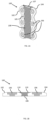
- the sternal repair device 100 shown in Figs. 1A-1C is comprised of left and right plate sections 102, 104 intended to be affixed to a sternum on opposing sides of a sternal osteotomy.
- Each plate section incorporates multiple receiving holes 106 for threaded fixation members, with the two plate sections joined by a central elastomer portion 108 that is coupled to both plate sections to form a unitary device.
- the receiving holes may be threaded in order to engage threads along a portion of the threaded fixation member, such as a bone screw.
- the central elastomer portion comprises a path by which a surgeon can rapidly bisect the sternal repair device using a scalpel should re-resection of the sternum be necessary.
- Fig. 1B shows a cross-sectional view of device 100, where the elastomer 108 is located between and bonded to the plate sections 102, 104 at two interfaces 110, which would prevent substantial contact between the plate sections.
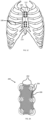
- Fig. 1C shows an anterior view of the chest wall and illustrates a suitable placement of a pair of the sternal repair devices 100 on the sternum 112 as well as an anticipated sternal resection line 114.
- the device is intended to be placed on the sternum after an osteotomy and fixed to the sternum using threaded fixation members, such as bone screws.
- threaded fixation members such as bone screws.
- multiple plates be used to fully secure the sternum, and/or they can be used in conjunction with other fixation devices.
- Fig. 2A shows a perspective view of an alternate embodiment where the sternal repair device 200 comprises a plurality of plate sections 202 that incorporate receiving holes 206 for threaded fixation members joined by a central elastomer portion 208 that is coupled to the plate sections.
- Fig. 2B shows an exploded view where the individual plate sections 202 are shown separated from the elastomer portion 208.
- the plurality of plate sections allow the device to better conform to the topography of the sternum as there is flexibility about both the longitudinal and lateral axes of the device.
- the elastomer still comprises a path by which a surgeon can rapidly bisect the device using a scalpel should re-resection of the sternum be necessary.
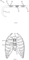
- Fig. 3A shows a perspective view of an alternate embodiment of the sternal repair device 300 that is comprised of two plate sections 302, 304 that have receiving holes 306 for threaded fixation members joined by a central elastomer portion 308 that is coupled to both plate sections.
- Plate section 302 has a plurality of hooks 316 that are intended to engage the edge of the sternum between the ribs to provide additional stability to the device fixation or which can be used in lieu of threaded fixation members on that side of the sternal resection.
- Fig. 3B is a cross-sectional profile view of sternal repair device 300 illustrating hooks 316 on plate section 302.
- FIG. 3C shows an anterior view of the chest wall illustrating placement of a pair of hooked sternal repair devices 300 on the sternum 312 as well as an anticipated sternal resection line 314. While Figs. 3A-3C show devices with two or three hooks, any suitable number of hooks may be used, whether 1, 2, 3, 4, or more as appropriate for the particular application.
- Fig. 4A is a front view of an alternate embodiment of a sternal fixation device 400 similar to the embodiment described in Fig. 1A but where the plate sections 402, 404 extend to couple with the sternum 412 and the rib portion 418 (see Fig. 4B ) with receiving holes 406 for threaded fixation members present along the sternal plate and the extension 403.
- Fig. 4B shows an anterior view of the chest wall illustrating placement of a sternal repair device 400 on the sternum 412 along an anticipated sternal resection line 414 with plate extensions 403 that are fixed to the ribs 418.
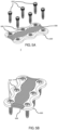
- Fig. 5A shows a view of the sternal fixation device 600 with elastomeric section 608 and threaded fasteners 610 to engage the threaded holes 606 in the plate sections.
- Fig. 5B shows sternal fixation device 600 with the threaded fasteners 610 fully seated in the plate sections.
- the sternal fixation device 600 is intended to be placed on the sternum with the elastomeric section 608 spanning the sternotomy line, and the threaded fixation members 610 are advanced into the holes in the plate sections 602 to rigidly fix the plate to the two halves of the sternum.
- the threaded fixation members shown are intended to be inserted after a hole is pre-drilled into the sternum, but other embodiments may include self-drilling features. If emergency re-entry is required, the surgeon may use a standard surgical scalpel to bisect the elastomer section 608 between the plate sections without the need for additional instrumentation.
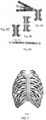
- Figs. 6A, 6B, 6C, and 6D illustrate examples of various embodiments of chest wall repair devices for fixing the sternum and/or a rib segment.
- Fig. 6A illustrates a sterno-costal fixation device
- Fig. 6B illustrates a longitudinal fixation device
- Fig. 6C illustrates a transverse fixation device
- Fig. 6D illustrates a rib fixation / spanning device.
- Fig. 6A also shows the flexibility of the rib segment portion, as evidenced by the background gray elements showing alternative configurations.
- Fig. 7 illustrates the chest wall repair devices of Figs. 7A, 7B, 7C, and 7D in example locations on the chest wall.
Landscapes
- Health & Medical Sciences (AREA)
- Orthopedic Medicine & Surgery (AREA)
- Surgery (AREA)
- Life Sciences & Earth Sciences (AREA)
- Veterinary Medicine (AREA)
- Public Health (AREA)
- General Health & Medical Sciences (AREA)
- Animal Behavior & Ethology (AREA)
- Heart & Thoracic Surgery (AREA)
- Molecular Biology (AREA)
- Medical Informatics (AREA)
- Biomedical Technology (AREA)
- Engineering & Computer Science (AREA)
- Nuclear Medicine, Radiotherapy & Molecular Imaging (AREA)
- Neurology (AREA)
- Chemical & Material Sciences (AREA)
- Vascular Medicine (AREA)
- Epidemiology (AREA)
- Chemical Kinetics & Catalysis (AREA)
- Inorganic Chemistry (AREA)
- Surgical Instruments (AREA)
Description
- The present application claims priority to
U.S. Provisional Patent Application No. 62/360,633, titled "Chest Wall Repair Device for Rapid Reentry," filed July 11, 2016 - Embodiments herein relate to a chest wall repair device, such as for use in stabilization of a sternal osteotomy or for a stabilizing a rib segment.
- The sternum is a bony structure that connects ribs at the front of the chest wall. A sternotomy is a surgical procedure in which the sternum is cut along its longitudinal midline. A sternotomy is performed to gain access to the thoracic cavity for surgery on the heart, lung or other inner organs.
- After a sternotomy has been performed, the divided sternum must be reconnected, or "closed," in a sufficiently stable manner to allow for bony healing of the sternotomy cut. Closure of a sternal osteotomy has traditionally been performed using stainless steel wires that are circumferentially wrapped around the sternum or through the sternum. The circumferential cerclage wires are tensioned to compress the opposing sides of the divided sternum against each other. This traditional cerclage wire technique for sternotomy closure can exhibit healing complications caused by deficient stabilization due to loose or broken wires. Especially in older patients with weaker bone, the thin steel wires can gradually cut through the sternum and loosen. Moreover, circumferential cerclage wiring is time-consuming and complicated, since it requires routing of multiple wires around the back of the sternum.
- To provide a simpler and more durable fixation, metallic plates and clamps for sternal closure have been developed that attach to the front of the sternum. Clinical studies have shown that compared to traditional wire cerclage, repair of a sternal osteotomy with plates provides more stable fixation and leads to better healing, whereby patients experience less pain and require less narcotic medication.
- Moreover, sternal plates and clamps generally do not require surgical access to the back of the sternum, and eliminate the application of circumferential wires or ties. However, their removal typically requires special instruments and extraction of fixation screws, whereby screw heads are frequently overgrown by soft tissue or damaged during implant insertion, complicating screw removal. The speed and ease of implant removal is critical when emergency surgical re-access is required in patients who incur a life-threatening complication. Any delay during emergent re-entry of the thoracic cavity caused by removal of a sternal plate or clamp can therefore be life-threatening, especially in case of heart failure or hemorrhagic bleeding.
- In addition, other aspects of the chest wall may need to be repaired in addition to, or independent of, the sternum, such as caused by injury or other damage or by rib resection.
-
US 2007/0239158 describes plates for use in orthopaedic procedures. The plates have a part that is elastic between two attachment parts. Embodiments in which the elastic part and the attachment parts are separate are described. The plates can be attached to vertebrae by anchors such as bone screws. - Accordingly there is provided a chest wall repair device as detailed in claim 1. Advantageous features are provided in the dependent claims.
- Embodiments will be readily understood by the following detailed description in conjunction with the accompanying drawings and the appended claims. Embodiments are illustrated by way of example and not by way of limitation in the figures of the accompanying drawings.
-
Fig. 1A illustrates a perspective view of one embodiment of a sternal repair device in accordance with embodiments herein; -
Fig. 1B is a cross-sectional view of the device ofFig. 1A , better illustrating the central elastomer portion disposed between the two plate sections in accordance with embodiments herein; -
Fig. 1C is a view of the sternal repair device ofFig. 1A in place on a sternum in accordance with embodiments herein; -
Fig. 2A is a perspective view of another embodiment of a sternal repair device where the screw hole plate sections are discrete elements in accordance with embodiments herein; -
Fig. 2B is an exploded view of the device ofFig. 2A showing the discrete elements separated from the central elastomer portion in accordance with embodiments herein; -
Fig. 3A is a perspective view of another embodiment that incorporates protruding hooks that can wrap over the edge of the sternum in accordance with embodiments herein; -
Fig. 3B is a cross-sectional view of the device ofFig. 3A showing the hooks in accordance with embodiments herein; -
Fig. 3C is a view of the device ofFig. 3A in place on a sternum in accordance with embodiments herein; -
Fig. 4A is a view of another embodiment where the plate sections also engage a portion of the ribs in accordance with embodiments herein; -
Fig. 4B is a view of the device ofFig. 4A in place on a sternum;
; -
Fig. 5A is an exploded view of a sternal fixation device and threaded fasteners in accordance with embodiments herein; -
Fig. 5B is a view of the sternal fixation device ofFig. 5A with the threaded fasteners fully seated in the sternal fixation device in accordance with embodiments herein; -
Figs. 6A, 6B, 6C, and 6D illustrate examples of various embodiments of chest wall repair devices for fixing the sternum and/or a rib segment; and -
Fig. 7 illustrates the chest wall repair devices ofFigs. 6A, 6B, 6C, and 6D in example locations on the chest wall. - With respect to the use of any plural and/or singular terms herein, those having skill in the art can translate from the plural to the singular and/or from the singular to the plural as is appropriate to the context and/or application. The various singular/plural permutations may be expressly set forth herein for sake of clarity.
- To alleviate the clinical challenges noted above, the present disclosure connects two or more plate sections by a central elastomeric portion that can readily be bisected for rapid reentry. Moreover, the invention may also be practiced for fixation of rib fractures or for spanning of rib defects or resections, whereby the central elastomeric portion enables fitting adjacent plate sections to the trajectory of the curved ribs. This elastic connection can furthermore shield the adjacent plate sections from stress and fatigue by allowing elastic flexion.
- In embodiments, the present disclosure addresses the critical need for fast and simple reentry of the chest cavity by provision of a sternal plate with an elastomeric mid-section. This mid-section can readily be cut with the same scalpel used for skin incision. Assuming the sternum has not fully healed after an osteotomy, cutting of the elastomeric mid-section instantly enables separation of the osteotomized sternum and permits emergency access to the thoracic cavity without requiring special instruments.
- According to the present invention, a chest wall repair device for repair of a sternum after sternal osteotomy that allows for rapid resection is provided. Embodiments herein employ a novel technique where a central portion of the device is comprised of an elastomer to allow for rapid resection using a standard surgical scalpel should there be a need to quickly re-enter the chest cavity. Previous attempts have employed strategies such as removable metallic locking pins or thin struts or wires that could be cut to allow for rapid re-entry. Others have used multi-component clamps or polymer ties to achieve removable fixation. However, these methods create additional complexity and require additional instrumentation for resection.
- While embodiments herein may use the term "central" to describe the location of the elastomer, it should be understood that the term does not necessarily mean that the elastomer is at or along one or more center lines of the device. Rather, the term "central" refers to an arrangement whereby elastomer is at least partially flanked by the supporting plate sections.
- Embodiments herein utilize a plate design that is comprised of a plurality of bone fixation sections that are intended to be fixed to the sternum or a rib section and joined by an elastomer section. The bone fixation sections are affixed to bone by threaded fixation members or by geometric constraint such as a hook. The elastomer section is intended to provide a pathway by which a surgeon can cut the plate to separate portions of the plate in order to access and re-open the chest cavity, should the need arise. In embodiments, the presence of elastomer may also provide a degree of flexibility regarding the angle or orientation of the fixation construct on the bone.
- In some embodiments the bone fixation sections may have a feature to engage a spreading instrument to pre-stretch the elastomeric section by increasing the distance between the two bone fixation sections prior to insertion of the threaded fixation members. By pre-stretching the elastomeric section during fixation, compression can be achieved between the sternum or other bone halves after release of the instrument.
- The width of the elastomer section and the elastic modulus of the elastomer material can be varied to affect the amount of motion between the two plate sections. In some embodiments, the elastomer section may be comprised of multiple elastomer materials or grades to achieve different mechanical properties in different regions. Suitable materials for the elastomeric section/portion include silicone or thermoplastic elastomers such as polyurethanes. Should it be desirable to visualize the elastomeric material on the chest x-rays, a radiopaque powder can be added to the elastomer during molding or radiopaque markers such as spheres can be inserted into the elastomer during manufacture. A suitable elastomeric material may have a modulus between 0.1-50 MPa. The elastomeric section should be similar in thickness to the plate, which is typically between 1-4 mm in thickness. The elastomeric section should be between 1-5 mm wide to allow for easy insertion of a scalpel.
- In various embodiments, there are two bone fixation sections each with a plurality of receiving holes. In other embodiments, there may be multiple fixation sections each with a single or plurality of receiving holes.
- In various embodiments, the bone fixation sections are comprised of a metallic biocompatible material such as titanium or stainless steel, but may also be comprised of a polymeric material such as PEEK (polyetheretherketone). In various embodiments, the bone fixation sections may be affixed to only the sternum or to both the ribs as well as the sternum to achieve greater fixation. When used, rib fixation may be on only one side, or may be on both sides of the sternum.
- In various embodiments, the elastomeric section is adhered/secured to the bone fixation sections to form a single piece (unitary) device. Adhesion can be achieved during the molding process by mechanical interlocking of the elastomeric material around features on the surface of the metal parts or chemical adhesion to the surface of the metallic parts. In some cases, a primer can be applied to the metal parts to provide a more chemically favorable surface for bonding of the elastomeric material.
- In various embodiments, features may be provided that restrain the maximal extension of the elastomer or serve to prevent the plate segments from gross separation thus providing a redundancy safety feature in case the elastomer should fail. In embodiments, a central elastomeric portion may contain a connection between the plate sections comprised of one or more elongated polymeric fibers. In other embodiments, at least one plate section may have an extending feature or hook, such as locking
bar 107 inFig. 1A ) that selectively, mechanically interlocks within the opposing plate section and constrains the lateral motion or separation of the plate sections. - In embodiments, a central elastomeric portion may incorporate voids/spaces (such as
void 105 inFig. 1A ) at the elastomer/plate interface that act to prevent propagation of delamination of the elastomer from the plate. - The
sternal repair device 100 shown inFigs. 1A-1C is comprised of left andright plate sections holes 106 for threaded fixation members, with the two plate sections joined by acentral elastomer portion 108 that is coupled to both plate sections to form a unitary device. Although not shown in the illustrated embodiment, the receiving holes may be threaded in order to engage threads along a portion of the threaded fixation member, such as a bone screw. A feature of this embodiment is that the central elastomer portion comprises a path by which a surgeon can rapidly bisect the sternal repair device using a scalpel should re-resection of the sternum be necessary. -
Fig. 1B shows a cross-sectional view ofdevice 100, where theelastomer 108 is located between and bonded to theplate sections interfaces 110, which would prevent substantial contact between the plate sections. -
Fig. 1C shows an anterior view of the chest wall and illustrates a suitable placement of a pair of thesternal repair devices 100 on thesternum 112 as well as an anticipatedsternal resection line 114. The device is intended to be placed on the sternum after an osteotomy and fixed to the sternum using threaded fixation members, such as bone screws. In some cases, multiple plates be used to fully secure the sternum, and/or they can be used in conjunction with other fixation devices. -
Fig. 2A shows a perspective view of an alternate embodiment where thesternal repair device 200 comprises a plurality ofplate sections 202 that incorporate receivingholes 206 for threaded fixation members joined by acentral elastomer portion 208 that is coupled to the plate sections.Fig. 2B shows an exploded view where theindividual plate sections 202 are shown separated from theelastomer portion 208. The plurality of plate sections allow the device to better conform to the topography of the sternum as there is flexibility about both the longitudinal and lateral axes of the device. In this embodiment, the elastomer still comprises a path by which a surgeon can rapidly bisect the device using a scalpel should re-resection of the sternum be necessary. -
Fig. 3A shows a perspective view of an alternate embodiment of thesternal repair device 300 that is comprised of twoplate sections holes 306 for threaded fixation members joined by acentral elastomer portion 308 that is coupled to both plate sections.Plate section 302 has a plurality ofhooks 316 that are intended to engage the edge of the sternum between the ribs to provide additional stability to the device fixation or which can be used in lieu of threaded fixation members on that side of the sternal resection.Fig. 3B is a cross-sectional profile view ofsternal repair device 300 illustrating hooks 316 onplate section 302.Fig. 3C shows an anterior view of the chest wall illustrating placement of a pair of hookedsternal repair devices 300 on thesternum 312 as well as an anticipatedsternal resection line 314. WhileFigs. 3A-3C show devices with two or three hooks, any suitable number of hooks may be used, whether 1, 2, 3, 4, or more as appropriate for the particular application. -
Fig. 4A is a front view of an alternate embodiment of asternal fixation device 400 similar to the embodiment described inFig. 1A but where theplate sections sternum 412 and the rib portion 418 (seeFig. 4B ) with receivingholes 406 for threaded fixation members present along the sternal plate and theextension 403.Fig. 4B shows an anterior view of the chest wall illustrating placement of asternal repair device 400 on thesternum 412 along an anticipatedsternal resection line 414 withplate extensions 403 that are fixed to theribs 418. -
Fig. 5A shows a view of thesternal fixation device 600 withelastomeric section 608 and threadedfasteners 610 to engage the threadedholes 606 in the plate sections.Fig. 5B showssternal fixation device 600 with the threadedfasteners 610 fully seated in the plate sections. Thesternal fixation device 600 is intended to be placed on the sternum with theelastomeric section 608 spanning the sternotomy line, and the threadedfixation members 610 are advanced into the holes in the plate sections 602 to rigidly fix the plate to the two halves of the sternum. The threaded fixation members shown are intended to be inserted after a hole is pre-drilled into the sternum, but other embodiments may include self-drilling features. If emergency re-entry is required, the surgeon may use a standard surgical scalpel to bisect theelastomer section 608 between the plate sections without the need for additional instrumentation. -
Figs. 6A, 6B, 6C, and 6D illustrate examples of various embodiments of chest wall repair devices for fixing the sternum and/or a rib segment.Fig. 6A illustrates a sterno-costal fixation device,Fig. 6B illustrates a longitudinal fixation device,Fig. 6C illustrates a transverse fixation device, andFig. 6D illustrates a rib fixation / spanning device.Fig. 6A also shows the flexibility of the rib segment portion, as evidenced by the background gray elements showing alternative configurations. -
Fig. 7 illustrates the chest wall repair devices of Figs. 7A, 7B, 7C, and 7D in example locations on the chest wall.
Claims (13)
- A chest wall repair device (100, 200, 300) comprising:two or more plate sections (102, 104, 202. 302) with at least a portion of one plate section configured to be affixed to a sternum or rib segment, and at least a portion of another plate section configured to be affixed to a sternum or rib segment on an opposing side of a sternal osteotomy, the plate sections having one or more receiving holes (106, 206, 306, 406) for receiving fixation members, the plate sections having a first surface, a second surface, and a flanking surface extending between the first and second surfaces; anda central elastomeric portion (108, 208, 308,) adhered to the two or more plate sections along the respective flanking surfaces, wherein the two or more plate sections are coupled together by the central elastomeric portion,wherein the first surface of each plate section includes a bevelled edge sloping towards the respective second surface, and the central elastomeric portion (108, 208, 308) is adhered to the flanking surface and the bevelled edge of each plate section.
- The device of claim 1 wherein the two or more plate sections are comprised of titanium or stainless steel.
- The device of claim 1 wherein the plate sections are comprised of a polymeric material.
- The device of claim 1 wherein at least one of the plate sections incorporates at least one threaded receiving hole.
- The device of claim 1 wherein at least one of the plate sections incorporates at least one non-threaded receiving hole.
- The device of claim 1 wherein at least one of the plate sections incorporates a hook (316) configured to engage an edge of the sternum.
- The device of claim 1 wherein the central elastomeric portion is comprised of silicone, or wherein the central elastomeric portion has a modulus between 0.1-50 MPa.
- The device of claim 1 wherein the central elastomeric portion contains radio-opaque spheres, particles, or wires to allow for visualization under X-ray.
- The device of claim 1 wherein the central elastomeric portion is comprised of multiple grades or stiffnesses to create regional variations in mechanical properties.
- The device of claim 1 wherein features are present to allow for stretching of the device prior to fixation to the sternum in order to apply compression to the resection after release.
- The device of claim 1, wherein the central elastomeric portion comprises one or more elongated polymeric fibers.
- The device of claim 1, wherein the central elastomeric portion has at least one void at an interface between the elastomeric portion and one of the two or more plate sections to prevent propagation of delamination of the elastomeric portion from the plate section.
- The device of claim 1, wherein at least one of the two or more plate sections has an extending feature that mechanically interlocks with an opposing plate section to constrain lateral motion.
Applications Claiming Priority (2)
| Application Number | Priority Date | Filing Date | Title |
|---|---|---|---|
| US201662360633P | 2016-07-11 | 2016-07-11 | |
| PCT/US2017/041573 WO2018013594A1 (en) | 2016-07-11 | 2017-07-11 | Chest wall repair device |
Publications (3)
| Publication Number | Publication Date |
|---|---|
| EP3481314A1 EP3481314A1 (en) | 2019-05-15 |
| EP3481314A4 EP3481314A4 (en) | 2020-04-22 |
| EP3481314B1 true EP3481314B1 (en) | 2024-10-16 |
Family
ID=60952699
Family Applications (1)
| Application Number | Title | Priority Date | Filing Date |
|---|---|---|---|
| EP17828328.9A Active EP3481314B1 (en) | 2016-07-11 | 2017-07-11 | Chest wall repair device |
Country Status (5)
| Country | Link |
|---|---|
| US (2) | US20190374267A1 (en) |
| EP (1) | EP3481314B1 (en) |
| AU (2) | AU2017296286B9 (en) |
| CA (1) | CA3030168C (en) |
| WO (1) | WO2018013594A1 (en) |
Families Citing this family (14)
| Publication number | Priority date | Publication date | Assignee | Title |
|---|---|---|---|---|
| WO2019246138A1 (en) * | 2018-06-18 | 2019-12-26 | Revelation Plating, Llc | Flexible guide for application of bone plates |
| US11356033B2 (en) | 2018-07-04 | 2022-06-07 | Siemens Energy Global GmbH & Co. KG | Modular multi-point converter with modular storage units |
| EP4385433B1 (en) * | 2019-03-18 | 2026-01-14 | GLW, Inc. | Hybrid bone plate |
| CO2020003879A1 (en) * | 2020-03-30 | 2021-04-08 | Techfit Digital Surgery Inc | One-piece sternum replacement implant |
| CN111529035A (en) * | 2020-05-28 | 2020-08-14 | 四川大学华西医院 | Anterior cervical vertebrae degeneration prevention buffer device |
| US11331130B1 (en) * | 2020-12-10 | 2022-05-17 | DePuy Synthes Products, Inc. | Sternal closure systems and methods of use thereof |
| US11771481B2 (en) * | 2021-03-08 | 2023-10-03 | Zimmer Biomet CMF and Thoracic, LLC | Sternal plates and methods of use |
| FR3120512B1 (en) * | 2021-03-12 | 2023-05-12 | I Ceram | STERNAL RECONSTRUCTION INTERFACE |
| EP4319666B1 (en) | 2021-04-09 | 2025-06-11 | GLW, Inc. | Hybrid bone plates and associated manufacturing processes |
| US12605193B2 (en) | 2022-12-20 | 2026-04-21 | Adam J. Hansen | Minimally invasive sternal fracture repair |
| WO2024186931A1 (en) | 2023-03-06 | 2024-09-12 | Zimmer Biomet CMF and Thoracic, LLC | Pectus bar and stabilizer devices |
| USD1120328S1 (en) | 2024-04-30 | 2026-03-24 | DePuy Synthes Products, Inc. | Bone plate |
| USD1116113S1 (en) | 2024-04-30 | 2026-03-03 | DePuy Synthes Products, Inc. | Bone plate |
| US20260026853A1 (en) * | 2024-07-23 | 2026-01-29 | Jeko Metodiev Madjarov | Device for chest wall reconstruction |
Family Cites Families (18)
| Publication number | Priority date | Publication date | Assignee | Title |
|---|---|---|---|---|
| US6620196B1 (en) * | 2000-08-30 | 2003-09-16 | Sdgi Holdings, Inc. | Intervertebral disc nucleus implants and methods |
| US6872210B2 (en) * | 2001-02-23 | 2005-03-29 | James P. Hearn | Sternum fixation device |
| US20030083694A1 (en) * | 2001-10-31 | 2003-05-01 | Miller Archibald S. | Method and apparatus for closing a severed sternum |
| US7169150B2 (en) * | 2003-04-25 | 2007-01-30 | Warsaw Orthopedic, Inc. | Non-metallic orthopedic plate |
| DE10326690B4 (en) * | 2003-06-04 | 2005-04-28 | Aesculap Ag & Co Kg | Sternum closure |
| US20070239158A1 (en) * | 2006-04-10 | 2007-10-11 | Sdgi Holdings, Inc. | Elastic plates for spinal fixation or stabilization |
| US8226693B2 (en) * | 2006-06-16 | 2012-07-24 | Reimels William J | Bone bridge providing dynamic compression on bone fractures |
| US20080154312A1 (en) * | 2006-12-12 | 2008-06-26 | Dennis Colleran | Active settling plate with elastomeric members and method of use |
| ITTO20080465A1 (en) * | 2008-06-16 | 2008-09-15 | Ntplast S R L | ELASTIC FIXING DEVICE FOR THE CLOSURE OF THE EXTERIOR AFTER A STERNOTOMY, PROCEDURE AND INSTRUMENTS FOR THE APPLICATION OF SUCH DEVICE. |
| US20130060288A1 (en) * | 2009-06-23 | 2013-03-07 | Nuvasive, Inc. | Methods and instrumentation for orthopedic surgery |
| US8758417B2 (en) * | 2009-08-05 | 2014-06-24 | Charles A. Anderson | Adjustable sternal clamp array |
| WO2011082152A1 (en) * | 2009-12-30 | 2011-07-07 | Synthes Usa, Llc | Intergrated multi-material implants and methods of manufacture |
| WO2013130978A2 (en) * | 2012-03-01 | 2013-09-06 | Solana Surgical, Llc | Surgical staple |
| JP2014140467A (en) | 2013-01-23 | 2014-08-07 | Tatsuta Electric Wire & Cable Co Ltd | Drip speed measuring instrument |
| EP3498207B1 (en) * | 2013-03-15 | 2026-02-25 | Biomet Microfixation, Llc | Sternal closure cerclage, plate implant and instrumentation |
| US10433889B2 (en) * | 2013-07-11 | 2019-10-08 | Stryker European Holdings I, Llc | Fixation assembly with a flexible elongated member for securing parts of a sternum |
| US10026015B2 (en) * | 2014-04-01 | 2018-07-17 | Case Western Reserve University | Imaging control to facilitate tracking objects and/or perform real-time intervention |
| US9745849B2 (en) | 2015-06-26 | 2017-08-29 | General Electric Company | Methods for treating field operated components |
-
2017
- 2017-07-11 WO PCT/US2017/041573 patent/WO2018013594A1/en not_active Ceased
- 2017-07-11 US US16/315,107 patent/US20190374267A1/en not_active Abandoned
- 2017-07-11 AU AU2017296286A patent/AU2017296286B9/en active Active
- 2017-07-11 CA CA3030168A patent/CA3030168C/en active Active
- 2017-07-11 EP EP17828328.9A patent/EP3481314B1/en active Active
-
2020
- 2020-11-27 AU AU2020277265A patent/AU2020277265B2/en active Active
-
2021
- 2021-05-04 US US17/307,665 patent/US11576706B2/en active Active
Also Published As
| Publication number | Publication date |
|---|---|
| AU2020277265A1 (en) | 2020-12-24 |
| US11576706B2 (en) | 2023-02-14 |
| US20190374267A1 (en) | 2019-12-12 |
| CA3030168C (en) | 2022-02-22 |
| EP3481314A4 (en) | 2020-04-22 |
| AU2020277265B2 (en) | 2022-05-19 |
| AU2017296286B9 (en) | 2021-07-29 |
| AU2017296286A1 (en) | 2019-02-21 |
| WO2018013594A1 (en) | 2018-01-18 |
| AU2017296286B2 (en) | 2020-08-27 |
| EP3481314A1 (en) | 2019-05-15 |
| US20210251671A1 (en) | 2021-08-19 |
| CA3030168A1 (en) | 2018-01-18 |
Similar Documents
| Publication | Publication Date | Title |
|---|---|---|
| AU2020277265B2 (en) | Chest wall repair device | |
| US12433651B2 (en) | Sternum fixation device and method | |
| JP5805624B2 (en) | Multiple screw | |
| US10433889B2 (en) | Fixation assembly with a flexible elongated member for securing parts of a sternum | |
| US10154864B2 (en) | Sternum fixation device and method | |
| US10022170B2 (en) | Osteotomy device, in particular for performing extreme SCARF osteotomy in the treatment of severe Hallux Valgus | |
| AU2015320378B2 (en) | Implant devices and systems for stabilized fixation of bone and soft tissue | |
| US20170303978A1 (en) | Rigid fixation systems for cardiothoracic fixation | |
| US9968389B2 (en) | Fracture plating | |
| AU2016204989A1 (en) | Extensions for spinal anchors | |
| JP6437545B2 (en) | Monocortical pin fixture | |
| US11317903B2 (en) | Implant devices and systems for stabilized fixation of bone and soft tissue | |
| US20250160855A1 (en) | Intramedullary nail fixation guides, devices, and methods of use | |
| US9918741B2 (en) | Anchoring group for external fixator | |
| EP1635721A2 (en) | Orthopedic clamps | |
| US20240090925A1 (en) | Hook-Spring Plate for Growth Modulation of Immature Rib to Correct Early Onset Scoliosis | |
| US20260026853A1 (en) | Device for chest wall reconstruction |
Legal Events
| Date | Code | Title | Description |
|---|---|---|---|
| STAA | Information on the status of an ep patent application or granted ep patent |
Free format text: STATUS: THE INTERNATIONAL PUBLICATION HAS BEEN MADE |
|
| PUAI | Public reference made under article 153(3) epc to a published international application that has entered the european phase |
Free format text: ORIGINAL CODE: 0009012 |
|
| STAA | Information on the status of an ep patent application or granted ep patent |
Free format text: STATUS: REQUEST FOR EXAMINATION WAS MADE |
|
| 17P | Request for examination filed |
Effective date: 20190308 |
|
| AK | Designated contracting states |
Kind code of ref document: A1 Designated state(s): AL AT BE BG CH CY CZ DE DK EE ES FI FR GB GR HR HU IE IS IT LI LT LU LV MC MK MT NL NO PL PT RO RS SE SI SK SM TR |
|
| AX | Request for extension of the european patent |
Extension state: BA ME |
|
| RIN1 | Information on inventor provided before grant (corrected) |
Inventor name: MADEY, STEVEN |
|
| DAV | Request for validation of the european patent (deleted) | ||
| DAX | Request for extension of the european patent (deleted) | ||
| A4 | Supplementary search report drawn up and despatched |
Effective date: 20200319 |
|
| RIC1 | Information provided on ipc code assigned before grant |
Ipc: A61L 31/06 20060101ALI20200313BHEP Ipc: A61B 17/86 20060101ALI20200313BHEP Ipc: A61B 17/84 20060101ALI20200313BHEP Ipc: A61B 17/80 20060101AFI20200313BHEP Ipc: A61L 31/02 20060101ALI20200313BHEP Ipc: A61B 17/82 20060101ALI20200313BHEP |
|
| STAA | Information on the status of an ep patent application or granted ep patent |
Free format text: STATUS: EXAMINATION IS IN PROGRESS |
|
| 17Q | First examination report despatched |
Effective date: 20211108 |
|
| GRAP | Despatch of communication of intention to grant a patent |
Free format text: ORIGINAL CODE: EPIDOSNIGR1 |
|
| STAA | Information on the status of an ep patent application or granted ep patent |
Free format text: STATUS: GRANT OF PATENT IS INTENDED |
|
| INTG | Intention to grant announced |
Effective date: 20240513 |
|
| GRAS | Grant fee paid |
Free format text: ORIGINAL CODE: EPIDOSNIGR3 |
|
| GRAA | (expected) grant |
Free format text: ORIGINAL CODE: 0009210 |
|
| STAA | Information on the status of an ep patent application or granted ep patent |
Free format text: STATUS: THE PATENT HAS BEEN GRANTED |
|
| RAP1 | Party data changed (applicant data changed or rights of an application transferred) |
Owner name: REVELATION PLATING, LLC |
|
| AK | Designated contracting states |
Kind code of ref document: B1 Designated state(s): AL AT BE BG CH CY CZ DE DK EE ES FI FR GB GR HR HU IE IS IT LI LT LU LV MC MK MT NL NO PL PT RO RS SE SI SK SM TR |
|
| REG | Reference to a national code |
Ref country code: GB Ref legal event code: FG4D |
|
| REG | Reference to a national code |
Ref country code: DE Ref legal event code: R096 Ref document number: 602017085555 Country of ref document: DE Ref country code: CH Ref legal event code: EP |
|
| REG | Reference to a national code |
Ref country code: IE Ref legal event code: FG4D |
|
| REG | Reference to a national code |
Ref country code: LT Ref legal event code: MG9D |
|
| REG | Reference to a national code |
Ref country code: NL Ref legal event code: MP Effective date: 20241016 |
|
| REG | Reference to a national code |
Ref country code: AT Ref legal event code: MK05 Ref document number: 1732293 Country of ref document: AT Kind code of ref document: T Effective date: 20241016 |
|
| PG25 | Lapsed in a contracting state [announced via postgrant information from national office to epo] |
Ref country code: NL Free format text: LAPSE BECAUSE OF FAILURE TO SUBMIT A TRANSLATION OF THE DESCRIPTION OR TO PAY THE FEE WITHIN THE PRESCRIBED TIME-LIMIT Effective date: 20241016 |
|
| PG25 | Lapsed in a contracting state [announced via postgrant information from national office to epo] |
Ref country code: NL Free format text: LAPSE BECAUSE OF FAILURE TO SUBMIT A TRANSLATION OF THE DESCRIPTION OR TO PAY THE FEE WITHIN THE PRESCRIBED TIME-LIMIT Effective date: 20241016 |
|
| PG25 | Lapsed in a contracting state [announced via postgrant information from national office to epo] |
Ref country code: IS Free format text: LAPSE BECAUSE OF FAILURE TO SUBMIT A TRANSLATION OF THE DESCRIPTION OR TO PAY THE FEE WITHIN THE PRESCRIBED TIME-LIMIT Effective date: 20250216 Ref country code: PT Free format text: LAPSE BECAUSE OF FAILURE TO SUBMIT A TRANSLATION OF THE DESCRIPTION OR TO PAY THE FEE WITHIN THE PRESCRIBED TIME-LIMIT Effective date: 20250217 Ref country code: HR Free format text: LAPSE BECAUSE OF FAILURE TO SUBMIT A TRANSLATION OF THE DESCRIPTION OR TO PAY THE FEE WITHIN THE PRESCRIBED TIME-LIMIT Effective date: 20241016 |
|
| PG25 | Lapsed in a contracting state [announced via postgrant information from national office to epo] |
Ref country code: FI Free format text: LAPSE BECAUSE OF FAILURE TO SUBMIT A TRANSLATION OF THE DESCRIPTION OR TO PAY THE FEE WITHIN THE PRESCRIBED TIME-LIMIT Effective date: 20241016 |
|
| PG25 | Lapsed in a contracting state [announced via postgrant information from national office to epo] |
Ref country code: BG Free format text: LAPSE BECAUSE OF FAILURE TO SUBMIT A TRANSLATION OF THE DESCRIPTION OR TO PAY THE FEE WITHIN THE PRESCRIBED TIME-LIMIT Effective date: 20241016 |
|
| PG25 | Lapsed in a contracting state [announced via postgrant information from national office to epo] |
Ref country code: ES Free format text: LAPSE BECAUSE OF FAILURE TO SUBMIT A TRANSLATION OF THE DESCRIPTION OR TO PAY THE FEE WITHIN THE PRESCRIBED TIME-LIMIT Effective date: 20241016 |
|
| PG25 | Lapsed in a contracting state [announced via postgrant information from national office to epo] |
Ref country code: NO Free format text: LAPSE BECAUSE OF FAILURE TO SUBMIT A TRANSLATION OF THE DESCRIPTION OR TO PAY THE FEE WITHIN THE PRESCRIBED TIME-LIMIT Effective date: 20250116 |
|
| PG25 | Lapsed in a contracting state [announced via postgrant information from national office to epo] |
Ref country code: LV Free format text: LAPSE BECAUSE OF FAILURE TO SUBMIT A TRANSLATION OF THE DESCRIPTION OR TO PAY THE FEE WITHIN THE PRESCRIBED TIME-LIMIT Effective date: 20241016 Ref country code: GR Free format text: LAPSE BECAUSE OF FAILURE TO SUBMIT A TRANSLATION OF THE DESCRIPTION OR TO PAY THE FEE WITHIN THE PRESCRIBED TIME-LIMIT Effective date: 20250117 Ref country code: AT Free format text: LAPSE BECAUSE OF FAILURE TO SUBMIT A TRANSLATION OF THE DESCRIPTION OR TO PAY THE FEE WITHIN THE PRESCRIBED TIME-LIMIT Effective date: 20241016 |
|
| PG25 | Lapsed in a contracting state [announced via postgrant information from national office to epo] |
Ref country code: PL Free format text: LAPSE BECAUSE OF FAILURE TO SUBMIT A TRANSLATION OF THE DESCRIPTION OR TO PAY THE FEE WITHIN THE PRESCRIBED TIME-LIMIT Effective date: 20241016 |
|
| PG25 | Lapsed in a contracting state [announced via postgrant information from national office to epo] |
Ref country code: RS Free format text: LAPSE BECAUSE OF FAILURE TO SUBMIT A TRANSLATION OF THE DESCRIPTION OR TO PAY THE FEE WITHIN THE PRESCRIBED TIME-LIMIT Effective date: 20250116 |
|
| PG25 | Lapsed in a contracting state [announced via postgrant information from national office to epo] |
Ref country code: SM Free format text: LAPSE BECAUSE OF FAILURE TO SUBMIT A TRANSLATION OF THE DESCRIPTION OR TO PAY THE FEE WITHIN THE PRESCRIBED TIME-LIMIT Effective date: 20241016 |
|
| PG25 | Lapsed in a contracting state [announced via postgrant information from national office to epo] |
Ref country code: DK Free format text: LAPSE BECAUSE OF FAILURE TO SUBMIT A TRANSLATION OF THE DESCRIPTION OR TO PAY THE FEE WITHIN THE PRESCRIBED TIME-LIMIT Effective date: 20241016 |
|
| REG | Reference to a national code |
Ref country code: DE Ref legal event code: R097 Ref document number: 602017085555 Country of ref document: DE |
|
| PG25 | Lapsed in a contracting state [announced via postgrant information from national office to epo] |
Ref country code: EE Free format text: LAPSE BECAUSE OF FAILURE TO SUBMIT A TRANSLATION OF THE DESCRIPTION OR TO PAY THE FEE WITHIN THE PRESCRIBED TIME-LIMIT Effective date: 20241016 |
|
| PG25 | Lapsed in a contracting state [announced via postgrant information from national office to epo] |
Ref country code: RO Free format text: LAPSE BECAUSE OF FAILURE TO SUBMIT A TRANSLATION OF THE DESCRIPTION OR TO PAY THE FEE WITHIN THE PRESCRIBED TIME-LIMIT Effective date: 20241016 |
|
| PG25 | Lapsed in a contracting state [announced via postgrant information from national office to epo] |
Ref country code: SK Free format text: LAPSE BECAUSE OF FAILURE TO SUBMIT A TRANSLATION OF THE DESCRIPTION OR TO PAY THE FEE WITHIN THE PRESCRIBED TIME-LIMIT Effective date: 20241016 |
|
| PG25 | Lapsed in a contracting state [announced via postgrant information from national office to epo] |
Ref country code: CZ Free format text: LAPSE BECAUSE OF FAILURE TO SUBMIT A TRANSLATION OF THE DESCRIPTION OR TO PAY THE FEE WITHIN THE PRESCRIBED TIME-LIMIT Effective date: 20241016 |
|
| PG25 | Lapsed in a contracting state [announced via postgrant information from national office to epo] |
Ref country code: IT Free format text: LAPSE BECAUSE OF FAILURE TO SUBMIT A TRANSLATION OF THE DESCRIPTION OR TO PAY THE FEE WITHIN THE PRESCRIBED TIME-LIMIT Effective date: 20241016 |
|
| PLBE | No opposition filed within time limit |
Free format text: ORIGINAL CODE: 0009261 |
|
| STAA | Information on the status of an ep patent application or granted ep patent |
Free format text: STATUS: NO OPPOSITION FILED WITHIN TIME LIMIT |
|
| PG25 | Lapsed in a contracting state [announced via postgrant information from national office to epo] |
Ref country code: SE Free format text: LAPSE BECAUSE OF FAILURE TO SUBMIT A TRANSLATION OF THE DESCRIPTION OR TO PAY THE FEE WITHIN THE PRESCRIBED TIME-LIMIT Effective date: 20241016 |
|
| 26N | No opposition filed |
Effective date: 20250717 |
|
| PGFP | Annual fee paid to national office [announced via postgrant information from national office to epo] |
Ref country code: DE Payment date: 20250708 Year of fee payment: 9 |
|
| PGFP | Annual fee paid to national office [announced via postgrant information from national office to epo] |
Ref country code: GB Payment date: 20250710 Year of fee payment: 9 |
|
| PGFP | Annual fee paid to national office [announced via postgrant information from national office to epo] |
Ref country code: FR Payment date: 20250708 Year of fee payment: 9 |
|
| REG | Reference to a national code |
Ref country code: CH Ref legal event code: H13 Free format text: ST27 STATUS EVENT CODE: U-0-0-H10-H13 (AS PROVIDED BY THE NATIONAL OFFICE) Effective date: 20260224 |
|
| PG25 | Lapsed in a contracting state [announced via postgrant information from national office to epo] |
Ref country code: LU Free format text: LAPSE BECAUSE OF NON-PAYMENT OF DUE FEES Effective date: 20250711 |
|
| REG | Reference to a national code |
Ref country code: BE Ref legal event code: MM Effective date: 20250731 |
|
| PG25 | Lapsed in a contracting state [announced via postgrant information from national office to epo] |
Ref country code: BE Free format text: LAPSE BECAUSE OF NON-PAYMENT OF DUE FEES Effective date: 20250731 |
|
| PG25 | Lapsed in a contracting state [announced via postgrant information from national office to epo] |
Ref country code: CH Free format text: LAPSE BECAUSE OF NON-PAYMENT OF DUE FEES Effective date: 20250731 |