EP3481204B1 - Verfahren zur bestimmung der feuchtigkeit innerhalb eines garraumes eines gargeräts sowie gargerät - Google Patents
Verfahren zur bestimmung der feuchtigkeit innerhalb eines garraumes eines gargeräts sowie gargerät Download PDFInfo
- Publication number
- EP3481204B1 EP3481204B1 EP17737587.0A EP17737587A EP3481204B1 EP 3481204 B1 EP3481204 B1 EP 3481204B1 EP 17737587 A EP17737587 A EP 17737587A EP 3481204 B1 EP3481204 B1 EP 3481204B1
- Authority
- EP
- European Patent Office
- Prior art keywords
- cooking device
- cooking
- chamber
- resonance chamber
- cavity
- Prior art date
- Legal status (The legal status is an assumption and is not a legal conclusion. Google has not performed a legal analysis and makes no representation as to the accuracy of the status listed.)
- Active
Links
Images



Classifications
-
- A—HUMAN NECESSITIES
- A21—BAKING; EDIBLE DOUGHS
- A21B—BAKERS' OVENS; MACHINES OR EQUIPMENT FOR BAKING
- A21B3/00—Parts or accessories of ovens
- A21B3/04—Air-treatment devices for ovens, e.g. regulating humidity
-
- G—PHYSICS
- G01—MEASURING; TESTING
- G01N—INVESTIGATING OR ANALYSING MATERIALS BY DETERMINING THEIR CHEMICAL OR PHYSICAL PROPERTIES
- G01N29/00—Investigating or analysing materials by the use of ultrasonic, sonic or infrasonic waves; Visualisation of the interior of objects by transmitting ultrasonic or sonic waves through the object
- G01N29/02—Analysing fluids
- G01N29/024—Analysing fluids by measuring propagation velocity or propagation time of acoustic waves
-
- F—MECHANICAL ENGINEERING; LIGHTING; HEATING; WEAPONS; BLASTING
- F24—HEATING; RANGES; VENTILATING
- F24C—DOMESTIC STOVES OR RANGES ; DETAILS OF DOMESTIC STOVES OR RANGES, OF GENERAL APPLICATION
- F24C15/00—Details
- F24C15/32—Arrangements of ducts for hot gases, e.g. in or around baking ovens
- F24C15/322—Arrangements of ducts for hot gases, e.g. in or around baking ovens with forced circulation
- F24C15/327—Arrangements of ducts for hot gases, e.g. in or around baking ovens with forced circulation with air moisturising
-
- F—MECHANICAL ENGINEERING; LIGHTING; HEATING; WEAPONS; BLASTING
- F24—HEATING; RANGES; VENTILATING
- F24C—DOMESTIC STOVES OR RANGES ; DETAILS OF DOMESTIC STOVES OR RANGES, OF GENERAL APPLICATION
- F24C7/00—Stoves or ranges heated by electric energy
- F24C7/08—Arrangement or mounting of control or safety devices
-
- G—PHYSICS
- G01—MEASURING; TESTING
- G01N—INVESTIGATING OR ANALYSING MATERIALS BY DETERMINING THEIR CHEMICAL OR PHYSICAL PROPERTIES
- G01N29/00—Investigating or analysing materials by the use of ultrasonic, sonic or infrasonic waves; Visualisation of the interior of objects by transmitting ultrasonic or sonic waves through the object
- G01N29/02—Analysing fluids
- G01N29/036—Analysing fluids by measuring frequency or resonance of acoustic waves
-
- G—PHYSICS
- G01—MEASURING; TESTING
- G01N—INVESTIGATING OR ANALYSING MATERIALS BY DETERMINING THEIR CHEMICAL OR PHYSICAL PROPERTIES
- G01N29/00—Investigating or analysing materials by the use of ultrasonic, sonic or infrasonic waves; Visualisation of the interior of objects by transmitting ultrasonic or sonic waves through the object
- G01N29/22—Details, e.g. general constructional or apparatus details
- G01N29/32—Arrangements for suppressing undesired influences, e.g. temperature or pressure variations, compensating for signal noise
- G01N29/326—Arrangements for suppressing undesired influences, e.g. temperature or pressure variations, compensating for signal noise compensating for temperature variations
-
- G—PHYSICS
- G01—MEASURING; TESTING
- G01N—INVESTIGATING OR ANALYSING MATERIALS BY DETERMINING THEIR CHEMICAL OR PHYSICAL PROPERTIES
- G01N29/00—Investigating or analysing materials by the use of ultrasonic, sonic or infrasonic waves; Visualisation of the interior of objects by transmitting ultrasonic or sonic waves through the object
- G01N29/44—Processing the detected response signal, e.g. electronic circuits specially adapted therefor
- G01N29/46—Processing the detected response signal, e.g. electronic circuits specially adapted therefor by spectral analysis, e.g. Fourier analysis or wavelet analysis
Definitions
- the invention relates to a method for determining the humidity inside a cooking chamber and a cooking appliance for this purpose.
- Such cooking devices can be designed as so-called combi-steamers, ie as cooking devices in which the food to be cooked is cooked with hot air and/or steam.
- combi-steamers ie as cooking devices in which the food to be cooked is cooked with hot air and/or steam.
- the moisture in the cooking chamber i. H. to know the water content of the atmosphere in the cooking chamber of the cooking appliance.
- the EP 1 300 079 A2 discloses a cooking appliance with a resonance chamber for determining the humidity in the cooking chamber.
- the resonant frequency of the resonant chamber is excited by means of a loudspeaker, with the frequency at which the loudspeaker is operated being continuously readjusted to the changing resonant frequency.
- the signals or vibrations in the resonance chamber are generated by a broadband sound source.
- the vibrations in the resonance space are natural vibrations of the resonance space, i. H. Standing waves of the basic order or higher orders in the resonant chamber, also called the fundamental or overtones.
- the humidity is determined by determining or indirectly measuring the speed of sound in the resonance chamber, the speed of sound in the resonance chamber being dependent on the temperature and the composition of the atmosphere in the resonance chamber.
- the frequencies of the vibrations excited in the resonance chamber in particular the frequency of the fundamental vibration, are determined, from which the speed of sound can be deduced using the known wavelength of the fundamental vibration.
- the frequency of the fundamental can be determined very precisely because the determined frequencies of the overtones can be used to correct the determined frequency value of the fundamental.
- the determination of the fundamental frequency and thus the determination of the humidity is independent of the activation of the sound source, and a complicated and phase-correct coupling of the sound from the sound generator to the resonant chamber is omitted, since the broadband excitation is certain to cause natural oscillations, ie resonances in the resonant chamber. In this way, the moisture can be precisely determined using simple means that are already partly present in the cooking appliance.
- the temperature value is, for example, a measured value from a temperature sensor in the resonance chamber or in the cooking chamber.
- the temperature value is another value, which the control unit can use to infer the temperature in the resonance chamber, for example the target temperature of the heating device of the cooking appliance. In this way, the temperature in the resonance chamber can be determined very precisely.
- control unit determines the frequency spectrum by means of Fourier analysis and/or by determining the correlation function, as a result of which the frequency spectrum can be determined reliably.
- a cooking appliance with a cooking chamber, a resonance chamber, a sound generator that is designed to generate a broadband signal in the resonance chamber, a microphone assigned to the resonance chamber, a temperature value unit that uses a temperature value that depends on the temperature of the atmosphere in the cooking appliance signal, and a control unit to which the microphone and the temperature value unit are connected, wherein the control unit contains a module for spectral analysis, in particular a Fourier analysis and/or a correlation function module, and wherein the control unit is designed and set up to use the Microphone received signals to determine a frequency spectrum of the acoustic signal present in the resonance chamber independently of the control of the sound generator and based on the fundamental frequency of the frequency spectrum or overtones of the frequency spectrum from which the fundamental frequency can be determined, the speed of sound within Hal b of the resonance chamber and using the temperature value and the speed of sound to determine the humidity within the cooking chamber according to an inventive method.
- the control unit is able to precisely determine the frequency spectrum of the vibrations occurring
- the cooking appliance preferably has a fan wheel, with the fan wheel representing the sound generator. There are therefore no further components required in addition to the components already present in the cooking appliance in order to generate the required sound.
- the cooking appliance can have a loudspeaker, with the loudspeaker representing the sound generator, so that the humidity can also be determined independently of the operation of the cooking appliance, in particular independently of the operation of the fan wheel.
- the cooking appliance has a loudspeaker control which can control the loudspeaker in such a way that the loudspeaker emits noise or carries out a frequency sweep.
- the noise can be white noise.
- the loudspeaker In a frequency sweep, the loudspeaker generates an oscillation of a frequency, with the frequency of this oscillation running through a frequency range over a specific time interval. In this way, too, an ultimately broadband signal is generated.
- the cooking chamber of the cooking appliance is the resonance chamber, which means that no additional component is required to implement the resonance chamber.
- the resonance chamber lies within a resonator which is open to the cooking chamber of the cooking appliance.
- the resonator is a geometrically clearly defined space that is comparatively small compared to the cooking space, for example in the form of a cylinder or a rectangular cavity. In this way, the dimensions and geometries of the resonance space can be freely selected.
- the resonator is arranged in the cooking chamber of the cooking appliance.
- the cooking chamber can be thermally and acoustically coupled to the resonator very well.
- the resonator can be open at its lower end and/or arranged in such a way that the resonator is also cleaned by the washing liquor of the cooking appliance when the cooking chamber of the cooking appliance is being cleaned.
- the temperature sensor can also be arranged on the resonator.
- the resonator is preferably designed as a tube, which means that the resonator can be produced easily and inexpensively.
- the tube is 20 cm long and/or has an inner diameter of 1.5 cm to 2 cm.
- the tube can also be open on one or both sides and/or is arranged vertically in the cooking chamber. It is also conceivable that at least one opening is provided in the wall of the tube in order to influence the vibrations occurring in the resonator.
- the resonator has a first tube and a second tube acoustically coupled to the first tube and/or a cavity acoustically coupled to the first tube.
- the tubes can preferably be of different lengths and/or have different diameters.
- the tubes can be parallel to each other. The fact that several acoustically coupled volumes are created by the two tubes or by the first tube and the cavity gives the frequency or resonance spectrum of the resonator a characteristic structure that offers a simple way of distinguishing it from acoustic sources of interference.
- the second tube and/or the cavity extend from the first tube, which guarantees good acoustic coupling.
- the cooking appliance has a cavity that is acoustically coupled to the resonance chamber at a coupling point, with the microphone being provided in the cavity.
- the microphone can be placed outside of the resonance chamber and the cooking chamber.
- the cavity can be formed by a further pipe or hose. The diameter of the hose or tube differs from the diameter of the resonator at the coupling point to create an impedance jump at the coupling point, thereby reducing the coupling between the cavity and the resonator to decouple less energy from the resonator.
- the length of the cavity can also be chosen so that the resonant frequency of the system of resonance space and cavity differs significantly from the resonance frequency of the resonance space, so that in the frequency spectrum there is a clear distinction between the vibrations in the resonance space alone and any vibrations that may occur in the system of cavity and resonance space can be.
- the cavity can be coupled directly to both inner volumes of the tubes. It is also conceivable in this case that two cavities are provided, each with a microphone, which are each coupled to one of the tubes.
- the cavity includes a membrane placed in the interface to protect the microphone from water vapor, dirt, and heat.
- the membrane can have an embossing and/or be shaped in such a way that the restoring forces against deflection of the membrane are reduced or not increased by installation, e.g. with a press fit.
- a step for attaching the membrane can be provided in the wall of the cavity.
- the membrane can have an embossing of at least one concentric ring.
- the cavity can have a vibration-damping or vibration-absorbing shape at its end facing away from the coupling point, in particular tapering towards the end, in particular tapering to a point, so that vibrations in the cavity are damped and no standing waves can form in the cavity.
- the cavity can also be provided with sound-absorbing material, in particular at its end facing away from the coupling point, so that vibrations in the cavity are not reflected.
- the cavity widens in a funnel shape towards the coupling point.
- the microphone is provided in the resonance chamber, as a result of which the amplitudes of the vibrations in the resonance chamber can be measured directly and precisely.
- the microphone or the coupling point is preferably arranged in the area of the maximum of the sound pressure of one or more of the natural vibrations of the resonance chamber, whereby a good coupling of the microphone to the resonator is achieved, so that the quality of the measurement can be improved.
- Other positions of the microphone or the coupling point that have a favorable coupling are also conceivable.
- a possible position of the microphone or the coupling point is the center of the tube in relation to its longitudinal axis.
- the microphone or the coupling point is preferably located between 10% and 15%, in particular approximately 13%, of the length of the tube from the end of the tube in the longitudinal direction.
- the temperature value unit is provided on or in the resonator, in particular in the area of the coupling point, so that the temperature of the air oscillating in the resonator can be reliably measured.
- the temperature value unit can be a thermometer, for example a thermocouple.
- a cooking appliance 10 is shown, which is intended for professional use in commercial kitchens and large catering establishments. This is, for example, a combi-steamer that can prepare different dishes with hot air and/or superheated steam.
- an atmosphere is generated in the cooking chamber 12, which has the desired temperature and humidity for cooking.
- the temperature and humidity are controlled by a cooker controller that controls a heater and evaporator.
- the cooking device control, the heating device and the evaporator have not been shown.
- the cooking chamber 12 and the technical room 14 are separated from one another by a rear wall 16 of the cooking chamber 12 .
- a fan wheel 18 and a resonator 20 are arranged on the rear wall 16 on the cooking chamber side, with the fan wheel 18 representing a sound generator 22 .
- the resonator 20 is attached to the rear wall 16 by means of an attachment 23 .
- the area of the cooking appliance 10 around the resonator 20 is in figure 2 shown enlarged.
- the resonator 20 is designed as a tube and has, for example, a length L of 20 cm and an inside diameter of between 1.5 cm and 2 cm. Both ends of the tube are open, so that the resonator 20 is a bilaterally open resonator. However, it is also conceivable that only one side of the resonator 20 is open.
- the resonator 20 defines a resonance space 24 within the tube.
- the resonance space 24 is therefore within the cooking space 12 and is open to the cooking space 12 .
- the tube and thus the resonator 20 are arranged vertically in the cooking space 12 .
- the washing liquor also penetrates the tube of the resonator 20 and thus cleans the resonator 20.
- a cavity 26 is provided on the resonator 20 and can be formed by a hose or another tube.
- the cavity 26 opens into the resonance chamber 24 of the resonator 20, the point at which the cavity 26 merges into the resonance chamber 24 being referred to as the coupling point 28.
- a thin membrane 30 is provided at the coupling point 28 and closes the cavity 26 in relation to the resonance space 24 so that neither hot air nor water vapor nor dirt can penetrate into the cavity 26 .
- the membrane 30 can vibrate, so that vibrations can be transmitted from the resonance space 24 into the cavity 26 .
- the cavity 26 and the resonance chamber 24 are therefore acoustically coupled.
- the membrane 30 is, for example, between 10 ⁇ m and 50 ⁇ m thick.
- the cavity 26, viewed in the longitudinal direction of the resonator 20, opens centrally into the resonance space 24.
- the coupling point 28 is located at half the length L/2 of the resonator 20 in the embodiment shown.
- the diameter of the cavity 26 at the coupling point 28 differs from the diameter of the resonance space 24.
- the diameter of the cavity 26 is significantly smaller.
- the cavity 26 extends in the other direction, i. H. starting from the resonator 20 through the rear wall 16 into the technical room 14 .
- the hose or tube delimiting the cavity 26 tapers to a point and is closed. In this way, cavity 26 is at its coupling point 28 opposite end vibration-damping and vibration-absorbing formed.
- Sound-absorbing material 32 can also be provided in cavity 26 .
- a microphone 34 is provided in the area of the cavity 26 which is located within the technical space 14 .
- a temperature value unit 36 in the form of a temperature sensor is provided on the resonator 20 in the embodiment shown.
- a control unit 38 is arranged in the technical room 14 and is connected to the microphone 34 and the temperature value unit 36, ie the temperature sensor.
- the control unit 38 receives signals from both the microphone 34 and the temperature reading unit 36.
- the control unit 38 has a module 40 that receives the signals from the microphone 34 and can carry out a spectral analysis of the received signal by means of a Fourier analysis function and/or a correlation function. In this way, the module 40 can measure the frequency spectrum ( 3 ) of the signal from the microphone 34 and thus the frequency spectrum of the vibrations in the resonant chamber 24 can be determined.
- One or more openings 42 in the wall of the resonator 20 or the tube of the resonator 20 can influence which overtones can form in the resonator 20 .
- the sound generated by the sound generator 22 propagates to the resonator 20 and excites the natural oscillations of the resonance chamber 24 within the resonator 20, ie in the resonance chamber 24. As a result, standing acoustic waves form in the resonance space 24 .
- one or more overtones can also be excited in the resonance chamber 24 (S2).
- the fundamental oscillation of the resonator 20 has pressure nodes at the two openings of the tube of the resonator 20 and a pressure antinode at half the length L/2. This pressure bulge thus forms at the coupling point 28 and causes the vibrations to propagate through the membrane 30 into the cavity 26 .
- the acoustic oscillations are then picked up by the microphone 34 in the cavity 26 and transmitted as an electrical signal to the control unit 38, more precisely to the module 40 for spectral analysis (S3).
- the cavity 26 is provided with the sound-absorbing material 32 and tapers at its end remote from the coupling point 28 .
- the diameter of cavity 26 is selected to be smaller than that of resonance chamber 24 or resonator 20, so that the coupling between the system of cavity 26 and resonance chamber 24 and resonance chamber 24 alone is reduced. If the coupling is too high, and especially if the cavity 26 is too large, too much power would be drawn from the natural vibration in the resonance space 24, as a result of which this natural vibration would be damped.
- the resonant frequency of the system of cavity 26 and resonant chamber 24 can be chosen far enough away from the resonant frequency of the resonant chamber 24 alone.
- the spectral analysis module 40 receives the signals recorded by the microphone 34 and uses a Fourier analysis and/or correlation function to determine the frequency spectrum of the signal and thus the frequency spectrum of the vibrations excited in the resonance chamber 24 (S4).
- the module 40 determines the frequency F 0 of Fundamental oscillation or the fundamental tone of the natural oscillations of the resonance chamber 24 (S5).
- the frequency F 0 of the fundamental can easily be read from the frequency spectrum. If necessary, the read value F 0 can be compared with the frequencies F 1 , F 2 , F 3 and corrected.
- the module 40 determines the frequency F or fundamental oscillation based on the spacing of the frequencies F 1 , F 2 , F 3 of the overtones occurring in the frequency spectrum.
- the sound generator 22 only has to generate a broadband signal that stimulates acoustic oscillations in the resonance space 24 . Adjusting the phase of the generated sound or the like. is not necessary.
- the humidity and the frequency spectrum are determined independently of the activation of the sound source.
- the wavelength of the fundamental oscillation ⁇ 0 is known due to the geometry of the resonance space 24 and is stored in the control unit 38 . In the embodiment shown, the wavelength ⁇ 0 corresponds approximately to twice the length 2L of the resonator 20 (S6).
- control unit 38 In order to be able to determine the humidity inside the cooking chamber, the control unit 38 needs the value of the temperature T in the resonance chamber 24.
- a temperature value is first generated by the temperature value unit 36 in a step S7.
- the temperature value unit 36 is the temperature sensor on the resonator 20, so that the temperature value is generated by measuring the temperature of the resonator 20.
- the temperature value unit 36 may generate the temperature value from data from the cooking device control.
- the temperature value unit 36 takes the setpoint temperature of the heating device from the cooking device control.
- step S8 the control unit 38 receives the temperature value and adjusts the temperature value if necessary. This may be necessary when the resonator 20 is outside the cooking chamber 12 but is connected to it so that it is filled with the cooking chamber atmosphere, while the temperature sensor is provided inside the cooking chamber 12 so that the temperature T in the resonant chamber 24 is lower is than the measured temperature in the cooking chamber 12.
- the control unit 38 can correct the value received from the temperature value unit 36.
- the control unit 38 also corrects the temperature value if necessary if the temperature value, as described above, was generated by the temperature value unit 36 in a different way, for example if the temperature value 36 is the setpoint temperature of the heating device.
- the temperature value corresponds directly to the temperature of the resonator 20 and thus to the temperature T of the resonance space 24 and can be used immediately.
- step S9 the control unit 38 now determines the humidity in the cooking chamber 12 using the determined speed of sound c and the temperature T in the resonance chamber 24.
- the speed of sound c depends on the temperature T and the composition of the atmosphere inside the resonance chamber 24.
- c k atmosphere ⁇ R mol ⁇ T M atmosphere , where R mol is the universal gas constant, K atmo is the adiabatic exponent and M atmo is the molar mass of the gas mixture of water vapor and air in the cooking chamber atmosphere.
- M atmo and K atmo or their ratio can thus be determined since the speed of sound c, the universal gas constant R mol and the temperature T are known. This approximation also describes the real gases water vapor and relatively good air. However, deviations from the behavior of ideal gases can be taken into account, especially for water vapour. Alternatively, an empirical relationship between sound velocity and gas composition can be used.
- the composition of the atmosphere in the resonance space 24 can be determined, i. H. the proportion of water vapor to air in the atmosphere, which also determines the humidity in the atmosphere in the cooking chamber 12.
- the humidity value determined in this way can now be transferred from the control unit 38 to the cooking device controller of the cooking device 10 .
- figure 5 shows an enlarged representation of part of a cooking appliance 10 according to the invention according to a second embodiment of the invention.
- the representation of figure 5 corresponds to the representation of the figure 2 to the first embodiment.
- the microphone 34 is arranged directly in the resonator 20, ie in the resonance chamber 24.
- the microphone 34 can be arranged at the point at which the coupling point 28 was arranged in the first embodiment, i. H. in the longitudinal direction of the tube of the resonator 20 at about half the length L/2.
- the microphone 34 or the coupling point 28 is at a distance from the end of the tube which is between 10% and 15%, in particular approximately 13% of the length of the tube. This makes a particularly precise Measurement possible because the lower eigenmodes have more than half their maximum level there.
- the microphone 34 By arranging the microphone 34 in the resonance chamber 24, the temperature in the resonance chamber 24 can be measured directly. However, in this embodiment, the microphone 34 is also exposed to the hot and sometimes greasy atmosphere in the cooking chamber, as a result of which the demands on the microphone 34's resilience increase significantly.
- FIG 6 a third embodiment of a cooking appliance 10 according to the invention is shown.
- the method of generating acoustic vibrations in the resonance space 24 also differs from that of the first embodiment.
- the sound generator 22 is a loudspeaker 44.
- the loudspeaker 44 is provided in a loudspeaker space 46 which is located within the technical space 14 and which is connected to the cooking space 12 by a line 48 .
- a further membrane 50 is provided in the line 48 , which enables acoustic coupling between the cooking chamber 12 and the loudspeaker chamber 46 , but at the same time protects the loudspeaker 44 from the atmosphere of the cooking chamber 12 .
- the loudspeaker 44 it is also conceivable for the loudspeaker 44 to be arranged in the cooking chamber 12 .
- a loudspeaker control 52 which drives the loudspeaker 44 is electrically connected to the loudspeaker 44 .
- the microphone 34 is arranged in a central position on the floor of the cooking chamber 12 . It is of course also conceivable to attach the microphone 34 to a side wall or the ceiling of the cooking chamber 12.
- the loudspeaker controller 52 controls the loudspeaker 44 in such a way that it emits white noise, ie a broadband sound signal.
- the loudspeaker 44 can carry out frequency sweeps by controlling the loudspeaker controller 52 .
- the loudspeaker 44 generates acoustic vibrations, each with a frequency, ie pure tones, with the pitch, d. H. the frequency of these vibrations repeatedly sweeps through a predetermined frequency band.
- the output of the loudspeaker 44 is wide-band since sounds with different frequencies are generated.
- standing waves now form in the cooking chamber 12 , similar to the resonator 20 of the first embodiment, which correspond to the fundamental oscillation and/or overtones of the resonance chamber 24 .
- the vibrations are detected by the microphone 34 and the determination of the frequency F 0 of the fundamental vibration of the cooking chamber 12 and the determination of the humidity inside the cooking chamber 12 takes place in the same way as was described for the first embodiment.
- figure 7 a fourth embodiment of a cooking appliance according to the invention is shown.
- the view of figure 7 closely resembles that of figure 2 .
- the resonator 20 of the fourth embodiment has a first tube 54 corresponding to the tube of the first embodiment, a second tube 56 and a cavity 58 .
- the first tube 54 has an interior volume that forms part of the resonance space 24 .
- the second tube 56 extends from the first tube 54 and is open at its end facing away from the first tube 54, i.e. it opens into the cooking chamber 12.
- the inner volume of the second tube 56 is thus directly connected to the inner volume of the first tube 54 and also forms part of the resonance space 24.
- the cavity 58 is a vessel with a closed interior volume that only communicates directly with the interior volume of the first tube 54 .
- the interior volume of the cavity 58 is thus also part of the resonance space 24.
- the cavity 58 consists of a cuboid hollow body 60 which is connected to the first tube 54 via a connecting line 62 .
- a connecting line 62 Such a construction is also called a Helmholtz resonator.
- the resonance chamber 24 now has additional volumes in addition to the inner volume of the first tube 54, the spectrum of resonance frequencies that can form in the resonance chamber 24 and thus in the resonator 20 changes. This results in a characteristic frequency spectrum (also called resonance spectrum) of the oscillations present in the resonator 20 for the resonator 20, which can be used to determine the speed of sound and thus the air humidity. Since the characteristic frequency spectrum consists of several frequencies, it is easier to distinguish from the frequencies of interference sources.
- the individual frequencies of the frequency spectrum can be influenced by the dimensions of the second tube 56 and the cavity 58 and their coupling points to the first tube 54 .
- the temperature value unit 36 is provided inside the resonator 20 in this fourth embodiment.
- the temperature value unit 36 can be located in the area of the coupling point 28, e.g. B. opposite the mouth of the cavity 26.
- a step 64 is provided at the coupling point 28 in the fourth embodiment.
- the step 64 is flat and serves as a support surface for the membrane 30.
- the membrane 30 is in this embodiment, as in figure 8 to see, shaped so that it is wavy in cross section and form two rings 66 concentric to one another and to the membrane 30 .
- figure 9 a fifth embodiment of the invention can be seen.
- the figure 9 shows a horizontal section through the cooking chamber wall, the cavity 26 and the resonator 20.
- the resonator 20 has a first tube 54 and a second tube 56, the two tubes 54 and 56 now running parallel.
- the two interior volumes of tubes 54 and 56 are not in direct fluidic contact. Nevertheless, the two tubes 54 and 56 form the resonator 20 due to their proximity to one another.
- the tubes 54, 56 have different diameters and lengths.
- the first tube 54 is shorter and has a smaller diameter than the second tube 56.
- the cavity 26 is connected to both tubes 54, 56, more precisely to both inner volumes of the tubes 54, 56.
- a coupling point 28 and a membrane 30 are provided for this purpose.
- each of the tubes 54, 56 to have its own temperature value unit 36.
- the effect of the two tubes 54, 56 of the resonator 20 is the same as that described for the fourth embodiment, since the second tube 56 adds further frequencies to the frequency spectrum of the resonator 20.
- FIG 10 a sixth embodiment of the invention is shown. This essentially corresponds to the fifth embodiment, but in this sixth embodiment two cavities 26 are provided, which are each connected to one of the tubes 54, 56, as described for the first embodiment.
- the microphones 34 of the two cavities 26 are connected to the control unit 38 .
- the embodiment according to figure 1 can also be designed without a separate resonator 20 and/or the cooking chamber 12 is also used as a resonance chamber 24 .
- a loudspeaker 44 can also serve as the sound generator 22 in the first embodiment.
- control unit 38 and/or the loudspeaker control 52 are integrated in the cooking appliance control.
Landscapes
- Physics & Mathematics (AREA)
- Engineering & Computer Science (AREA)
- Chemical & Material Sciences (AREA)
- Life Sciences & Earth Sciences (AREA)
- General Health & Medical Sciences (AREA)
- General Physics & Mathematics (AREA)
- Pathology (AREA)
- Immunology (AREA)
- Analytical Chemistry (AREA)
- Biochemistry (AREA)
- Health & Medical Sciences (AREA)
- Signal Processing (AREA)
- Acoustics & Sound (AREA)
- Combustion & Propulsion (AREA)
- Mechanical Engineering (AREA)
- General Engineering & Computer Science (AREA)
- Mathematical Physics (AREA)
- Spectroscopy & Molecular Physics (AREA)
- Food Science & Technology (AREA)
- Electric Ovens (AREA)
Description
- Die Erfindung betrifft ein Verfahren zur Bestimmung der Feuchtigkeit innerhalb eines Garraums sowie ein Gargerät hierzu.
- Solche Gargeräte können als sogenannte Kombidämpfer ausgeführt sein, also als Gargeräte, bei denen das zu garende Lebensmittel mit Heißluft und/oder Dampf gegart wird. Bei solchen Gargeräten ist es zur optimalen Zubereitung von Lebensmitteln notwendig, die Feuchtigkeit im Garraum, d. h. den Wassergehalt der im Garraum des Gargeräts befindlichen Atmosphäre, zu kennen.
- Zur Messung der Feuchtigkeit sind verschiedene Methoden üblich, wie die Messung eines Druckabfalls am Lüfterrad des Gargerätes. Die Ergebnisse solcher Methoden sind jedoch auch von anderen äußeren Faktoren abhängig, wie beispielsweise vom Luftdruck, wodurch Messungenauigkeiten entstehen können.
- Die
EP 1 300 079 A2 offenbart ein Gargerät mit einem Resonanzraum zur Bestimmung der Feuchte im Garraum. Mittels eines Lautsprechers wird die Resonanzfrequenz des Resonanzraumes angeregt, wobei die Frequenz, mit der der Lautsprecher betrieben wird, stets auf die sich ändernde Resonanzfrequenz nachgeregelt wird. - Es ist somit Aufgabe der Erfindung, ein Gargerät sowie ein Verfahren zur Bestimmung der Feuchtigkeit innerhalb eines Garraumes eines Gargerätes bereitzustellen, die mit einfachen Mitteln die Feuchtigkeit innerhalb des Garraumes präzise bestimmen können.
- Die Aufgabe wird gelöst durch ein Verfahren mit den folgenden Schritten:
- a) in einem Resonanzraum im Gargerät wird mittels eines Schallerzeugers ein akustisches breitbandiges Signal erzeugt,
- b) eine Steuereinheit empfängt von einem Mikrofon im Resonanzraum aufgenommene Signale,
- c) die Steuereinheit bestimmt anhand der empfangenen Signale das Frequenzspektrum des im Resonanzraum vorhandenen akustischen Signals unabhängig von der Ansteuerung des Schallerzeugers und anhand der Grundfrequenz des Frequenzspektrums oder Obertönen des Frequenzspektrums, aus denen die Grundfrequenz bestimmbar ist, die Schallgeschwindigkeit innerhalb des Resonanzraums, wobei der Resonanzraum mit Garraumatmosphäre gefüllt ist,
- d) die Steuereinheit empfängt oder bestimmt einen Temperaturwert, wobei der Temperaturwert einer Temperatur im Resonanzraum entspricht,
- e) die Steuereinheit bestimmt mithilfe des Temperaturwertes und der Schallgeschwindigkeit die Feuchtigkeit innerhalb des Garraums.
- Dabei werden die Signale bzw. Schwingungen im Resonanzraum durch eine breitbandige Schallquelle erzeugt. Die Schwingungen im Resonanzraum sind Eigenschwingungen des Resonanzraumes, d. h. stehende Wellen der Grundordnung oder höherer Ordnungen im Resonanzraum, auch Grundschwingung bzw. Obertöne genannt.
- Die Feuchtigkeit wird durch die Bestimmung bzw. indirekte Messung der Schallgeschwindigkeit im Resonanzraum bestimmt, wobei die Schallgeschwindigkeit im Resonanzraum von der Temperatur und der Zusammensetzung der Atmosphäre im Resonanzraum abhängig ist. Zur Bestimmung der Schallgeschwindigkeit werden die Frequenzen der im Resonanzraum angeregten Schwingungen, insbesondere der Frequenz der Grundschwingung ermittelt, woraus mithilfe der bekannten Wellenlänge der Grundschwingung auf die Schallgeschwindigkeit geschlossen werden kann.
- Dadurch, dass zur Bestimmung der Schallgeschwindigkeit das Frequenzspektrum der im Resonanzraum vorhandenen Schwingungen bestimmt wird, kann zum einen die Frequenz der Grundschwingung sehr präzise bestimmt werden, weil die ermittelten Frequenzen der Obertöne zur Korrektur des ermittelten Frequenzwertes der Grundschwingung herangezogen werden können. Zum anderen ist die Bestimmung der Grundfrequenz und damit die Bestimmung der Feuchtigkeit unabhängig von der Ansteuerung der Schallquelle, und ein kompliziertes und phasenrichtiges Ankoppeln des Schalles des Schallerzeugers an den Resonanzraum entfällt, da durch die breitbandige Anregung mit Sicherheit Eigenschwingungen, d. h. Resonanzen im Resonanzraum hervorgerufen werden. Auf diese Weise kann die Feuchtigkeit mit einfachen und zum Teil bereits im Gargerät vorhandenen Mitteln präzise bestimmt werden.
- Der Temperaturwert ist beispielsweise ein Messwert eines Temperatursensors im Resonanzraum oder im Garraum. Denkbar ist jedoch auch, dass der Temperaturwert ein anderer Wert ist, anhand dessen die Steuereinheit auf die Temperatur im Resonanzraum schließen kann, beispielsweise die Solltemperatur der Heizvorrichtung des Gargerätes. Auf diese Weise kann die Temperatur im Resonanzraum sehr präzise bestimmt werden.
- Beispielsweise ermittelt die Steuereinheit das Frequenzspektrum mittels Fourieranalyse und/oder durch die Bestimmung der Korrelationsfunktion, wodurch das Frequenzspektrum zuverlässig ermittelt werden kann.
- Ferner wird die Aufgabe durch ein Gargerät gelöst mit einem Garraum, einem Resonanzraum, einem Schallerzeuger, der dazu ausgebildet ist, ein breitbandiges Signal im Resonanzraum zu erzeugen, einem dem Resonanzraum zugeordneten Mikrofon, einer Temperaturwerteinheit, die ein von der Temperatur der Atmosphäre im Gargerät abhängiges Signal erzeugen kann, und einer Steuereinheit, an die das Mikrofon und die Temperaturwerteinheit angeschlossen sind, wobei die Steuereinheit ein Modul zur Spektralanalyse enthält, insbesondere ein Fourieranalyse- und/oder ein Korrelationsfunktionsmodul, und wobei die Steuereinheit dazu ausgebildet und eingerichtet ist, anhand der vom Mikrofon empfangenen Signale ein Frequenzspektrum des im Resonanzraum vorhandenen akustischen Signals unabhängig von der Ansteuerung des Schallerzeugers zu bestimmen und anhand der Grundfrequenz des Frequenzspektrums oder Obertönen des Frequenzspektrums, aus denen die Grundfrequenz bestimmbar ist, die Schallgeschwindigkeit innerhalb des Resonanzraums und mithilfe des Temperaturwertes und der Schallgeschwindigkeit die Feuchtigkeit innerhalb des Garraums gemäß einem erfindungsgemäßem Verfahren zu bestimmen. Durch das Modul zur Spektralanalyse ist die Steuereinheit in der Lage, präzise das Frequenzspektrum der im Resonanzraum auftretenden Schwingungen zu bestimmen.
- Vorzugsweise weist das Gargerät ein Lüfterrad auf, wobei das Lüfterrad den Schallerzeuger darstellt. Es sind somit über die bereits im Gargerät vorhandenen Komponenten keine weiteren Komponenten erforderlich, um den benötigten Schall zu erzeugen.
- Das Gargerät kann einen Lautsprecher aufweisen, wobei der Lautsprecher den Schallerzeuger darstellt, sodass die Feuchtigkeit auch unabhängig vom Betrieb des Gargerätes, insbesondere unabhängig vom Betrieb des Lüfterrads, bestimmt werden kann.
- In einer Ausgestaltung der Erfindung weist das Gargerät eine Lautsprechersteuerung auf, die den Lautsprecher so ansteuern kann, dass der Lautsprecher ein Rauschen emittiert oder einen Frequenzsweep durchführt. Dabei kann das Rauschen weißes Rauschen sein. Bei einem Frequenzsweep erzeugt der Lautsprecher eine Schwingung einer Frequenz, wobei die Frequenz dieser Schwingung über ein bestimmtes Zeitintervall einen Frequenzbereich durchfährt. Auch auf diese Weise wird ein im Endeffekt breitbandiges Signal erzeugt.
- Aufgrund dieser Art der Ansteuerung ist es nicht notwendig, das Signal des Lautsprechers in Amplitude und Phase genau auf den Resonanzraum abzustimmen, was insbesondere dann Schwierigkeiten bereitet, wenn der Lautsprecher räumlich entfernt vom Resonanzraum vorgesehen ist. Durch die breitbandige Ansteuerung des Lautsprechers entfällt diese komplexe Anpassung, sodass die Position des Lautsprechers unabhängig von der Position des Resonanzraumes gewählt werden kann.
- In einer Ausführungsvariante ist der Garraum des Gargerätes der Resonanzraum, wodurch auch zur Realisierung des Resonanzraumes kein weiteres Bauteil notwendig ist.
- In einer weiteren Ausführungsvariante der Erfindung liegt der Resonanzraum innerhalb eines Resonators, der zum Garraum des Gargeräts hin offen ist. Dabei stellt ein geometrisch klar definierter und im Vergleich zum Garraum vergleichsweise kleiner Raum, beispielsweise in Form eines Zylinders oder einer rechteckigen Kavität, den Resonator dar. Auf diese Weise können die Abmessungen und Geometrien des Resonanzraumes frei gewählt werden.
- Beispielsweise ist der Resonator im Garraum des Gargerätes angeordnet. Auf diese Weise kann der Garraum sehr gut thermisch und akustisch an den Resonator gekoppelt werden. Der Resonator kann an seinem tiefer liegenden Ende offen sein und/oder so angeordnet sein, dass der Resonator beim Reinigen des Garraums des Gargerätes auch durch die Waschflotte des Gargerätes gereinigt wird. Auch kann der Temperatursensor am Resonator angeordnet sein.
- Vorzugsweise ist der Resonator als Rohr ausgeführt, wodurch der Resonator einfach und kostengünstig herzustellen ist. Beispielsweise ist das Rohr 20 cm lang und/oder hat einen Innendurchmesser von 1,5 cm bis 2 cm. Auch kann das Rohr einseitig oder beidseitig geöffnet sein und/oder ist vertikal im Garraum angeordnet. Denkbar ist auch, dass in der Wandung des Rohres wenigstens ein Durchbruch vorgesehen ist, um Einfluss auf die im Resonator entstehenden Schwingungen zu nehmen.
- In einer weiteren Ausführungsform weist der Resonator ein erstes Rohr und ein mit dem ersten Rohr akustisch gekoppeltes zweites Rohr und/oder eine mit dem ersten Rohr akustisch gekoppelte Kavität auf. Die Rohre können vorzugsweise unterschiedlich lang und/oder haben unterschiedliche Durchmesser. Außerdem können die Rohre parallel zueinander sein. Dadurch, dass durch die beiden Rohre bzw. durch das erste Rohr und die Kavität mehrere akustisch gekoppelte Volumina geschaffen werden, erhält das Frequenz- bzw. Resonanzspektrum des Resonators eine charakteristische Struktur, die eine einfache Unterscheidungsmöglichkeit gegenüber akustischen Störquellen bietet.
- Beispielsweise gehen das zweite Rohr und/oder die Kavität vom ersten Rohr aus, wodurch eine gute akustische Kopplung garantiert ist.
- In einer Ausführungsvariante der Erfindung weist das Gargerät einen Hohlraum auf, der mit dem Resonanzraum an einer Kopplungsstelle akustisch gekoppelt ist, wobei das Mikrofon im Hohlraum vorgesehen ist. Auf diese Weise kann das Mikrofon außerhalb des Resonanzraumes und des Garraumes angeordnet werden. Dabei kann der Hohlraum durch ein weiteres Rohr oder einen Schlauch gebildet sein. Der Durchmesser des Schlauchs oder des Rohres unterscheidet sich dabei von dem Durchmesser des Resonators an der Kopplungsstelle, um einen Impedanzsprung an der Kopplungsstelle zu erzeugen, wodurch die Kopplung zwischen dem Hohlraum und dem Resonator verringert wird, um weniger Energie aus dem Resonator auszukoppeln. Auch kann die Länge des Hohlraumes so gewählt sein, dass sich die Resonanzfrequenz des Systems aus Resonanzraum und Hohlraum deutlich von der Resonanzfrequenz des Resonanzraumes unterscheidet, sodass im Frequenzspektrum deutlich zwischen den Schwingungen im Resonanzraum allein und den eventuell auftretenden Schwingungen im System aus Hohlraum und Resonanzraum unterschieden werden kann.
- Im Falle von zwei separaten Rohren als Resonator kann der Hohlraum mit beiden Innenvolumina der Rohre direkt gekoppelt sein. Auch ist es in diesem Fall denkbar, dass zwei Hohlräume mit je einem Mikrofon vorgesehen sind, die mit jeweils einem der Rohre gekoppelt sind.
- Vorzugsweise weist der Hohlraum eine Membran auf, die in der Kopplungsstelle angeordnet ist, um das Mikrofon vor Wasserdampf, Verschmutzung und Hitze zu schützen.
- Die Membran kann eine Prägung aufweisen und/oder derart geformt sein, dass durch den Einbau, z.B. in Presspassung, die Rückstellkräfte gegen Auslenkung der Membran verringert oder nicht erhöht werden. Außerdem kann in der Wandung des Hohlraums eine Stufe zur Anbringung der Membran vorgesehen sein.
- Für eine gute Ankopplung des Hohlraums an den Resonanzraum kann die Membran eine Prägung aus wenigstens einem konzentrischen Ring aufweisen.
- Beispielsweise kann der Hohlraum an seinem der Kopplungsstelle abgewandten Ende schwingungsdämpfend oder schwingungsabsorbierend geformt sein, insbesondere sich zum Ende hin verjüngen, insbesondere spitz zulaufen, sodass Schwingungen im Hohlraum gedämpft werden und sich keine stehenden Wellen im Hohlraum ausbilden können.
- Der Hohlraum kann zudem, insbesondere an seinem der Kopplungsstelle abgewandten Ende, mit schallabsorbierendem Material versehen sein, sodass Schwingungen im Hohlraum nicht reflektiert werden.
- In einer Ausführungsvariante weitet sich der Hohlraum zur Koppelungsstelle hin trichterförmig auf. Dadurch können eine dünne Membran mit großer Fläche verwendet und Reflektionen an der Kopplungsstelle vermieden werden.
- In einer weiteren Ausgestaltung der Erfindung ist das Mikrofon im Resonanzraum vorgesehen, wodurch die Amplituden der Schwingungen im Resonanzraum direkt und genau gemessen werden können.
- Vorzugsweise ist das Mikrofon oder die Kopplungsstelle im Bereich des Maximums des Schalldrucks einer oder mehrerer der Eigenschwingungen des Resonanzraumes angeordnet, wodurch eine gute Kopplung des Mikrofons an den Resonator erreicht wird, sodass die Qualität der Messung verbessert werden kann. Denkbar sind auch andere Positionen des Mikrofons oder der Kopplungsstelle, die eine günstige Kopplung aufweisen. Eine mögliche Position des Mikrofons oder der Kopplungsstelle ist die Mitte des Rohres in Bezug auf seine Längsachse. Vorzugsweise liegt das Mikrofon oder die Kopplungsstelle vom Rohrende in Längsrichtung zwischen 10% und 15%, insbesondere etwa 13% der Länge des Rohres entfernt.
- In einer Ausführungsform ist die Temperaturwerteinheit am oder im Resonator, insbesondere im Bereich der Kopplungsstelle vorgesehen, sodass zuverlässig die Temperatur der im Resonator schwingenden Luft gemessen werden kann. Die Temperaturwerteinheit kann ein Thermometer sein, zum Beispiel ein Thermoelement.
- Weitere Merkmale und Vorteile der Erfindung ergeben sich aus der nachfolgenden Beschreibung sowie aus den beigefügten Zeichnungen, auf die Bezug genommen wird. In den Zeichnungen zeigen:
-
Figur 1 eine erste Ausführungsform eines erfindungsgemäßen Gargerätes schematisch im Schnitt, -
Figur 2 eine vergrößerte Ansicht eines Teils des Gargerätes nachFigur 1 , -
Figur 3 ein beispielhaftes von der Steuereinheit des erfindungsgemäßen Gargerätes nachFigur 1 ermitteltes Frequenzspektrum, -
Figur 4 ein schematisches Ablaufdiagramm des Verfahrens zur Bestimmung der Feuchtigkeit, -
Figur 5 eine vergrößerte Ansicht eines Teils einer zweiten Ausführungsform eines erfindungsgemäßen Gargeräts, -
Figur 6 eine dritte Ausführungsform eines erfindungsgemäßen Gargeräts schematisch im Schnitt, -
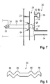
Figur 7 einen vergrößerte Ansicht eines Teils einer vierten Ausführungsform eines erfindungsgemäßen Gargerätes, -
Figur 8 eine Membran eines Gargerätes nachFigur 7 im Schnitt, -
Figur 9 einen vergrößerte Draufsicht eines Teils einer fünften Ausführungsform eines erfindungsgemäßen Gargerätes, und -
Figur 10 einen vergrößerte Draufsicht eines Teils einer sechsten Ausführungsform eines erfindungsgemäßen Gargerätes. - In
Figur 1 ist ein Gargerät 10 gezeigt, das für den Profieinsatz in Großküchen und der Großgastronomie vorgesehen. Es handelt sich hier beispielsweise um einen Kombidämpfer, der unterschiedliche Speisen mit Heißluft und/oder Heißdampf zubereiten kann. Hierzu wird im Garraum 12 eine Atmosphäre erzeugt, die die zum Garen gewünschte Temperatur und Feuchtigkeit aufweist. Die Temperatur und die Feuchtigkeit werden von einer Gargerätsteuerung kontrolliert, die eine Heizvorrichtung und einen Verdampfer steuert. Aus Gründen der Übersichtlichkeit wurde auf die Darstellung der Gargerätsteuerung, der Heizvorrichtung und des Verdampfers verzichtet. - Der Garraum 12 und der Technikraum 14 sind durch eine Rückwand 16 des Garraums 12 voneinander getrennt.
- An der Rückwand 16 ist garraumseitig ein Lüfterrad 18 und ein Resonator 20 angeordnet, wobei das Lüfterrad 18 einen Schallerzeuger 22 darstellt.
- Der Resonator 20 ist mittels einer Befestigung 23 an der Rückwand 16 befestigt. Der Bereich des Gargerätes 10 um den Resonator 20 ist in
Figur 2 vergrößert dargestellt. - Der Resonator 20 ist als Rohr ausgebildet und hat beispielsweise eine Länge L von 20 cm und einen Innendurchmesser zwischen 1,5 cm und 2 cm. Beide Enden des Rohres sind geöffnet, sodass der Resonator 20 ein beidseits offener Resonator ist. Denkbar ist jedoch auch, dass nur eine Seite des Resonators 20 offen ist.
- Der Resonator 20 definiert einen Resonanzraum 24 innerhalb des Rohres. Der Resonanzraum 24 liegt somit innerhalb des Garraums 12 und ist zum Garraum 12 hin geöffnet.
- Das Rohr und somit der Resonator 20 sind vertikal im Garraum 12 angeordnet. Dadurch dringt bei der Reinigung des Gargerätes 10 die Waschflotte auch in das Rohr des Resonators 20 ein und reinigt so den Resonator 20.
- Am Resonator 20 ist ein Hohlraum 26 vorgesehen, der durch einen Schlauch oder ein weiteres Rohr gebildet sein kann.
- Der Hohlraum 26 mündet in den Resonanzraum 24 des Resonators 20, wobei die Stelle, an der der Hohlraum 26 in den Resonanzraum 24 übergeht, als Kopplungsstelle 28 bezeichnet wird.
- An der Kopplungsstelle 28 ist eine dünne Membran 30 vorgesehen, die den Hohlraum 26 gegenüber dem Resonanzraum 24 verschließt, sodass weder heiße Luft, noch Wasserdampf noch Schmutz in den Hohlraum 26 eindringen können.
- Gleichzeitig kann die Membran 30 jedoch schwingen, sodass Schwingungen aus dem Resonanzraum 24 in den Hohlraum 26 übertragen werden können. Der Hohlraum 26 und der Resonanzraum 24 sind also akustisch gekoppelt.
- Die Membran 30 ist beispielsweise zwischen 10 µm und 50 µm dick.
- In der gezeigten Ausführungsform mündet der Hohlraum 26, in Längsrichtung des Resonators 20 betrachtet, mittig in den Resonanzraum 24. In anderen Worten befindet sich die Kopplungsstelle 28 in der gezeigten Ausführungsform auf halber Länge L/2 des Resonators 20.
- Der Durchmesser des Hohlraumes 26 an der Kopplungsstelle 28 unterscheidet sich vom Durchmesser des Resonanzraumes 24. Beispielsweise ist der Durchmesser des Hohlraumes 26 deutlich geringer.
- Der Hohlraum 26 erstreckt sich in die andere Richtung, d. h. vom Resonator 20 ausgehend durch die Rückwand 16 in den Technikraum 14 hinein.
- An dem dem Resonator 20 abgewandten Ende des Hohlraumes 26 läuft der den Hohlraum 26 begrenzende Schlauch oder das Rohr spitz zu und ist verschlossen. Auf diese Weise ist der Hohlraum 26 an seinem der Kopplungsstelle 28 abgewandten Ende schwingungsdämpfend und schwingungsabsorbierend geformt.
- Auch kann im Hohlraum 26 schallabsorbierendes Material 32 vorgesehen sein.
- In der gezeigten Ausführungsform ist in dem Bereich des Hohlraumes 26, der sich innerhalb des Technikraums 14 befindet, ein Mikrofon 34 vorgesehen.
- Außerdem ist in der gezeigten Ausführungsform eine Temperaturwerteinheit 36 in Form eines Temperatursensors am Resonator 20 vorgesehen.
- Im Technikraum 14 ist eine Steuereinheit 38 angeordnet, die mit dem Mikrofon 34 und der Temperaturwerteinheit 36, also dem Temperatursensor verbunden ist. Die Steuereinheit 38 empfängt Signale sowohl vom Mikrofon 34 als auch von der Temperaturwerteinheit 36.
- Die Steuereinheit 38 weist ein Modul 40 auf, das die Signale des Mikrofons 34 erhält und eine Spektralanalyse des empfangenen Signals mittels einer Fourieranalyse- und/oder eine Korrelationsfunktion durchführen kann. Auf diese Weise kann das Modul 40 das Frequenzspektrum (
Fig. 3 ) des Signals des Mikrofons 34 und damit das Frequenzspektrum der Schwingungen im Resonanzraum 24 bestimmen. - Durch einen oder mehrere Durchbrüche 42 in der Wandung des Resonators 20 bzw. des Rohres des Resonators 20 kann Einfluss darauf genommen werden, welche Obertöne sich im Resonator 20 ausbilden können.
- Zur Bestimmung der Feuchtigkeit während des Betriebs des Gargerätes 10 wird zunächst Schall im Garraum 12 erzeugt (S1). Dies geschieht in der gezeigten Ausführungsform durch das Lüfterrad 18, das während seines Betriebs ein breitbandiges Rauschen erzeugt, also als Schallerzeuger 22 mit einem breitbandigen Spektrum dient.
- Der vom Schallerzeuger 22 erzeugte Schall propagiert zum Resonator 20 und regt innerhalb des Resonators 20, d. h. im Resonanzraum 24, die Eigenschwingungen des Resonanzraumes 24 an. Hierdurch bilden sich im Resonanzraum 24 stehende akustische Wellen aus. Dabei können im Resonanzraum 24 neben der Grundschwingung bzw. dem Grundton des Resonators 20 auch ein oder mehrere Obertöne angeregt werden (S2).
- Denkbar ist auch, dass ausschließlich Obertöne angeregt werden, wenn die Frequenz der Grundschwingung außerhalb des Bereiches liegt, der vom Schallerzeuger 22 erzeugt wird.
- Die Grundschwingung des Resonators 20 hat an den beiden Öffnungen des Rohres des Resonators 20 Druckknoten und auf der halben Länge L/2 einen Druckbauch. Dieser Druckbauch bildet sich somit an der Kopplungsstelle 28 aus und führt dazu, dass sich die Schwingungen durch die Membran 30 in den Hohlraum 26 fortpflanzen.
- Im Hohlraum 26 werden die akustischen Schwingungen dann vom Mikrofon 34 aufgenommen und als elektrisches Signal an die Steuereinheit 38, genauer gesagt an das Modul 40 zur Spektralanalyse übermittelt (S3).
- Um zu verhindern, dass sich innerhalb des Hohlraumes 26 ebenfalls eine stehende Welle ausbildet, ist der Hohlraum 26 mit dem schallabsorbierenden Material 32 versehen und verjüngt sich an seinem der Kopplungsstelle 28 abgewandten Ende.
- Außerdem ist der Durchmesser des Hohlraumes 26 geringer gewählt als der des Resonanzraumes 24 bzw. des Resonators 20, sodass die Kopplung zwischen dem System aus Hohlraum 26 und Resonanzraum 24 und dem Resonanzraum 24 alleine verringert wird. Bei zu hoher Kopplung und besonders bei einem zu großen Hohlraum 26 würde der Eigenschwingung im Resonanzraum 24 zu viel Leistung entzogen, wodurch diese Eigenschwingung bedämpft wäre.
- Außerdem kann durch eine geeignete Wahl der Länge des Hohlraumes 26 die Resonanzfrequenz des Systems aus Hohlraum 26 und Resonanzraum 24 genügend weit von der Resonanzfrequenz des Resonanzraumes 24 alleine entfernt gewählt werden.
- Das Modul 40 zur Spektralanalyse empfängt die vom Mikrofon 34 aufgenommenen Signale und ermittelt mithilfe einer Fourieranalyse- und/oder Korrelationsfunktionen das Frequenzspektrum des Signals und damit das Frequenzspektrum der im Resonanzraum 24 angeregten Schwingungen (S4).
- Ein solches ermitteltes Spektrum ist in
Figur 3 dargestellt. Anhand des ermittelten Frequenzspektrums bestimmt das Modul 40 die Frequenz F0 der Grundschwingung bzw. des Grundtones der Eigenschwingungen des Resonanzraumes 24 (S5). - Im in
Figur 3 gezeigten Fall ist die Frequenz F0 der Grundschwingung einfach aus dem Frequenzspektrum ablesbar. Gegebenenfalls kann der abgelesene Wert F0 mit den Frequenzen F1, F2, F3 verglichen und korrigiert werden. - Im Falle, dass die Grundschwingung nicht im Resonanzraum 24 angeregt wurde und deswegen im Frequenzspektrum nicht vorhanden ist, bestimmt das Modul 40 anhand der Abstände der Frequenzen F1, F2, F3 der im Frequenzspektrum auftretenden Obertöne die Frequenz Foder Grundschwingung.
- Dadurch, dass ständig oder in regelmäßigen Abständen das gesamte Spektrum der im Resonanzraum 24 erzeugten Schwingungen bestimmt wird, ist es unerheblich, wie genau der Schallerzeuger 22 betrieben oder angesteuert wird. Der Schallerzeuger 22 muss lediglich ein breitbandiges Signal erzeugen, das akustische Schwingungen im Resonanzraum 24 anregt. Eine Abstimmung der Phase des erzeugten Schalls o. Ä. ist nicht nötig. Die Bestimmung der Feuchtigkeit und des Frequenzspektrums erfolgt somit unabhängig von der Ansteuerung der Schallquelle.
- Auf Basis der von dem Modul 40 zur Spektralanalyse bestimmten Frequenz F0 bestimmt die Steuereinheit 38 nun die Schallgeschwindigkeit innerhalb des Resonanzraumes 24 mithilfe der Formel c = λ0 · F0, wobei λ0 die Wellenlänge der Grundschwingung ist. Die Wellenlänge der Grundschwingung λ0 ist aufgrund der Geometrie des Resonanzraumes 24 bekannt und in der Steuereinheit 38 hinterlegt. In der gezeigten Ausführungsform entspricht die Wellenlänge λ0 etwa der doppelten Länge 2L des Resonators 20 (S6).
- Um die Feuchtigkeit innerhalb des Garraums bestimmen zu können, benötigt die Steuereinheit 38 den Wert der Temperatur T im Resonanzraum 24.
- Hierzu wird zunächst in einem Schritt S7 von der Temperaturwerteinheit 36 ein Temperaturwert erzeugt.
- In der gezeigten Ausführungsform ist die Temperaturwerteinheit 36 der Temperatursensor am Resonator 20, sodass durch Messung der Temperatur des Resonators 20 der Temperaturwert erzeugt wird.
- Denkbar ist jedoch auch, dass die Temperaturwerteinheit 36 den Temperaturwert aus Daten der Gargerätsteuerung erzeugt. Beispielsweise entnimmt die Temperaturwerteinheit 36 die Solltemperatur der Heizvorrichtung aus der Gargerätsteuerung.
- Die Steuereinheit 38 empfängt im Schritt S8 den Temperaturwert und passt den Temperaturwert gegebenenfalls an. Dies kann nötig sein, wenn sich der Resonator 20 außerhalb des Garraums 12 befindet, aber mit diesem in Verbindung steht, sodass er mit der Garraumatmosphäre gefüllt ist, während der Temperatursensor jedoch innerhalb des Garraums 12 vorgesehen ist, sodass die Temperatur T im Resonanzraum 24 geringer ist als die gemessene Temperatur im Garraum 12. In diesem Falle kann die Steuereinheit 38 den von der Temperaturwerteinheit 36 empfangenen Wert korrigieren. Auch korrigiert die Steuereinheit 38 den Temperaturwert gegebenenfalls dann, wenn der Temperaturwert, wie zuvor beschrieben, auf andere Weise von der Temperaturwerteinheit 36 erzeugt wurde, beispielsweise wenn der Temperaturwert 36 die Solltemperatur der Heizvorrichtung ist.
- In der gezeigten Ausführungsform entspricht der Temperaturwert jedoch direkt der Temperatur des Resonators 20 und damit der Temperatur T des Resonanzraumes 24 und kann sofort verwendet werden.
- Nun bestimmt die Steuereinheit 38 im Schritt S9 die Feuchtigkeit im Garraum 12 mithilfe der ermittelten Schallgeschwindigkeit c und der Temperatur T im Resonanzraum 24. Die Schallgeschwindigkeit c ist abhängig von der Temperatur T und der Zusammensetzung der Atmosphäre innerhalb des Resonanzraumes 24. Für ideale Gase gilt:

- Matmo und Katmo bzw. deren Verhältnis können also bestimmt werden, da die Schallgeschwindigkeit c, die universelle Gaskonstante Rmol und die Temperatur T bekannt sind. Diese Näherung beschreibt auch die realen Gase Wasserdampf und Luft relativ gut. Es können aber, insbesondere für Wasserdampf, Abweichungen vom Verhalten idealer Gase berücksichtigt werden. Alternativ kann ein empirischer Zusammenhang zwischen Schallgeschwindigkeit und Gaszusammensetzung verwendet werden.
- Auf diese Weise lässt sich die Zusammensetzung der Atmosphäre im Resonanzraum 24 bestimmen, d. h. der Anteil von Wasserdampf zu Luft in der Atmosphäre, wodurch auch die Feuchtigkeit in der Atmosphäre im Garraum 12 bestimmt ist.
- Selbstverständlich können die beiden Gleichungen auch ineinander eingesetzt und nach dem Verhältnis von Matmo zu Katmo aufgelöst werden. Denkbar sind auch noch weitere Berechnungsarten dieses Verhältnisses.
- Der auf diese Weise bestimmte Wert der Feuchtigkeit kann nun von der Steuereinheit 38 an die Gargerätsteuerung des Gargerätes 10 übergeben werden.
- Im Folgenden werden weitere Ausführungsformen des erfindungsgemäßen Gargeräts beschrieben, die im Wesentlichen der ersten Ausführungsform entsprechen. Gleiche oder funktionsgleiche Teile werden mit denselben Bezugszeichen versehen und es wird nur auf die Unterschiede eingegangen.
-
Figur 5 zeigt eine vergrößerte Darstellung eines Teils eines erfindungsgemäßen Gargerätes 10 gemäß einer zweiten Ausführungsform der Erfindung. Die Darstellung derFigur 5 entspricht der Darstellung derFigur 2 zur ersten Ausführungsform. - Im Unterschied zur ersten Ausführungsform ist kein Hohlraum 26 vorgesehen, sondern das Mikrofon 34 ist direkt im Resonator 20, also im Resonanzraum 24, angeordnet.
- Das Mikrofon 34 kann dabei an der Stelle angeordnet sein, an der die Kopplungsstelle 28 in der ersten Ausführungsform angeordnet war, d. h. in Längsrichtung des Rohres des Resonators 20 etwa auf der halben Länge L/2.
- Denkbar ist auch, dass das Mikrofon 34 oder die Kopplungsstelle 28 einen Abstand vom Ende des Rohrs hat, der zwischen 10% und 15%, insbesondere etwa 13% der Länge des Rohres beträgt. Dadurch wird eine besonders präzise Messung möglich, da dort die unteren Eigenmoden mehr als ihren halben Maximalpegel haben.
- Durch die Anordnung des Mikrofons 34 im Resonanzraum 24 kann die Temperatur im Resonanzraum 24 direkt gemessen werden. Jedoch ist in dieser Ausführungsform das Mikrofon 34 auch der heißen und zum Teil fettigen Atmosphäre im Garraum ausgesetzt, wodurch die Anforderungen an die Belastbarkeit des Mikrofons 34 deutlich steigen.
- In
Figur 6 ist eine dritte Ausführungsform eines erfindungsgemäßen Gargeräts 10 dargestellt. - In der dritten Ausführungsform nach
Figur 6 ist kein separater Resonator 20 vorgesehen, sondern der Garraum 12 dient selbst als Resonanzraum 24. - Auch die Methode zur Erzeugung von akustischen Schwingungen im Resonanzraum 24 unterscheidet sich von der der ersten Ausführungsform.
- In der Ausführungsform nach
Figur 6 ist der Schallerzeuger 22 ein Lautsprecher 44. - Der Lautsprecher 44 ist in einem Lautsprecherraum 46 vorgesehen, der sich innerhalb des Technikraums 14 befindet und der durch eine Leitung 48 mit dem Garraum 12 in Verbindung steht.
- In der Leitung 48 ist eine weitere Membran 50 vorgesehen, die eine akustische Kopplung zwischen dem Garraum 12 und dem Lautsprecherraum 46 ermöglicht, gleichzeitig jedoch den Lautsprecher 44 vor der Atmosphäre des Garraumes 12 schützt.
- Denkbar ist selbstverständlich auch, dass der Lautsprecher 44 im Garraum 12 angeordnet ist.
- Mit dem Lautsprecher 44 ist eine Lautsprechersteuerung 52 elektrisch verbunden, die den Lautsprecher 44 ansteuert.
- In der gezeigten Ausführungsform ist das Mikrofon 34 in zentraler Position am Boden des Garraums 12 angeordnet. Denkbar ist selbstverständlich auch die Anbringung des Mikrofons 34 an einer Seitenwand oder der Decke des Garraums 12.
- Die Lautsprechersteuerung 52 steuert den Lautsprecher 44 so, dass dieser weißes Rauschen, also ein breitbandiges Schallsignal emittiert.
- Alternativ kann der Lautsprecher 44 durch die Ansteuerung der Lautsprechersteuerung 52 Frequenzsweeps durchführen. Dabei erzeugt der Lautsprecher 44 akustische Schwingungen mit jeweils einer Frequenz, also reine Töne, wobei die Tonhöhe, d. h. die Frequenz dieser Schwingungen ein vorbestimmtes Frequenzband wiederholt durchläuft. Somit ist die Ausgabe des Lautsprechers 44 auch in diesem Falle breitbandig, da Töne mit verschiedenen Frequenzen erzeugt werden.
- Durch den Lautsprecher 44 angeregt, bilden sich nun im Garraum 12, ähnlich wie im Resonator 20 der ersten Ausführungsform, stehende Wellen aus, die der Grundschwingung und/oder Obertönen des Resonanzraumes 24 entsprechen.
- Die Schwingungen werden auch in dieser Ausführungsform vom Mikrofon 34 erfasst und die Bestimmung der Frequenz F0 der Grundschwingung des Garraums 12 und die Bestimmung der Feuchtigkeit innerhalb des Garraums 12 erfolgt auf die gleiche Weise, die zur ersten Ausführungsform beschrieben wurde.
- In
Figur 7 ist eine vierte Ausführungsform eines erfindungsgemäßen Gargeräts dargestellt. Die Ansicht derFigur 7 ähnelt dabei stark derjenigen derFigur 2 . - Der Resonator 20 der vierten Ausführungsform weist ein erstes Rohr 54, das dem Rohr der ersten Ausführungsform entspricht, ein zweites Rohr 56 und eine Kavität 58 auf.
- Das erste Rohr 54 hat ein Innenvolumen, das einen Teil des Resonanzraumes 24 bildet.
- Das zweite Rohr 56 geht vom ersten Rohr 54 aus und ist an seinem vom ersten Rohr 54 abgewandten Ende offen, d.h. es mündet in den Garraum 12.
- Das Innenvolumen des zweiten Rohres 56 ist somit direkt mit dem Innenvolumen des ersten Rohres 54 verbunden und bildet ebenfalls einen Teil des Resonanzraumes 24.
- Die Kavität 58 ist ein Gefäß mit einem abgeschlossenen Innenvolumen, das nur mit dem Innenvolumen des ersten Rohres 54 direkt verbunden ist. Das Innenvolumen der Kavität 58 ist somit ebenfalls Teil des Resonanzraumes 24.
- In der gezeigten Ausführungsform besteht die Kavität 58 aus einem quaderförmigen Hohlkörper 60, der über eine Verbindungsleitung 62 mit dem ersten Rohr 54 verbunden ist. Eine solche Konstruktion wird auch Helmholtz-Resonator genannt.
- Dadurch, dass der Resonanzraum 24 nun neben dem Innenvolumen des ersten Rohres 54 weitere Volumina aufweist, ändert sich das Spektrum an Resonanzfrequenzen, die sich im Resonanzraum 24 und damit im Resonator 20 ausbilden können. Dadurch ergibt sich für den Resonator 20 ein charakteristisches Frequenzspektrum (auch Resonanzspektrum genannt) der im Resonator 20 vorhandenen Schwingungen, das zur Bestimmung der Schallgeschwindigkeit und damit der Luftfeuchtigkeit herangezogen werden kann. Da das charakteristische Frequenzspektrum aus mehreren Frequenzen besteht ist es einfacher von den Frequenzen von Störquellen zu unterscheiden.
- Die einzelnen Frequenzen des Frequenzspektrums können durch die Dimensionen des zweiten Rohres 56 und der Kavität 58 und deren Ankopplungspunkte an das erste Rohr 54 beeinflusst werden.
- Die in der
Figur 7 gezeigten Stellen sind somit nur Beispiele. - Außerdem ist die Temperaturwerteinheit 36 in dieser vierten Ausführungsform innerhalb des Resonators 20 vorgesehen.
- Die Temperaturwerteinheit 36 kann sich im Bereich der Kopplungsstelle 28 befinden, z. B. gegenüber der Mündung des Hohlraumes 26.
- Zudem ist in der vierten Ausführungsform an der Kopplungsstelle 28 eine Stufe 64 vorgesehen. Die Stufe 64 ist plan und dient als Auflagefläche für die Membran 30.
- Die Membran 30 ist in dieser Ausführungsform, wie in
Figur 8 zu sehen, geprägt, sodass sie im Querschnitt wellenförmig ist und sich zwei zueinander und zur Membran 30 konzentrische Ringe 66 bilden. - Durch diese Ringe 66 werden Spannungen in der Membran 30, die sich beim Einbau der Membran 30 in das Gargerät 10 ergeben, aufgenommen. Dadurch kann der Bereich innerhalb des innersten Ringes 66 von Spannungen frei gehalten werden, wodurch seine Schwingungseigenschaften, wie seine Rückstellkraft, durch den Einbau nicht beeinträchtigt sind.
- In
Figur 9 ist eine fünfte Ausführungsform der Erfindung zu sehen. DieFigur 9 zeigt einen horizontalen Schnitt durch die Garraumwand, den Hohlraum 26 und den Resonator 20. - Der Resonator 20 weist auch in dieser Ausführungsform ein erstes Rohr 54 und ein zweites Rohr 56 auf, wobei die beiden Rohre 54 und 56 nun parallel verlaufen. Außerdem haben die beiden Innenvolumina der Rohre 54 und 56 keinen direkten fluidischen Kontakt. Trotzdem bilden die beiden Rohre 54 und 56 aufgrund ihrer Nähe zueinander den Resonator 20.
- Die Rohre 54, 56 haben unterschiedliche Durchmesser und Längen. Beispielsweise ist das erste Rohr 54 kürzer und hat einen kleineren Durchmesser als das zweite Rohr 56.
- Der Hohlraum 26 ist in dieser Ausführungsform mit beiden Rohren 54, 56 genauer gesagt mit beiden Innenvolumina der Rohre 54, 56 verbunden. Hierzu ist jeweils eine Kopplungsstelle 28 und eine Membran 30 vorgesehen.
- Auch ist es denkbar, dass in jeder der Rohre 54, 56 eine eigene Temperaturwerteinheit 36 vorgesehen ist.
- Der Effekt der beiden Rohre 54, 56 des Resonators 20 ist der gleiche wir zur vierten Ausführungsform beschrieben, da das zweite Rohr 56 dem Frequenzspektrum des Resonators 20 weitere Frequenzen hinzufügt.
- In
Figur 10 ist eine sechste Ausführungsform der Erfindung gezeigt. Diese entspricht im Wesentlichen der fünften Ausführungsform, jedoch sind in dieser sechsten Ausführungsform zwei Hohlräume 26 vorgesehen, die mit jeweils einem der Rohre 54, 56 verbunden sind, so wie zur ersten Ausführungsform beschrieben. - Die Mikrofone 34 der beiden Hohlräume 26 sind mit der Steuereinheit 38 verbunden.
- Es kann vorgesehen sein, dass die Ausführungsform nach
Figur 1 auch ohne einen separaten Resonator 20 ausgeführt sein kann und/oder ebenfalls der Garraum 12 als Resonanzraum 24 verwendet wird. - Auch kann in der ersten Ausführungsform ein Lautsprecher 44 als Schallerzeuger 22 dienen.
- Denkbar ist es auch, dass die Steuereinheit 38 und/oder die Lautsprechersteuerung 52 in der Gargerätsteuerung integriert sind.
Claims (21)
- Verfahren zur Bestimmung der Feuchtigkeit innerhalb eines Garraumes (12) eines Gargerätes (10), mit den folgenden Schritten:a) in einem Resonanzraum (24) im Gargerät (10) wird mittels eines Schallerzeugers (22) ein akustisches breitbandiges Signal erzeugt,b) eine Steuereinheit (38) empfängt von einem Mikrofon (34) im Resonanzraum (24) aufgenommene Signale,c) die Steuereinheit (38) bestimmt anhand der empfangenen Signale das Frequenzspektrum des im Resonanzraum (24) vorhandenen akustischen Signals unabhängig von der Ansteuerung des Schallerzeugers (22) und anhand der Grundfrequenz des Frequenzspektrums oder Obertönen des Frequenzspektrums, aus denen die Grundfrequenz bestimmbar ist, die Schallgeschwindigkeit innerhalb des Resonanzraums (24), wobei der Resonanzraum (24) mit Garraumatmosphäre gefüllt ist,d) die Steuereinheit (38) empfängt oder bestimmt einen Temperaturwert, wobei der Temperaturwert einer Temperatur im Resonanzraum (24) entspricht,e) die Steuereinheit (38) bestimmt mithilfe des Temperaturwertes und der Schallgeschwindigkeit die Feuchtigkeit innerhalb des Garraums (12).
- Verfahren nach Anspruch 1, dadurch gekennzeichnet, dass die Steuereinheit (38) das Frequenzspektrum mittels einer Fourieranalyse und/oder durch die Bestimmung einer Korrelationsfunktion ermittelt.
- Gargerät mit einem Garraum (12), einem Resonanzraum (24), einem Schallerzeuger (22), der dazu ausgebildet ist, ein breitbandiges Signal im Resonanzraum (24) zu erzeugen, einem dem Resonanzraum (24) zugeordneten Mikrofon (34), einer Temperaturwerteinheit (36), die ein von der Temperatur der Atmosphäre im Resonanzraum (24) abhängiges Signal erzeugen kann, und einer Steuereinheit (38), an die das Mikrofon (34) und die Temperaturwerteinheit (36) angeschlossen sind, wobei die Steuereinheit (38) ein Modul (40) zur Spektralanalyse enthält, insbesondere ein Fourieranalyse- und/oder ein Korrelationsfunktions-Modul, und wobei die Steuereinheit (38) dazu ausgebildet und eingerichtet ist, anhand der vom Mikrofon (34) empfangenen Signale ein Frequenzspektrum des im Resonanzraum (24) vorhandenen akustischen Signals unabhängig von der Ansteuerung des Schallerzeugers (22) zu bestimmen und anhand der Grundfrequenz des Frequenzspektrums oder Obertönen des Frequenzspektrums, aus denen die Grundfrequenz bestimmbar ist, die Schallgeschwindigkeit innerhalb des Resonanzraums (24) und mithilfe des Temperaturwertes und der Schallgeschwindigkeit die Feuchtigkeit innerhalb des Garraums (12) gemäß dem einem Verfahren nach einem der Ansprüche 1 oder 2 zu bestimmen.
- Gargerät nach Anspruch 3, dadurch gekennzeichnet, dass das Gargerät (10) ein Lüfterrad (18) aufweist, wobei das Lüfterrad (18) den Schallerzeuger (22) darstellt.
- Gargerät nach Anspruch 3, dadurch gekennzeichnet, dass das Gargerät (10) einen Lautsprecher (44) aufweist, wobei der Lautsprecher (44) den Schallerzeuger (22) darstellt.
- Gargerät nach Anspruch 5, dadurch gekennzeichnet, dass das Gargerät (10) eine Lautsprechersteuerung (52) aufweist, die derart ausgebildet ist, dass sie den Lautsprecher (44) derart steuert, dass der Lautsprecher (44) ein Rauschen emittiert oder einen Frequenzsweep durchführt.
- Gargerät nach einem der Ansprüche 3 bis 6, dadurch gekennzeichnet, dass der Garraum (12) des Gargerätes (10) der Resonanzraum (24) ist.
- Gargerät nach einem der Ansprüche 3 bis 6, dadurch gekennzeichnet, dass der Resonanzraum (24) innerhalb eines Resonators (20) liegt, der zum Garraum (12) des Gargeräts (10) offen ist.
- Gargerät nach Anspruch 8, dadurch gekennzeichnet, dass der Resonator (20) im Garraum (12) des Gargerätes (10) angeordnet ist.
- Gargerät nach Anspruch 8 oder 9, dadurch gekennzeichnet, dass der Resonator (20) als Rohr ausgeführt ist.
- Gargerät nach Anspruch 8 oder 9, dadurch gekennzeichnet, dass der Resonator (20) ein erstes Rohr (54) und ein mit dem ersten Rohr (54) akustisch gekoppeltes zweites Rohr (56) und/oder eine mit dem ersten Rohr (54) akustisch gekoppelte Kavität (58) aufweist.
- Gargerät nach Anspruch 11, dadurch gekennzeichnet, dass das zweite Rohr (56) und/oder die Kavität (58) vom ersten Rohr (54) ausgehen.
- Gargerät nach einem der Ansprüche 3 bis 12, dadurch gekennzeichnet, dass das Gargerät (10) einen Hohlraum (26) aufweist, der mit dem Resonanzraum (24) an einer Kopplungsstelle (28) akustisch gekoppelt ist, wobei das Mikrofon (34) im Hohlraum (26) vorgesehen ist.
- Gargerät nach Anspruch 13, dadurch gekennzeichnet, dass der Hohlraum (26) eine Membran (30) aufweist, die in der Kopplungsstelle (28) angeordnet ist.
- Gargerät nach Anspruch 14, dadurch gekennzeichnet, dass die Membran (30) eine Prägung aus wenigstens einem konzentrischen Ring (66) aufweist.
- Gargerät nach einem der Ansprüche 13 bis 15, dadurch gekennzeichnet, dass der Hohlraum (26) an seinem der Kopplungsstelle (28) abgewandten Ende schwingungsdämpfend oder schwingungsabsorbierend geformt ist, insbesondere sich von der Kopplungsstelle (28) ausgehend verjüngt, insbesondere spitz zuläuft.
- Gargerät nach einem der Ansprüche 13 bis 16, dadurch gekennzeichnet, dass der Hohlraum (26), insbesondere an seinem der Kopplungsstelle (28) abgewandten Ende, mit schallabsorbierendem Material (32) versehen ist.
- Gargerät nach einem der Ansprüche 13 bis 17, dadurch gekennzeichnet, dass sich der Hohlraum (26) zur Kopplungsstelle (28) hin trichterförmig aufweitet.
- Gargerät nach einem der Ansprüche 3 bis 10, dadurch gekennzeichnet, dass das Mikrofon (34) im Resonanzraum (24) vorgesehen ist.
- Gargerät nach einem der Ansprüche 3 bis 19, dadurch gekennzeichnet, dass das Mikrofon (34) oder die Kopplungsstelle (28) im Bereich des Maximums des Schalldruckes einer oder mehrerer Eigenschwingungen des Resonanzraumes (24) angeordnet ist.
- Gargerät nach einem der Ansprüche 3 bis 20, dadurch gekennzeichnet, dass die Temperaturwerteinheit (36) am oder im Resonator (20), insbesondere im Bereich der Kopplungsstelle (28) vorgesehen ist.
Applications Claiming Priority (2)
| Application Number | Priority Date | Filing Date | Title |
|---|---|---|---|
| DE102016112683.7A DE102016112683B4 (de) | 2016-07-11 | 2016-07-11 | Verfahren zur Bestimmung der Feuchtigkeit innerhalb eines Garraumes eines Gargeräts sowie Gargerät |
| PCT/EP2017/067408 WO2018011210A1 (de) | 2016-07-11 | 2017-07-11 | Verfahren zur bestimmung der feuchtigkeit innerhalb eines garraumes eines gargeräts sowie gargerät |
Publications (2)
| Publication Number | Publication Date |
|---|---|
| EP3481204A1 EP3481204A1 (de) | 2019-05-15 |
| EP3481204B1 true EP3481204B1 (de) | 2022-08-31 |
Family
ID=59313263
Family Applications (1)
| Application Number | Title | Priority Date | Filing Date |
|---|---|---|---|
| EP17737587.0A Active EP3481204B1 (de) | 2016-07-11 | 2017-07-11 | Verfahren zur bestimmung der feuchtigkeit innerhalb eines garraumes eines gargeräts sowie gargerät |
Country Status (4)
| Country | Link |
|---|---|
| US (1) | US11193911B2 (de) |
| EP (1) | EP3481204B1 (de) |
| DE (1) | DE102016112683B4 (de) |
| WO (1) | WO2018011210A1 (de) |
Families Citing this family (3)
| Publication number | Priority date | Publication date | Assignee | Title |
|---|---|---|---|---|
| US12616173B2 (en) * | 2015-06-16 | 2026-05-05 | Radio Systems Corporation | Apparatus and method for delivering an auditory stimulus |
| JP7557345B2 (ja) * | 2020-11-09 | 2024-09-27 | シャープ株式会社 | 加熱調理器 |
| US20230375182A1 (en) * | 2022-05-20 | 2023-11-23 | Whirlpool Corporation | System and method for moisture and ambient humidity level prediction for food doneness |
Family Cites Families (7)
| Publication number | Priority date | Publication date | Assignee | Title |
|---|---|---|---|---|
| DE906023C (de) * | 1948-10-02 | 1954-04-05 | Norbert Kurt Endell Dipl Ing | Einrichtung zur Messung des Feuchtigkeitsgehalts von Gasen |
| GB931233A (en) * | 1960-10-28 | 1963-07-17 | Gen Dynamics Corp | Improved temperature measuring apparatus |
| US4208906A (en) * | 1978-05-08 | 1980-06-24 | Interstate Electronics Corp. | Mud gas ratio and mud flow velocity sensor |
| US5689060A (en) * | 1992-03-06 | 1997-11-18 | Matsushita Electric Industrial Co., Ltd. | Humidity measuring device and a heat cooker employing the device |
| ATE365456T1 (de) * | 2001-10-06 | 2007-07-15 | Neubauer Kurt Mkn Maschf | Gargerät mit feuchtemesseinrichtung und verfahren zur feuchtemessung in einem gargerät |
| SE0201073D0 (sv) * | 2002-04-09 | 2002-04-09 | Siemens Elema Ab | Acoustic Gas Monitor |
| EP2221613A1 (de) * | 2009-02-19 | 2010-08-25 | Electrolux Home Products Corporation N.V. | Vorrichtung und Verfahren zur Einschätzung der Luftfeuchtigkeit in einem Ofenhohlraum |
-
2016
- 2016-07-11 DE DE102016112683.7A patent/DE102016112683B4/de active Active
-
2017
- 2017-07-11 EP EP17737587.0A patent/EP3481204B1/de active Active
- 2017-07-11 WO PCT/EP2017/067408 patent/WO2018011210A1/de not_active Ceased
- 2017-07-11 US US16/316,960 patent/US11193911B2/en active Active
Also Published As
| Publication number | Publication date |
|---|---|
| DE102016112683B4 (de) | 2025-08-21 |
| DE102016112683A1 (de) | 2018-01-11 |
| EP3481204A1 (de) | 2019-05-15 |
| US11193911B2 (en) | 2021-12-07 |
| WO2018011210A1 (de) | 2018-01-18 |
| US20210041396A1 (en) | 2021-02-11 |
Similar Documents
| Publication | Publication Date | Title |
|---|---|---|
| DE19861018C2 (de) | Gesteuerter akustischer Wellenleiter zur Schalldämpfung | |
| WO2004001344A1 (de) | Verfahren zum bestimmen rheologischer parameter eines fluids | |
| WO2018011210A1 (de) | Verfahren zur bestimmung der feuchtigkeit innerhalb eines garraumes eines gargeräts sowie gargerät | |
| EP3486630B1 (de) | Messeinrichtung zur ermittlung eines drucks in einem messvolumen | |
| DE4217624A1 (de) | Kalibrierung von seismischen kabeln in einem helmholz-resonator | |
| EP0481450A1 (de) | Schalldämpferanlage für Verbrennungsmotoren | |
| EP3521774B1 (de) | Ultraschall-durchflussmessvorrichtung und verfahren zum bestimmen der strömungsgeschwindigkeit | |
| WO2016150621A1 (de) | VORRICHTUNG ZUR BESTIMMUNG UND/ODER ÜBERWACHUNG ZUMINDEST EINER PROZESSGRÖßE | |
| DE102018123797B4 (de) | Verfahren zur Erzeugung eines Erregersignals sowie zur akustischen Messung in technischen Hohlräumen | |
| AT515552A4 (de) | Verfahren und Vorrichtung zur Ermittlung eines Dichtewertes | |
| DE102005025671B3 (de) | Verfahren und Vorrichtung zur Messung der spezifischen Dichte eines gasförmigen oder flüssigen Mediums | |
| EP1300079B1 (de) | Gargerät mit Feuchtemesseinrichtung und Verfahren zur Feuchtemessung in einem Gargerät | |
| EP3894799B1 (de) | Ultraschallwandleranordnung einer clamp-on-ultraschall-durchflussmessstelle, und eine clamp-on-ultraschall-durchflussmessstelle sowie verfahren zur inbetriebnahme der clamp-on-ultraschall-durchflussmessstelle | |
| DE10143841B4 (de) | Gargerät mit Feuchtemesseinrichtung | |
| EP1419380A1 (de) | Verfahren und vorrichtung zur ermittlung akustischer parameter von flüssigkeiten in einer resonatoranordnung | |
| DE102016112680B4 (de) | Gargerät | |
| DE102016112679B4 (de) | Verfahren und Anordnung zur Analyse von Gaseigenschaften | |
| DE102020129196A1 (de) | Ultraschallwandler, Verfahren zum Betreiben eines Ultraschallwandlers, Ultraschalldurchflussmessgerät und Verfahren zum Betreiben eines Ultraschalldurchflussmessgeräts | |
| DE102016112678A1 (de) | Verfahren und Anordnung zur Analyse von Gaseigenschaften | |
| DE102005035085B4 (de) | Verfahren zur Einstellung der akustischen Eigenschaften einer Brennkammer | |
| DE102010006576A1 (de) | Gaskonzentrationssensor, Kraftfahrzeug mit Gaskonzentrationssensor sowie Gaskonzentrationsmessverfahren | |
| DE102024132291B3 (de) | Verfahren zum Betreiben eines Ultraschalldurchflussmessgeräts und Ultraschalldurchflussmessgerät | |
| DE102024132307B3 (de) | Verfahren zum Betreiben eines Ultraschalldurchflussmessgeräts und entsprechendes Ultraschalldurchflussmessgerät | |
| DE69616999T2 (de) | Vorrichtung zur strömungsgeschwindigkeitsmessung einer flüssigkeit mittels ultraschall | |
| DE102020001783A1 (de) | Kochfeldunterstützungssystem |
Legal Events
| Date | Code | Title | Description |
|---|---|---|---|
| STAA | Information on the status of an ep patent application or granted ep patent |
Free format text: STATUS: UNKNOWN |
|
| STAA | Information on the status of an ep patent application or granted ep patent |
Free format text: STATUS: THE INTERNATIONAL PUBLICATION HAS BEEN MADE |
|
| PUAI | Public reference made under article 153(3) epc to a published international application that has entered the european phase |
Free format text: ORIGINAL CODE: 0009012 |
|
| STAA | Information on the status of an ep patent application or granted ep patent |
Free format text: STATUS: REQUEST FOR EXAMINATION WAS MADE |
|
| 17P | Request for examination filed |
Effective date: 20190107 |
|
| AK | Designated contracting states |
Kind code of ref document: A1 Designated state(s): AL AT BE BG CH CY CZ DE DK EE ES FI FR GB GR HR HU IE IS IT LI LT LU LV MC MK MT NL NO PL PT RO RS SE SI SK SM TR |
|
| AX | Request for extension of the european patent |
Extension state: BA ME |
|
| DAV | Request for validation of the european patent (deleted) | ||
| DAX | Request for extension of the european patent (deleted) | ||
| STAA | Information on the status of an ep patent application or granted ep patent |
Free format text: STATUS: EXAMINATION IS IN PROGRESS |
|
| 17Q | First examination report despatched |
Effective date: 20210202 |
|
| GRAP | Despatch of communication of intention to grant a patent |
Free format text: ORIGINAL CODE: EPIDOSNIGR1 |
|
| STAA | Information on the status of an ep patent application or granted ep patent |
Free format text: STATUS: GRANT OF PATENT IS INTENDED |
|
| INTG | Intention to grant announced |
Effective date: 20220114 |
|
| GRAJ | Information related to disapproval of communication of intention to grant by the applicant or resumption of examination proceedings by the epo deleted |
Free format text: ORIGINAL CODE: EPIDOSDIGR1 |
|
| STAA | Information on the status of an ep patent application or granted ep patent |
Free format text: STATUS: EXAMINATION IS IN PROGRESS |
|
| GRAS | Grant fee paid |
Free format text: ORIGINAL CODE: EPIDOSNIGR3 |
|
| STAA | Information on the status of an ep patent application or granted ep patent |
Free format text: STATUS: GRANT OF PATENT IS INTENDED |
|
| INTC | Intention to grant announced (deleted) | ||
| GRAP | Despatch of communication of intention to grant a patent |
Free format text: ORIGINAL CODE: EPIDOSNIGR1 |
|
| INTG | Intention to grant announced |
Effective date: 20220620 |
|
| GRAA | (expected) grant |
Free format text: ORIGINAL CODE: 0009210 |
|
| STAA | Information on the status of an ep patent application or granted ep patent |
Free format text: STATUS: THE PATENT HAS BEEN GRANTED |
|
| AK | Designated contracting states |
Kind code of ref document: B1 Designated state(s): AL AT BE BG CH CY CZ DE DK EE ES FI FR GB GR HR HU IE IS IT LI LT LU LV MC MK MT NL NO PL PT RO RS SE SI SK SM TR |
|
| REG | Reference to a national code |
Ref country code: CH Ref legal event code: EP Ref country code: GB Ref legal event code: FG4D Free format text: NOT ENGLISH |
|
| REG | Reference to a national code |
Ref country code: AT Ref legal event code: REF Ref document number: 1514629 Country of ref document: AT Kind code of ref document: T Effective date: 20220915 Ref country code: DE Ref legal event code: R096 Ref document number: 502017013724 Country of ref document: DE |
|
| REG | Reference to a national code |
Ref country code: IE Ref legal event code: FG4D Free format text: LANGUAGE OF EP DOCUMENT: GERMAN |
|
| REG | Reference to a national code |
Ref country code: LT Ref legal event code: MG9D |
|
| REG | Reference to a national code |
Ref country code: NL Ref legal event code: MP Effective date: 20220831 |
|
| PG25 | Lapsed in a contracting state [announced via postgrant information from national office to epo] |
Ref country code: SE Free format text: LAPSE BECAUSE OF FAILURE TO SUBMIT A TRANSLATION OF THE DESCRIPTION OR TO PAY THE FEE WITHIN THE PRESCRIBED TIME-LIMIT Effective date: 20220831 Ref country code: RS Free format text: LAPSE BECAUSE OF FAILURE TO SUBMIT A TRANSLATION OF THE DESCRIPTION OR TO PAY THE FEE WITHIN THE PRESCRIBED TIME-LIMIT Effective date: 20220831 Ref country code: NO Free format text: LAPSE BECAUSE OF FAILURE TO SUBMIT A TRANSLATION OF THE DESCRIPTION OR TO PAY THE FEE WITHIN THE PRESCRIBED TIME-LIMIT Effective date: 20221130 Ref country code: LV Free format text: LAPSE BECAUSE OF FAILURE TO SUBMIT A TRANSLATION OF THE DESCRIPTION OR TO PAY THE FEE WITHIN THE PRESCRIBED TIME-LIMIT Effective date: 20220831 Ref country code: LT Free format text: LAPSE BECAUSE OF FAILURE TO SUBMIT A TRANSLATION OF THE DESCRIPTION OR TO PAY THE FEE WITHIN THE PRESCRIBED TIME-LIMIT Effective date: 20220831 Ref country code: FI Free format text: LAPSE BECAUSE OF FAILURE TO SUBMIT A TRANSLATION OF THE DESCRIPTION OR TO PAY THE FEE WITHIN THE PRESCRIBED TIME-LIMIT Effective date: 20220831 |
|
| PG25 | Lapsed in a contracting state [announced via postgrant information from national office to epo] |
Ref country code: PL Free format text: LAPSE BECAUSE OF FAILURE TO SUBMIT A TRANSLATION OF THE DESCRIPTION OR TO PAY THE FEE WITHIN THE PRESCRIBED TIME-LIMIT Effective date: 20220831 Ref country code: IS Free format text: LAPSE BECAUSE OF FAILURE TO SUBMIT A TRANSLATION OF THE DESCRIPTION OR TO PAY THE FEE WITHIN THE PRESCRIBED TIME-LIMIT Effective date: 20221231 Ref country code: HR Free format text: LAPSE BECAUSE OF FAILURE TO SUBMIT A TRANSLATION OF THE DESCRIPTION OR TO PAY THE FEE WITHIN THE PRESCRIBED TIME-LIMIT Effective date: 20220831 Ref country code: GR Free format text: LAPSE BECAUSE OF FAILURE TO SUBMIT A TRANSLATION OF THE DESCRIPTION OR TO PAY THE FEE WITHIN THE PRESCRIBED TIME-LIMIT Effective date: 20221201 |
|
| PG25 | Lapsed in a contracting state [announced via postgrant information from national office to epo] |
Ref country code: SM Free format text: LAPSE BECAUSE OF FAILURE TO SUBMIT A TRANSLATION OF THE DESCRIPTION OR TO PAY THE FEE WITHIN THE PRESCRIBED TIME-LIMIT Effective date: 20220831 Ref country code: RO Free format text: LAPSE BECAUSE OF FAILURE TO SUBMIT A TRANSLATION OF THE DESCRIPTION OR TO PAY THE FEE WITHIN THE PRESCRIBED TIME-LIMIT Effective date: 20220831 Ref country code: PT Free format text: LAPSE BECAUSE OF FAILURE TO SUBMIT A TRANSLATION OF THE DESCRIPTION OR TO PAY THE FEE WITHIN THE PRESCRIBED TIME-LIMIT Effective date: 20230102 Ref country code: ES Free format text: LAPSE BECAUSE OF FAILURE TO SUBMIT A TRANSLATION OF THE DESCRIPTION OR TO PAY THE FEE WITHIN THE PRESCRIBED TIME-LIMIT Effective date: 20220831 Ref country code: DK Free format text: LAPSE BECAUSE OF FAILURE TO SUBMIT A TRANSLATION OF THE DESCRIPTION OR TO PAY THE FEE WITHIN THE PRESCRIBED TIME-LIMIT Effective date: 20220831 Ref country code: CZ Free format text: LAPSE BECAUSE OF FAILURE TO SUBMIT A TRANSLATION OF THE DESCRIPTION OR TO PAY THE FEE WITHIN THE PRESCRIBED TIME-LIMIT Effective date: 20220831 |
|
| PG25 | Lapsed in a contracting state [announced via postgrant information from national office to epo] |
Ref country code: SK Free format text: LAPSE BECAUSE OF FAILURE TO SUBMIT A TRANSLATION OF THE DESCRIPTION OR TO PAY THE FEE WITHIN THE PRESCRIBED TIME-LIMIT Effective date: 20220831 Ref country code: EE Free format text: LAPSE BECAUSE OF FAILURE TO SUBMIT A TRANSLATION OF THE DESCRIPTION OR TO PAY THE FEE WITHIN THE PRESCRIBED TIME-LIMIT Effective date: 20220831 |
|
| REG | Reference to a national code |
Ref country code: DE Ref legal event code: R097 Ref document number: 502017013724 Country of ref document: DE |
|
| P01 | Opt-out of the competence of the unified patent court (upc) registered |
Effective date: 20230522 |
|
| PG25 | Lapsed in a contracting state [announced via postgrant information from national office to epo] |
Ref country code: NL Free format text: LAPSE BECAUSE OF FAILURE TO SUBMIT A TRANSLATION OF THE DESCRIPTION OR TO PAY THE FEE WITHIN THE PRESCRIBED TIME-LIMIT Effective date: 20220831 Ref country code: AL Free format text: LAPSE BECAUSE OF FAILURE TO SUBMIT A TRANSLATION OF THE DESCRIPTION OR TO PAY THE FEE WITHIN THE PRESCRIBED TIME-LIMIT Effective date: 20220831 |
|
| PLBE | No opposition filed within time limit |
Free format text: ORIGINAL CODE: 0009261 |
|
| STAA | Information on the status of an ep patent application or granted ep patent |
Free format text: STATUS: NO OPPOSITION FILED WITHIN TIME LIMIT |
|
| 26N | No opposition filed |
Effective date: 20230601 |
|
| PG25 | Lapsed in a contracting state [announced via postgrant information from national office to epo] |
Ref country code: SI Free format text: LAPSE BECAUSE OF FAILURE TO SUBMIT A TRANSLATION OF THE DESCRIPTION OR TO PAY THE FEE WITHIN THE PRESCRIBED TIME-LIMIT Effective date: 20220831 |
|
| PG25 | Lapsed in a contracting state [announced via postgrant information from national office to epo] |
Ref country code: MC Free format text: LAPSE BECAUSE OF FAILURE TO SUBMIT A TRANSLATION OF THE DESCRIPTION OR TO PAY THE FEE WITHIN THE PRESCRIBED TIME-LIMIT Effective date: 20220831 |
|
| PG25 | Lapsed in a contracting state [announced via postgrant information from national office to epo] |
Ref country code: MC Free format text: LAPSE BECAUSE OF FAILURE TO SUBMIT A TRANSLATION OF THE DESCRIPTION OR TO PAY THE FEE WITHIN THE PRESCRIBED TIME-LIMIT Effective date: 20220831 |
|
| REG | Reference to a national code |
Ref country code: CH Ref legal event code: PL |
|
| REG | Reference to a national code |
Ref country code: BE Ref legal event code: MM Effective date: 20230731 |
|
| PG25 | Lapsed in a contracting state [announced via postgrant information from national office to epo] |
Ref country code: LU Free format text: LAPSE BECAUSE OF NON-PAYMENT OF DUE FEES Effective date: 20230711 |
|
| GBPC | Gb: european patent ceased through non-payment of renewal fee |
Effective date: 20230711 |
|
| PG25 | Lapsed in a contracting state [announced via postgrant information from national office to epo] |
Ref country code: LU Free format text: LAPSE BECAUSE OF NON-PAYMENT OF DUE FEES Effective date: 20230711 |
|
| REG | Reference to a national code |
Ref country code: IE Ref legal event code: MM4A |
|
| PG25 | Lapsed in a contracting state [announced via postgrant information from national office to epo] |
Ref country code: GB Free format text: LAPSE BECAUSE OF NON-PAYMENT OF DUE FEES Effective date: 20230711 Ref country code: CH Free format text: LAPSE BECAUSE OF NON-PAYMENT OF DUE FEES Effective date: 20230731 |
|
| PG25 | Lapsed in a contracting state [announced via postgrant information from national office to epo] |
Ref country code: BE Free format text: LAPSE BECAUSE OF NON-PAYMENT OF DUE FEES Effective date: 20230731 |
|
| PG25 | Lapsed in a contracting state [announced via postgrant information from national office to epo] |
Ref country code: IE Free format text: LAPSE BECAUSE OF NON-PAYMENT OF DUE FEES Effective date: 20230711 |
|
| PG25 | Lapsed in a contracting state [announced via postgrant information from national office to epo] |
Ref country code: IE Free format text: LAPSE BECAUSE OF NON-PAYMENT OF DUE FEES Effective date: 20230711 |
|
| REG | Reference to a national code |
Ref country code: AT Ref legal event code: MM01 Ref document number: 1514629 Country of ref document: AT Kind code of ref document: T Effective date: 20230711 |
|
| PG25 | Lapsed in a contracting state [announced via postgrant information from national office to epo] |
Ref country code: AT Free format text: LAPSE BECAUSE OF NON-PAYMENT OF DUE FEES Effective date: 20230711 |
|
| PG25 | Lapsed in a contracting state [announced via postgrant information from national office to epo] |
Ref country code: AT Free format text: LAPSE BECAUSE OF NON-PAYMENT OF DUE FEES Effective date: 20230711 |
|
| PG25 | Lapsed in a contracting state [announced via postgrant information from national office to epo] |
Ref country code: BG Free format text: LAPSE BECAUSE OF FAILURE TO SUBMIT A TRANSLATION OF THE DESCRIPTION OR TO PAY THE FEE WITHIN THE PRESCRIBED TIME-LIMIT Effective date: 20220831 |
|
| PG25 | Lapsed in a contracting state [announced via postgrant information from national office to epo] |
Ref country code: BG Free format text: LAPSE BECAUSE OF FAILURE TO SUBMIT A TRANSLATION OF THE DESCRIPTION OR TO PAY THE FEE WITHIN THE PRESCRIBED TIME-LIMIT Effective date: 20220831 |
|
| PG25 | Lapsed in a contracting state [announced via postgrant information from national office to epo] |
Ref country code: CY Free format text: LAPSE BECAUSE OF FAILURE TO SUBMIT A TRANSLATION OF THE DESCRIPTION OR TO PAY THE FEE WITHIN THE PRESCRIBED TIME-LIMIT; INVALID AB INITIO Effective date: 20170711 |
|
| PG25 | Lapsed in a contracting state [announced via postgrant information from national office to epo] |
Ref country code: HU Free format text: LAPSE BECAUSE OF FAILURE TO SUBMIT A TRANSLATION OF THE DESCRIPTION OR TO PAY THE FEE WITHIN THE PRESCRIBED TIME-LIMIT; INVALID AB INITIO Effective date: 20170711 |
|
| PGFP | Annual fee paid to national office [announced via postgrant information from national office to epo] |
Ref country code: DE Payment date: 20250722 Year of fee payment: 9 |
|
| PGFP | Annual fee paid to national office [announced via postgrant information from national office to epo] |
Ref country code: IT Payment date: 20250731 Year of fee payment: 9 |
|
| PGFP | Annual fee paid to national office [announced via postgrant information from national office to epo] |
Ref country code: FR Payment date: 20250723 Year of fee payment: 9 |
|
| PG25 | Lapsed in a contracting state [announced via postgrant information from national office to epo] |
Ref country code: TR Free format text: LAPSE BECAUSE OF FAILURE TO SUBMIT A TRANSLATION OF THE DESCRIPTION OR TO PAY THE FEE WITHIN THE PRESCRIBED TIME-LIMIT Effective date: 20220831 |