EP3481098A1 - Information delivery method, data sending method, apparatus and system - Google Patents
Information delivery method, data sending method, apparatus and system Download PDFInfo
- Publication number
- EP3481098A1 EP3481098A1 EP16906623.0A EP16906623A EP3481098A1 EP 3481098 A1 EP3481098 A1 EP 3481098A1 EP 16906623 A EP16906623 A EP 16906623A EP 3481098 A1 EP3481098 A1 EP 3481098A1
- Authority
- EP
- European Patent Office
- Prior art keywords
- path
- information
- network device
- access network
- path information
- Prior art date
- Legal status (The legal status is an assumption and is not a legal conclusion. Google has not performed a legal analysis and makes no representation as to the accuracy of the status listed.)
- Granted
Links
Images




Classifications
-
- H—ELECTRICITY
- H04—ELECTRIC COMMUNICATION TECHNIQUE
- H04W—WIRELESS COMMUNICATION NETWORKS
- H04W40/00—Communication routing or communication path finding
- H04W40/02—Communication route or path selection, e.g. power-based or shortest path routing
-
- H—ELECTRICITY
- H04—ELECTRIC COMMUNICATION TECHNIQUE
- H04W—WIRELESS COMMUNICATION NETWORKS
- H04W28/00—Network traffic management; Network resource management
- H04W28/02—Traffic management, e.g. flow control or congestion control
- H04W28/08—Load balancing or load distribution
- H04W28/082—Load balancing or load distribution among bearers or channels
-
- H—ELECTRICITY
- H04—ELECTRIC COMMUNICATION TECHNIQUE
- H04W—WIRELESS COMMUNICATION NETWORKS
- H04W40/00—Communication routing or communication path finding
- H04W40/24—Connectivity information management, e.g. connectivity discovery or connectivity update
- H04W40/246—Connectivity information discovery
-
- H—ELECTRICITY
- H04—ELECTRIC COMMUNICATION TECHNIQUE
- H04W—WIRELESS COMMUNICATION NETWORKS
- H04W48/00—Access restriction; Network selection; Access point selection
- H04W48/08—Access restriction or access information delivery, e.g. discovery data delivery
- H04W48/10—Access restriction or access information delivery, e.g. discovery data delivery using broadcasted information
-
- H—ELECTRICITY
- H04—ELECTRIC COMMUNICATION TECHNIQUE
- H04W—WIRELESS COMMUNICATION NETWORKS
- H04W72/00—Local resource management
- H04W72/20—Control channels or signalling for resource management
-
- H—ELECTRICITY
- H04—ELECTRIC COMMUNICATION TECHNIQUE
- H04W—WIRELESS COMMUNICATION NETWORKS
- H04W76/00—Connection management
- H04W76/10—Connection setup
- H04W76/11—Allocation or use of connection identifiers
-
- H—ELECTRICITY
- H04—ELECTRIC COMMUNICATION TECHNIQUE
- H04W—WIRELESS COMMUNICATION NETWORKS
- H04W76/00—Connection management
- H04W76/10—Connection setup
- H04W76/12—Setup of transport tunnels
-
- H—ELECTRICITY
- H04—ELECTRIC COMMUNICATION TECHNIQUE
- H04W—WIRELESS COMMUNICATION NETWORKS
- H04W76/00—Connection management
- H04W76/10—Connection setup
- H04W76/15—Setup of multiple wireless link connections
-
- H—ELECTRICITY
- H04—ELECTRIC COMMUNICATION TECHNIQUE
- H04W—WIRELESS COMMUNICATION NETWORKS
- H04W76/00—Connection management
- H04W76/20—Manipulation of established connections
- H04W76/27—Transitions between radio resource control [RRC] states
-
- H—ELECTRICITY
- H04—ELECTRIC COMMUNICATION TECHNIQUE
- H04W—WIRELESS COMMUNICATION NETWORKS
- H04W84/00—Network topologies
- H04W84/02—Hierarchically pre-organised networks, e.g. paging networks, cellular networks, WLAN [Wireless Local Area Network] or WLL [Wireless Local Loop]
- H04W84/10—Small scale networks; Flat hierarchical networks
- H04W84/12—WLAN [Wireless Local Area Networks]
-
- H—ELECTRICITY
- H04—ELECTRIC COMMUNICATION TECHNIQUE
- H04W—WIRELESS COMMUNICATION NETWORKS
- H04W88/00—Devices specially adapted for wireless communication networks, e.g. terminals, base stations or access point devices
- H04W88/08—Access point devices
-
- H—ELECTRICITY
- H04—ELECTRIC COMMUNICATION TECHNIQUE
- H04W—WIRELESS COMMUNICATION NETWORKS
- H04W72/00—Local resource management
- H04W72/12—Wireless traffic scheduling
- H04W72/1215—Wireless traffic scheduling for collaboration of different radio technologies
-
- H—ELECTRICITY
- H04—ELECTRIC COMMUNICATION TECHNIQUE
- H04W—WIRELESS COMMUNICATION NETWORKS
- H04W88/00—Devices specially adapted for wireless communication networks, e.g. terminals, base stations or access point devices
- H04W88/02—Terminal devices
- H04W88/06—Terminal devices adapted for operation in multiple networks or having at least two operational modes, e.g. multi-mode terminals
Definitions
- the present disclosure relates to the field of communications, and more particularly, to an information issuing method, a data sending method, as well as corresponding apparatus and system.
- LTE-WLAN Aggregations LTE-WLAN Aggregations, LWA is a technology that transmits data by using an LTE network and a WLAN network at the same time.
- an eNB (a base)
- the terminal aggregates the two received parts of data, thereby implementing downlink transmission of the data.
- the present disclosure provides an information issuing method, a data sending method, as well as corresponding apparatus and system.
- the technical solutions are as follows.
- an information issuing method including:
- configuring path information for a terminal includes: setting, by the access network device, the path information in a designated System Information Block (SIB) of system information, the designated SIB being an original SIB or a new SIB of the system information.
- SIB System Information Block
- issuing the path information to the terminal includes:
- configuring path information for a terminal includes: setting, by the access network device, the path information in RRC connection reconfiguration signaling.
- issuing the path information to the terminal includes:
- a data type of the path information is boolean; and when a value of the path information is true, the target sending path is the mobile communication link; and when the value of the path information is false, the target sending path is the WLAN link; or when a value of the path information is true, the target sending path is the WLAN link; and when the value of the path information is false, the target sending path is the mobile communication link.
- a data sending method including:
- receiving path information issued by an access network device includes: receiving, by the terminal, system information broadcast by the access network device, a designated SIB of the system information including the path information, and the designated SIB being an original SIB or a new SIB of the system information.
- receiving path information issued by an access network device includes: receiving, by the terminal, RRC connection reconfiguration signaling sent by the access network device, the RRC connection reconfiguration signaling including the path information, and the path information included in the RRC connection reconfiguration signaling sent to different terminals being identical or different.
- a data type of the path information is boolean; and when a value of the path information is true, the terminals determine the target sending path as the mobile communication link; and when the value of the path information is false, the terminals determine the target sending path as the WLAN link; or when a value of the path information is true, the terminals determine the target sending path as the WLAN link; and when the value of the path information is false, the terminals determine the target sending path as the mobile communication link.
- the method further includes:
- an information issuing apparatus including:
- the information configuration module includes: a first configuration sub-module, configured to set the path information in a designated SIB of system information, the designated SIB being an original SIB or a new SIB of the system information.
- the information issuing module includes:
- the information configuration module includes: a second configuration sub-module, configured to set the path information in RRC connection reconfiguration signaling.
- the information issuing module includes:
- a data type of the path information is boolean; and when a value of the path information is true, the target sending path is the mobile communication link; and when the value of the path information is false, the target sending path is the WLAN link; or when a value of the path information is true, the target sending path is the WLAN link; and when the value of the path information is false, the target sending path is the mobile communication link.
- a data sending apparatus including:
- the information receiving module includes: a first receiving sub-module, configured to receive system information broadcast by the access network device, a designated SIB of the system information including the path information, and the designated SIB being an original SIB or a new SIB of the system information.
- the information receiving module includes: a second receiving sub-module, configured to receive RRC connection reconfiguration signaling sent by the access network device, the RRC connection reconfiguration signaling including the path information, and the path information included in the RRC connection reconfiguration signaling sent to different terminals being identical or different.
- a data type of the path information is boolean; and the path determining module is configured to determine the target sending path as the mobile communication link when a value of the path information is true, and determine the target sending path as the WLAN link when the value of the path information is false; or the path determining module is configured to determine the target sending path as the WLAN link when a value of the path information is true, and determine the target sending path as the mobile communication link when the value of the path information is false.
- the apparatus further includes:
- an access network device including:
- a terminal including:
- a mobile communication system including: an access network device and at least one terminal establishing an RRC connection with the access network device; the access network device including the information issuing apparatus as stated in the third aspect; and the terminal including the data sending apparatus as stated in the fourth aspect; or the access network device including the access network device as stated in the fifth aspect; and the terminal including the terminal as stated in the sixth aspect.
- the access network device configures path information for the terminal that establishes the RRC connection with the access network device, and issues the path information to the terminal, such that the terminal receiving the path information can send uplink data according to a sending path indicated by the path information, which solves the problem in the related art that the terminal's sending uplink data only through a mobile communication link causes congestion of the mobile communication link and affects uplink data transmission efficiency and performance of the mobile communication system; achieves that a terminal sends uplink data based on a sending path configured by an access network device, makes full use of a mobile communication link and a WLAN link for data transmission, avoids congestion caused by use of a single link, and improves uplink data transmission efficiency and performance of a mobile communication system.
- Unit refers to a program or instruction stored in a memory and capable of implementing some functions;
- module refers to a functional structure divided according to logic, and the “module” can be implemented by pure hardware, or a combination of software and hardware.
- Multiple mentioned herein refers to two or more.
- “And/or” describes an association relationship of associated objects and indicates that three relationships may exist, for example, A and/or B may indicate the following three situations: A exists alone, A and B exist at the same time, and B exists alone.
- the symbol “/” generally indicates that former and latter associated objects are in an "or” relationship.
- Access network device a network element configured to provide a mobile communication network accessing function in a mobile communication system.
- the access network device has identical or similar functions, but may have different names or specific implementations.
- the access network device is a Base Transceiver Station (BTS) in a Global System for Mobile communication (GSM) system or Code Division Multiple Access (CDMA) system.
- the access network device is a base station (NodeB) in a Universal Mobile Telecommunications System (UMTS).
- the access network device is an evolutional base station (evolutional Node B, eNB or e-NodeB) in Long Term Evolution (LTE) system.
- specific implementations of the access network device may be a macro base station, a micro base station, a femto base station, a repeater and so on.
- Terminal an electronic device used by users in a mobile communication system.
- the terminal has identical or similar functions, but may have different names or specific implementations.
- the terminal may be a Subscriber Unit, a Subscriber Station, a Mobile Station, a Mobile, a Remote Station, an Access Point, a Remote Terminal, an Access Terminal, a User Terminal, a User Agent, a User Device, or a User Equipment (UE).
- UE User Equipment
- specific implementations of the terminal may be a mobile phone, a tablet computer, a smart household appliance, a smart instrument, an Internet of Things device, an Internet of Vehicles device and so on.
- the specific number and the specific installation position of the terminals is not limited.
- WLAN Termination a logical network element defined in a LWA system, which has a function of managing a WLAN wireless access point (AP).
- a WT and an eNB are connected with each other in a one-to-one correspondence way, and are usually fixed together.
- One WT can be connected with multiple WLAN APs at the same time, and responsible for monitoring and managing each WLAN AP connected therewith.
- the access network device transmits a downlink data packet to the terminal through a WLAN link, or receives, through the WLAN link, an uplink data packet transmitted by the terminal, the downlink data packet and the uplink data packet both pass through the WT connected with the access network device.
- AP a node configured to provide, in a WLAN, WLAN access capability to the terminal.
- the access network device is an eNB and an LTE link and a WLAN link are included between the access network device and the terminal as an example, which does not limit the present disclosure.
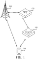
- FIG. 1 is a schematic diagram showing a mobile communication system according to an exemplary embodiment.
- the mobile communication system includes: an access network device 110, a WT 120, a WLAN AP 130, and a terminal 140.
- the access network device 110 is an eNB in LTE.
- the access network device 110 has a function of sending downlink data through an LTE link and a WLAN link, and the access network device 110 further has a function of receiving uplink data through the LTE link and the WLAN link.
- first downlink data and first uplink data are transmitted through the LTE link and second downlink data and second uplink data are transmitted through the WLAN link
- the access network device 110 can encapsulate data from a core network as first downlink data and second downlink data, send the first downlink data to the terminal through the LTE link, and send the second downlink data to the terminal through the WLAN link.
- the access network device 110 can further receive first uplink data through the LTE link, receive second uplink data through the WLAN link, aggregate the received first uplink data and second uplink data, and send the aggregated uplink data to the core network.
- the access network device 110 and the WT 120 are connected with each other in a one-to-one correspondence way, and in general cases, the access network device 110 may be fixed together with the WT 120, for example, they are formed on the same main board; or the access network device 110 and the WT 120 are connected with each other through optic fibers. As shown in FIG. 1 , the access network device 110 and the WT 120 are connected with each other correspondingly.
- the WT 120 has a function of sending second downlink data and receiving second uplink data.
- the WT 120 may be connected with multiple WLAN APs 130, and receive the second uplink data sent by each WLAN AP 130 or transmit the second downlink data to the WLAN APs 130 connected therewith.
- the number of the WTs 1020 and the WLAN APs 130 is not limited.
- the WLAN AP 130 has functions of sending the second downlink data and receiving the second uplink data.
- the WLAN AP 130 may be an electronic device such as wireless router or a wireless gateway.
- the WLAN AP 130 may be connected with multiple WTs 120 at the same time.
- the terminal 140 has functions of sending first uplink data and second uplink data and receiving first downlink data and second downlink data.
- the terminal 140 further has a LWA function, that is, when the received downlink data includes first downlink data and second downlink data, the terminal 140 can aggregate the first downlink data and the second downlink data.
- the terminal 140 further has functions of dividing the uplink data into first uplink data and second uplink data, sending the first uplink data to the access network device 110 through the LTE link, and sending the second uplink data to the access network device 110 through the WLAN link.
- the specific number and the specific position of the terminal 140 is not limited.
- FIG. 2 is a flow chart showing a data transmission method according to an exemplary embodiment. This embodiment is illustrated by taking that the data transmission method is applied to the mobile communication system shown in FIG. 1 as an example. The method includes following steps.
- an access network device configures path information for a terminal, an RRC connection being established between the access network device and the terminal, the path information being used for indicating a sending path of uplink data, and the sending path including an LTE link or a WLAN link.
- the access network device When the access network device receives data from a core network and issues the data to the terminal, it is possible to, according to a current link condition and a pre-configured sending strategy, determine which data is transmitted through the LTE link and which data is transmitted through the WLAN link. In this embodiment, in order to enable the terminal to make full use of the LTE link and the WLAN link, the access network device configures respective path information for the terminal establishing an RRC connection, thereby instructing the terminal to transmit uplink data through which link.
- Step 202 the access network device issues the path information to the terminal.
- the terminal After entering a cell within coverage of the access network device, the terminal establishes an RRC connection with the access network device, and receives system information broadcast by the access network device or RRC signaling sent (unicast) by the access network device.
- the access network device may add generated path information to the system information, and send the system information to respective terminals establishing the RRC connection by means of broadcasting.
- the access network device may further add generated path information to the RRC signaling, and send it through the RRC connection with the terminal.
- Step 203 the terminal receives the path information issued by the access network device.
- the terminal receives the system information broadcast by the access network device, and acquires the path information from the system information.
- the terminal receives the RRC signaling sent by the access network device, and acquires the path information from the RRC signaling.
- Step 204 the terminal determines a target sending path of uplink data according to the path information.
- the terminal determines, according to the acquired path information, a target sending path used when uplink data is sent.
- Step 205 the terminal sends the uplink data to the access network device according to the target sending path.
- the uplink data sent by the terminal to the access network device is uplink data aggregated and transmitted through LWA.
- the access network device after receiving LTE uplink data and WLAN uplink data uploaded by the terminal, needs to aggregate the LTE uplink data and the WLAN uplink data, to send the aggregated data to the core network.
- the terminal can transmit uplink data through an LTE link and a WLAN link, that is, the uplink data is sent by shunt, which avoids congestion of the LTE link caused by sending the uplink data only through the LTE link.
- transmitting some data by using the WLAN link improves data transmission efficiency.
- the access network device configures path information for the terminal establishing an RRC connection, and issues the path information to the terminal, such that the terminal receiving the path information can send uplink data according to a sending path indicated by the path information, which solves the problem in the related art that the terminal's sending uplink data only through a mobile communication link causes congestion of the mobile communication link and affects uplink data transmission efficiency and performance of the mobile communication system; achieves that a terminal sends uplink data based on a sending path configured by an access network device, makes full use of a mobile communication link and a WLAN link for data transmission, avoids congestion caused by use of a single link, and improves uplink data transmission efficiency and performance of a mobile communication system.
- step 201 and step 202 described above may be implemented as an information issuing method at a side of an access network device, and step 203 to step 205 described above may be implemented as a data sending method at a side of a terminal, which are no longer repeated herein.
- the access network device 110 in the mobile communication system may send system information to each terminal 140 in a cell by means of broadcasting, and through the system information, the terminal 140 may know network features and other information of the cell.
- the access network device may configure identical path information for respective terminals in the cell uniformly, and send the system information to the terminals by broadcast.
- An exemplary embodiment is used for description in the following.
- FIG. 3A is a flow chart of a data transmission method according to another exemplary embodiment. This embodiment is illustrated by taking that the data transmission method is applied to the mobile communication system shown in FIG. 1 as an example. The method includes following steps.
- the access network device sets the path information in a designated SIB of system information, the designated SIB being an original SIB or a new SIB of the system information.
- the system information broadcast by the access network device includes one Master Information Block (MIB) and multiple SIBs.
- the MIB includes a finite number of most important and most common transmission parameters, and is transmitted through a Physical Broadcast Channel (PBCH); the SIBs are used for carrying System Information (SI), and are transmitted through a Physical Downlink Shared Channel (PDSCH), in which a mapping relationship between the SIBs and the SI may be configured flexibly.
- the SIB of the system information includes the path information configured for the terminal.
- the access network device may acquire link conditions of the LTE link and the WLAN link and data transmission quality in real time by sending a reference signal, thus determining to instruct the terminal to send uplink data through which path. For example, when the link condition of the LTE link is worse (or the data transmission quality is worse) but the link condition of the WLAN link is better (or the data transmission quality is better), the access network device determines to instruct the terminal to send the uplink data through the WLAN link. It should be noted that, in other possible implementations, the access network device may further determine a path of sending the uplink data by the terminal according to a preset sending strategy (data having higher requirements for timeliness is transmitted through the LTE link, and data having lower requirements for timeliness is transmitted through the WLAN link), which is not limited in this embodiment.
- the access network device generates corresponding path information according to the determined sending path, and adds the path information to a designated SIB of the system information.
- the designated SIB may be an original SIB (e.g., SIB1) of the system information, and may also be a new SIB (e.g., SIB19, SIB20 and so on) of the system information.
- a data type of the path information is Boolean.
- the target sending path is the LTE link; and when the value of the path information is false, the target sending path is the WLAN link.
- the target sending path is the WLAN link; and when the value of the path information is false, the target sending path is the LTE link.
- the access network device may add a flag bit (Indication) to the SIB1, for indicating a sending path of the uplink data.
- a flag bit Indication
- the sending path of the uplink data is indicated to be the LTE link; and when the value of the flag bit is false, the sending path of the uplink data is indicated to be the WLAN link.
- Step 302 the access network device broadcasts the system information to respective terminals, in which the path information included in the system information broadcast to different terminals is identical.
- the access network device After setting the path information is completed, the access network device sends the system information to respective terminals establishing the RRC connection by means of broadcasting, in which the path information included in the system information broadcast to different terminals is identical, that is, in a cell within coverage of the access network device, path information received by respective terminals is identical.
- Step 303 the terminals receive the system information broadcast by the access network device.
- the terminals receive the system information, and acquire the path information included in the system information.
- the terminals detect whether the system information includes a designated SIB, and when the system information includes a designated SIB, further acquire path information included in the SIB.
- Step 304 the terminals determine a target sending path of the uplink data according to the path information included in the system information.
- the terminals further determine a target sending path of the uplink data according to the acquired path information.
- a data type of the path information included in the system information is boolean.
- the terminals determine the target sending path as the LTE link; and when the value of the path information is false, the terminals determine the target sending path as the WLAN link.
- the terminals determine the target sending path as the WLAN link; and when the value of the path information is false, the terminals determine the target sending path as the LTE link.
- the terminals may use a corresponding interpretation manner to determine a target sending path indicated by the path information, which is not limited in this embodiment.
- Step 305 the terminals send the uplink data to the access network device according to the target sending path.
- the terminals When needing to send the uplink data to the access network device, the terminals, after encapsulating the uplink data, send the data through a corresponding sending path, thus implementing shunt transmission of the uplink data.
- the terminals when the path information instructs the terminals to send uplink data having higher requirements for timeliness through the LTE link and to send uplink data having lower requirements for timeliness through the WLAN link, the terminals encapsulate the uplink data having higher requirements for timeliness as an LTE data packet and sends the LTE data packet to the access network device through the LTE link; at the same time, the terminals encapsulate the uplink data having lower requirements for timeliness as a WLAN data packet and send the WLAN data packet to the access network device through the WLAN link.
- the access network device configures path information for terminals establishing an RRC connection, and issues the path information to the terminals, such that the terminals receiving the path information can send uplink data according to a sending path indicated by the path information, which solves the problem in the related art that the terminals' sending uplink data only through a mobile communication link causes congestion of the mobile communication link and affects uplink data transmission efficiency and performance of the mobile communication system; achieves that terminals send uplink data based on a sending path configured by an access network device, makes full use of a mobile communication link and a WLAN link for data transmission, avoids congestion caused by use of a single link, and improves uplink data transmission efficiency and performance of a mobile communication system.
- the access network device adds path information to system information and broadcasts the system information to respective terminals, achieving uniform configuration for all the terminals in a cell, having higher configuration efficiency, and reducing an upgrade cost of the whole mobile communication system.
- the terminal when path information is not configured in the received system information, the terminal sends the uplink data according to a default path (e.g., the LTE path), and when path information is configured in the received system information, the terminal transmits the uplink data according to a sending path indicated by the path information.
- a default path e.g., the LTE path
- the terminal transmits the uplink data according to a sending path indicated by the path information.
- the method may further include the following steps.
- Step 306 the terminal detects whether the path information issued by the access network device exists.
- the terminal detects whether the system information broadcast by the access network device includes a designated SIB. If the system information does not include the designated SIB, the following step 307 is performed; if the system information includes the designated SIB, the terminal further detects whether the designated SIB includes a designated flag bit (for indicating path information), and when the designated SIB includes the designated flag bit, step 304 is performed; and when the designated SIB does not include the designated flag bit, the following step 307 is performed.
- a designated flag bit for indicating path information
- Step 307 when the path information issued by the access network device does not exist, the terminal sends the uplink data through the LTE link.
- the terminal When it is detected that the system information does not include the path information, the terminal sends the uplink data through the LTE link (default path).
- step 301 and step 302 described above may be implemented as an information issuing method at a side of an access network device, and step 303 to step 307 described above may be implemented as a data sending method at a side of a terminal, which are no longer repeated herein.
- the access network device may configure different path information for different terminals, and send the path information to the corresponding terminal by unicast RRC signaling. Description is given below by using an exemplary embodiment.
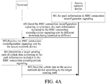
- FIG. 4A is a flow chart of a data transmission method according to a further exemplary embodiment. This embodiment is illustrated by taking that the data transmission method is applied to the mobile communication system shown in FIG. 1 as an example. The method includes following steps.
- Step 401 the access network device sets path information in RRC connection reconfiguration signaling.
- the RRC connection reconfiguration signaling is used for modifying the RRC connection between the access network device and the terminal, specifically implementing measurement configuration modification, switching radio bearer, configuring radio bearer, data radio bearer, transmission channels, physical channels and so on.
- the access network device configures the path information in the RRC connection reconfiguration signaling.
- the access network device may configure different path information for different terminals according to traffic use conditions, network support conditions and other information of respective terminals in the cell, and add the path information to the RRC connection reconfiguration signaling, facilitating subsequent sending of the path information to the corresponding terminals.
- a data type of the path information is boolean.
- the target sending path is the LTE link; and when the value of the path information is false, the target sending path is the WLAN link.
- the target sending path is the WLAN link; and when the value of the path information is false, the target sending path is the LTE link.
- the access network device may acquire a traffic use condition of the terminal.
- the traffic use condition indicates that the remaining traffic of the terminal is greater than a threshold
- the target sending path configured by the access network device for the terminal is an LTE link
- a value of the path information in the RRC connection reconfiguration signaling is set as true.
- the target sending path configured by the access network device for the terminal is a WLAN link
- the value of the path information in the RRC connection reconfiguration signaling is set as false.
- Step 402 the access network device sends the RRC connection reconfiguration signaling to terminals, in which the path information included in the RRC connection reconfiguration signaling sent to different terminals is identical or different.
- the access network device After setting the path information is completed in the RRC connection reconfiguration signaling, the access network device sends the RRC connection reconfiguration signaling to the corresponding terminal by unicast.
- the path information included in the RRC connection reconfiguration signaling sent to different terminals is identical or different, that is, the sending paths of the uplink data configured by the access network device for respective terminals in the cell are identical or different.
- the access network device may further combine broadcast with unicast to uniformly configure path information for a large number of terminals in the cell by broadcast and then configure path information for a small number of terminals in the cell separately by unicast (in which the priority of the path information configured by unicast is higher than that of the path information configured by broadcast, that is, the terminal preferentially transmits the uplink data according to the path information configured by unicast), which is not limited in the present disclosure.
- Step 403 the terminals receive the RRC connection reconfiguration signaling sent by the access network device.
- the terminals receive the RRC connection reconfiguration signaling sent by the access network device, and acquire the path information included in the RRC connection reconfiguration signaling.
- Step 404 the terminals determine the target sending path of uplink data according to the path information included in the RRC connection reconfiguration signaling.
- the terminals determine the sending path of the uplink data according to the acquired path information.
- a data type of the path information included in the RRC connection reconfiguration signaling is boolean.
- the terminals determine the target sending path as the LTE link; and when the value of the path information is false, the terminals determine the target sending path as the WLAN link.
- the terminals determine the target sending path as the WLAN link; and when the value of the path information is false, the terminals determine the target sending path as the LTE link.
- the terminals may use a corresponding interpretation manner to determine a target sending path indicated by the path information, which is not limited in this embodiment.
- Step 405 the terminals send the uplink data to the access network device according to the target sending path.
- the terminals when needing to send the uplink data to the access network device, the terminals, after encapsulating the uplink data, send the data through a corresponding sending path, thus implementing shunt transmission of the uplink data.
- the access network device configures path information for terminals establishing an RRC connection, and issues the path information to the terminals, such that the terminals receiving the path information can send uplink data according to a sending path indicated by the path information, which solves the problem in the related art that the terminals' sending uplink data only through a mobile communication link causes congestion of the mobile communication link and affects uplink data transmission efficiency and performance of the mobile communication system, achieves that the terminals send uplink data based on a sending path configured by an access network device, makes full use of a mobile communication link and a WLAN link for data transmission, avoids congestion caused by use of a single link, and improves uplink data transmission efficiency and performance of a mobile communication system.
- the access network device adds path information to the RRC connection reconfiguration signaling, and sends the RRC connection reconfiguration signaling to corresponding terminals by unicast, thus implementing targeted configuration for terminals in the cell.
- the terminals when path information is not configured in the received RRC connection reconfiguration signaling, the terminals send the uplink data according to a default path (e.g., the LTE path), and when path information is configured in the received RRC connection reconfiguration signaling, the terminals transmit the uplink data according to a sending path indicated by the path information.
- a default path e.g., the LTE path
- path information is configured in the received RRC connection reconfiguration signaling
- the terminals transmit the uplink data according to a sending path indicated by the path information.
- the method may further include the following steps.
- Step 406 the terminals detect whether the path information issued by the access network device exists.
- the terminals detect whether the RRC connection reconfiguration signaling sent by the access network device includes path information. If the RRC connection reconfiguration signaling includes the path information, step 404 is performed; and if the RRC connection reconfiguration signaling does not include the path information, the following step 407 is performed.
- Step 407 when the path information issued by the access network device does not exist, the terminals send the uplink data through the LTE link.
- the terminals When detecting that the RRC connection reconfiguration signaling does not include the path information, the terminals send the uplink data through the LTE link (default path).
- step 401 and step 402 may be implemented as an information issuing method at a side of an access network device, and step 403 to step 407 described above may be implemented as a data sending method at a side of a terminal, which are no longer repeated herein.
- FIG. 5 is a block diagram of an information issuing apparatus according to an exemplary embodiment.
- the information issuing apparatus may be implemented as whole or part of the access network device 110 in FIG. 1 through a dedicated hardware circuit or a combination of software and hardware.
- the information issuing apparatus includes an information configuration module 510 and an information issuing module 520.
- the information configuration module 510 is configured to configure path information for a terminal, an RRC connection being established between the access network device and the terminal, the path information being used for indicating a sending path of uplink data, and the sending path including a mobile communication link or a WLAN link; and
- the information issuing module 520 is configured to issue the path information to the terminal, the terminal being configured to determine a target sending path of uplink data according to the path information, and send the uplink data to the access network device according to the target sending path.
- the information configuration module 510 includes a first configuration sub-module 511.
- the first configuration sub-module 511 is configured to set the path information in a designated SIB of system information, the designated SIB being an original SIB or a new SIB of the system information.
- the information issuing module 520 includes a first issuing sub-module 521.
- the first issuing sub-module 521 is configured to broadcast the system information to respective terminals, the terminals being configured to determine the target sending path according to the path information included in the designated SIB of the system information, and send the uplink data to the access network device through the target sending path, in which the path information included in the system information broadcast to different terminals is identical.
- the information configuration module 510 includes a second configuration sub-module 512.
- the second configuration sub-module 512 is configured to set the path information in RRC connection reconfiguration signaling.
- the information issuing module 520 includes a second issuing sub-module 522.
- the second issuing sub-module 522 is configured to send the RRC connection reconfiguration signaling to the terminals, the terminals being configured to determine the target sending path according to the path information included in the RRC connection reconfiguration signaling, and send the uplink data to the access network device through the target sending path, in which the path information included in the RRC connection reconfiguration signaling sent to different terminals are identical or different.
- a data type of the path information is boolean.
- the target sending path is the mobile communication link; and when the value of the path information is false, the target sending path is the WLAN link.
- the target sending path is the WLAN link; and when the value of the path information is false, the target sending path is the mobile communication link.
- an access network device configures path information for terminals establishing an RRC connection, and issues the path information to the terminals, such that the terminals receiving the path information can send uplink data according to a sending path indicated by the path information, which solves the problem in the related art that the terminals' sending uplink data only through a mobile communication link causes congestion of the mobile communication link and affects uplink data transmission efficiency and performance of the mobile communication system; achieves that terminals send uplink data based on a sending path configured by an access network device, makes full use of a mobile communication link and a WLAN link for data transmission, avoids congestion caused by use of a single link, and improves uplink data transmission efficiency and performance of a mobile communication system.
- the access network device adds path information to system information and broadcasts the system information to respective terminals, achieving uniform configuration for all the terminals in a cell, having higher configuration efficiency, and reducing an upgrade cost of the whole mobile communication system.
- the access network device adds path information to the RRC connection reconfiguration signaling, and sends the RRC connection reconfiguration signaling to corresponding terminals by unicast, thus implementing targeted configuration for terminals in the cell.
- FIG. 6 is a block diagram of a data sending apparatus according to an exemplary embodiment.
- the data sending apparatus may be implemented as whole or part of the terminal 140 in FIG. 1 through a dedicated hardware circuit or a combination of software and hardware.
- the data sending apparatus includes an information receiving module 610, a path determining module 620, and a first data sending module 630.
- the information receiving module 610 is configured to receive path information issued by an access network device, an RRC connection being established between the access network device and the terminal, the path information being used for indicating a sending path of uplink data, and the sending path including a mobile communication link or a WLAN link;
- the path determining module 620 is configured to determine a target sending path of uplink data according to the path information.
- the first data sending module 630 is configured to send the uplink data to the access network device according to the target sending path.
- the information receiving module 610 includes a first receiving sub-module 611.
- the first receiving sub-module 611 is configured to receive system information broadcast by the access network device, a designated System Information Block (SIB) of the system information including the path information, and the designated SIB being an original SIB or a new SIB of the system information.
- SIB System Information Block
- the information receiving module 610 includes a second receiving sub-module 612.
- the second receiving sub-module 612 is configured to receive RRC connection reconfiguration signaling sent by the access network device, the RRC connection reconfiguration signaling including the path information, and the path information included in the RRC connection reconfiguration signaling sent to different terminals being identical or different.
- a data type of the path information is boolean.
- the path determining module 620 is configured to determine the target sending path as the mobile communication link when a value of the path information is true, determine the target sending path as the WLAN link when the value of the path information is false. Or, the path determining module is configured to determine the target sending path as the WLAN link when a value of the path information is true, and determine the target sending path as the mobile communication link when the value of the path information is false.
- the apparatus further includes a detecting module 640 and a second data sending module 650.
- the detecting module 640 is configured to detect whether the path information issued by the access network device exists.
- the path determining module 620 is configured to determine a target sending path of uplink data according to the path information when the path information issued by the access network device exists.
- the second data sending module 650 is configured to send the uplink data through the LTE link, when the path information issued by the access network device does not exist.
- an access network device configures path information for terminals establishing an RRC connection, and issues the path information to the terminals, such that the terminals receiving the path information can send uplink data according to a sending path indicated by the path information, which solves the problem in the related art that the terminals' sending uplink data only through a mobile communication link causes congestion of the mobile communication link and affects uplink data transmission efficiency and performance of the mobile communication system; achieves that terminals send uplink data based on a sending path configured by an access network device, makes full use of a mobile communication link and a WLAN link for data transmission, avoids congestion caused by use of a single link, and improves uplink data transmission efficiency and performance of a mobile communication system.
- the access network device adds path information to system information and broadcasts the system information to respective terminals, achieving uniform configuration for all the terminals in a cell, having higher configuration efficiency, and reducing an upgrade cost of the whole mobile communication system.
- the access network device adds path information to the RRC connection reconfiguration signaling, and sends the RRC connection reconfiguration signaling to corresponding terminals by unicast, thus implementing targeted configuration for terminals in the cell.
- FIG. 7 is a schematic diagram of an access network device 110 according to an exemplary embodiment.
- the access network device 110 includes: a processor 71, a memory 72, a transmitter 73, and a receiver 74.
- the processor 71 is connected with the memory 72.
- the processor 71 includes one or more processing cores, and the processor 71 executes various functional applications and information processing by running software programs and units.
- the memory 72 may be configured to store one or more program instructions, the one or more program instructions being used for implementing at least one software program and module.
- the memory 72 may store an operating system 74 and an application module 75 required by at least one function.
- the processor 71 is configured to execute the program instructions in the memory 72, to implement the steps performed by the access network device 110 as in the above method embodiments.
- the memory 72 may be implemented using any type of volatile or non-volatile memory devices, or a combination thereof, such as a static random access memory (SRAM), an electrically erasable programmable read-only memory (EEPROM), an erasable programmable read-only memory (EPROM), a programmable read-only memory (PROM), a read-only memory (ROM), a magnetic memory, a flash memory, a magnetic or optical disk.
- SRAM static random access memory
- EEPROM electrically erasable programmable read-only memory
- EPROM erasable programmable read-only memory
- PROM programmable read-only memory
- ROM read-only memory
- magnetic memory a magnetic memory
- flash memory a flash memory
- magnetic or optical disk a magnetic or optical disk.
- the transmitter 73 includes a modem unit and a Multiple Input Multiple Output (MIMO) antenna, in which the MIMO antenna is an antenna that supports transmitting and receiving of multiple antenna ports.
- MIMO antenna includes at least two transmitting antennas.
- the transmitter 73 is configured to implement data and signaling transmission.
- the receiver 76 includes a structure identical with or similar to that of the transmitter 73.
- the receiver 76 includes a modem unit and a MIMO antenna, in which the MIMO antenna includes at least two receiving antennas.
- the structure of the access network device 110 shown in FIG. 7 does not limit the access network device 110, which may include more or fewer components than those illustrated or combine some components, or have different configuration of components.
- FIG. 8 is a schematic diagram of a terminal 140 according to an exemplary embodiment.
- the terminal 140 includes: a processor 81, a memory 82, a transmitter 83, and a receiver 84.
- the processor 81 is connected with the memory 82.
- the processor 81 includes one or more processing cores, and the processor 81 executes various functional applications and information processing by running software programs and units.
- the memory 82 may be configured to store one or more program instructions, the one or more program instructions being used for implementing at least one software program and module.
- the memory 82 may store an operating system 84 and an application module 85 required by at least one function.
- the processor 81 is configured to execute the program instructions in the memory 82, to implement the steps performed by the terminal 140 as in the above method embodiments.
- the memory 82 may be implemented using any type of volatile or non-volatile memory devices, or a combination thereof, such as a static random access memory (SRAM), an electrically erasable programmable read-only memory (EEPROM), an erasable programmable read-only memory (EPROM), a programmable read-only memory (PROM), a read-only memory (ROM), a magnetic memory, a flash memory, a magnetic or optical disk.
- SRAM static random access memory
- EEPROM electrically erasable programmable read-only memory
- EPROM erasable programmable read-only memory
- PROM programmable read-only memory
- ROM read-only memory
- magnetic memory a magnetic memory
- flash memory a flash memory
- magnetic or optical disk a magnetic or optical disk.
- the transmitter 83 includes a modem unit and a Multiple Input Multiple Output (MIMO) antenna, in which the MIMO antenna is an antenna that supports transmitting and receiving of multiple antenna ports.
- MIMO antenna includes at least two transmitting antennas.
- the transmitter 83 is configured to implement data and signaling transmission.
- the receiver 86 includes a structure identical with or similar to that of the transmitter 83.
- the receiver 86 includes a modem unit and a MIMO antenna, in which the MIMO antenna includes at least two receiving antennas.
- the structure of the terminal 140 shown in FIG. 8 does not limit the terminal 140, which may include more or fewer components than those illustrated or combine some components, or have different configuration of components.
Landscapes
- Engineering & Computer Science (AREA)
- Computer Networks & Wireless Communication (AREA)
- Signal Processing (AREA)
- Computer Security & Cryptography (AREA)
- Mobile Radio Communication Systems (AREA)
Abstract
Description
- The present disclosure relates to the field of communications, and more particularly, to an information issuing method, a data sending method, as well as corresponding apparatus and system.
- Long Term Evolution - Wireless Local Area Network Aggregations (LTE-WLAN Aggregations, LWA) is a technology that transmits data by using an LTE network and a WLAN network at the same time.
- When an access network device transmits downlink data by using LWA, an eNB (a base), while transmitting a part of the downlink data to a terminal via the LTE network, transmits the remaining part of the downlink data to the terminal via the WLAN network according to a Medium Access Control (MAC) address of a UE (a user). The terminal aggregates the two received parts of data, thereby implementing downlink transmission of the data.
- The present disclosure provides an information issuing method, a data sending method, as well as corresponding apparatus and system. The technical solutions are as follows.
- In a first aspect, an information issuing method is provided, including:
- configuring, by an access network device, path information for a terminal, a Radio Resource Control (RRC) connection being established between the access network device and the terminal, the path information being used for indicating a sending path of uplink data, and the sending path including a mobile communication link or a WLAN link; and
- issuing, by the access network device, the path information to the terminal, the terminal being configured to determine a target sending path of uplink data according to the path information, and send the uplink data to the access network device according to the target sending path.
- In an alternative embodiment, configuring path information for a terminal includes:
setting, by the access network device, the path information in a designated System Information Block (SIB) of system information, the designated SIB being an original SIB or a new SIB of the system information. - In an alternative embodiment, issuing the path information to the terminal includes:
- broadcasting, by the access network device, the system information to respective terminals, the terminals being configured to determine the target sending path according to the path information included in the designated SIB of the system information, and send the uplink data to the access network device through the target sending path;
- wherein the path information included in the system information broadcast to different terminals is identical.
- In an alternative embodiment, configuring path information for a terminal includes:
setting, by the access network device, the path information in RRC connection reconfiguration signaling. - In an alternative embodiment, issuing the path information to the terminal includes:
- sending, by the access network device, the RRC connection reconfiguration signaling to the terminals, the terminals being configured to determine the target sending path according to the path information included in the RRC connection reconfiguration signaling, and send the uplink data to the access network device through the target sending path;
- wherein the path information included in the RRC connection reconfiguration signaling sent to different terminals is identical or different.
- In an alternative embodiment, a data type of the path information is boolean; and
when a value of the path information is true, the target sending path is the mobile communication link; and when the value of the path information is false, the target sending path is the WLAN link;
or
when a value of the path information is true, the target sending path is the WLAN link; and when the value of the path information is false, the target sending path is the mobile communication link. - In a second aspect, a data sending method is provided, including:
- receiving, by a terminal, path information issued by an access network device, an RRC connection being established between the access network device and the terminal, the path information being used for indicating a sending path of uplink data, and the sending path including a mobile communication link or a WLAN link;
- determining, by the terminal, a target sending path of uplink data according to the path information; and
- sending, by the terminal, the uplink data to the access network device according to the target sending path.
- In an alternative embodiment, receiving path information issued by an access network device includes:
receiving, by the terminal, system information broadcast by the access network device, a designated SIB of the system information including the path information, and the designated SIB being an original SIB or a new SIB of the system information. - In an alternative embodiment, receiving path information issued by an access network device includes:
receiving, by the terminal, RRC connection reconfiguration signaling sent by the access network device, the RRC connection reconfiguration signaling including the path information, and the path information included in the RRC connection reconfiguration signaling sent to different terminals being identical or different. - In an alternative embodiment, a data type of the path information is boolean; and
when a value of the path information is true, the terminals determine the target sending path as the mobile communication link; and when the value of the path information is false, the terminals determine the target sending path as the WLAN link;
or
when a value of the path information is true, the terminals determine the target sending path as the WLAN link; and when the value of the path information is false, the terminals determine the target sending path as the mobile communication link. - In an alternative embodiment, the method further includes:
- detecting, by the terminal, whether the path information issued by the access network device exists;
- when the path information issued by the access network device exists, performing, by the terminal, the step of determining a target sending path of uplink data according to the path information; and
- when the path information issued by the access network device does not exist, sending, by the terminal, the uplink data through the mobile communication link.
- In a third aspect, an information issuing apparatus is provided, including:
- an information configuration module, configured to configure path information for a terminal, an RRC connection being established between the access network device and the terminal, the path information being used for indicating a sending path of uplink data, and the sending path including a mobile communication link or a WLAN link; and
- an information issuing module, configured to issue the path information to the terminal, the terminal being configured to determine a target sending path of uplink data according to the path information, and send the uplink data to the access network device according to the target sending path.
- In an alternative embodiment, the information configuration module includes:
a first configuration sub-module, configured to set the path information in a designated SIB of system information, the designated SIB being an original SIB or a new SIB of the system information. - In an alternative embodiment, the information issuing module includes:
- a first issuing sub-module, configured to broadcast the system information to respective terminals, the terminals being configured to determine the target sending path according to the path information included in the designated SIB of the system information, and send the uplink data to the access network device through the target sending path;
- where the path information included in the system information broadcast to different terminals is identical.
- In an alternative embodiment, the information configuration module includes:
a second configuration sub-module, configured to set the path information in RRC connection reconfiguration signaling. - In an alternative embodiment, the information issuing module includes:
- a second issuing sub-module, configured to send the RRC connection reconfiguration signaling to the terminals, the terminals being configured to determine the target sending path according to the path information included in the RRC connection reconfiguration signaling, and send the uplink data to the access network device through the target sending path;
- wherein the path information included in the RRC connection reconfiguration signaling sent to different terminals is identical or different.
- In an alternative embodiment, a data type of the path information is boolean; and
when a value of the path information is true, the target sending path is the mobile communication link; and when the value of the path information is false, the target sending path is the WLAN link;
or
when a value of the path information is true, the target sending path is the WLAN link; and when the value of the path information is false, the target sending path is the mobile communication link. - In a fourth aspect, a data sending apparatus is provided, including:
- an information receiving module, configured to receive path information issued by an access network device, an RRC connection being established between the access network device and the terminal, the path information being used for indicating a sending path of uplink data, and the sending path including a mobile communication link or a WLAN link;
- a path determining module, configured to determine a target sending path of uplink data according to the path information; and
- a first data sending module, configured to send the uplink data to the access network device according to the target sending path.
- In an alternative embodiment, the information receiving module includes:
a first receiving sub-module, configured to receive system information broadcast by the access network device, a designated SIB of the system information including the path information, and the designated SIB being an original SIB or a new SIB of the system information. - In an alternative embodiment, the information receiving module includes:
a second receiving sub-module, configured to receive RRC connection reconfiguration signaling sent by the access network device, the RRC connection reconfiguration signaling including the path information, and the path information included in the RRC connection reconfiguration signaling sent to different terminals being identical or different. - In an alternative embodiment, a data type of the path information is boolean; and
the path determining module is configured to determine the target sending path as the mobile communication link when a value of the path information is true, and determine the target sending path as the WLAN link when the value of the path information is false;
or
the path determining module is configured to determine the target sending path as the WLAN link when a value of the path information is true, and determine the target sending path as the mobile communication link when the value of the path information is false. - In an alternative embodiment, the apparatus further includes:
- a detecting module, configured to detect whether the path information issued by the access network device exists , in which the path determining module is configured to determine a target sending path of uplink data according to the path information when the path information issued by the access network device exists; and
- a second data sending module, configured to send the uplink data through the mobile communication link when the path information issued by the access network device does not exist.
- In a fifth aspect, an access network device is provided, including:
- a processor; and
- a memory configured to store instructions executable by the processor;
- wherein the processor is configured to:
- configure path information for a terminal, an RRC connection being established between the access network device and the terminal, the path information being used for indicating a sending path of uplink data, and the sending path including a mobile communication link or a WLAN link; and
- issue the path information to the terminal, the terminal being configured to determine a target sending path of uplink data according to the path information, and send the uplink data to the access network device according to the target sending path.
- In a sixth aspect, a terminal is provided, including:
- a processor; and
- a memory configured to store instructions executable by the processor;
- wherein the processor is configured to:
- receive path information issued by an access network device, an RRC connection being established between the access network device and the terminal, the path information being used for indicating a sending path of uplink data, and the sending path including a mobile communication link or a WLAN link;
- determine a target sending path of uplink data according to the path information; and
- send the uplink data to the access network device according to the target sending path.
- In a seventh aspect, a mobile communication system is provided, including: an access network device and at least one terminal establishing an RRC connection with the access network device;
the access network device including the information issuing apparatus as stated in the third aspect; and the terminal including the data sending apparatus as stated in the fourth aspect;
or
the access network device including the access network device as stated in the fifth aspect; and the terminal including the terminal as stated in the sixth aspect. - The technical solutions provided in embodiments of the present disclosure may include the following beneficial effects.
- The access network device configures path information for the terminal that establishes the RRC connection with the access network device, and issues the path information to the terminal, such that the terminal receiving the path information can send uplink data according to a sending path indicated by the path information, which solves the problem in the related art that the terminal's sending uplink data only through a mobile communication link causes congestion of the mobile communication link and affects uplink data transmission efficiency and performance of the mobile communication system; achieves that a terminal sends uplink data based on a sending path configured by an access network device, makes full use of a mobile communication link and a WLAN link for data transmission, avoids congestion caused by use of a single link, and improves uplink data transmission efficiency and performance of a mobile communication system.
- It should be understood that the foregoing general description and the later detailed description are merely exemplary, and cannot limit the present disclosure.
- The accompanying drawings, which are incorporated in and constitute a part of this specification, illustrate embodiments consistent with the invention and, together with the description, serve to explain the principles of the invention.
-
FIG. 1 is a schematic diagram showing a mobile communication system according to an exemplary embodiment; -
FIG. 2 is a flow chart showing a data transmission method according to an exemplary embodiment; -
FIG. 3A is a flow chart of a data transmission method according to another exemplary embodiment; -
FIG. 3B is a flow chart of a data transmission method according to another exemplary embodiment; -
FIG. 4A is a flow chart of a data transmission method according to a further exemplary embodiment; -
FIG. 4B is a flow chart of a data transmission method according to a further exemplary embodiment; -
FIG. 5 is a block diagram of an information issuing apparatus according to an exemplary embodiment; -
FIG. 6 is a block diagram of a data sending apparatus according to an exemplary embodiment; -
FIG. 7 is a schematic diagram of anaccess network device 110 according to an exemplary embodiment; and -
FIG. 8 is a schematic diagram of a terminal 140 according to an exemplary embodiment. - Reference will now be made in detail to exemplary embodiments, examples of which are illustrated in the accompanying drawings. The following description refers to the accompanying drawings in which the same numbers in different drawings represent the same or similar elements unless otherwise represented. The implementations set forth in the following description of exemplary embodiments do not represent all implementations consistent with the present disclosure. Instead, they are merely examples of apparatuses and methods consistent with aspects related to the present disclosure as recited in the appended claims.
- "Unit" mentioned herein refers to a program or instruction stored in a memory and capable of implementing some functions; "module" mentioned herein refers to a functional structure divided according to logic, and the "module" can be implemented by pure hardware, or a combination of software and hardware.
- "Multiple" mentioned herein refers to two or more. "And/or" describes an association relationship of associated objects and indicates that three relationships may exist, for example, A and/or B may indicate the following three situations: A exists alone, A and B exist at the same time, and B exists alone. The symbol "/" generally indicates that former and latter associated objects are in an "or" relationship.
- For ease of understanding, terms involved in the embodiments of the present disclosure are explained in the following.
- Access network device: a network element configured to provide a mobile communication network accessing function in a mobile communication system.
- In different mobile communication systems, the access network device has identical or similar functions, but may have different names or specific implementations. Optionally, the access network device is a Base Transceiver Station (BTS) in a Global System for Mobile communication (GSM) system or Code Division Multiple Access (CDMA) system. Optionally, the access network device is a base station (NodeB) in a Universal Mobile Telecommunications System (UMTS). Optionally, the access network device is an evolutional base station (evolutional Node B, eNB or e-NodeB) in Long Term Evolution (LTE) system. In actual networking, specific implementations of the access network device may be a macro base station, a micro base station, a femto base station, a repeater and so on.
- Terminal: an electronic device used by users in a mobile communication system.
- In different mobile communication systems, the terminal has identical or similar functions, but may have different names or specific implementations. Optionally, the terminal may be a Subscriber Unit, a Subscriber Station, a Mobile Station, a Mobile, a Remote Station, an Access Point, a Remote Terminal, an Access Terminal, a User Terminal, a User Agent, a User Device, or a User Equipment (UE). In actual networking, specific implementations of the terminal may be a mobile phone, a tablet computer, a smart household appliance, a smart instrument, an Internet of Things device, an Internet of Vehicles device and so on. In embodiments of the present disclosure, the specific number and the specific installation position of the terminals is not limited.
- WLAN Termination (WT): a logical network element defined in a LWA system, which has a function of managing a WLAN wireless access point (AP).
- In the LWA system, a WT and an eNB are connected with each other in a one-to-one correspondence way, and are usually fixed together. One WT can be connected with multiple WLAN APs at the same time, and responsible for monitoring and managing each WLAN AP connected therewith. In the LWA system, when the access network device transmits a downlink data packet to the terminal through a WLAN link, or receives, through the WLAN link, an uplink data packet transmitted by the terminal, the downlink data packet and the uplink data packet both pass through the WT connected with the access network device.
- AP: a node configured to provide, in a WLAN, WLAN access capability to the terminal.
- For ease of description, in embodiments of the present disclosure, schematic description is made by taking that the access network device is an eNB and an LTE link and a WLAN link are included between the access network device and the terminal as an example, which does not limit the present disclosure.
-
FIG. 1 is a schematic diagram showing a mobile communication system according to an exemplary embodiment. The mobile communication system includes: anaccess network device 110, aWT 120, aWLAN AP 130, and a terminal 140. - Optionally, the
access network device 110 is an eNB in LTE. Theaccess network device 110 has a function of sending downlink data through an LTE link and a WLAN link, and theaccess network device 110 further has a function of receiving uplink data through the LTE link and the WLAN link. Suppose that first downlink data and first uplink data are transmitted through the LTE link and second downlink data and second uplink data are transmitted through the WLAN link, then theaccess network device 110 can encapsulate data from a core network as first downlink data and second downlink data, send the first downlink data to the terminal through the LTE link, and send the second downlink data to the terminal through the WLAN link. Theaccess network device 110 can further receive first uplink data through the LTE link, receive second uplink data through the WLAN link, aggregate the received first uplink data and second uplink data, and send the aggregated uplink data to the core network. - The
access network device 110 and theWT 120 are connected with each other in a one-to-one correspondence way, and in general cases, theaccess network device 110 may be fixed together with theWT 120, for example, they are formed on the same main board; or theaccess network device 110 and theWT 120 are connected with each other through optic fibers. As shown inFIG. 1 , theaccess network device 110 and theWT 120 are connected with each other correspondingly. - The
WT 120 has a function of sending second downlink data and receiving second uplink data. TheWT 120 may be connected withmultiple WLAN APs 130, and receive the second uplink data sent by eachWLAN AP 130 or transmit the second downlink data to theWLAN APs 130 connected therewith. In embodiments of the present disclosure, the number of the WTs 1020 and theWLAN APs 130 is not limited. - The
WLAN AP 130 has functions of sending the second downlink data and receiving the second uplink data. In actual networking, theWLAN AP 130 may be an electronic device such as wireless router or a wireless gateway. TheWLAN AP 130 may be connected withmultiple WTs 120 at the same time. - The terminal 140 has functions of sending first uplink data and second uplink data and receiving first downlink data and second downlink data. In addition, the terminal 140 further has a LWA function, that is, when the received downlink data includes first downlink data and second downlink data, the terminal 140 can aggregate the first downlink data and the second downlink data. The terminal 140 further has functions of dividing the uplink data into first uplink data and second uplink data, sending the first uplink data to the
access network device 110 through the LTE link, and sending the second uplink data to theaccess network device 110 through the WLAN link. In embodiments of the present disclosure, the specific number and the specific position of the terminal 140 is not limited. -
FIG. 2 is a flow chart showing a data transmission method according to an exemplary embodiment. This embodiment is illustrated by taking that the data transmission method is applied to the mobile communication system shown inFIG. 1 as an example. The method includes following steps. - In Step 201, an access network device configures path information for a terminal, an RRC connection being established between the access network device and the terminal, the path information being used for indicating a sending path of uplink data, and the sending path including an LTE link or a WLAN link.
- When the access network device receives data from a core network and issues the data to the terminal, it is possible to, according to a current link condition and a pre-configured sending strategy, determine which data is transmitted through the LTE link and which data is transmitted through the WLAN link. In this embodiment, in order to enable the terminal to make full use of the LTE link and the WLAN link, the access network device configures respective path information for the terminal establishing an RRC connection, thereby instructing the terminal to transmit uplink data through which link.
- In
Step 202, the access network device issues the path information to the terminal. - After entering a cell within coverage of the access network device, the terminal establishes an RRC connection with the access network device, and receives system information broadcast by the access network device or RRC signaling sent (unicast) by the access network device.
- In an alternative embodiment, the access network device may add generated path information to the system information, and send the system information to respective terminals establishing the RRC connection by means of broadcasting.
- In an alternative embodiment, the access network device may further add generated path information to the RRC signaling, and send it through the RRC connection with the terminal.
- In
Step 203, the terminal receives the path information issued by the access network device. - In an alternative embodiment, the terminal receives the system information broadcast by the access network device, and acquires the path information from the system information.
- In an alternative embodiment, the terminal receives the RRC signaling sent by the access network device, and acquires the path information from the RRC signaling.
- In
Step 204, the terminal determines a target sending path of uplink data according to the path information. - The terminal determines, according to the acquired path information, a target sending path used when uplink data is sent.
- In
Step 205, the terminal sends the uplink data to the access network device according to the target sending path. - It should be noted that the uplink data sent by the terminal to the access network device is uplink data aggregated and transmitted through LWA. In other words, the access network device, after receiving LTE uplink data and WLAN uplink data uploaded by the terminal, needs to aggregate the LTE uplink data and the WLAN uplink data, to send the aggregated data to the core network.
- Different from the terminal's sending uplink data to the access network device only through an LTE link in the related art, based on the path information configured by the access network device, the terminal can transmit uplink data through an LTE link and a WLAN link, that is, the uplink data is sent by shunt, which avoids congestion of the LTE link caused by sending the uplink data only through the LTE link. At the same time, transmitting some data by using the WLAN link improves data transmission efficiency.
- In summary, with the data transmission method according to this embodiment, the access network device configures path information for the terminal establishing an RRC connection, and issues the path information to the terminal, such that the terminal receiving the path information can send uplink data according to a sending path indicated by the path information, which solves the problem in the related art that the terminal's sending uplink data only through a mobile communication link causes congestion of the mobile communication link and affects uplink data transmission efficiency and performance of the mobile communication system; achieves that a terminal sends uplink data based on a sending path configured by an access network device, makes full use of a mobile communication link and a WLAN link for data transmission, avoids congestion caused by use of a single link, and improves uplink data transmission efficiency and performance of a mobile communication system.
- It should be noted that step 201 and step 202 described above may be implemented as an information issuing method at a side of an access network device, and step 203 to step 205 described above may be implemented as a data sending method at a side of a terminal, which are no longer repeated herein.
- As shown in
FIG. 1 , theaccess network device 110 in the mobile communication system may send system information to each terminal 140 in a cell by means of broadcasting, and through the system information, the terminal 140 may know network features and other information of the cell. - Therefore, in one possible implementation, the access network device may configure identical path information for respective terminals in the cell uniformly, and send the system information to the terminals by broadcast. An exemplary embodiment is used for description in the following.
-
FIG. 3A is a flow chart of a data transmission method according to another exemplary embodiment. This embodiment is illustrated by taking that the data transmission method is applied to the mobile communication system shown inFIG. 1 as an example. The method includes following steps. - In
Step 301, the access network device sets the path information in a designated SIB of system information, the designated SIB being an original SIB or a new SIB of the system information. - The system information broadcast by the access network device includes one Master Information Block (MIB) and multiple SIBs. The MIB includes a finite number of most important and most common transmission parameters, and is transmitted through a Physical Broadcast Channel (PBCH); the SIBs are used for carrying System Information (SI), and are transmitted through a Physical Downlink Shared Channel (PDSCH), in which a mapping relationship between the SIBs and the SI may be configured flexibly. In this embodiment, the SIB of the system information includes the path information configured for the terminal.
- The access network device may acquire link conditions of the LTE link and the WLAN link and data transmission quality in real time by sending a reference signal, thus determining to instruct the terminal to send uplink data through which path. For example, when the link condition of the LTE link is worse (or the data transmission quality is worse) but the link condition of the WLAN link is better (or the data transmission quality is better), the access network device determines to instruct the terminal to send the uplink data through the WLAN link. It should be noted that, in other possible implementations, the access network device may further determine a path of sending the uplink data by the terminal according to a preset sending strategy (data having higher requirements for timeliness is transmitted through the LTE link, and data having lower requirements for timeliness is transmitted through the WLAN link), which is not limited in this embodiment.
- The access network device generates corresponding path information according to the determined sending path, and adds the path information to a designated SIB of the system information. The designated SIB may be an original SIB (e.g., SIB1) of the system information, and may also be a new SIB (e.g., SIB19, SIB20 and so on) of the system information.
- In one possible implementation, a data type of the path information is Boolean. When a value of the path information is true, the target sending path is the LTE link; and when the value of the path information is false, the target sending path is the WLAN link. Or, when a value of the path information is true, the target sending path is the WLAN link; and when the value of the path information is false, the target sending path is the LTE link.
- For example, the access network device may add a flag bit (Indication) to the SIB1, for indicating a sending path of the uplink data. When a value of the flag bit is true, the sending path of the uplink data is indicated to be the LTE link; and when the value of the flag bit is false, the sending path of the uplink data is indicated to be the WLAN link.
- It should be noted that this embodiment is schematically described only with the above possible implementations, which does not limit a specific manner of setting the path information.
- In
Step 302, the access network device broadcasts the system information to respective terminals, in which the path information included in the system information broadcast to different terminals is identical. - After setting the path information is completed, the access network device sends the system information to respective terminals establishing the RRC connection by means of broadcasting, in which the path information included in the system information broadcast to different terminals is identical, that is, in a cell within coverage of the access network device, path information received by respective terminals is identical.
- In
Step 303, the terminals receive the system information broadcast by the access network device. - Correspondingly, the terminals receive the system information, and acquire the path information included in the system information.
- In one possible implementation, the terminals detect whether the system information includes a designated SIB, and when the system information includes a designated SIB, further acquire path information included in the SIB.
- In
Step 304, the terminals determine a target sending path of the uplink data according to the path information included in the system information. - The terminals further determine a target sending path of the uplink data according to the acquired path information.
- In one possible implementation, a data type of the path information included in the system information is boolean. When a value of the path information is true, the terminals determine the target sending path as the LTE link; and when the value of the path information is false, the terminals determine the target sending path as the WLAN link. Or, when a value of the path information is true, the terminals determine the target sending path as the WLAN link; and when the value of the path information is false, the terminals determine the target sending path as the LTE link.
- In other possible implementations, when the path information in the system information is stored in other data types, the terminals may use a corresponding interpretation manner to determine a target sending path indicated by the path information, which is not limited in this embodiment.
- In
Step 305, the terminals send the uplink data to the access network device according to the target sending path. - When needing to send the uplink data to the access network device, the terminals, after encapsulating the uplink data, send the data through a corresponding sending path, thus implementing shunt transmission of the uplink data.
- For example, when the path information instructs the terminals to send uplink data having higher requirements for timeliness through the LTE link and to send uplink data having lower requirements for timeliness through the WLAN link, the terminals encapsulate the uplink data having higher requirements for timeliness as an LTE data packet and sends the LTE data packet to the access network device through the LTE link; at the same time, the terminals encapsulate the uplink data having lower requirements for timeliness as a WLAN data packet and send the WLAN data packet to the access network device through the WLAN link.
- In summary, with the data transmission method according to this embodiment, the access network device configures path information for terminals establishing an RRC connection, and issues the path information to the terminals, such that the terminals receiving the path information can send uplink data according to a sending path indicated by the path information, which solves the problem in the related art that the terminals' sending uplink data only through a mobile communication link causes congestion of the mobile communication link and affects uplink data transmission efficiency and performance of the mobile communication system; achieves that terminals send uplink data based on a sending path configured by an access network device, makes full use of a mobile communication link and a WLAN link for data transmission, avoids congestion caused by use of a single link, and improves uplink data transmission efficiency and performance of a mobile communication system.
- In this embodiment, the access network device adds path information to system information and broadcasts the system information to respective terminals, achieving uniform configuration for all the terminals in a cell, having higher configuration efficiency, and reducing an upgrade cost of the whole mobile communication system.
- In other possible implementations, when path information is not configured in the received system information, the terminal sends the uplink data according to a default path (e.g., the LTE path), and when path information is configured in the received system information, the terminal transmits the uplink data according to a sending path indicated by the path information. In an alternative embodiment, as shown in
FIG. 3B , the method may further include the following steps. - In
Step 306, the terminal detects whether the path information issued by the access network device exists. - The terminal detects whether the system information broadcast by the access network device includes a designated SIB. If the system information does not include the designated SIB, the following
step 307 is performed; if the system information includes the designated SIB, the terminal further detects whether the designated SIB includes a designated flag bit (for indicating path information), and when the designated SIB includes the designated flag bit,step 304 is performed; and when the designated SIB does not include the designated flag bit, the followingstep 307 is performed. - In
Step 307, when the path information issued by the access network device does not exist, the terminal sends the uplink data through the LTE link. - When it is detected that the system information does not include the path information, the terminal sends the uplink data through the LTE link (default path).
- It should be noted that
step 301 and step 302 described above may be implemented as an information issuing method at a side of an access network device, and step 303 to step 307 described above may be implemented as a data sending method at a side of a terminal, which are no longer repeated herein. - In another possible implementation, in order to configure different sending paths for different terminals, the access network device may configure different path information for different terminals, and send the path information to the corresponding terminal by unicast RRC signaling. Description is given below by using an exemplary embodiment.
-
FIG. 4A is a flow chart of a data transmission method according to a further exemplary embodiment. This embodiment is illustrated by taking that the data transmission method is applied to the mobile communication system shown inFIG. 1 as an example. The method includes following steps. - In Step 401, the access network device sets path information in RRC connection reconfiguration signaling.
- The RRC connection reconfiguration signaling is used for modifying the RRC connection between the access network device and the terminal, specifically implementing measurement configuration modification, switching radio bearer, configuring radio bearer, data radio bearer, transmission channels, physical channels and so on. In this embodiment, the access network device configures the path information in the RRC connection reconfiguration signaling.
- In order to implement differential configuration, the access network device may configure different path information for different terminals according to traffic use conditions, network support conditions and other information of respective terminals in the cell, and add the path information to the RRC connection reconfiguration signaling, facilitating subsequent sending of the path information to the corresponding terminals.
- In one possible implementation, a data type of the path information is boolean. When a value of the path information is true, the target sending path is the LTE link; and when the value of the path information is false, the target sending path is the WLAN link. Or, when a value of the path information is true, the target sending path is the WLAN link; and when the value of the path information is false, the target sending path is the LTE link.
- For example, the access network device may acquire a traffic use condition of the terminal. When the traffic use condition indicates that the remaining traffic of the terminal is greater than a threshold, in order to improve stability and reliability of sending the uplink data, the target sending path configured by the access network device for the terminal is an LTE link, and a value of the path information in the RRC connection reconfiguration signaling is set as true. When the traffic use condition indicates that the remaining traffic of the terminal is less than the threshold, the target sending path configured by the access network device for the terminal is a WLAN link, and the value of the path information in the RRC connection reconfiguration signaling is set as false.
- It should be noted that this embodiment is schematically described only with the above possible implementations, which does not limit a specific manner of setting the path information.
- In Step 402, the access network device sends the RRC connection reconfiguration signaling to terminals, in which the path information included in the RRC connection reconfiguration signaling sent to different terminals is identical or different.
- After setting the path information is completed in the RRC connection reconfiguration signaling, the access network device sends the RRC connection reconfiguration signaling to the corresponding terminal by unicast. The path information included in the RRC connection reconfiguration signaling sent to different terminals is identical or different, that is, the sending paths of the uplink data configured by the access network device for respective terminals in the cell are identical or different.
- It should be noted that the access network device may further combine broadcast with unicast to uniformly configure path information for a large number of terminals in the cell by broadcast and then configure path information for a small number of terminals in the cell separately by unicast (in which the priority of the path information configured by unicast is higher than that of the path information configured by broadcast, that is, the terminal preferentially transmits the uplink data according to the path information configured by unicast), which is not limited in the present disclosure.
- In Step 403, the terminals receive the RRC connection reconfiguration signaling sent by the access network device.
- Correspondingly, the terminals receive the RRC connection reconfiguration signaling sent by the access network device, and acquire the path information included in the RRC connection reconfiguration signaling.
- In Step 404, the terminals determine the target sending path of uplink data according to the path information included in the RRC connection reconfiguration signaling.
- Further, the terminals determine the sending path of the uplink data according to the acquired path information.
- In one possible implementation, a data type of the path information included in the RRC connection reconfiguration signaling is boolean. When a value of the path information is true, the terminals determine the target sending path as the LTE link; and when the value of the path information is false, the terminals determine the target sending path as the WLAN link. Or, when a value of the path information is true, the terminals determine the target sending path as the WLAN link; and when the value of the path information is false, the terminals determine the target sending path as the LTE link.
- In other possible implementations, when the path information in the system information is stored in other data types, the terminals may use a corresponding interpretation manner to determine a target sending path indicated by the path information, which is not limited in this embodiment.
- In
Step 405, the terminals send the uplink data to the access network device according to the target sending path. - Similar to step 305 described above, when needing to send the uplink data to the access network device, the terminals, after encapsulating the uplink data, send the data through a corresponding sending path, thus implementing shunt transmission of the uplink data.
- In summary, with the data transmission method according to this embodiment, the access network device configures path information for terminals establishing an RRC connection, and issues the path information to the terminals, such that the terminals receiving the path information can send uplink data according to a sending path indicated by the path information, which solves the problem in the related art that the terminals' sending uplink data only through a mobile communication link causes congestion of the mobile communication link and affects uplink data transmission efficiency and performance of the mobile communication system, achieves that the terminals send uplink data based on a sending path configured by an access network device, makes full use of a mobile communication link and a WLAN link for data transmission, avoids congestion caused by use of a single link, and improves uplink data transmission efficiency and performance of a mobile communication system.
- In this embodiment, the access network device adds path information to the RRC connection reconfiguration signaling, and sends the RRC connection reconfiguration signaling to corresponding terminals by unicast, thus implementing targeted configuration for terminals in the cell.
- In other possible implementations, when path information is not configured in the received RRC connection reconfiguration signaling, the terminals send the uplink data according to a default path (e.g., the LTE path), and when path information is configured in the received RRC connection reconfiguration signaling, the terminals transmit the uplink data according to a sending path indicated by the path information. In an alternative embodiment, as shown in
FIG. 4B , the method may further include the following steps. - In Step 406, the terminals detect whether the path information issued by the access network device exists.
- The terminals detect whether the RRC connection reconfiguration signaling sent by the access network device includes path information. If the RRC connection reconfiguration signaling includes the path information, step 404 is performed; and if the RRC connection reconfiguration signaling does not include the path information, the following
step 407 is performed. - In
Step 407, when the path information issued by the access network device does not exist, the terminals send the uplink data through the LTE link. - When detecting that the RRC connection reconfiguration signaling does not include the path information, the terminals send the uplink data through the LTE link (default path).
- It should be noted that step 401 and step 402 may be implemented as an information issuing method at a side of an access network device, and step 403 to step 407 described above may be implemented as a data sending method at a side of a terminal, which are no longer repeated herein.
- The followings are apparatus embodiments of the present disclosure, which can be used for performing the method embodiments of the present disclosure. Reference may be made to the method embodiments of the present disclosure for details not disclosed in the apparatus embodiments of the present disclosure.
-
FIG. 5 is a block diagram of an information issuing apparatus according to an exemplary embodiment. The information issuing apparatus may be implemented as whole or part of theaccess network device 110 inFIG. 1 through a dedicated hardware circuit or a combination of software and hardware. The information issuing apparatus includes an information configuration module 510 and aninformation issuing module 520. - The information configuration module 510 is configured to configure path information for a terminal, an RRC connection being established between the access network device and the terminal, the path information being used for indicating a sending path of uplink data, and the sending path including a mobile communication link or a WLAN link; and
Theinformation issuing module 520 is configured to issue the path information to the terminal, the terminal being configured to determine a target sending path of uplink data according to the path information, and send the uplink data to the access network device according to the target sending path. - In an alternative embodiment, the information configuration module 510 includes a
first configuration sub-module 511. - The
first configuration sub-module 511 is configured to set the path information in a designated SIB of system information, the designated SIB being an original SIB or a new SIB of the system information. - In an alternative embodiment, the
information issuing module 520 includes afirst issuing sub-module 521. - The
first issuing sub-module 521 is configured to broadcast the system information to respective terminals, the terminals being configured to determine the target sending path according to the path information included in the designated SIB of the system information, and send the uplink data to the access network device through the target sending path, in which the path information included in the system information broadcast to different terminals is identical. - In an alternative embodiment, the information configuration module 510 includes a
second configuration sub-module 512. - The
second configuration sub-module 512 is configured to set the path information in RRC connection reconfiguration signaling. - In an alternative embodiment, the
information issuing module 520 includes asecond issuing sub-module 522. - The
second issuing sub-module 522 is configured to send the RRC connection reconfiguration signaling to the terminals, the terminals being configured to determine the target sending path according to the path information included in the RRC connection reconfiguration signaling, and send the uplink data to the access network device through the target sending path, in which the path information included in the RRC connection reconfiguration signaling sent to different terminals are identical or different. - In an alternative embodiment, a data type of the path information is boolean. When a value of the path information is true, the target sending path is the mobile communication link; and when the value of the path information is false, the target sending path is the WLAN link. Or, when a value of the path information is true, the target sending path is the WLAN link; and when the value of the path information is false, the target sending path is the mobile communication link.
- In summary, with the information issuing apparatus according to this embodiment, an access network device configures path information for terminals establishing an RRC connection, and issues the path information to the terminals, such that the terminals receiving the path information can send uplink data according to a sending path indicated by the path information, which solves the problem in the related art that the terminals' sending uplink data only through a mobile communication link causes congestion of the mobile communication link and affects uplink data transmission efficiency and performance of the mobile communication system; achieves that terminals send uplink data based on a sending path configured by an access network device, makes full use of a mobile communication link and a WLAN link for data transmission, avoids congestion caused by use of a single link, and improves uplink data transmission efficiency and performance of a mobile communication system.
- In this embodiment, the access network device adds path information to system information and broadcasts the system information to respective terminals, achieving uniform configuration for all the terminals in a cell, having higher configuration efficiency, and reducing an upgrade cost of the whole mobile communication system.
- In this embodiment, the access network device adds path information to the RRC connection reconfiguration signaling, and sends the RRC connection reconfiguration signaling to corresponding terminals by unicast, thus implementing targeted configuration for terminals in the cell.
-
FIG. 6 is a block diagram of a data sending apparatus according to an exemplary embodiment. The data sending apparatus may be implemented as whole or part of the terminal 140 inFIG. 1 through a dedicated hardware circuit or a combination of software and hardware. The data sending apparatus includes aninformation receiving module 610, a path determining module 620, and a firstdata sending module 630. - The
information receiving module 610 is configured to receive path information issued by an access network device, an RRC connection being established between the access network device and the terminal, the path information being used for indicating a sending path of uplink data, and the sending path including a mobile communication link or a WLAN link; - The path determining module 620 is configured to determine a target sending path of uplink data according to the path information.
- The first
data sending module 630 is configured to send the uplink data to the access network device according to the target sending path. - In an alternative embodiment, the
information receiving module 610 includes a first receivingsub-module 611. - The first receiving
sub-module 611 is configured to receive system information broadcast by the access network device, a designated System Information Block (SIB) of the system information including the path information, and the designated SIB being an original SIB or a new SIB of the system information. - In an alternative embodiment, the
information receiving module 610 includes a second receivingsub-module 612. - The
second receiving sub-module 612 is configured to receive RRC connection reconfiguration signaling sent by the access network device, the RRC connection reconfiguration signaling including the path information, and the path information included in the RRC connection reconfiguration signaling sent to different terminals being identical or different. - In an alternative embodiment, a data type of the path information is boolean. The path determining module 620 is configured to determine the target sending path as the mobile communication link when a value of the path information is true, determine the target sending path as the WLAN link when the value of the path information is false. Or, the path determining module is configured to determine the target sending path as the WLAN link when a value of the path information is true, and determine the target sending path as the mobile communication link when the value of the path information is false.
- In an alternative embodiment, the apparatus further includes a detecting
module 640 and a seconddata sending module 650. - The detecting
module 640 is configured to detect whether the path information issued by the access network device exists. - The path determining module 620 is configured to determine a target sending path of uplink data according to the path information when the path information issued by the access network device exists.
- The second
data sending module 650 is configured to send the uplink data through the LTE link, when the path information issued by the access network device does not exist. - In summary, with the data sending apparatus according to this embodiment, an access network device configures path information for terminals establishing an RRC connection, and issues the path information to the terminals, such that the terminals receiving the path information can send uplink data according to a sending path indicated by the path information, which solves the problem in the related art that the terminals' sending uplink data only through a mobile communication link causes congestion of the mobile communication link and affects uplink data transmission efficiency and performance of the mobile communication system; achieves that terminals send uplink data based on a sending path configured by an access network device, makes full use of a mobile communication link and a WLAN link for data transmission, avoids congestion caused by use of a single link, and improves uplink data transmission efficiency and performance of a mobile communication system.
- In this embodiment, the access network device adds path information to system information and broadcasts the system information to respective terminals, achieving uniform configuration for all the terminals in a cell, having higher configuration efficiency, and reducing an upgrade cost of the whole mobile communication system.
- In this embodiment, the access network device adds path information to the RRC connection reconfiguration signaling, and sends the RRC connection reconfiguration signaling to corresponding terminals by unicast, thus implementing targeted configuration for terminals in the cell.
-
FIG. 7 is a schematic diagram of anaccess network device 110 according to an exemplary embodiment. Theaccess network device 110 includes: aprocessor 71, amemory 72, atransmitter 73, and areceiver 74. - The
processor 71 is connected with thememory 72. - The
processor 71 includes one or more processing cores, and theprocessor 71 executes various functional applications and information processing by running software programs and units. - The
memory 72 may be configured to store one or more program instructions, the one or more program instructions being used for implementing at least one software program and module. Thememory 72 may store anoperating system 74 and anapplication module 75 required by at least one function. Theprocessor 71 is configured to execute the program instructions in thememory 72, to implement the steps performed by theaccess network device 110 as in the above method embodiments. - In addition, the
memory 72 may be implemented using any type of volatile or non-volatile memory devices, or a combination thereof, such as a static random access memory (SRAM), an electrically erasable programmable read-only memory (EEPROM), an erasable programmable read-only memory (EPROM), a programmable read-only memory (PROM), a read-only memory (ROM), a magnetic memory, a flash memory, a magnetic or optical disk. - The
transmitter 73 includes a modem unit and a Multiple Input Multiple Output (MIMO) antenna, in which the MIMO antenna is an antenna that supports transmitting and receiving of multiple antenna ports. Optionally, the MIMO antenna includes at least two transmitting antennas. Optionally, thetransmitter 73 is configured to implement data and signaling transmission. - The
receiver 76 includes a structure identical with or similar to that of thetransmitter 73. Optionally, thereceiver 76 includes a modem unit and a MIMO antenna, in which the MIMO antenna includes at least two receiving antennas. - Those skilled in the art can understand that the structure of the
access network device 110 shown inFIG. 7 does not limit theaccess network device 110, which may include more or fewer components than those illustrated or combine some components, or have different configuration of components. -
FIG. 8 is a schematic diagram of a terminal 140 according to an exemplary embodiment. The terminal 140 includes: aprocessor 81, amemory 82, atransmitter 83, and areceiver 84. - The
processor 81 is connected with thememory 82. - The
processor 81 includes one or more processing cores, and theprocessor 81 executes various functional applications and information processing by running software programs and units. - The
memory 82 may be configured to store one or more program instructions, the one or more program instructions being used for implementing at least one software program and module. Thememory 82 may store anoperating system 84 and anapplication module 85 required by at least one function. Theprocessor 81 is configured to execute the program instructions in thememory 82, to implement the steps performed by the terminal 140 as in the above method embodiments. - In addition, the
memory 82 may be implemented using any type of volatile or non-volatile memory devices, or a combination thereof, such as a static random access memory (SRAM), an electrically erasable programmable read-only memory (EEPROM), an erasable programmable read-only memory (EPROM), a programmable read-only memory (PROM), a read-only memory (ROM), a magnetic memory, a flash memory, a magnetic or optical disk. - The
transmitter 83 includes a modem unit and a Multiple Input Multiple Output (MIMO) antenna, in which the MIMO antenna is an antenna that supports transmitting and receiving of multiple antenna ports. Optionally, the MIMO antenna includes at least two transmitting antennas. Optionally, thetransmitter 83 is configured to implement data and signaling transmission. - The
receiver 86 includes a structure identical with or similar to that of thetransmitter 83. Optionally, thereceiver 86 includes a modem unit and a MIMO antenna, in which the MIMO antenna includes at least two receiving antennas. - Those skilled in the art can understand that the structure of the terminal 140 shown in
FIG. 8 does not limit the terminal 140, which may include more or fewer components than those illustrated or combine some components, or have different configuration of components. - Other embodiments of the present disclosure will be apparent to those skilled in the art from consideration of the specification and practice of the invention disclosed here. This application is intended to cover any variations, uses, or adaptations of the present disclosure following the general principles thereof and including such departures from the present disclosure as come within known or customary practice in the art. It is intended that the specification and examples be considered as exemplary only, with a true scope and spirit of the invention being indicated by the following claims.
- It will be appreciated that the present disclosure is not limited to the exact construction that has been described above and illustrated in the accompanying drawings, and that various modifications and changes can be made without departing from the scope thereof. It is intended that the scope of the present disclosure only be limited by the appended claims.
Claims (25)
- An information issuing method, comprising:configuring, by an access network device, path information for a terminal, a Radio Resource Control (RRC) connection being established between the access network device and the terminal, the path information being used for indicating a sending path of uplink data, and the sending path comprising a mobile communication link or a Wireless Local Area Network (WLAN) link; andissuing, by the access network device, the path information to the terminal, the terminal being configured to determine a target sending path of uplink data according to the path information, and send the uplink data to the access network device according to the target sending path.
- The method of claim 1, wherein configuring path information for a terminal comprises:
setting, by the access network device, the path information in a designated System Information Block (SIB) of system information, the designated SIB being an original SIB or a new SIB of the system information. - The method of claim 2, wherein issuing the path information to the terminal comprises:broadcasting, by the access network device, the system information to respective terminals, the terminals being configured to determine the target sending path according to the path information comprised in the designated SIB of the system information, and send the uplink data to the access network device through the target sending path;wherein the path information comprised in the system information broadcast to different terminals is identical.
- The method of claim 1, wherein configuring path information for a terminal comprises:
setting, by the access network device, the path information in RRC connection reconfiguration signaling. - The method of claim 4, wherein issuing the path information to the terminal comprises:sending, by the access network device, the RRC connection reconfiguration signaling to the terminals, the terminals being configured to determine the target sending path according to the path information comprised in the RRC connection reconfiguration signaling, and send the uplink data to the access network device through the target sending path;wherein the path information comprised in the RRC connection reconfiguration signaling sent to different terminals is identical or different.
- The method of any of claims 1 to 5, wherein a data type of the path information is boolean; and
when a value of the path information is true, the target sending path is the mobile communication link; and when the value of the path information is false, the target sending path is the WLAN link;
or
when a value of the path information is true, the target sending path is the WLAN link; and when the value of the path information is false, the target sending path is the mobile communication link. - A data sending method, comprising:receiving, by a terminal, path information issued by an access network device, a Radio Resource Control (RRC) connection being established between the access network device and the terminal, the path information being used for indicating a sending path of uplink data, and the sending path comprising a mobile communication link or a Wireless Local Area Network (WLAN) link;determining, by the terminal, a target sending path of uplink data according to the path information; andsending, by the terminal, the uplink data to the access network device according to the target sending path.
- The method of claim 7, wherein receiving path information issued by an access network device comprises:
receiving, by the terminal, system information broadcast by the access network device, a designated System Information Block (SIB) of the system information comprising the path information, and the designated SIB being an original SIB or a new SIB of the system information. - The method of claim 7, wherein receiving path information issued by an access network device comprises:
receiving, by the terminal, RRC connection reconfiguration signaling sent by the access network device, the RRC connection reconfiguration signaling comprising the path information, and the path information comprised in the RRC connection reconfiguration signaling sent to different terminals being identical or different. - The method of any of claims 7 to 9, wherein a data type of the path information is boolean; and
when a value of the path information is true, the terminal determines the target sending path as the mobile communication link; and when the value of the path information is false, the terminal determines the target sending path as the WLAN link;
or
when a value of the path information is true, the terminal determines the target sending path as the WLAN link; and when the value of the path information is false, the terminal determines the target sending path as the mobile communication link. - The method of any of claims 7 to 10, further comprising:detecting, by the terminal, whether the path information issued by the access network device exists;when the path information issued by the access network device exists, performing, by the terminal, the step of determining a target sending path of uplink data according to the path information; andwhen the path information issued by the access network device does not exist, sending, by the terminal, the uplink data through the mobile communication link.
- An information issuing apparatus, comprising:an information configuration module, configured to configure path information for a terminal, a Radio Resource Control (RRC) connection being established between an access network device and the terminal, the path information being used for indicating a sending path of uplink data, and the sending path comprising a mobile communication link or a Wireless Local Area Network (WLAN) link; andan information issuing module, configured to issue the path information to the terminal, the terminal being configured to determine a target sending path of uplink data according to the path information, and send the uplink data to the access network device according to the target sending path.
- The apparatus of claim 12, wherein the information configuration module comprises:
a first configuration sub-module, configured to set the path information in a designated System Information Block (SIB) of system information, the designated SIB being an original SIB or a new SIB of the system information. - The apparatus of claim 13, wherein the information issuing module comprises:a first issuing sub-module, configured to broadcast the system information to respective terminals, the terminals being configured to determine the target sending path according to the path information comprised in the designated SIB of the system information, and send the uplink data to the access network device through the target sending path;wherein the path information comprised in the system information broadcast to different terminals is identical.
- The apparatus of claim 12, wherein the information configuration module comprises:
a second configuration sub-module, configured to set the path information in RRC connection reconfiguration signaling. - The apparatus of claim 15, wherein the information issuing module comprises:a second issuing sub-module, configured to send the RRC connection reconfiguration signaling to the terminals, the terminals being configured to determine the target sending path according to the path information comprised in the RRC connection reconfiguration signaling, and send the uplink data to the access network device through the target sending path;wherein the path information comprised in the RRC connection reconfiguration signaling sent to different terminals is identical or different.
- The apparatus of any of claims 12 to 16, wherein a data type of the path information is boolean; and
when a value of the path information is true, the target sending path is the mobile communication link; and when the value of the path information is false, the target sending path is the WLAN link;
or
when a value of the path information is true, the target sending path is the WLAN link; and when the value of the path information is false, the target sending path is the mobile communication link. - A data sending apparatus, comprising:an information receiving module, configured to receive path information issued by an access network device, a Radio Resource Control (RRC) connection being established between the access network device and a terminal, the path information being used for indicating a sending path of uplink data, and the sending path comprising a mobile communication link or a Wireless Local Area Network (WLAN) link;a path determining module, configured to determine a target sending path of uplink data according to the path information; anda first data sending module, configured to send the uplink data to the access network device according to the target sending path.
- The apparatus of claim 18, wherein the information receiving module comprises:
a first receiving sub-module, configured to receive system information broadcast by the access network device, a designated System Information Block (SIB) of the system information comprising the path information, and the designated SIB being an original SIB or a new SIB of the system information. - The apparatus of claim 18, wherein the information receiving module comprises:
a second receiving sub-module, configured to receive RRC connection reconfiguration signaling sent by the access network device, the RRC connection reconfiguration signaling comprising the path information, and the path information comprised in the RRC connection reconfiguration signaling sent to different terminals being identical or different. - The apparatus of any of claims 18 to 20, wherein a data type of the path information is boolean; and
the path determining module is configured to determine the target sending path as the mobile communication link when a value of the path information is true, and determine the target sending path as the WLAN link when the value of the path information is false;
or
the path determining module is configured to determine the target sending path as the WLAN link when a value of the path information is true, and determine the target sending path as the mobile communication link when the value of the path information is false. - The apparatus of any of claims 18 to 21, further comprising:a detecting module, configured to detect whether the path information issued by the access network device exists, in which the path determining module is configured to determine the target sending path of uplink data according to the path information when the path information issued by the access network device exists; anda second data sending module, configured to send the uplink data through the mobile communication link when the path information issued by the access network device does not exist.
- An access network device, comprising:a processor; anda memory configured to store instructions executable by the processor;wherein the processor is configured to:configure path information for a terminal, a Radio Resource Control (RRC) connection being established between the access network device and the terminal, the path information being used for indicating a sending path of uplink data, and the sending path comprising a mobile communication link or a Wireless Local Area Network (WLAN) link; andissue the path information to the terminal, the terminal being configured to determine a target sending path of uplink data according to the path information and send the uplink data to the access network device according to the target sending path.
- A terminal, comprising:a processor; anda memory configured to store instructions executable by the processor;wherein the processor is configured to:receive path information issued by an access network device, a Radio Resource Control (RRC) connection being established between the access network device and the terminal, the path information being used for indicating a sending path of uplink data, and the sending path comprising a mobile communication link or a Wireless Local Area Network (WLAN) link;determine a target sending path of uplink data according to the path information; andsend the uplink data to the access network device according to the target sending path.
- A mobile communication system, comprising: an access network device and at least one terminal establishing a Radio Resource Control (RRC) connection with the access network device;
the access network device comprising the apparatus of any of claims 12 to 17; and the terminal comprising the apparatus of any of claims 18 to 22;
or
the access network device comprising the access network device of claim 23; and the terminal comprising the terminal of claim 24.
Applications Claiming Priority (1)
| Application Number | Priority Date | Filing Date | Title |
|---|---|---|---|
| PCT/CN2016/087581 WO2018000221A1 (en) | 2016-06-29 | 2016-06-29 | Information delivery method, data sending method, apparatus and system |
Publications (3)
| Publication Number | Publication Date |
|---|---|
| EP3481098A1 true EP3481098A1 (en) | 2019-05-08 |
| EP3481098A4 EP3481098A4 (en) | 2020-03-11 |
| EP3481098B1 EP3481098B1 (en) | 2022-09-28 |
Family
ID=57271672
Family Applications (1)
| Application Number | Title | Priority Date | Filing Date |
|---|---|---|---|
| EP16906623.0A Active EP3481098B1 (en) | 2016-06-29 | 2016-06-29 | Information delivery method, data sending method, apparatus and system |
Country Status (10)
| Country | Link |
|---|---|
| US (1) | US10798610B2 (en) |
| EP (1) | EP3481098B1 (en) |
| JP (1) | JP6781272B2 (en) |
| KR (1) | KR102201514B1 (en) |
| CN (1) | CN106134247A (en) |
| ES (1) | ES2928551T3 (en) |
| PL (1) | PL3481098T3 (en) |
| RU (1) | RU2718236C1 (en) |
| SG (1) | SG11201811581VA (en) |
| WO (1) | WO2018000221A1 (en) |
Families Citing this family (2)
| Publication number | Priority date | Publication date | Assignee | Title |
|---|---|---|---|---|
| CN108990125B (en) | 2017-06-01 | 2020-12-22 | 华为技术有限公司 | Data transmission method, terminal device and network device |
| CN109196793B (en) | 2018-08-30 | 2021-09-21 | 北京小米移动软件有限公司 | Unmanned aerial vehicle flight path providing method, unmanned aerial vehicle flight path obtaining method, unmanned aerial vehicle flight path providing device, unmanned aerial vehicle flight path obtaining device and unmanned aerial vehicle flight path obtaining system |
Family Cites Families (14)
| Publication number | Priority date | Publication date | Assignee | Title |
|---|---|---|---|---|
| US20020038373A1 (en) * | 2000-07-21 | 2002-03-28 | John Border | Method and system for improving network performance enhancing proxy architecture with gateway redundancy |
| RU2378776C2 (en) * | 2005-07-07 | 2010-01-10 | Квэлкомм Инкорпорейтед | Methods and devices for interaction of global wireless networks and local wireless networks or wireless personal area networks |
| CN101299696B (en) * | 2007-04-30 | 2013-06-05 | 华为技术有限公司 | Mobile LAN and method for implementing service continuity |
| MY155379A (en) * | 2008-09-26 | 2015-10-15 | Ericsson Telefon Ab L M | Congestion control method and devices |
| US9794848B2 (en) * | 2011-07-25 | 2017-10-17 | Ethertronics, Inc. | Method and system for priority-based handoff |
| KR20130074901A (en) * | 2011-12-27 | 2013-07-05 | 한국전자통신연구원 | Maritime communication system and method |
| HK1207784A1 (en) * | 2012-09-10 | 2016-02-05 | 美国博通公司 | Uplink configuration and transmission control in inter-site carrier aggregation |
| WO2014098532A1 (en) * | 2012-12-20 | 2014-06-26 | 엘지전자 주식회사 | Method for communicating in wireless communication system supporting multiple access network and apparatus supporting same |
| US10716097B2 (en) * | 2013-08-09 | 2020-07-14 | Qualcomm Incorporated | Disjoint bearer routing |
| US9560645B2 (en) * | 2014-01-31 | 2017-01-31 | Telefonaktiebolaget Lm Ericsson (Publ) | UE, a secondary ENB and a master ENB and respective method performed thereby for providing system information of a communication system to the UE |
| US9609566B2 (en) * | 2014-06-03 | 2017-03-28 | Intel Corporation | Radio resource control (RRC) protocol for integrated WLAN/3GPP radio access technologies |
| EP3226631B1 (en) * | 2014-11-27 | 2019-09-18 | Kyocera Corporation | Communication system and user terminal |
| US9942944B2 (en) * | 2014-12-29 | 2018-04-10 | Intel IP Corporation | Network-initiated discovery and path selection procedures for multi-hop underlay networks |
| JP6295371B2 (en) * | 2015-03-06 | 2018-03-14 | 京セラ株式会社 | Wireless terminal, base station, and method |
-
2016
- 2016-06-29 EP EP16906623.0A patent/EP3481098B1/en active Active
- 2016-06-29 ES ES16906623T patent/ES2928551T3/en active Active
- 2016-06-29 WO PCT/CN2016/087581 patent/WO2018000221A1/en not_active Ceased
- 2016-06-29 PL PL16906623.0T patent/PL3481098T3/en unknown
- 2016-06-29 CN CN201680000717.3A patent/CN106134247A/en active Pending
- 2016-06-29 JP JP2018563702A patent/JP6781272B2/en active Active
- 2016-06-29 RU RU2018147276A patent/RU2718236C1/en active
- 2016-06-29 KR KR1020187032341A patent/KR102201514B1/en active Active
- 2016-06-29 SG SG11201811581VA patent/SG11201811581VA/en unknown
-
2018
- 2018-12-26 US US16/232,483 patent/US10798610B2/en active Active
Also Published As
| Publication number | Publication date |
|---|---|
| KR20180132842A (en) | 2018-12-12 |
| JP6781272B2 (en) | 2020-11-04 |
| EP3481098A4 (en) | 2020-03-11 |
| US10798610B2 (en) | 2020-10-06 |
| ES2928551T3 (en) | 2022-11-21 |
| WO2018000221A1 (en) | 2018-01-04 |
| CN106134247A (en) | 2016-11-16 |
| RU2718236C1 (en) | 2020-03-31 |
| BR112018077070A2 (en) | 2019-04-02 |
| JP2019519989A (en) | 2019-07-11 |
| KR102201514B1 (en) | 2021-01-12 |
| US20190132770A1 (en) | 2019-05-02 |
| SG11201811581VA (en) | 2019-01-30 |
| EP3481098B1 (en) | 2022-09-28 |
| PL3481098T3 (en) | 2023-01-30 |
Similar Documents
| Publication | Publication Date | Title |
|---|---|---|
| US20190159024A1 (en) | Implementing Radio Access Network Slicing in a Mobile Network | |
| KR20190052102A (en) | Method and apparatus for sending messages | |
| BRPI0925004B1 (en) | access control with partial support for communications | |
| WO2023226046A1 (en) | Method and apparatus for indicating tci state, and device and medium | |
| US10778590B2 (en) | Method, apparatus, and system for data transmission | |
| US10075821B2 (en) | Subscriber group based cell broadcast | |
| KR20150023023A (en) | Dynamic control of network selection | |
| EP3942726A1 (en) | Transmission of nr control information in an lte downlink subframe | |
| EP4521853A1 (en) | Communication method, first terminal device, and second terminal device | |
| WO2019138555A1 (en) | User terminal and wireless communication method | |
| US20220394771A1 (en) | Spectrum extension for initial access | |
| KR20210024651A (en) | Side link communication method, terminal device and network device | |
| WO2018170877A1 (en) | Information sending method and apparatus, terminal, access network device and system | |
| US20230155841A1 (en) | Communication apparatuses and communication methods for security in resource pool allocation | |
| US10798610B2 (en) | Information issuing method, data sending method, apparatus and system | |
| US20220312437A1 (en) | Scheduling request prioritization | |
| WO2019049279A1 (en) | User terminal and radio communication method | |
| KR102493309B1 (en) | Method and apparatus for configuration resource of synchronization signal and broadcast channel | |
| CN114375054B (en) | Wireless communication method, device and communication equipment | |
| US10979105B2 (en) | Data transmission method in WLAN and LTE aggregation system | |
| WO2021159387A1 (en) | Information determination method, apparatus and device, and storage medium | |
| RU2814209C1 (en) | Receiving method and device, terminal device and data medium | |
| WO2023249523A1 (en) | Transmission of nr control information in an lte downlink subframe | |
| BR112018077070B1 (en) | INFORMATION ISSUE METHOD AND APPARATUS, DATA SENDING METHOD AND APPARATUS, ACCESS NETWORK DEVICE, TERMINAL, AND MOBILE COMMUNICATION SYSTEM |
Legal Events
| Date | Code | Title | Description |
|---|---|---|---|
| STAA | Information on the status of an ep patent application or granted ep patent |
Free format text: STATUS: THE INTERNATIONAL PUBLICATION HAS BEEN MADE |
|
| PUAI | Public reference made under article 153(3) epc to a published international application that has entered the european phase |
Free format text: ORIGINAL CODE: 0009012 |
|
| STAA | Information on the status of an ep patent application or granted ep patent |
Free format text: STATUS: REQUEST FOR EXAMINATION WAS MADE |
|
| 17P | Request for examination filed |
Effective date: 20190128 |
|
| AK | Designated contracting states |
Kind code of ref document: A1 Designated state(s): AL AT BE BG CH CY CZ DE DK EE ES FI FR GB GR HR HU IE IS IT LI LT LU LV MC MK MT NL NO PL PT RO RS SE SI SK SM TR |
|
| AX | Request for extension of the european patent |
Extension state: BA ME |
|
| DAV | Request for validation of the european patent (deleted) | ||
| DAX | Request for extension of the european patent (deleted) | ||
| A4 | Supplementary search report drawn up and despatched |
Effective date: 20200210 |
|
| RIC1 | Information provided on ipc code assigned before grant |
Ipc: H04W 76/15 20180101ALI20200204BHEP Ipc: H04W 28/08 20090101AFI20200204BHEP |
|
| STAA | Information on the status of an ep patent application or granted ep patent |
Free format text: STATUS: EXAMINATION IS IN PROGRESS |
|
| 17Q | First examination report despatched |
Effective date: 20210922 |
|
| REG | Reference to a national code |
Ref country code: DE Ref legal event code: R079 Ref document number: 602016075366 Country of ref document: DE Free format text: PREVIOUS MAIN CLASS: H04W0028080000 Ipc: H04W0076120000 |
|
| GRAP | Despatch of communication of intention to grant a patent |
Free format text: ORIGINAL CODE: EPIDOSNIGR1 |
|
| STAA | Information on the status of an ep patent application or granted ep patent |
Free format text: STATUS: GRANT OF PATENT IS INTENDED |
|
| RIC1 | Information provided on ipc code assigned before grant |
Ipc: H04W 88/06 20090101ALN20220331BHEP Ipc: H04W 84/12 20090101ALN20220331BHEP Ipc: H04W 72/12 20090101ALN20220331BHEP Ipc: H04W 76/15 20180101ALI20220331BHEP Ipc: H04W 28/08 20090101ALI20220331BHEP Ipc: H04W 76/12 20180101AFI20220331BHEP |
|
| RIC1 | Information provided on ipc code assigned before grant |
Ipc: H04W 88/06 20090101ALN20220404BHEP Ipc: H04W 84/12 20090101ALN20220404BHEP Ipc: H04W 72/12 20090101ALN20220404BHEP Ipc: H04W 76/15 20180101ALI20220404BHEP Ipc: H04W 28/08 20090101ALI20220404BHEP Ipc: H04W 76/12 20180101AFI20220404BHEP |
|
| INTG | Intention to grant announced |
Effective date: 20220420 |
|
| GRAS | Grant fee paid |
Free format text: ORIGINAL CODE: EPIDOSNIGR3 |
|
| GRAA | (expected) grant |
Free format text: ORIGINAL CODE: 0009210 |
|
| STAA | Information on the status of an ep patent application or granted ep patent |
Free format text: STATUS: THE PATENT HAS BEEN GRANTED |
|
| AK | Designated contracting states |
Kind code of ref document: B1 Designated state(s): AL AT BE BG CH CY CZ DE DK EE ES FI FR GB GR HR HU IE IS IT LI LT LU LV MC MK MT NL NO PL PT RO RS SE SI SK SM TR |
|
| REG | Reference to a national code |
Ref country code: GB Ref legal event code: FG4D |
|
| REG | Reference to a national code |
Ref country code: CH Ref legal event code: EP |
|
| REG | Reference to a national code |
Ref country code: RO Ref legal event code: EPE |
|
| REG | Reference to a national code |
Ref country code: DE Ref legal event code: R096 Ref document number: 602016075366 Country of ref document: DE |
|
| REG | Reference to a national code |
Ref country code: AT Ref legal event code: REF Ref document number: 1522140 Country of ref document: AT Kind code of ref document: T Effective date: 20221015 |
|
| REG | Reference to a national code |
Ref country code: IE Ref legal event code: FG4D |
|
| REG | Reference to a national code |
Ref country code: NL Ref legal event code: FP |
|
| REG | Reference to a national code |
Ref country code: ES Ref legal event code: FG2A Ref document number: 2928551 Country of ref document: ES Kind code of ref document: T3 Effective date: 20221121 |
|
| REG | Reference to a national code |
Ref country code: LT Ref legal event code: MG9D |
|
| PG25 | Lapsed in a contracting state [announced via postgrant information from national office to epo] |
Ref country code: SE Free format text: LAPSE BECAUSE OF FAILURE TO SUBMIT A TRANSLATION OF THE DESCRIPTION OR TO PAY THE FEE WITHIN THE PRESCRIBED TIME-LIMIT Effective date: 20220928 Ref country code: RS Free format text: LAPSE BECAUSE OF FAILURE TO SUBMIT A TRANSLATION OF THE DESCRIPTION OR TO PAY THE FEE WITHIN THE PRESCRIBED TIME-LIMIT Effective date: 20220928 Ref country code: NO Free format text: LAPSE BECAUSE OF FAILURE TO SUBMIT A TRANSLATION OF THE DESCRIPTION OR TO PAY THE FEE WITHIN THE PRESCRIBED TIME-LIMIT Effective date: 20221228 Ref country code: LV Free format text: LAPSE BECAUSE OF FAILURE TO SUBMIT A TRANSLATION OF THE DESCRIPTION OR TO PAY THE FEE WITHIN THE PRESCRIBED TIME-LIMIT Effective date: 20220928 Ref country code: LT Free format text: LAPSE BECAUSE OF FAILURE TO SUBMIT A TRANSLATION OF THE DESCRIPTION OR TO PAY THE FEE WITHIN THE PRESCRIBED TIME-LIMIT Effective date: 20220928 Ref country code: FI Free format text: LAPSE BECAUSE OF FAILURE TO SUBMIT A TRANSLATION OF THE DESCRIPTION OR TO PAY THE FEE WITHIN THE PRESCRIBED TIME-LIMIT Effective date: 20220928 |
|
| REG | Reference to a national code |
Ref country code: AT Ref legal event code: MK05 Ref document number: 1522140 Country of ref document: AT Kind code of ref document: T Effective date: 20220928 |
|
| PG25 | Lapsed in a contracting state [announced via postgrant information from national office to epo] |
Ref country code: HR Free format text: LAPSE BECAUSE OF FAILURE TO SUBMIT A TRANSLATION OF THE DESCRIPTION OR TO PAY THE FEE WITHIN THE PRESCRIBED TIME-LIMIT Effective date: 20220928 Ref country code: GR Free format text: LAPSE BECAUSE OF FAILURE TO SUBMIT A TRANSLATION OF THE DESCRIPTION OR TO PAY THE FEE WITHIN THE PRESCRIBED TIME-LIMIT Effective date: 20221229 |
|
| PG25 | Lapsed in a contracting state [announced via postgrant information from national office to epo] |
Ref country code: SM Free format text: LAPSE BECAUSE OF FAILURE TO SUBMIT A TRANSLATION OF THE DESCRIPTION OR TO PAY THE FEE WITHIN THE PRESCRIBED TIME-LIMIT Effective date: 20220928 Ref country code: PT Free format text: LAPSE BECAUSE OF FAILURE TO SUBMIT A TRANSLATION OF THE DESCRIPTION OR TO PAY THE FEE WITHIN THE PRESCRIBED TIME-LIMIT Effective date: 20230130 Ref country code: CZ Free format text: LAPSE BECAUSE OF FAILURE TO SUBMIT A TRANSLATION OF THE DESCRIPTION OR TO PAY THE FEE WITHIN THE PRESCRIBED TIME-LIMIT Effective date: 20220928 Ref country code: AT Free format text: LAPSE BECAUSE OF FAILURE TO SUBMIT A TRANSLATION OF THE DESCRIPTION OR TO PAY THE FEE WITHIN THE PRESCRIBED TIME-LIMIT Effective date: 20220928 |
|
| PG25 | Lapsed in a contracting state [announced via postgrant information from national office to epo] |
Ref country code: SK Free format text: LAPSE BECAUSE OF FAILURE TO SUBMIT A TRANSLATION OF THE DESCRIPTION OR TO PAY THE FEE WITHIN THE PRESCRIBED TIME-LIMIT Effective date: 20220928 Ref country code: IS Free format text: LAPSE BECAUSE OF FAILURE TO SUBMIT A TRANSLATION OF THE DESCRIPTION OR TO PAY THE FEE WITHIN THE PRESCRIBED TIME-LIMIT Effective date: 20230128 Ref country code: EE Free format text: LAPSE BECAUSE OF FAILURE TO SUBMIT A TRANSLATION OF THE DESCRIPTION OR TO PAY THE FEE WITHIN THE PRESCRIBED TIME-LIMIT Effective date: 20220928 |
|
| P01 | Opt-out of the competence of the unified patent court (upc) registered |
Effective date: 20230523 |
|
| REG | Reference to a national code |
Ref country code: DE Ref legal event code: R097 Ref document number: 602016075366 Country of ref document: DE |
|
| PG25 | Lapsed in a contracting state [announced via postgrant information from national office to epo] |
Ref country code: AL Free format text: LAPSE BECAUSE OF FAILURE TO SUBMIT A TRANSLATION OF THE DESCRIPTION OR TO PAY THE FEE WITHIN THE PRESCRIBED TIME-LIMIT Effective date: 20220928 |
|
| P02 | Opt-out of the competence of the unified patent court (upc) changed |
Effective date: 20230530 |
|
| PG25 | Lapsed in a contracting state [announced via postgrant information from national office to epo] |
Ref country code: DK Free format text: LAPSE BECAUSE OF FAILURE TO SUBMIT A TRANSLATION OF THE DESCRIPTION OR TO PAY THE FEE WITHIN THE PRESCRIBED TIME-LIMIT Effective date: 20220928 |
|
| PLBE | No opposition filed within time limit |
Free format text: ORIGINAL CODE: 0009261 |
|
| STAA | Information on the status of an ep patent application or granted ep patent |
Free format text: STATUS: NO OPPOSITION FILED WITHIN TIME LIMIT |
|
| 26N | No opposition filed |
Effective date: 20230629 |
|
| PG25 | Lapsed in a contracting state [announced via postgrant information from national office to epo] |
Ref country code: SI Free format text: LAPSE BECAUSE OF FAILURE TO SUBMIT A TRANSLATION OF THE DESCRIPTION OR TO PAY THE FEE WITHIN THE PRESCRIBED TIME-LIMIT Effective date: 20220928 |
|
| PG25 | Lapsed in a contracting state [announced via postgrant information from national office to epo] |
Ref country code: MC Free format text: LAPSE BECAUSE OF FAILURE TO SUBMIT A TRANSLATION OF THE DESCRIPTION OR TO PAY THE FEE WITHIN THE PRESCRIBED TIME-LIMIT Effective date: 20220928 |
|
| PG25 | Lapsed in a contracting state [announced via postgrant information from national office to epo] |
Ref country code: MC Free format text: LAPSE BECAUSE OF FAILURE TO SUBMIT A TRANSLATION OF THE DESCRIPTION OR TO PAY THE FEE WITHIN THE PRESCRIBED TIME-LIMIT Effective date: 20220928 |
|
| REG | Reference to a national code |
Ref country code: CH Ref legal event code: PL |
|
| REG | Reference to a national code |
Ref country code: BE Ref legal event code: MM Effective date: 20230630 |
|
| PG25 | Lapsed in a contracting state [announced via postgrant information from national office to epo] |
Ref country code: LU Free format text: LAPSE BECAUSE OF NON-PAYMENT OF DUE FEES Effective date: 20230629 |
|
| REG | Reference to a national code |
Ref country code: IE Ref legal event code: MM4A |
|
| PG25 | Lapsed in a contracting state [announced via postgrant information from national office to epo] |
Ref country code: LU Free format text: LAPSE BECAUSE OF NON-PAYMENT OF DUE FEES Effective date: 20230629 |
|
| PG25 | Lapsed in a contracting state [announced via postgrant information from national office to epo] |
Ref country code: IE Free format text: LAPSE BECAUSE OF NON-PAYMENT OF DUE FEES Effective date: 20230629 |
|
| PG25 | Lapsed in a contracting state [announced via postgrant information from national office to epo] |
Ref country code: IE Free format text: LAPSE BECAUSE OF NON-PAYMENT OF DUE FEES Effective date: 20230629 Ref country code: CH Free format text: LAPSE BECAUSE OF NON-PAYMENT OF DUE FEES Effective date: 20230630 |
|
| PG25 | Lapsed in a contracting state [announced via postgrant information from national office to epo] |
Ref country code: BE Free format text: LAPSE BECAUSE OF NON-PAYMENT OF DUE FEES Effective date: 20230630 |
|
| PG25 | Lapsed in a contracting state [announced via postgrant information from national office to epo] |
Ref country code: BG Free format text: LAPSE BECAUSE OF FAILURE TO SUBMIT A TRANSLATION OF THE DESCRIPTION OR TO PAY THE FEE WITHIN THE PRESCRIBED TIME-LIMIT Effective date: 20220928 |
|
| PG25 | Lapsed in a contracting state [announced via postgrant information from national office to epo] |
Ref country code: BG Free format text: LAPSE BECAUSE OF FAILURE TO SUBMIT A TRANSLATION OF THE DESCRIPTION OR TO PAY THE FEE WITHIN THE PRESCRIBED TIME-LIMIT Effective date: 20220928 |
|
| PGFP | Annual fee paid to national office [announced via postgrant information from national office to epo] |
Ref country code: PL Payment date: 20250602 Year of fee payment: 10 Ref country code: DE Payment date: 20250618 Year of fee payment: 10 |
|
| PGFP | Annual fee paid to national office [announced via postgrant information from national office to epo] |
Ref country code: GB Payment date: 20250618 Year of fee payment: 10 |
|
| PGFP | Annual fee paid to national office [announced via postgrant information from national office to epo] |
Ref country code: NL Payment date: 20250618 Year of fee payment: 10 |
|
| PGFP | Annual fee paid to national office [announced via postgrant information from national office to epo] |
Ref country code: FR Payment date: 20250625 Year of fee payment: 10 |
|
| PGFP | Annual fee paid to national office [announced via postgrant information from national office to epo] |
Ref country code: RO Payment date: 20250624 Year of fee payment: 10 |
|
| PG25 | Lapsed in a contracting state [announced via postgrant information from national office to epo] |
Ref country code: CY Free format text: LAPSE BECAUSE OF FAILURE TO SUBMIT A TRANSLATION OF THE DESCRIPTION OR TO PAY THE FEE WITHIN THE PRESCRIBED TIME-LIMIT; INVALID AB INITIO Effective date: 20160629 |
|
| PG25 | Lapsed in a contracting state [announced via postgrant information from national office to epo] |
Ref country code: HU Free format text: LAPSE BECAUSE OF FAILURE TO SUBMIT A TRANSLATION OF THE DESCRIPTION OR TO PAY THE FEE WITHIN THE PRESCRIBED TIME-LIMIT; INVALID AB INITIO Effective date: 20160629 |
|
| PGFP | Annual fee paid to national office [announced via postgrant information from national office to epo] |
Ref country code: ES Payment date: 20250728 Year of fee payment: 10 |
|
| PGFP | Annual fee paid to national office [announced via postgrant information from national office to epo] |
Ref country code: IT Payment date: 20250624 Year of fee payment: 10 |
|
| PG25 | Lapsed in a contracting state [announced via postgrant information from national office to epo] |
Ref country code: TR Free format text: LAPSE BECAUSE OF FAILURE TO SUBMIT A TRANSLATION OF THE DESCRIPTION OR TO PAY THE FEE WITHIN THE PRESCRIBED TIME-LIMIT Effective date: 20220928 |