EP3480973B1 - Bidirectional, multi-wavelength gigabit optical fiber network - Google Patents
Bidirectional, multi-wavelength gigabit optical fiber network Download PDFInfo
- Publication number
- EP3480973B1 EP3480973B1 EP18202791.2A EP18202791A EP3480973B1 EP 3480973 B1 EP3480973 B1 EP 3480973B1 EP 18202791 A EP18202791 A EP 18202791A EP 3480973 B1 EP3480973 B1 EP 3480973B1
- Authority
- EP
- European Patent Office
- Prior art keywords
- wavelength
- fiber
- transceiver
- light
- dual
- Prior art date
- Legal status (The legal status is an assumption and is not a legal conclusion. Google has not performed a legal analysis and makes no representation as to the accuracy of the status listed.)
- Active
Links
- 230000002457 bidirectional effect Effects 0.000 title claims description 152
- 239000013307 optical fiber Substances 0.000 title claims description 91
- 239000000835 fiber Substances 0.000 claims description 169
- 230000003287 optical effect Effects 0.000 claims description 131
- 239000011521 glass Substances 0.000 claims description 69
- 230000005540 biological transmission Effects 0.000 claims description 34
- 230000008878 coupling Effects 0.000 claims description 15
- 238000010168 coupling process Methods 0.000 claims description 15
- 238000005859 coupling reaction Methods 0.000 claims description 15
- 238000000034 method Methods 0.000 claims description 11
- 239000013308 plastic optical fiber Substances 0.000 description 38
- 238000004891 communication Methods 0.000 description 21
- 239000011162 core material Substances 0.000 description 17
- 238000010586 diagram Methods 0.000 description 13
- 239000000463 material Substances 0.000 description 8
- 230000008901 benefit Effects 0.000 description 6
- 238000005253 cladding Methods 0.000 description 6
- 238000013461 design Methods 0.000 description 6
- 230000006870 function Effects 0.000 description 5
- 238000009434 installation Methods 0.000 description 5
- 229920000642 polymer Polymers 0.000 description 5
- 230000009467 reduction Effects 0.000 description 4
- 239000003365 glass fiber Substances 0.000 description 3
- 238000001228 spectrum Methods 0.000 description 3
- RYGMFSIKBFXOCR-UHFFFAOYSA-N Copper Chemical compound [Cu] RYGMFSIKBFXOCR-UHFFFAOYSA-N 0.000 description 2
- GIYXAJPCNFJEHY-UHFFFAOYSA-N N-methyl-3-phenyl-3-[4-(trifluoromethyl)phenoxy]-1-propanamine hydrochloride (1:1) Chemical compound Cl.C=1C=CC=CC=1C(CCNC)OC1=CC=C(C(F)(F)F)C=C1 GIYXAJPCNFJEHY-UHFFFAOYSA-N 0.000 description 2
- 229910052802 copper Inorganic materials 0.000 description 2
- 239000010949 copper Substances 0.000 description 2
- 238000011161 development Methods 0.000 description 2
- 230000036039 immunity Effects 0.000 description 2
- 238000002955 isolation Methods 0.000 description 2
- 230000006855 networking Effects 0.000 description 2
- 230000004044 response Effects 0.000 description 2
- NIXOWILDQLNWCW-UHFFFAOYSA-M Acrylate Chemical compound [O-]C(=O)C=C NIXOWILDQLNWCW-UHFFFAOYSA-M 0.000 description 1
- 230000002411 adverse Effects 0.000 description 1
- 238000005452 bending Methods 0.000 description 1
- 230000001427 coherent effect Effects 0.000 description 1
- 238000010276 construction Methods 0.000 description 1
- 238000011109 contamination Methods 0.000 description 1
- 239000003989 dielectric material Substances 0.000 description 1
- 239000000428 dust Substances 0.000 description 1
- 238000005516 engineering process Methods 0.000 description 1
- 239000000446 fuel Substances 0.000 description 1
- 230000003862 health status Effects 0.000 description 1
- 230000006872 improvement Effects 0.000 description 1
- 238000012423 maintenance Methods 0.000 description 1
- 238000004519 manufacturing process Methods 0.000 description 1
- 238000012986 modification Methods 0.000 description 1
- 230000004048 modification Effects 0.000 description 1
- 230000035945 sensitivity Effects 0.000 description 1
- 230000035939 shock Effects 0.000 description 1
- 235000012239 silicon dioxide Nutrition 0.000 description 1
- 238000011144 upstream manufacturing Methods 0.000 description 1
Images


Classifications
-
- H—ELECTRICITY
- H04—ELECTRIC COMMUNICATION TECHNIQUE
- H04J—MULTIPLEX COMMUNICATION
- H04J14/00—Optical multiplex systems
- H04J14/02—Wavelength-division multiplex systems
- H04J14/0278—WDM optical network architectures
- H04J14/028—WDM bus architectures
-
- H—ELECTRICITY
- H04—ELECTRIC COMMUNICATION TECHNIQUE
- H04B—TRANSMISSION
- H04B10/00—Transmission systems employing electromagnetic waves other than radio-waves, e.g. infrared, visible or ultraviolet light, or employing corpuscular radiation, e.g. quantum communication
- H04B10/25—Arrangements specific to fibre transmission
- H04B10/2589—Bidirectional transmission
-
- H—ELECTRICITY
- H04—ELECTRIC COMMUNICATION TECHNIQUE
- H04B—TRANSMISSION
- H04B10/00—Transmission systems employing electromagnetic waves other than radio-waves, e.g. infrared, visible or ultraviolet light, or employing corpuscular radiation, e.g. quantum communication
- H04B10/25—Arrangements specific to fibre transmission
- H04B10/2581—Multimode transmission
-
- H—ELECTRICITY
- H04—ELECTRIC COMMUNICATION TECHNIQUE
- H04B—TRANSMISSION
- H04B10/00—Transmission systems employing electromagnetic waves other than radio-waves, e.g. infrared, visible or ultraviolet light, or employing corpuscular radiation, e.g. quantum communication
- H04B10/27—Arrangements for networking
- H04B10/278—Bus-type networks
-
- H—ELECTRICITY
- H04—ELECTRIC COMMUNICATION TECHNIQUE
- H04B—TRANSMISSION
- H04B10/00—Transmission systems employing electromagnetic waves other than radio-waves, e.g. infrared, visible or ultraviolet light, or employing corpuscular radiation, e.g. quantum communication
- H04B10/29—Repeaters
- H04B10/291—Repeaters in which processing or amplification is carried out without conversion of the main signal from optical form
-
- H—ELECTRICITY
- H04—ELECTRIC COMMUNICATION TECHNIQUE
- H04B—TRANSMISSION
- H04B10/00—Transmission systems employing electromagnetic waves other than radio-waves, e.g. infrared, visible or ultraviolet light, or employing corpuscular radiation, e.g. quantum communication
- H04B10/40—Transceivers
-
- H—ELECTRICITY
- H04—ELECTRIC COMMUNICATION TECHNIQUE
- H04B—TRANSMISSION
- H04B10/00—Transmission systems employing electromagnetic waves other than radio-waves, e.g. infrared, visible or ultraviolet light, or employing corpuscular radiation, e.g. quantum communication
- H04B10/50—Transmitters
- H04B10/501—Structural aspects
- H04B10/503—Laser transmitters
-
- H—ELECTRICITY
- H04—ELECTRIC COMMUNICATION TECHNIQUE
- H04B—TRANSMISSION
- H04B10/00—Transmission systems employing electromagnetic waves other than radio-waves, e.g. infrared, visible or ultraviolet light, or employing corpuscular radiation, e.g. quantum communication
- H04B10/50—Transmitters
- H04B10/501—Structural aspects
- H04B10/506—Multiwavelength transmitters
-
- H—ELECTRICITY
- H04—ELECTRIC COMMUNICATION TECHNIQUE
- H04J—MULTIPLEX COMMUNICATION
- H04J14/00—Optical multiplex systems
- H04J14/02—Wavelength-division multiplex systems
-
- H—ELECTRICITY
- H04—ELECTRIC COMMUNICATION TECHNIQUE
- H04J—MULTIPLEX COMMUNICATION
- H04J14/00—Optical multiplex systems
- H04J14/02—Wavelength-division multiplex systems
- H04J14/0226—Fixed carrier allocation, e.g. according to service
-
- H—ELECTRICITY
- H04—ELECTRIC COMMUNICATION TECHNIQUE
- H04J—MULTIPLEX COMMUNICATION
- H04J14/00—Optical multiplex systems
- H04J14/02—Wavelength-division multiplex systems
- H04J14/0227—Operation, administration, maintenance or provisioning [OAMP] of WDM networks, e.g. media access, routing or wavelength allocation
- H04J14/0241—Wavelength allocation for communications one-to-one, e.g. unicasting wavelengths
-
- G—PHYSICS
- G02—OPTICS
- G02B—OPTICAL ELEMENTS, SYSTEMS OR APPARATUS
- G02B6/00—Light guides; Structural details of arrangements comprising light guides and other optical elements, e.g. couplings
- G02B6/24—Coupling light guides
- G02B6/26—Optical coupling means
-
- G—PHYSICS
- G02—OPTICS
- G02B—OPTICAL ELEMENTS, SYSTEMS OR APPARATUS
- G02B6/00—Light guides; Structural details of arrangements comprising light guides and other optical elements, e.g. couplings
- G02B6/24—Coupling light guides
- G02B6/42—Coupling light guides with opto-electronic elements
- G02B6/4201—Packages, e.g. shape, construction, internal or external details
- G02B6/4246—Bidirectionally operating package structures
Definitions
- the technology disclosed herein generally relates to fiber optical networks that enable communication between electrical components.
- An optical fiber is a cylindrical dielectric waveguide that transmits light along its axis.
- the fiber consists of a transparent core surrounded by a transparent cladding layer (hereinafter "cladding"), both of which are made of dielectric materials.
- cladding transparent cladding layer
- Light is kept in the core by the phenomenon of total internal reflection.
- the refractive index of the core is greater than that of the cladding.
- the boundary between the core and cladding may either be abrupt, as in step-index fiber, or gradual, as in graded-index fiber.
- Optical fibers can be made of glass or plastic.
- Optical networking using plastic optical fiber has advantages over copper wiring in weight, size, bandwidth, power, and electromagnetic immunity.
- POF has advantages over glass optical fiber (GOF) in ease of handling, installation and maintenance.
- POF core material can range from acrylate to perfluorinated polymer.
- POF index profile can range from step index to graded index.
- POF geometry can range from single core to multi-core.
- POF core can accommodate single mode (a single optical path in a very small fiber core) to multi-mode (multiple optical paths in a larger fiber core).
- Using POF may result in appreciable weight savings. The weight savings may be significant for networks onboard vehicles, such as airplanes, where the weight savings may result in reduced fuel consumption and lower emissions.
- LRUs line replaceable units
- a number of LRUs in the forward section of a vehicle e.g., an airplane
- Connecting each LRU to every other LRU could result in an unreasonably large number of connections.
- many of the connections between LRUs may be long, resulting in optical losses.
- Fiber optic networks have the advantages of higher speed, lower weight and electromagnetic interference immunity over copper networks.
- Many models of commercial airplanes have fiber optic networks for size, weight and power reduction.
- the large number of glass optical fiber (GOF) cables in the airplane is an important factor contributing to high manufacturing cost.
- GOG glass optical fiber
- a typical solution to reduce fiber count is to use a wavelength division multiplexing (WDM) system.
- WDM wavelength division multiplexing
- typical WDM systems are not compatible with multimode optical fiber currently used onboard commercial transport aircraft.
- Typical WDM components are designed for use with single-mode fiber.
- Single-mode fiber has a diameter smaller than 10 microns and therefore is very sensitive to dust, contamination, and misalignment from airplane vibration and shock.
- WDM components such as multiplexing and demultiplexing array waveguide gratings (AWG) are expensive and not proven for use in harsh avionic environments.
- US2014270778 A1 describes an optical transceiver module which includes N light sources, N light detectors, a bidirectional fiber port, and an optical network having 2N-1 wavelength-selective elements.
- the number 2N represents the total number of transmit and receive channels in a bidirectional system in which transmit and receive signals corresponding to the transmit and receive channels.
- Each light source corresponds to one transmit channel and emits an optical transmit signal having a unique transmit wavelength.
- Each light detector corresponds to one receive channel and detects an optical receive signal having a unique receive wavelength.
- the optical network couples each light source to the bidirectional fiber port via a corresponding transmit path through the optical network.
- the optical network further couples each light detector to the bidirectional fiber port via a corresponding receive path through the optical network.
- Each transmit and receive path includes some of the wavelength-selective elements.
- WO2009035202 A1 describes a multiple passive optical network system and a wavelength splitter/combiner used in the same.
- the multiple passive optical network (PON) system includes a first PON, and a second PON which provides a service different in speed and capacity from the first PON while partially sharing network resources with the first PON. Thereby a subscriber can receive service through a network having a desired capacity and speed.
- EP2091166 A1 describes a passive optical network communication system which includes a number of subscribers' units connected to a central line termination unit through a passive optical coupler.
- the line termination unit includes a first section that transmits and receives a code division multiplex (CDM) signal, a second section that transmits and receives a time division multiplex (TDM) signal, and a wavelength multiplexing filter that combines the transmitted CDM and TDM signals into a single downstream optical signal, and separates the CDM and TDM components of an upstream signal received from the subscribers' units through the passive optical coupler.
- CDM signal provides channels for digital video transmission to CDM-capable subscribers' units.
- the subject matter disclosed in some detail below is directed to a bidirectional, multi-wavelength fiber optical network that enables communication between electrical components (such as line replaceable units) at high data transmission rates (e.g., greater than 1 Gbits/sec).
- the proposed fiber optical network in accordance with some embodiments comprises a single optical fiber (plastic or glass) capable of transmitting data at rates faster than 1 Gbits/sec.
- a plastic optical fiber will be referred to herein as a "gigabit plastic optical fiber" (GbPOF).
- GbPOF gigabit plastic optical fiber
- Gigabit plastic optical fiber is made of ductile perfluorinated polymer and it does not break during tight cable bending.
- GbPOF has a 55-micron core diameter and a 500-micron cladding diameter.
- GbGOF gigabit glass optical fiber
- OM4 multimode glass optical fiber with a 50-micron core diameter and a 125-micron cladding diameter. This GbGOF has bandwidth for 10 Gbits/sec over distances up to 400 meters.
- a multi-mode GbPOF with the same core diameter is more imperfect with long random polymer chains in spaghetti shapes. These polymer chains create strong forward mode coupling and result in less reflected light that can interfere with the laser source.
- the strong mode coupling in a POF core also reduces the coherency of the laser source and results in minimal modal interference along the fiber length.
- the optical network proposed herein solves the problems of existing WDM systems.
- the proposed optical network comprises of the following elements and characteristics: (1) the laser source can be a single-mode distributed feedback laser, a multi-mode Fabry-Perot laser, or a vertical cavity surface-emitting laser; (2) multiple wavelengths flowing bidirectionally and simultaneously with each wavelength serve a separate communication function, e.g., control data, sensing data, health status data, configuration data, etc.; (3) a single-fiber multi-mode GbPOF or GbGOF link; (4) high-directional and mode-independent GOF couplers between multiple laser sources and the single-fiber GbPOF or GbGOF link; (5) angle/polished connectors between the GOF couplers and the GbPOF or GbGOF link; and (6) angle/polished connectors are not required for connecting segments along the GbPOF or GbGOF link, i.e., flat polish is sufficient.
- the number of fiber cables extending from the forward section to the aft section of the airplane can be reduced by a factor of eight or more by substituting one GbPOF or GbGOF for eight or more POF or GOF.
- the optical network proposed herein reduces multiple fiber optic links to a single GbPOF or GbGOF link for full-duplex or half-duplex bidirectional data communication between multiple LRUs onboard the airplane.
- the optical network uses low-cost, high-performance small form factor pluggable (SFP) bidirectional optical transceivers at the wavelength ranges where the optical losses of the GbPOF are very low if not minimal.
- SFP small form factor pluggable
- the optical network proposed herein uses GOF couplers having low optical reflection to reduce the optical signal reflected from the adjacent bidirectional transceiver. Ultra-low-reflection (or high optical return loss) connectors are used to connect the GbPOF to the outputs of the GOF couplers.
- bidirectional fiber optical network that transmits and receives light of multiple wavelengths by way of a single gigabit plastic or gigabit glass optical fiber for use in the avionics system of an airplane will be described in some detail below, one or more of those embodiments may be characterized by one or more of the following aspects.
- a data transmission system comprising: an optical cable comprising a gigabit optical fiber; and first through fourth transceivers each comprising an optical filter, a laser disposed to transmit light through the optical filter, and a photodetector disposed to receive light reflected by the optical filter, wherein: the laser and photodetector of the first transceiver are respectively optically coupled to the photodetector and laser of the second transceiver, and the laser and photodetector of the third transceiver are respectively optically coupled to the photodetector and laser of the fourth transceiver by way of the gigabit optical fiber; the laser of the first transceiver emits light having a first wavelength, the laser of the second transceiver emits light having a second wavelength, the laser of the third transceiver emits light having a third wavelength, and the laser of the fourth transceiver emits light having a fourth wavelength; and the optical filter of the first and second transceivers passes light
- the data transmission system described in the preceding paragraph may further comprise: fifth through eighth transceivers each comprising an optical filter, a laser disposed to transmit light through the optical filter, and a photodetector disposed to receive light reflected by the optical filter, wherein: the laser and photodetector of the fifth transceiver are respectively optically coupled to the photodetector and laser of the sixth transceiver, and the laser and photodetector of the seventh transceiver are respectively optically coupled to the photodetector and laser of the eighth transceiver by way of the gigabit optical fiber; the laser of the fifth transceiver emits light having a fifth wavelength, the laser of the sixth transceiver emits light having a sixth wavelength, the laser of the seventh transceiver emits light having a seventh wavelength, and the laser of the eighth transceiver emits light having an eighth wavelength; and the optical filter of the fifth and sixth transceivers passes light having the fifth wavelength and reflects light having the sixth wavelength, and the optical filter of the
- This data transmission system further comprises: a first glass optical fiber coupler that optically couples the laser and photodetector of each of the first, third, fifth and seventh transceivers to one end of the gigabit optical fiber; and a second glass optical fiber coupler that optically couples the laser and photodetector of each of the second, fourth, sixth and eighth transceivers to another end of the gigabit optical fiber.
- the first through eighth wavelengths are in a wavelength range from 750 to 1600 nm.
- the first wavelength is 1270 nm
- the second wavelength is 1330 nm
- the third wavelength is 850 nm
- the fourth wavelength is 880 nm
- the fifth wavelength is 780 nm
- the sixth wavelength is 980 nm
- the seventh wavelength is 1200 nm
- the eighth wavelength is 1230 nm.
- each optical filter of the first through eighth transceivers is a wavelength-selective bandpass filter
- each of the first through eighth transceivers is a dual-wavelength single-fiber bidirectional transceiver.
- Another aspect of the subject matter disclosed in detail below is a method for enabling bidirectional full-duplex data transmission between first and second sets of line replaceable units, comprising: (a) equipping each line replaceable unit with a dual-wavelength single-fiber bidirectional transceiver; (b) optically coupling single fibers of the dual-wavelength single-fiber bidirectional transceivers of the first set of line replaceable units to one end of an optical cable that comprises a gigabit optical fiber; and (c) optically coupling single fibers of the dual-wavelength single-fiber bidirectional transceivers of the second set of line replaceable units to another end of the optical cable, wherein the first set of line replaceable units includes at least two line replaceable units, and the number of line replaceable units in the second set is the same as the number of line replaceable units in the first set.
- the single fibers are made of glass and step (b) comprises: coupling the single fibers of the dual-wavelength single-fiber bidirectional transceivers of the first set of line replaceable units into a first glass optical fiber; and connecting one end of the first glass optical fiber to one end of the gigabit optical fiber.
- the first set of line replaceable units comprises a first line replaceable unit
- the second set of line replaceable units comprises a second line replaceable unit
- step (a) comprises: equipping the first line replaceable unit with a first dual-wavelength single-fiber bidirectional transceiver that emits light having a first wavelength and detects light having a second wavelength; and equipping the second line replaceable unit with a second dual-wavelength single-fiber bidirectional transceiver that emits light having the second wavelength and detects light having the first wavelength.
- a further aspect of the subject matter disclosed in detail below is a data communications system, comprising: first and second pluralities of electrical devices configured for sending and receiving electrical signals representing data; a first plurality of dual-wavelength single-fiber bidirectional transceivers, each dual-wavelength single-fiber bidirectional transceiver of the first plurality comprising a respective transmit circuit that converts electrical signals received from a respective one of the first plurality of electrical devices into optical signals and a respective receive circuit that converts optical signals into electrical signals to be sent to the respective one of the first plurality of electrical devices; a second plurality of dual-wavelength single-fiber bidirectional transceiver, each dual-wavelength single-fiber bidirectional transceiver of the second plurality comprising a respective transmit circuit that converts electrical signals received from a respective one of the second plurality of electrical devices into optical signals and a respective receive circuit that converts optical signals into electrical signals to be sent to the respective one of the second plurality of electrical devices; a first glass optical fiber coupler optically coupled to a single fiber of each of
- the first plurality of electronic devices are line replaceable units located in a forward section of an airplane and the second plurality of electronic devices are line replaceable units located in an aft section of the airplane.
- a first dual-wavelength single-fiber bidirectional transceiver of the first plurality emits light having a first wavelength and detects light having a second wavelength; a second dual-wavelength single-fiber bidirectional transceiver of the second plurality emits light having the second wavelength and detects light having the first wavelength; a third dual-wavelength single-fiber bidirectional transceiver of the first plurality emits light having a third wavelength and detects light having a fourth wavelength; a fourth dual-wavelength single-fiber bidirectional transceiver of the second plurality emits light having the fourth wavelength and detects light having the third wavelength; a fifth dual-wavelength single-fiber bidirectional transceiver of the first plurality emits light having a fifth wavelength and detects light having a sixth wavelength; a sixth dual-wavelength single-fiber bidirectional transceiver of the second plurality emits light having the sixth wavelength and detects light having the fifth wavelength; a seventh dual-wavelength single-fiber bidirectional transceiver of the first plurality emits light having
- the first wavelength is 1270 nm
- the second wavelength is 1330 nm
- the third wavelength is 850 nm
- the fourth wavelength is 880 nm
- the fifth wavelength is 780 nm
- the sixth wavelength is 980 nm
- the seventh wavelength is 1200 nm
- the eighth wavelength is 1230 nm.
- a fiber optical network for enabling optical communication between line replaceable units on an airplane at high data transmission rates (e.g., greater than 1 Gbits/sec) will be described in detail below for the purpose of illustration.
- implementation of the fiber optical networks disclosed herein is not limited solely to the environment of an airplane, but rather may be utilized in fiber optical networks onboard other types of vehicles or other types of fiber optical networks (e.g., long-distance terrestrial, data center and fiber-to-the-home/office applications).
- GbPOF long-distance terrestrial, data center and fiber-to-the-home/office applications.
- alternative embodiments may employ GbGOF.
- FIG. 1 is a diagram identifying some features of a dual-fiber bidirectional transceiver design in which the transceiver transmits and receives light of the same wavelength.
- the term "wavelength" in the context of coherent laser light means the center wavelength of laser light having a narrow bandwidth.
- the transceiver is a single-wavelength dual-fiber bidirectional transceiver 2 comprising a laser 4 and a photodetector 8.
- the laser 4 is driven to emit light of a wavelength ⁇ 1 by a laser driver and transmit circuit 6 in response to receipt of differential transmit signals Tx + and Tx - from an associated line replaceable unit (not shown) via transmit electrical signal lines 12a and 12b respectively.
- the laser driver and transmit circuit 6 comprises electrical circuitry that converts those electrical differential signals to electrical digital signals representing the data to be transmitted by the laser 4.
- the photodetector 8 receives light of wavelength ⁇ 1 and converts that detected light into electrical digital signals which are provided to a detector amplifier and receive circuit 10.
- the detector amplifier and receive circuit 10 in turn comprises electrical circuitry that converts those electrical digital signals to electrical differential receive signals Rx + and Rx - representing the data received.
- the electrical differential receive signals Rx + and Rx - are transmitted to other circuitry in the line replaceable unit via receive electrical signal lines 14a and 14b respectively.
- the single-wavelength dual-fiber bidirectional transceiver 2 receives electrical power having a voltage V cc via transceiver power supply line 16.
- the laser 4 is optically coupled to a glass optical fiber 18a, while the photodetector 8 is optically coupled to a glass optical fiber 18b.
- Both glass optical fibers 18a and 18b typically have cores made of the same material having an index of refraction selected to minimize the optical loss for any light of wavelength ⁇ 1 being transmitted along the length of the fiber.
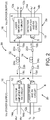
- FIG. 2 is a diagram identifying some features of a bidirectional full-duplex data transmission system 30 comprising one pair of dual-fiber bidirectional transceivers 2a and 2b that each transmit and receive light of the same wavelength, each of the single-wavelength dual-fiber bidirectional transceivers 2a and 2b having the same components as the components of the single-wavelength dual-fiber bidirectional transceiver 2 depicted in FIG. 1 .
- the laser 4 of the single-wavelength dual-fiber bidirectional transceiver 2a is optically coupled to emit light toward the photodetector 8 of the single-wavelength dual-fiber bidirectional transceiver 2b via an optical cable 32 comprising a glass optical fiber 18a, a connector 22a, a gigabit plastic optical fiber 24a, a connector 22b and a glass optical fiber 18c connected in series.
- the laser 4 of the single-wavelength dual-fiber bidirectional transceiver 2b is optically coupled to emit light toward to the photodetector 8 of the single-wavelength dual-fiber bidirectional transceiver 2a via an optical cable 34 comprising a glass optical fiber 18d, a connector 22c, a gigabit plastic optical fiber 24b, a connector 22d and a glass optical fiber 18b connected in series.
- Both single-wavelength dual-fiber bidirectional transceivers 2a and 2b transmit and receive light having a wavelength ⁇ 1 .
- the optical cables 32 and 34 may be identical in construction.
- the inclusion of gigabit plastic optical fibers 24a and 24b enables bidirectional full-duplex data transmission between single-wavelength dual-fiber bidirectional transceivers 2a and 2b at a high data rate (>1 Gbits/sec).
- FIG. 3 is a diagram identifying components of a known bidirectional full-duplex data transmission system 40 having eight full-duplex glass fiber optical cables 42a-42h optically coupling the transceivers of one set of line replaceable units 44 (hereinafter "LRU set 44") to the transceivers of another set of line replaceable units 46 (hereinafter "LRU set 46").
- LRU set 44 may be disposed in a forward section of an airplane while LRU set 46 is disposed in an aft section of the airplane.
- the LRU set 44 comprises four LRUs (respectively designated LRU#1, LRU#3, LRU#5 and LRU#7), whereas the LRU set 46 comprises four LRUs (respectively designated LRU#2, LRU#4, LRU#6 and LRU#8).
- Each of the eight LRUs incorporates a respective dual-fiber transceiver (respectively designated Trx#1 through Trx#8).
- the LRU set 44 comprises four dual-fiber transceivers (respectively designated Trx#1, Trx#3, Trx#5 and Trx#7), whereas the LRU set 46 comprises four dual-fiber transceivers (respectively designated Trx#2, Trx#4, Trx#6 and Trx#8).
- the transceiver Trx#1 is optically coupled to the transceiver Trx#2 via glass optical fiber cables 42a and 42b to enable full-duplex communication between transceivers Trx#1 and Trx#2.
- Transceivers Trx#1 and Trx#2 are configured so that they transmit and receive light having a wavelength ⁇ 1 .
- the transceiver Trx#3 is optically coupled to the transceiver Trx#4 via glass optical fiber cables 42c and 42d to enable full-duplex communication between transceivers Trx#3 and Trx#4.
- Transceivers Trx#3 and Trx#4 are configured so that they transmit and receive light having a wavelength ⁇ 2 .
- the transceiver Trx#5 is optically coupled to the transceiver Trx#6 via glass optical fiber cables 42e and 42f to enable full-duplex communication between transceivers Trx#5 and Trx#6.
- Transceivers Trx#5 and Trx#6 are configured so that they transmit and receive light having a wavelength ⁇ 3 .
- the transceiver Trx#7 is optically coupled to the transceiver Trx#8 via glass optical fiber cables 42g and 42h to enable full-duplex communication between transceivers Trx#7 and Trx#8.
- Transceivers Trx#7 and Trx#8 are configured so that they transmit and receive light having a wavelength ⁇ 4 .
- Each of the dual-fiber transceivers is of the type depicted in FIG. 1 . In the system shown in FIG. 3 , wavelengths ⁇ 1 to ⁇ 4 can be different or equal to each other.
- the bidirectional full-duplex data transmission system 40 depicted in FIG. 3 has eight full-duplex glass optical fiber cables 42a-42h cables to be routed inside the airplane's cable plant.
- the technological improvement that is the subject of this disclosure provides the design for a fiber optical network which comprises a single gigabit plastic optical fiber cable for optical coupling one set of four bidirectional transceivers to another set of four bidirectional transceivers, thereby reducing the number of cables from eight to one single fiber optical cable running a length of the airplane from a front section to an aft section.
- FIG. 4 is a diagram identifying some features of a single-fiber full-duplex bidirectional transceiver design in which the dual-wavelength single-fiber bidirectional transceiver 20 transmits light having a first wavelength ⁇ 1 and receives light having a second wavelength ⁇ 2 different than the first wavelength ⁇ 1 via the same glass optical fiber 18.
- the dual-wavelength single-fiber bidirectional transceiver 20 comprises a laser 4 and a photodetector 8.
- the laser 4 is driven to emit light of a wavelength ⁇ 1 by a laser driver and transmit circuit 6 in response to receipt of differential transmit signals Tx + and Tx- from an associated line replaceable unit (not shown) via transmit electrical signal lines 12a and 12b respectively.
- the dual-wavelength single-fiber bidirectional transceiver 20 depicted in FIG. 4 is capable of single-fiber operation because it is equipped in its optical front end with a wavelength-division multiplexing (WDM) filter 36 (hereinafter “WDM filter 36") which passes the optical signal from the laser 4 at one wavelength ⁇ 1 and reflects the received optical signal at a different wavelength ⁇ 2 toward the photodetector 8.
- WDM filter 36 wavelength-division multiplexing
- the WDM filter 36 inside of the dual-wavelength single-fiber bidirectional transceiver 20 is a wavelength-selective bandpass filter designed in accordance with a high cross-talk isolation technique. Use of such isolation ensures that the optical signal from the local laser 4 is not detected by the receiver in the same bidirectional transceiver.
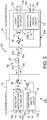
- FIG. 5 is a diagram identifying some features of a bidirectional full-duplex data transmission system 50 comprising one pair of dual-wavelength single-fiber bidirectional transceivers 20a and 20b, each dual-wavelength single-fiber bidirectional transceiver 20a and 20b being of the type depicted in FIG. 4 .
- the laser 4 of the dual-wavelength single-fiber bidirectional transceiver 20a is optically coupled to emit light toward the photodetector 8 of the dual-wavelength single-fiber bidirectional transceiver 20b via an optical cable 52 comprising a glass optical fiber 18a, a connector 22a, a gigabit plastic optical fiber 24, a connector 22b and a glass optical fiber 18b connected in series.
- the laser 4 of the dual-wavelength single-fiber bidirectional transceiver 20b is optically coupled to emit light toward to the photodetector 8 of the dual-wavelength single-fiber bidirectional transceiver 20a via the same optical cable 52.
- the dual-wavelength single-fiber bidirectional transceiver 20a transmits light having a wavelength ⁇ 1 and receives light having a wavelength receives ⁇ 2 .
- the dual-wavelength single-fiber bidirectional transceiver 20b transmits light having a wavelength ⁇ 2 and receives light having a wavelength receives ⁇ 1 .
- Each of the dual-wavelength single-fiber bidirectional transceivers 20a and 20b comprises a WMD optical filter 36 that passes light having a wavelength ⁇ 1 and reflects light having a wavelength ⁇ 2 .
- the bidirectional full-duplex data transmission system 50 depicted in FIG. 5 is capable of transmitting data at a rate greater than 1 Gbits/sec in either direction due to the presence of gigabit plastic optical fiber 24 in the optical cable 52.
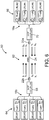
- FIG. 6 is a diagram identifying components of a bidirectional full-duplex data transmission system 60 having one full-duplex optical cable 62 for optically coupling four dual-wavelength single-fiber bidirectional transceivers Trx#1, Trx#3, Trx#5 and Trx#7 of one LRU set 64 of line replaceable units LRU#1, LRU#3, LRU#5 and LRU#7 to four dual-wavelength single-fiber bidirectional transceivers Trx#2, Trx#4, Trx#6 and Trx#8 of another LRU set 66 of line replaceable units LRU#2, LRU#4, LRU#6 and LRU#8.
- the eight dual-wavelength single-fiber bidirectional transceivers Trx#1-Trx#8 transmit light having different wavelengths ⁇ 1 to ⁇ 8 .
- the bidirectional full-duplex data transmission system 60 comprises a first set of four glass optical fibers 18a, a first glass optical fiber coupler 70 connected to the first set of four glass optical fibers 18a, a second set of four glass optical fibers 18b and a second glass optical fiber coupler 68 connected to the second set of four glass optical fibers 18a.
- the four glass optical fibers 18b optically couple the glass optical fiber coupler 70 to the dual-wavelength single-fiber bidirectional transceivers Trx#2, Trx#4, Trx#6 and Trx#8, while the four glass optical fibers 18b optically couple the glass optical fiber coupler 68 to the dual-wavelength single-fiber bidirectional transceivers Trx#1, Trx#3, Trx#5 and Trx#7.
- the bidirectional full-duplex data transmission system 60 further comprises a gigabit plastic optical fiber 24 having one end connected to glass optical fiber coupler 70 by a connector 22a and another end connected to glass optical fiber coupler 68 by a connector 22b.
- the laser 4 of the dual-wavelength single-fiber bidirectional transceiver Trx#1 is optically coupled to emit light having a wavelength ⁇ 1 toward the photodetector 8 of the dual-wavelength single-fiber bidirectional transceiver Trx#2, while the laser 4 of the dual-wavelength single-fiber bidirectional transceiver Trx#2 is optically coupled to emit light having a wavelength ⁇ 2 toward the photodetector 8 of the dual-wavelength single-fiber bidirectional transceiver Trx#1.
- Each pair of optically coupled dual-wavelength single-fiber bidirectional transceivers Trx#1 through Trx#8 seen in FIG. 6 comprises a respective WMD optical filter (not shown in FIG. 6 ) of the type depicted in FIG. 4 , except that the WMD optical filters for the respective pairs of transceivers are configured differently for each pair.
- the WMD optical filters inside dual-wavelength single-fiber bidirectional transceivers Trx#1 and Trx#2 are designed to pass light of wavelength ⁇ 1 and reflect light of wavelength ⁇ 2
- the WMD optical filters inside dual-wavelength single-fiber bidirectional transceivers Trx#3 and Trx#4 are designed to pass light of wavelength ⁇ 3 and reflect light of wavelength ⁇ 4 , and so forth.
- the bidirectional full-duplex data transmission system 60 depicted in FIG. 6 is capable of transmitting data at a rate greater than 1 Gbits/sec in either direction due to the presence of gigabit plastic optical fiber 24 in the optical cable 62.
- the wavelengths ⁇ 1 to ⁇ 8 are selected to minimize attenuation in the gigabit plastic optical fiber 24.
- the attenuation of the optical signal as it passes through the optical fiber will vary as a function of the wavelength of the optical signal.
- each optical fiber material has a characteristic function representing the attenuation versus wavelength.
- one plastic optical fiber material that has proven to be suitable for Gigabit Ethernet (GbE) data transmission is perfluorinated polymer having a graded index of refraction and having a high data transmission rate over a wide wavelength range.
- the gigabit plastic optical fiber 24 may be Fontex® plastic optical fiber commercially available from Asahi Glass Co., Ltd., Tokyo, Japan. FIG.
- the attenuation is lowest in the range of 750 nm to 1350 nm.
- Other suitable gigabit plastic optical fiber materials having a range of wavelengths where attenuation is acceptable can be utilized.
- the wavelengths ⁇ 1 through ⁇ 8 are selected from the range of wavelengths where attenuation is relatively low compared to the attenuation at other wavelengths.
- the laser 4 in the transmitters of the bidirectional transceivers can be implemented with single-mode distributed feedback lasers, multi-mode Fabry-Perot lasers or vertical cavity surface-emitting lasers for high optical output power and low modal noise.
- the photodetector 8 in the receivers of the bidirectional transceivers can be implemented with a high-responsivity p-type intrinsic n-type (PIN) photodiode or an avalanche photodiode to provide high receiver sensitivity.
- PIN p-type intrinsic n-type
- each of the glass optical fiber couplers 68 and 70 shown in FIG. 6 comprises a 4x1 mode-independent multi-mode optical coupler (formed by heat fusing glass) that optically couples a respective set of four bidirectional transceivers to the opposing ends of the gigabit plastic optical fiber 24.
- the advantages of a mode-independent optical coupler are: (1) it has an optical output splitting ratio independent of the input optical mode from the transmitter's laser source; and (2) the mode-independent optical coupler has optical reflection lower than -40 dB to reduce the optical signal reflected from the adjacent bidirectional transceiver.
- Respective ultra-low-reflection connectors 18a and 18b are used to connect the outputs of the glass optical fiber couplers 68 and 70 to the opposing ends of the gigabit plastic optical fiber 24.
- the end face of the glass optical fiber on one side of the glass optical fiber couplers and the confronting end face of the gigabit plastic optical fiber 24 are angles and polished.
- the ultra-low-reflection connectors 18a and 18b are formed with a small angle at those end faces.
- FIG. 6 does not seek to depict any particular configuration or type of optical fiber connector.
- Each of the connectors 22a and 22b may have a generally circular cylindrical structure.
- some connectors include springs and associated structure for pushing the ends of two fiber optic devices into contact with each other. Such springs and associated structure are also not shown in FIG. 6 .
- the connector's optical coupling loss depends on the quality of the confronting (e.g., abutting) end faces of each glass optical fiber coupler 68 or 70 and gigabit plastic optical fiber 24.
- a poor end face can introduce an additional optical loss per connector.
- the provision of smooth optical fiber end faces is important to reduce the connector's optical coupling loss for avionics networks where the optical cable's power budget is very tight due to relatively long optical cable lengths.
- FIG. 6 comprises a forward set of four line replaceable units optically communicating with an aft set of four line replaceable units on an airplane
- the concepts disclosed herein may be applied in situations where the number of line replaceable units in each of the forward and aft sets is different than four, for example, as few as two and perhaps as many as sixteen if the resulting optical losses are acceptable.
- the system described above may in the alternative be implemented using all glass optical fiber.
- GbPOF is a special application (or solution) where glass fiber is a problem for airplane installation. But for many long-distance terrestrial, data center and fiber-to-the-home/office applications (non-aerospace), glass optical fiber installation is not a major problem.
- the minimum loss region lies in a range of wavelengths from 1350 nm to 1600 nm.
- Example wavelength pairs for glass optical fiber implementation are: 1365 and 1460 nm; 1465 and 1550 nm; 1530 and 1560 nm; 1565 and 1600 nm, and many other possible selections.
- GbGOF and GbPOF have different optical loss characteristics which vary with wavelength as shown in FIGS. 7 and 8 .
- an avionics system may comprise multiple bidirectional transceivers configured to transmit and receive proper wavelengths that correspond to the optical loss minimum for the particular gigabit plastic or glass optical fiber being employed.
- the design disclosed herein enables the use of long gigabit plastic optical fiber links (100 meters or longer) in medium- and large-sized airplanes.
- the configuration disclosed herein reduces the fiber count in the airplane by a factor of eight for the specific example wherein one set of four bidirectional transceivers respectively communicates with four bidirectional transceivers in a corresponding set.
- the fiber count reduction factor will be a function of how many bidirectional transceivers are optically coupled in pairs by a single gigabit plastic or glass optical fiber. The reduced fiber count reduces weight, size and installation cost of fiber cables in the airplane.
- the resulting data transmission system is capable of full-duplex or half-duplex communication between LRUs with a single fiber link.
Description
- The technology disclosed herein generally relates to fiber optical networks that enable communication between electrical components.
- An optical fiber is a cylindrical dielectric waveguide that transmits light along its axis. The fiber consists of a transparent core surrounded by a transparent cladding layer (hereinafter "cladding"), both of which are made of dielectric materials. Light is kept in the core by the phenomenon of total internal reflection. To confine the optical signal in the core, the refractive index of the core is greater than that of the cladding. The boundary between the core and cladding may either be abrupt, as in step-index fiber, or gradual, as in graded-index fiber. Optical fibers can be made of glass or plastic.
- Optical networking using plastic optical fiber (POF) has advantages over copper wiring in weight, size, bandwidth, power, and electromagnetic immunity. POF has advantages over glass optical fiber (GOF) in ease of handling, installation and maintenance. POF core material can range from acrylate to perfluorinated polymer. POF index profile can range from step index to graded index. POF geometry can range from single core to multi-core. POF core can accommodate single mode (a single optical path in a very small fiber core) to multi-mode (multiple optical paths in a larger fiber core). Using POF may result in appreciable weight savings. The weight savings may be significant for networks onboard vehicles, such as airplanes, where the weight savings may result in reduced fuel consumption and lower emissions.
- It is common practice to connect a number of line replaceable units (LRUs) to each other to achieve communication within an avionics system. For example, a number of LRUs in the forward section of a vehicle (e.g., an airplane) have been connected to a number of LRUs in the aft section of the vehicle. Connecting each LRU to every other LRU could result in an unreasonably large number of connections. Additionally, many of the connections between LRUs may be long, resulting in optical losses.
- Fiber optic networks have the advantages of higher speed, lower weight and electromagnetic interference immunity over copper networks. Many models of commercial airplanes have fiber optic networks for size, weight and power reduction. In some cases the large number of glass optical fiber (GOF) cables in the airplane is an important factor contributing to high manufacturing cost. To reduce the cost for installing fiber optic network in airplane, there is a need to reduce the number of fiber optic cables used in the airplanes.
- A typical solution to reduce fiber count is to use a wavelength division multiplexing (WDM) system. However, typical WDM systems are not compatible with multimode optical fiber currently used onboard commercial transport aircraft. Typical WDM components are designed for use with single-mode fiber. Single-mode fiber has a diameter smaller than 10 microns and therefore is very sensitive to dust, contamination, and misalignment from airplane vibration and shock. WDM components such as multiplexing and demultiplexing array waveguide gratings (AWG) are expensive and not proven for use in harsh avionic environments.
-
US2014270778 A1 describes an optical transceiver module which includes N light sources, N light detectors, a bidirectional fiber port, and an optical network having 2N-1 wavelength-selective elements. The number 2N represents the total number of transmit and receive channels in a bidirectional system in which transmit and receive signals corresponding to the transmit and receive channels. Each light source corresponds to one transmit channel and emits an optical transmit signal having a unique transmit wavelength. Each light detector corresponds to one receive channel and detects an optical receive signal having a unique receive wavelength. The optical network couples each light source to the bidirectional fiber port via a corresponding transmit path through the optical network. The optical network further couples each light detector to the bidirectional fiber port via a corresponding receive path through the optical network. Each transmit and receive path includes some of the wavelength-selective elements. -
WO2009035202 A1 describes a multiple passive optical network system and a wavelength splitter/combiner used in the same. The multiple passive optical network (PON) system includes a first PON, and a second PON which provides a service different in speed and capacity from the first PON while partially sharing network resources with the first PON. Thereby a subscriber can receive service through a network having a desired capacity and speed. -
EP2091166 A1 describes a passive optical network communication system which includes a number of subscribers' units connected to a central line termination unit through a passive optical coupler. The line termination unit includes a first section that transmits and receives a code division multiplex (CDM) signal, a second section that transmits and receives a time division multiplex (TDM) signal, and a wavelength multiplexing filter that combines the transmitted CDM and TDM signals into a single downstream optical signal, and separates the CDM and TDM components of an upstream signal received from the subscribers' units through the passive optical coupler. The CDM signal provides channels for digital video transmission to CDM-capable subscribers' units. - The subject matter disclosed in some detail below is directed to a bidirectional, multi-wavelength fiber optical network that enables communication between electrical components (such as line replaceable units) at high data transmission rates (e.g., greater than 1 Gbits/sec). The proposed fiber optical network in accordance with some embodiments comprises a single optical fiber (plastic or glass) capable of transmitting data at rates faster than 1 Gbits/sec. Such a plastic optical fiber will be referred to herein as a "gigabit plastic optical fiber" (GbPOF). Gigabit plastic optical fiber is made of ductile perfluorinated polymer and it does not break during tight cable bending. One example GbPOF has a 55-micron core diameter and a 500-micron cladding diameter. The above-mentioned glass optical fiber will be referred to herein as a "gigabit glass optical fiber" (GbGOF). One example of a GbGOF is the OM4 multimode glass optical fiber with a 50-micron core diameter and a 125-micron cladding diameter. This GbGOF has bandwidth for 10 Gbits/sec over distances up to 400 meters.
- In contrast to a pure silica GOF core, a multi-mode GbPOF with the same core diameter is more imperfect with long random polymer chains in spaghetti shapes. These polymer chains create strong forward mode coupling and result in less reflected light that can interfere with the laser source. The strong mode coupling in a POF core also reduces the coherency of the laser source and results in minimal modal interference along the fiber length. The optical network proposed herein solves the problems of existing WDM systems.
- In accordance with one embodiment, the proposed optical network comprises of the following elements and characteristics: (1) the laser source can be a single-mode distributed feedback laser, a multi-mode Fabry-Perot laser, or a vertical cavity surface-emitting laser; (2) multiple wavelengths flowing bidirectionally and simultaneously with each wavelength serve a separate communication function, e.g., control data, sensing data, health status data, configuration data, etc.; (3) a single-fiber multi-mode GbPOF or GbGOF link; (4) high-directional and mode-independent GOF couplers between multiple laser sources and the single-fiber GbPOF or GbGOF link; (5) angle/polished connectors between the GOF couplers and the GbPOF or GbGOF link; and (6) angle/polished connectors are not required for connecting segments along the GbPOF or GbGOF link, i.e., flat polish is sufficient. In accordance with some embodiments, the number of fiber cables extending from the forward section to the aft section of the airplane can be reduced by a factor of eight or more by substituting one GbPOF or GbGOF for eight or more POF or GOF.
- In accordance with one embodiment, the optical network proposed herein reduces multiple fiber optic links to a single GbPOF or GbGOF link for full-duplex or half-duplex bidirectional data communication between multiple LRUs onboard the airplane.
- In accordance with a preferred embodiment, the optical network uses low-cost, high-performance small form factor pluggable (SFP) bidirectional optical transceivers at the wavelength ranges where the optical losses of the GbPOF are very low if not minimal. In addition, the optical network proposed herein uses GOF couplers having low optical reflection to reduce the optical signal reflected from the adjacent bidirectional transceiver. Ultra-low-reflection (or high optical return loss) connectors are used to connect the GbPOF to the outputs of the GOF couplers.
- Although various embodiments of a bidirectional fiber optical network that transmits and receives light of multiple wavelengths by way of a single gigabit plastic or gigabit glass optical fiber for use in the avionics system of an airplane will be described in some detail below, one or more of those embodiments may be characterized by one or more of the following aspects.
- One aspect of the subject matter disclosed in detail below is a data transmission system comprising: an optical cable comprising a gigabit optical fiber; and first through fourth transceivers each comprising an optical filter, a laser disposed to transmit light through the optical filter, and a photodetector disposed to receive light reflected by the optical filter, wherein: the laser and photodetector of the first transceiver are respectively optically coupled to the photodetector and laser of the second transceiver, and the laser and photodetector of the third transceiver are respectively optically coupled to the photodetector and laser of the fourth transceiver by way of the gigabit optical fiber; the laser of the first transceiver emits light having a first wavelength, the laser of the second transceiver emits light having a second wavelength, the laser of the third transceiver emits light having a third wavelength, and the laser of the fourth transceiver emits light having a fourth wavelength; and the optical filter of the first and second transceivers passes light having the first wavelength and reflects light having the second wavelength, and the optical filter of the third and fourth transceivers passes light having the third wavelength and reflects light having the fourth wavelength. The data transmission system described in the preceding paragraph may further comprise: fifth through eighth transceivers each comprising an optical filter, a laser disposed to transmit light through the optical filter, and a photodetector disposed to receive light reflected by the optical filter, wherein: the laser and photodetector of the fifth transceiver are respectively optically coupled to the photodetector and laser of the sixth transceiver, and the laser and photodetector of the seventh transceiver are respectively optically coupled to the photodetector and laser of the eighth transceiver by way of the gigabit optical fiber; the laser of the fifth transceiver emits light having a fifth wavelength, the laser of the sixth transceiver emits light having a sixth wavelength, the laser of the seventh transceiver emits light having a seventh wavelength, and the laser of the eighth transceiver emits light having an eighth wavelength; and the optical filter of the fifth and sixth transceivers passes light having the fifth wavelength and reflects light having the sixth wavelength, and the optical filter of the seventh and eighth transceivers passes light having the seventh wavelength and reflects light having the eighth wavelength. This data transmission system further comprises: a first glass optical fiber coupler that optically couples the laser and photodetector of each of the first, third, fifth and seventh transceivers to one end of the gigabit optical fiber; and a second glass optical fiber coupler that optically couples the laser and photodetector of each of the second, fourth, sixth and eighth transceivers to another end of the gigabit optical fiber.
- In accordance with various embodiments, the first through eighth wavelengths are in a wavelength range from 750 to 1600 nm. In accordance with one proposed implementation, the first wavelength is 1270 nm, the second wavelength is 1330 nm, the third wavelength is 850 nm, the fourth wavelength is 880 nm, the fifth wavelength is 780 nm, the sixth wavelength is 980 nm, the seventh wavelength is 1200 nm and the eighth wavelength is 1230 nm. In accordance with one embodiment of the system described in the preceding paragraphs, each optical filter of the first through eighth transceivers is a wavelength-selective bandpass filter, and each of the first through eighth transceivers is a dual-wavelength single-fiber bidirectional transceiver.
- Another aspect of the subject matter disclosed in detail below is a method for enabling bidirectional full-duplex data transmission between first and second sets of line replaceable units, comprising: (a) equipping each line replaceable unit with a dual-wavelength single-fiber bidirectional transceiver; (b) optically coupling single fibers of the dual-wavelength single-fiber bidirectional transceivers of the first set of line replaceable units to one end of an optical cable that comprises a gigabit optical fiber; and (c) optically coupling single fibers of the dual-wavelength single-fiber bidirectional transceivers of the second set of line replaceable units to another end of the optical cable, wherein the first set of line replaceable units includes at least two line replaceable units, and the number of line replaceable units in the second set is the same as the number of line replaceable units in the first set.
- In accordance with one embodiment of the foregoing method, the single fibers are made of glass and step (b) comprises: coupling the single fibers of the dual-wavelength single-fiber bidirectional transceivers of the first set of line replaceable units into a first glass optical fiber; and connecting one end of the first glass optical fiber to one end of the gigabit optical fiber. In addition, the first set of line replaceable units comprises a first line replaceable unit, the second set of line replaceable units comprises a second line replaceable unit, and step (a) comprises: equipping the first line replaceable unit with a first dual-wavelength single-fiber bidirectional transceiver that emits light having a first wavelength and detects light having a second wavelength; and equipping the second line replaceable unit with a second dual-wavelength single-fiber bidirectional transceiver that emits light having the second wavelength and detects light having the first wavelength.
- A further aspect of the subject matter disclosed in detail below is a data communications system, comprising: first and second pluralities of electrical devices configured for sending and receiving electrical signals representing data; a first plurality of dual-wavelength single-fiber bidirectional transceivers, each dual-wavelength single-fiber bidirectional transceiver of the first plurality comprising a respective transmit circuit that converts electrical signals received from a respective one of the first plurality of electrical devices into optical signals and a respective receive circuit that converts optical signals into electrical signals to be sent to the respective one of the first plurality of electrical devices; a second plurality of dual-wavelength single-fiber bidirectional transceiver, each dual-wavelength single-fiber bidirectional transceiver of the second plurality comprising a respective transmit circuit that converts electrical signals received from a respective one of the second plurality of electrical devices into optical signals and a respective receive circuit that converts optical signals into electrical signals to be sent to the respective one of the second plurality of electrical devices; a first glass optical fiber coupler optically coupled to a single fiber of each of the first plurality of dual-wavelength single-fiber bidirectional transceivers; a second glass optical fiber coupler optically coupled to a single fiber of each of the second plurality of dual-wavelength single-fiber bidirectional transceivers; and an optical cable connecting the first glass optical fiber coupler to the second glass optical fiber coupler, wherein the optical cable comprises a gigabit optical fiber.
- In accordance with one embodiment of the data communications system described in the preceding paragraph, the first plurality of electronic devices are line replaceable units located in a forward section of an airplane and the second plurality of electronic devices are line replaceable units located in an aft section of the airplane.
- In accordance with one proposed implementation of the data communications system: a first dual-wavelength single-fiber bidirectional transceiver of the first plurality emits light having a first wavelength and detects light having a second wavelength; a second dual-wavelength single-fiber bidirectional transceiver of the second plurality emits light having the second wavelength and detects light having the first wavelength; a third dual-wavelength single-fiber bidirectional transceiver of the first plurality emits light having a third wavelength and detects light having a fourth wavelength; a fourth dual-wavelength single-fiber bidirectional transceiver of the second plurality emits light having the fourth wavelength and detects light having the third wavelength; a fifth dual-wavelength single-fiber bidirectional transceiver of the first plurality emits light having a fifth wavelength and detects light having a sixth wavelength; a sixth dual-wavelength single-fiber bidirectional transceiver of the second plurality emits light having the sixth wavelength and detects light having the fifth wavelength; a seventh dual-wavelength single-fiber bidirectional transceiver of the first plurality emits light having a seventh wavelength and detects light having an eighth wavelength; and an eighth dual-wavelength single-fiber bidirectional transceiver of the second plurality emits light having the eighth wavelength and detects light having the seventh wavelength, wherein the first through eighth wavelengths are different. In one example, the first wavelength is 1270 nm, the second wavelength is 1330 nm, the third wavelength is 850 nm, the fourth wavelength is 880 nm, the fifth wavelength is 780 nm, the sixth wavelength is 980 nm, the seventh wavelength is 1200 nm and the eighth wavelength is 1230 nm.
- Other aspects of fiber optical networks for enabling optical communication at high data transmission rates are disclosed below.
- The features, functions and advantages discussed in the preceding section can be achieved independently in various embodiments or may be combined in yet other embodiments. Various embodiments will be hereinafter described with reference to drawings for the purpose of illustrating the above-described and other aspects. None of the diagrams briefly described in this section are drawn to scale.
-
FIG. 1 is a diagram identifying some features of a dual-fiber bidirectional transceiver design in which the transceiver transmits and receives light of the same wavelength. -
FIG. 2 is a diagram identifying some features of a bidirectional full-duplex data transmission system comprising one pair of dual-fiber bidirectional transceivers that each transmit and receive light of the same wavelength, each single-wavelength dual-fiber bidirectional transceiver being of the type depicted inFIG. 1 . -
FIG. 3 is a diagram identifying components of a known bidirectional full-duplex data transmission system having eight full-duplex glass fiber optical cables optically coupling the single-wavelength dual-fiber bidirectional transceivers of one set of line replaceable units to the single-wavelength dual-fiber bidirectional transceivers of another set of line replaceable units. -
FIG. 4 is a diagram identifying some features of a single-fiber bidirectional transceiver design in which the transceiver transmits light having a first wavelength and receives light having a second wavelength different than the first wavelength. -
FIG. 5 is a diagram identifying some features of a bidirectional full-duplex data transmission system comprising one pair of dual-wavelength single-fiber bidirectional transceivers, each dual-wavelength single-fiber bidirectional transceivers being of the type depicted inFIG. 4 . -
FIG. 6 is a diagram identifying components of a bidirectional full-duplex data transmission system having one full-duplex optical cable connecting the dual-wavelength single-fiber bidirectional transceivers of one set of line replaceable units to the dual-wavelength single-fiber bidirectional transceivers of another set of line replaceable units, each dual-wavelength single-fiber bidirectional transceiver transmitting light at a different wavelength. -
FIG. 7 is a graph showing the attenuation spectrum for a known gigabit plastic optical fiber material. -
FIG. 8 is a graph showing the attenuation spectrum for a known gigabit glass optical fiber material. - Reference will hereinafter be made to the drawings in which similar elements in different drawings bear the same reference numerals.
- Illustrative embodiments of optical networks are described in some detail below. However, not all features of an actual implementation are described in this specification. A person skilled in the art will appreciate that in the development of any such actual embodiment, numerous implementation-specific decisions must be made to achieve the developer's specific goals, such as compliance with system-related and business-related constraints, which will vary from one implementation to another. Moreover, it will be appreciated that such a development effort might be complex and time-consuming, but would nevertheless be a routine undertaking for those of ordinary skill in the art having the benefit of this disclosure.
- Various embodiments of a fiber optical network for enabling optical communication between line replaceable units on an airplane at high data transmission rates (e.g., greater than 1 Gbits/sec) will be described in detail below for the purpose of illustration. However, implementation of the fiber optical networks disclosed herein is not limited solely to the environment of an airplane, but rather may be utilized in fiber optical networks onboard other types of vehicles or other types of fiber optical networks (e.g., long-distance terrestrial, data center and fiber-to-the-home/office applications). In addition, although the particular example embodiment disclosed in some detail hereinafter employs a GbPOF, alternative embodiments may employ GbGOF.
-
FIG. 1 is a diagram identifying some features of a dual-fiber bidirectional transceiver design in which the transceiver transmits and receives light of the same wavelength. [As used herein, the term "wavelength" in the context of coherent laser light means the center wavelength of laser light having a narrow bandwidth.] In this example, the transceiver is a single-wavelength dual-fiber bidirectional transceiver 2 comprising alaser 4 and aphotodetector 8. Thelaser 4 is driven to emit light of a wavelength λ 1 by a laser driver and transmitcircuit 6 in response to receipt of differential transmit signals Tx+ and Tx- from an associated line replaceable unit (not shown) via transmitelectrical signal lines circuit 6 comprises electrical circuitry that converts those electrical differential signals to electrical digital signals representing the data to be transmitted by thelaser 4. Conversely, thephotodetector 8 receives light of wavelength λ 1 and converts that detected light into electrical digital signals which are provided to a detector amplifier and receivecircuit 10. The detector amplifier and receivecircuit 10 in turn comprises electrical circuitry that converts those electrical digital signals to electrical differential receive signals Rx+ and Rx- representing the data received. The electrical differential receive signals Rx+ and Rx- are transmitted to other circuitry in the line replaceable unit via receiveelectrical signal lines fiber bidirectional transceiver 2 receives electrical power having a voltage Vcc via transceiverpower supply line 16. - The
laser 4 is optically coupled to a glassoptical fiber 18a, while thephotodetector 8 is optically coupled to a glassoptical fiber 18b. Both glassoptical fibers -
FIG. 2 is a diagram identifying some features of a bidirectional full-duplexdata transmission system 30 comprising one pair of dual-fiberbidirectional transceivers bidirectional transceivers fiber bidirectional transceiver 2 depicted inFIG. 1 . In this example, thelaser 4 of the single-wavelength dual-fiber bidirectional transceiver 2a is optically coupled to emit light toward thephotodetector 8 of the single-wavelength dual-fiber bidirectional transceiver 2b via anoptical cable 32 comprising a glassoptical fiber 18a, aconnector 22a, a gigabit plasticoptical fiber 24a, aconnector 22b and a glassoptical fiber 18c connected in series. Similarly, thelaser 4 of the single-wavelength dual-fiber bidirectional transceiver 2b is optically coupled to emit light toward to thephotodetector 8 of the single-wavelength dual-fiber bidirectional transceiver 2a via anoptical cable 34 comprising a glassoptical fiber 18d, aconnector 22c, a gigabit plasticoptical fiber 24b, aconnector 22d and a glassoptical fiber 18b connected in series. Both single-wavelength dual-fiberbidirectional transceivers optical cables optical fibers bidirectional transceivers -
FIG. 3 is a diagram identifying components of a known bidirectional full-duplexdata transmission system 40 having eight full-duplex glass fiberoptical cables 42a-42h optically coupling the transceivers of one set of line replaceable units 44 (hereinafter "LRU set 44") to the transceivers of another set of line replaceable units 46 (hereinafter "LRU set 46"). For example, LRU set 44 may be disposed in a forward section of an airplane while LRU set 46 is disposed in an aft section of the airplane. In this example, the LRU set 44 comprises four LRUs (respectively designatedLRU# 1,LRU# 3,LRU# 5 and LRU#7), whereas the LRU set 46 comprises four LRUs (respectively designatedLRU# 2,LRU# 4,LRU# 6 and LRU#8). Each of the eight LRUs incorporates a respective dual-fiber transceiver (respectively designatedTrx# 1 through Trx#8). - In this example, the LRU set 44 comprises four dual-fiber transceivers (respectively designated
Trx# 1,Trx# 3,Trx# 5 and Trx#7), whereas the LRU set 46 comprises four dual-fiber transceivers (respectively designatedTrx# 2,Trx# 4,Trx# 6 and Trx#8). Thetransceiver Trx# 1 is optically coupled to thetransceiver Trx# 2 via glassoptical fiber cables transceivers Trx# 1 andTrx# 2.Transceivers Trx# 1 andTrx# 2 are configured so that they transmit and receive light having a wavelength λ 1. Thetransceiver Trx# 3 is optically coupled to thetransceiver Trx# 4 via glassoptical fiber cables transceivers Trx# 3 andTrx# 4.Transceivers Trx# 3 andTrx# 4 are configured so that they transmit and receive light having a wavelength λ 2. Thetransceiver Trx# 5 is optically coupled to thetransceiver Trx# 6 via glassoptical fiber cables transceivers Trx# 5 andTrx# 6.Transceivers Trx# 5 andTrx# 6 are configured so that they transmit and receive light having a wavelength λ 3. Thetransceiver Trx# 7 is optically coupled to thetransceiver Trx# 8 via glassoptical fiber cables transceivers Trx# 7 andTrx# 8.Transceivers Trx# 7 andTrx# 8 are configured so that they transmit and receive light having a wavelength λ 4. Each of the dual-fiber transceivers is of the type depicted inFIG. 1 . In the system shown inFIG. 3 , wavelengths λ1 to λ4 can be different or equal to each other. - The bidirectional full-duplex
data transmission system 40 depicted inFIG. 3 has eight full-duplex glassoptical fiber cables 42a-42h cables to be routed inside the airplane's cable plant. To reduce the cost and labor related to this large number of glass optical fiber cables in the airplane, the technological improvement that is the subject of this disclosure provides the design for a fiber optical network which comprises a single gigabit plastic optical fiber cable for optical coupling one set of four bidirectional transceivers to another set of four bidirectional transceivers, thereby reducing the number of cables from eight to one single fiber optical cable running a length of the airplane from a front section to an aft section. -
FIG. 4 is a diagram identifying some features of a single-fiber full-duplex bidirectional transceiver design in which the dual-wavelength single-fiber bidirectional transceiver 20 transmits light having a first wavelength λ 1 and receives light having a second wavelength λ 2 different than the first wavelength λ 1 via the same glassoptical fiber 18. The dual-wavelength single-fiber bidirectional transceiver 20 comprises alaser 4 and aphotodetector 8. Thelaser 4 is driven to emit light of a wavelength λ 1 by a laser driver and transmitcircuit 6 in response to receipt of differential transmit signals Tx+ and Tx- from an associated line replaceable unit (not shown) via transmitelectrical signal lines circuit 6 comprises electrical circuitry that converts those electrical differential signals to electrical digital signals representing the data to be transmitted by thelaser 4. Conversely, thephotodetector 8 receives light of wavelength λ 2 and converts that detected light into electrical digital signals which are provided to a detector amplifier and receivecircuit 10. The detector amplifier and receivecircuit 10 in turn comprises electrical circuitry that converts those electrical digital signals to electrical differential receive signals Rx+ and Rx- representing the data received. The electrical differential receive signals Rx+ and Rx- are transmitted to other circuitry in the line replaceable unit via receiveelectrical signal lines - The dual-wavelength single-
fiber bidirectional transceiver 20 depicted inFIG. 4 is capable of single-fiber operation because it is equipped in its optical front end with a wavelength-division multiplexing (WDM) filter 36 (hereinafter "WDM filter 36") which passes the optical signal from thelaser 4 at one wavelength λ 1 and reflects the received optical signal at a different wavelength λ 2 toward thephotodetector 8. TheWDM filter 36 inside of the dual-wavelength single-fiber bidirectional transceiver 20 is a wavelength-selective bandpass filter designed in accordance with a high cross-talk isolation technique. Use of such isolation ensures that the optical signal from thelocal laser 4 is not detected by the receiver in the same bidirectional transceiver. -
FIG. 5 is a diagram identifying some features of a bidirectional full-duplexdata transmission system 50 comprising one pair of dual-wavelength single-fiberbidirectional transceivers fiber bidirectional transceiver FIG. 4 . In this example, thelaser 4 of the dual-wavelength single-fiber bidirectional transceiver 20a is optically coupled to emit light toward thephotodetector 8 of the dual-wavelength single-fiber bidirectional transceiver 20b via anoptical cable 52 comprising a glassoptical fiber 18a, aconnector 22a, a gigabit plasticoptical fiber 24, aconnector 22b and a glassoptical fiber 18b connected in series. Thelaser 4 of the dual-wavelength single-fiber bidirectional transceiver 20b is optically coupled to emit light toward to thephotodetector 8 of the dual-wavelength single-fiber bidirectional transceiver 20a via the sameoptical cable 52. The dual-wavelength single-fiber bidirectional transceiver 20a transmits light having a wavelength λ 1 and receives light having a wavelength receives λ 2. Conversely, the dual-wavelength single-fiber bidirectional transceiver 20b transmits light having a wavelength λ 2 and receives light having a wavelength receives λ 1. Each of the dual-wavelength single-fiberbidirectional transceivers optical filter 36 that passes light having a wavelength λ 1 and reflects light having a wavelength λ 2. The bidirectional full-duplexdata transmission system 50 depicted inFIG. 5 is capable of transmitting data at a rate greater than 1 Gbits/sec in either direction due to the presence of gigabit plasticoptical fiber 24 in theoptical cable 52. -
FIG. 6 shows the replacement of the fiber optical network connections depicted inFIG. 3 using four pairs of bidirectional transceivers Trx#1-Trx#8 (of the type depicted inFIG. 4 ) with anoptical cable 62 comprising a gigabit plasticoptical fiber 24. This network configuration reduces the cables in the airplane by a factor of eight without adversely affecting the operation of the airplane LRU communications. This results in a large reduction in cost and labor for the airplane installation in the factory. - More specifically,
FIG. 6 is a diagram identifying components of a bidirectional full-duplexdata transmission system 60 having one full-duplexoptical cable 62 for optically coupling four dual-wavelength single-fiber bidirectionaltransceivers Trx# 1,Trx# 3,Trx# 5 andTrx# 7 of one LRU set 64 of line replaceableunits LRU# 1,LRU# 3,LRU# 5 andLRU# 7 to four dual-wavelength single-fiber bidirectionaltransceivers Trx# 2,Trx# 4,Trx# 6 andTrx# 8 of another LRU set 66 of line replaceableunits LRU# 2,LRU# 4,LRU# 6 andLRU# 8. The eight dual-wavelength single-fiber bidirectional transceivers Trx#1-Trx# 8 transmit light having different wavelengths λ 1 to λ 8. - In accordance with one embodiment, the bidirectional full-duplex
data transmission system 60 comprises a first set of four glassoptical fibers 18a, a first glassoptical fiber coupler 70 connected to the first set of four glassoptical fibers 18a, a second set of four glassoptical fibers 18b and a second glassoptical fiber coupler 68 connected to the second set of four glassoptical fibers 18a. The four glassoptical fibers 18b optically couple the glassoptical fiber coupler 70 to the dual-wavelength single-fiber bidirectionaltransceivers Trx# 2,Trx# 4,Trx# 6 andTrx# 8, while the four glassoptical fibers 18b optically couple the glassoptical fiber coupler 68 to the dual-wavelength single-fiber bidirectionaltransceivers Trx# 1,Trx# 3,Trx# 5 andTrx# 7. The bidirectional full-duplexdata transmission system 60 further comprises a gigabit plasticoptical fiber 24 having one end connected to glassoptical fiber coupler 70 by aconnector 22a and another end connected to glassoptical fiber coupler 68 by aconnector 22b. - In the example depicted in
FIG. 6 , thelaser 4 of the dual-wavelength single-fiber bidirectionaltransceiver Trx# 1 is optically coupled to emit light having a wavelength λ 1 toward thephotodetector 8 of the dual-wavelength single-fiber bidirectionaltransceiver Trx# 2, while thelaser 4 of the dual-wavelength single-fiber bidirectionaltransceiver Trx# 2 is optically coupled to emit light having a wavelength λ 2 toward thephotodetector 8 of the dual-wavelength single-fiber bidirectionaltransceiver Trx# 1. Similarly, the laser 4 of the dual-wavelength single-fiber bidirectional transceiver Trx#3 is optically coupled to emit light having a wavelength λ 3 toward the photodetector 8 of the dual-wavelength single-fiber bidirectional transceiver Trx#4, while the laser 4 of the dual-wavelength single-fiber bidirectional transceiver Trx#4 is optically coupled to emit light having a wavelength λ 4 toward the photodetector 8 of the dual-wavelength single-fiber bidirectional transceiver Trx#3; the laser 4 of the dual-wavelength single-fiber bidirectional transceiver Trx#5 is optically coupled to emit light having a wavelength λ 5 toward the photodetector 8 of the dual-wavelength single-fiber bidirectional transceiver Trx#6, while the laser 4 of the dual-wavelength single-fiber bidirectional transceiver Trx#6 is optically coupled to emit light having a wavelength λ 6 toward the photodetector 8 of the dual-wavelength single-fiber bidirectional transceiver Trx#5; and the laser 4 of the dual-wavelength single-fiber bidirectional transceiver Trx#7 is optically coupled to emit light having a wavelength λ 7 toward the photodetector 8 of the dual-wavelength single-fiber bidirectional transceiver Trx#8, while the laser 4 of the dual-wavelength single-fiber bidirectional transceiver Trx#8 is optically coupled to emit light having a wavelength λ 8 toward the photodetector 8 of the dual-wavelength single-fiber bidirectional transceiver Trx#7. All of these optical couplings are accomplished by means of the singleoptical cable 62. - Each pair of optically coupled dual-wavelength single-fiber bidirectional
transceivers Trx# 1 throughTrx# 8 seen inFIG. 6 comprises a respective WMD optical filter (not shown inFIG. 6 ) of the type depicted inFIG. 4 , except that the WMD optical filters for the respective pairs of transceivers are configured differently for each pair. For example, the WMD optical filters inside dual-wavelength single-fiber bidirectionaltransceivers Trx# 1 andTrx# 2 are designed to pass light of wavelength λ 1 and reflect light of wavelength λ 2, while the WMD optical filters inside dual-wavelength single-fiber bidirectionaltransceivers Trx# 3 andTrx# 4 are designed to pass light of wavelength λ 3 and reflect light of wavelength λ 4, and so forth. The bidirectional full-duplexdata transmission system 60 depicted inFIG. 6 is capable of transmitting data at a rate greater than 1 Gbits/sec in either direction due to the presence of gigabit plasticoptical fiber 24 in theoptical cable 62. - The wavelengths λ 1 to λ 8 are selected to minimize attenuation in the gigabit plastic
optical fiber 24. For a given material, the attenuation of the optical signal as it passes through the optical fiber will vary as a function of the wavelength of the optical signal. Moreover, each optical fiber material has a characteristic function representing the attenuation versus wavelength. For example, one plastic optical fiber material that has proven to be suitable for Gigabit Ethernet (GbE) data transmission is perfluorinated polymer having a graded index of refraction and having a high data transmission rate over a wide wavelength range. More specifically, the gigabit plasticoptical fiber 24 may be Fontex® plastic optical fiber commercially available from Asahi Glass Co., Ltd., Tokyo, Japan.FIG. 7 is a graph showing the attenuation spectrum for this graded-index plastic optical fiber material. As seen inFIG. 7 , the attenuation is lowest in the range of 750 nm to 1350 nm. Other suitable gigabit plastic optical fiber materials having a range of wavelengths where attenuation is acceptable can be utilized. In any case, the wavelengths λ 1 through λ 8 are selected from the range of wavelengths where attenuation is relatively low compared to the attenuation at other wavelengths. - In accordance with one embodiment of the system depicted in
FIG. 6 in which Fontex® plastic optical fiber is utilized, the respective wavelengths are the following: λ 1 = 1270 nm; λ 2 = 1330 nm; λ 3 = 850 nm; λ 4 = 880 nm; λ 5 = 780 nm; λ 6 = 980 nm; λ 7 = 1200 nm; and λ 8 = 1230 nm. Using these wavelengths provides a low optical loss in the gigabit plasticoptical fiber 24 and supports a gigabit plastic optical fiber link of 100 meters or more. These wavelength selections also eliminate inter-channel cross-talk between the bidirectional transceivers because there is no overlapping wavelength region in these four pairs of wavelengths. The internal WDM filters in the bidirectional transceivers filter out the transmitter signal from the other bidirectional transceiver pairs with different wavelengths. - The
laser 4 in the transmitters of the bidirectional transceivers can be implemented with single-mode distributed feedback lasers, multi-mode Fabry-Perot lasers or vertical cavity surface-emitting lasers for high optical output power and low modal noise. - The
photodetector 8 in the receivers of the bidirectional transceivers can be implemented with a high-responsivity p-type intrinsic n-type (PIN) photodiode or an avalanche photodiode to provide high receiver sensitivity. - In accordance with one embodiment, each of the glass
optical fiber couplers FIG. 6 comprises a 4x1 mode-independent multi-mode optical coupler (formed by heat fusing glass) that optically couples a respective set of four bidirectional transceivers to the opposing ends of the gigabit plasticoptical fiber 24. The advantages of a mode-independent optical coupler are: (1) it has an optical output splitting ratio independent of the input optical mode from the transmitter's laser source; and (2) the mode-independent optical coupler has optical reflection lower than -40 dB to reduce the optical signal reflected from the adjacent bidirectional transceiver. Respective ultra-low-reflection connectors optical fiber couplers optical fiber 24. For example, the end face of the glass optical fiber on one side of the glass optical fiber couplers and the confronting end face of the gigabit plasticoptical fiber 24 are angles and polished. The ultra-low-reflection connectors - Due to the long length of some of the fiber optical paths connecting transceivers in the forward section of an airplane to transceivers in the aft section of the airplane, it is common to use connectors to optically couple a plurality of shorter-length optical fibers in series. Many different types of optical fiber connectors exist and are commercially available. Accordingly,
FIG. 6 does not seek to depict any particular configuration or type of optical fiber connector. Each of theconnectors FIG. 6 . - The connector's optical coupling loss depends on the quality of the confronting (e.g., abutting) end faces of each glass
optical fiber coupler optical fiber 24. A poor end face can introduce an additional optical loss per connector. The provision of smooth optical fiber end faces is important to reduce the connector's optical coupling loss for avionics networks where the optical cable's power budget is very tight due to relatively long optical cable lengths. - Although the embodiment depicted in
FIG. 6 comprises a forward set of four line replaceable units optically communicating with an aft set of four line replaceable units on an airplane, the concepts disclosed herein may be applied in situations where the number of line replaceable units in each of the forward and aft sets is different than four, for example, as few as two and perhaps as many as sixteen if the resulting optical losses are acceptable. - The system described above may in the alternative be implemented using all glass optical fiber. The use of GbPOF is a special application (or solution) where glass fiber is a problem for airplane installation. But for many long-distance terrestrial, data center and fiber-to-the-home/office applications (non-aerospace), glass optical fiber installation is not a major problem. As shown in
FIG. 8 , for glass optical fiber, the minimum loss region lies in a range of wavelengths from 1350 nm to 1600 nm. Example wavelength pairs for glass optical fiber implementation are: 1365 and 1460 nm; 1465 and 1550 nm; 1530 and 1560 nm; 1565 and 1600 nm, and many other possible selections. The embodiments depicted inFIGS. 5 and6 can be implemented with GOF for non-aerospace systems by choosing a wavelength range where the optical loss for the particular GOF is low. GbGOF and GbPOF have different optical loss characteristics which vary with wavelength as shown inFIGS. 7 and8 . - In summary, an avionics system may comprise multiple bidirectional transceivers configured to transmit and receive proper wavelengths that correspond to the optical loss minimum for the particular gigabit plastic or glass optical fiber being employed. The design disclosed herein enables the use of long gigabit plastic optical fiber links (100 meters or longer) in medium- and large-sized airplanes. The configuration disclosed herein reduces the fiber count in the airplane by a factor of eight for the specific example wherein one set of four bidirectional transceivers respectively communicates with four bidirectional transceivers in a corresponding set. The fiber count reduction factor will be a function of how many bidirectional transceivers are optically coupled in pairs by a single gigabit plastic or glass optical fiber. The reduced fiber count reduces weight, size and installation cost of fiber cables in the airplane. It also reduces the power consumption in the LRU system by using multiple bidirectional transceivers. Also the use of gigabit plastic optical fiber enables the use of a single-wavelength distributed feedback laser without modal noise issues. The resulting data transmission system is capable of full-duplex or half-duplex communication between LRUs with a single fiber link.
- While optical networking systems have been described with reference to various embodiments, it will be understood by those skilled in the art that various changes may be made and equivalents may be substituted for elements thereof without departing from the teachings herein. In addition, many modifications may be made to adapt the concepts and reductions to practice disclosed herein to a particular situation. Accordingly, it is intended that the subject matter covered by the claims not be limited to the disclosed embodiments.
- Additional embodiments and features of the present disclosure are presented below. Features of each of these embodiments maybe combined with one or more other embodiments from elsewhere in the disclosure in any suitable manner.
- A1. A data communications system comprising:
- first and second pluralities of electrical devices configured for sending and receiving electrical signals representing data;
- a first plurality of dual-wavelength single-fiber bidirectional transceivers, each dual-wavelength single-fiber bidirectional transceiver of the first plurality comprising a respective transmit circuit that converts electrical signals received from a respective one of the first plurality of electrical devices into optical signals and a respective receive circuit that converts optical signals into electrical signals to be sent to the respective one of the first plurality of electrical devices;
- a second plurality of dual-wavelength single-fiber bidirectional transceiver, each dual-wavelength single-fiber bidirectional transceiver of the second plurality comprising a respective transmit circuit that converts electrical signals received from a respective one of the second plurality of electrical devices into optical signals and a respective receive circuit that converts optical signals into electrical signals to be sent to the respective one of the second plurality of electrical devices;
- a first glass optical fiber coupler optically coupled to a single fiber of each of the first plurality of dual-wavelength single-fiber bidirectional transceivers;
- a second glass optical fiber coupler optically coupled to a single fiber of each of the second plurality of dual-wavelength single-fiber bidirectional transceivers; and
- an optical cable connecting the first glass optical fiber coupler to the second glass optical fiber coupler, wherein the optical cable comprises a gigabit optical fiber.
- A2. The data communications system as recited in paragraph A1, wherein the first plurality of electronic devices are line replaceable units located in a forward section of an airplane and the second plurality of electronic devices are line replaceable units located in an aft section of the airplane.
- A3. The data communications system as recited in paragraphs A1-A2, wherein:
- a first dual-wavelength single-fiber bidirectional transceiver of the first plurality emits light having a first wavelength and detects light having a second wavelength;
- a second dual-wavelength single-fiber bidirectional transceiver of the second plurality emits light having the second wavelength and detects light having the first wavelength;
- a third dual-wavelength single-fiber bidirectional transceiver of the first plurality emits light having a third wavelength and detects light having a fourth wavelength;
- a fourth dual-wavelength single-fiber bidirectional transceiver of the second plurality emits light having the fourth wavelength and detects light having the third wavelength;
- a fifth dual-wavelength single-fiber bidirectional transceiver of the first plurality emits light having a fifth wavelength and detects light having a sixth wavelength;
- a sixth dual-wavelength single-fiber bidirectional transceiver of the second plurality emits light having the sixth wavelength and detects light having the fifth wavelength;
- a seventh dual-wavelength single-fiber bidirectional transceiver of the first plurality emits light having a seventh wavelength and detects light having an eighth wavelength; and
- an eighth dual-wavelength single-fiber bidirectional transceiver of the second plurality emits light having the eighth wavelength and detects light having the seventh wavelength,
- wherein the first through eighth wavelengths are different.
- A4. The data communications system as recited in paragraph A4, wherein the first wavelength is 1270 nm, the second wavelength is 1330 nm, the third wavelength is 850 nm, the fourth wavelength is 880 nm, the fifth wavelength is 780 nm, the sixth wavelength is 980 nm, the seventh wavelength is 1200 nm and the eighth wavelength is 1230 nm.
Claims (16)
- A data transmission system (60) comprising:an optical cable (62) comprising a gigabit optical fiber (24); andfirst through fourth dual-wavelength single-fiber bidirectional transceivers (Trx#1-Trx#4) each comprising an optical filter (36), a laser (4) disposed to transmit light through the optical filter, and a photodetector (8) disposed to receive light reflected by the optical filter, wherein:the laser and photodetector of the first transceiver are respectively optically coupled to the photodetector and laser of the second transceiver, and the laser and photodetector of the third transceiver are respectively optically coupled to the photodetector and laser of the fourth transceiver by way of the gigabit optical fiber;the laser of the first transceiver emits light having a first wavelength, the laser of the second transceiver emits light having a second wavelength, the laser of the third transceiver emits light having a third wavelength, and the laser of the fourth transceiver emits light having a fourth wavelength;the optical filters of the first and second transceivers pas light having the first wavelength and reflect light having the second wavelength, and the optical filters of the third and fourth transceivers pass light having the third wavelength and reflect light having the fourth wavelength; anda first glass optical fiber coupler (68) that optically couples a single fiber of the first and third transceivers to one end of the gigabit optical fiber; anda second glass optical fiber coupler (70) that optically couples a single fiber of the second and fourth transceivers to another end of the gigabit optical fiber.
- The data transmission system as recited in claim 1, wherein the first through fourth wavelengths are in a range from 750 nm to 1600 nm.
- The data transmission system as recited in claims 1-2, wherein the first wavelength is 1270 nm, the second wavelength is 1330 nm, the third wavelength is 850 nm and the fourth wavelength is 880 nm.
- The data transmission system as recited in claims 1-3, further comprising:
fifth through eighth transceivers (Trx#5-Trx#8) each comprising an optical filter (36), a laser (4) disposed to transmit light through the optical filter, and a photodetector (6) disposed to receive light reflected by the optical filter, wherein:the laser and photodetector of the fifth transceiver are respectively optically coupled to the photodetector and laser of the sixth transceiver, and the laser and photodetector of the seventh transceiver are respectively optically coupled to the photodetector and laser of the eighth transceiver by way of the gigabit optical fiber;the laser of the fifth transceiver emits light having a fifth wavelength, the laser of the sixth transceiver emits light having a sixth wavelength, the laser of the seventh transceiver emits light having a seventh wavelength, and the laser of the eighth transceiver emits light having an eighth wavelength; andthe optical filter of the fifth and sixth transceivers passes light having the fifth wavelength and reflects light having the sixth wavelength, and the optical filter of the seventh and eighth transceivers passes light having the seventh wavelength and reflects light having the eighth wavelength. - The data transmission system as recited in claim 4, wherein the first through eighth wavelengths are in a range of 750 nm to 1600 nm.
- The data transmission system as recited in claim 5, wherein the first wavelength is 1270 nm, the second wavelength is 1330 nm, the third wavelength is 850 nm, the fourth wavelength is 880 nm, the fifth wavelength is 780 nm, the sixth wavelength is 980 nm, the seventh wavelength is 1200 nm and the eighth wavelength is 1230 nm.
- The data transmission system as recited in claims 1-6, wherein each optical filter of the first through fourth transceivers is a wavelength- selective bandpass filter.
- The data transmission system as recited in claims 1-7, wherein each of the first through fourth transceivers is a dual-wavelength single-fiber bidirectional transceiver.
- A method for enabling bidirectional full-duplex data transmission between first and second sets of line replaceable units, comprising:(a) equipping each line replaceable unit with a dual-wavelength single-fiber bidirectional transceiver (20);(b) optically coupling single fibers (18a) of the dual-wavelength single-fiber bidirectional transceivers of the first set of line replaceable units to one end of an optical cable (62) that comprises a gigabit optical fiber (24) using a first glass optical fiber coupler (68); and(c) optically coupling single fibers (18b) of the dual-wavelength single-fiber bidirectional transceivers of the second set of line replaceable units to another end of the optical cable using a second glass optical fiber coupler (70),wherein the first set of line replaceable units includes at least two line replaceable units (LRU#1 and LRU#3), and the number of line replaceable units (LRU#2 and LRU#4) in the second set is the same as the number of line replaceable units in the first set.
- The method as recited in claim 9, wherein the single fibers are made of glass and step (b) comprises:coupling the single fibers of the dual-wavelength single-fiber bidirectional transceivers of the first set of line replaceable units into a first glass optical fiber; andconnecting one end of the first glass optical fiber to one end of the gigabit optical fiber.
- The method as recited in claims 9-10, wherein the first set of line replaceable units comprises a first line replaceable unit (LRU#1), the second set of line replaceable units comprises a second line replaceable unit (LRU#2), and step (a) comprises:equipping the first line replaceable unit with a first dual-wavelength single-fiber bidirectional transceiver (20a) that emits light having a first wavelength and detects light having a second wavelength; andequipping the second line replaceable unit with a second dual-wavelength single-fiber bidirectional transceiver (20b) that emits light having the second wavelength and detects light having the first wavelength.
- The method as recited in claim 11, wherein: the first set of line replaceable units further comprises a third line replaceable unit (LRU#3); the second set of line replaceable units further comprises a fourth line replaceable unit (LRU#4); and step (a) further comprises:equipping the third line replaceable unit with a third dual-wavelength single-fiber bidirectional transceiver that emits light having a third wavelength and detects light having a fourth wavelength; andequipping the fourth line replaceable unit with a fourth dual-wavelength single-fiber bidirectional transceiver that emits light having the fourth wavelength and detects light having the third wavelength.
- The method as recited in claim 12, wherein the first through fourth wavelengths are in a range from 750 nm to 1600 nm.
- The method as recited in claim 12 or claim 13, wherein: the first set of line replaceable units further comprises fifth and seventh line replaceable units (LRU#5, LRU#7); the second set of line replaceable units further comprises sixth and eighth line replaceable units (LRU#6, LRU#8); and step (a) further comprises:equipping the fifth replaceable unit with a fifth dual-wavelength single-fiber bidirectional transceiver that emits light having a fifth wavelength and detects light having a sixth wavelength;equipping the sixth replaceable unit with a sixth dual-wavelength single-fiber bidirectional transceiver that emits light having the sixth wavelength and detects light having the fifth wavelength;equipping the seventh line replaceable unit with a seventh dual-wavelength single-fiber bidirectional transceiver that emits light having a seventh wavelength and detects light having an eighth wavelength; andequipping the eighth replaceable unit with an eighth dual-wavelength single-fiber bidirectional transceiver that emits light having the eighth wavelength and detects light having the seventh wavelength.
- The method as recited in claim 14, wherein the first through eighth wavelengths are in a range of 750 nm to 1600 nm.
- The method as recited in claim 14, wherein the first wavelength is 1270 nm, the second wavelength is 1330 nm, the third wavelength is 850 nm, the fourth wavelength is 880 nm, the fifth wavelength is 780 nm, the sixth wavelength is 980 nm, the seventh wavelength is 1200 nm and the eighth wavelength is 1230 nm.
Applications Claiming Priority (1)
| Application Number | Priority Date | Filing Date | Title |
|---|---|---|---|
| US15/802,523 US10447423B2 (en) | 2017-11-03 | 2017-11-03 | Bidirectional, multi-wavelength gigabit optical fiber network |
Publications (2)
| Publication Number | Publication Date |
|---|---|
| EP3480973A1 EP3480973A1 (en) | 2019-05-08 |
| EP3480973B1 true EP3480973B1 (en) | 2020-06-03 |
Family
ID=64051378
Family Applications (1)
| Application Number | Title | Priority Date | Filing Date |
|---|---|---|---|
| EP18202791.2A Active EP3480973B1 (en) | 2017-11-03 | 2018-10-26 | Bidirectional, multi-wavelength gigabit optical fiber network |
Country Status (8)
| Country | Link |
|---|---|
| US (1) | US10447423B2 (en) |
| EP (1) | EP3480973B1 (en) |
| JP (1) | JP7294787B2 (en) |
| KR (1) | KR102531047B1 (en) |
| CN (1) | CN109861755B (en) |
| BR (1) | BR102018071841A8 (en) |
| CA (1) | CA3021438C (en) |
| TW (1) | TWI784066B (en) |
Families Citing this family (12)
| Publication number | Priority date | Publication date | Assignee | Title |
|---|---|---|---|---|
| CN110635847B (en) * | 2018-06-21 | 2021-08-03 | 华为技术有限公司 | Optical network device and optical module |
| US11664902B2 (en) | 2019-08-19 | 2023-05-30 | Nokia Solutions And Networks Oy | Planar assemblies for optical transceivers |
| US10998976B2 (en) | 2019-08-26 | 2021-05-04 | The Boeing Company | Process for extending operating temperature range of gigabit plastic optical fiber |
| CN111431610B (en) * | 2020-02-21 | 2021-06-04 | 北京仿真中心 | Serial communication relay device and system |
| US11491651B2 (en) | 2020-03-03 | 2022-11-08 | The Boeing Company | Data communication network with gigabit plastic optical fiber for robotic arm system |
| US11561352B2 (en) | 2020-04-01 | 2023-01-24 | Mellanox Technologies, Ltd. | High density optical I/O inside a data center switch using multi-core fibers |
| US11630274B2 (en) | 2020-04-01 | 2023-04-18 | Mellanox Technologies, Ltd. | High-density optical communications using multi-core fiber |
| US11378765B2 (en) | 2020-05-25 | 2022-07-05 | Mellanox Technologies, Ltd. | Intra data center and inter data center links using dual-wavelength multimode/singlemode multi-core fiber |
| US11303379B1 (en) * | 2020-11-05 | 2022-04-12 | Mellanox Technologies, Ltd. | Communication between data centers using a multi-core fiber |
| CN112994830B (en) * | 2021-02-08 | 2023-01-03 | 中车青岛四方机车车辆股份有限公司 | Vehicle-mounted network system based on optical fiber wavelength division multiplexing and transmission method |
| US11683099B1 (en) | 2021-09-24 | 2023-06-20 | Cisco Technology, Inc. | Gigabit multimode bidirectional optical module |
| CN113890612A (en) * | 2021-09-28 | 2022-01-04 | 武汉恒泰通技术有限公司 | Optical fiber filtering system based on WDM wavelength division |
Family Cites Families (52)
| Publication number | Priority date | Publication date | Assignee | Title |
|---|---|---|---|---|
| DE2625855A1 (en) * | 1976-06-09 | 1977-12-22 | Siemens Ag | IN / OUT COUPLER FOR MULTIMODE FIBERS |
| US4997247A (en) * | 1987-09-17 | 1991-03-05 | Aster Corporation | Fiber optic coupler and method for making same |
| US5109447A (en) * | 1991-03-04 | 1992-04-28 | The Boeing Company | High-powered, spectrally flat, very broadband optical source including optical coupler and method using same |
| US5222166A (en) * | 1992-05-19 | 1993-06-22 | Rockwell International Corporation | Aircraft fiber optic data distribution system |
| US5963349A (en) * | 1997-01-27 | 1999-10-05 | Lucent Technologies Inc. | Inexpensive single-fiber bidirectional data link |
| DE19746350A1 (en) * | 1997-10-21 | 1999-04-22 | Bosch Gmbh Robert | Transceiver for use in wavelength multiplex transmission processes |
| JP2002202442A (en) * | 2000-11-06 | 2002-07-19 | Fuji Photo Film Co Ltd | Coupling laser beam source and aligner |
| US6944404B2 (en) * | 2000-12-11 | 2005-09-13 | Harris Corporation | Network transceiver for extending the bandwidth of optical fiber-based network infrastructure |
| GB0124234D0 (en) * | 2001-10-09 | 2001-11-28 | Marconi Comm Ltd | Apparatus for data transmission |
| CN1428959A (en) * | 2001-12-26 | 2003-07-09 | 上海贝尔有限公司 | Double-way wave division multiplex optical network system |
| US7171081B1 (en) * | 2002-03-14 | 2007-01-30 | Lightech Fiberoptics, Inc. | Plug-in coupler to convert the transceiver (transmitter/receiver, tx/rx) transmission into a bi-directional fiber |
| US6665322B2 (en) * | 2002-03-19 | 2003-12-16 | San Jose Systems Inc. | Method and apparatus for controlling the length of an optical cavity |
| US6951426B2 (en) * | 2003-03-05 | 2005-10-04 | Finisar Corporation | Pad architecture for backwards compatibility for bi-directional transceiver module |
| NL1024015C2 (en) * | 2003-07-28 | 2005-02-01 | Draka Fibre Technology Bv | Multimode optical fiber provided with a refractive index profile, optical communication system using this and method for manufacturing such a fiber. |
| KR100575983B1 (en) * | 2003-08-23 | 2006-05-02 | 삼성전자주식회사 | Multi-wavelength optical transmitter and wavelength division multiplexing system usng the same |
| KR20050024644A (en) * | 2003-09-01 | 2005-03-11 | 삼성전자주식회사 | Bidirectional wavelength division multiplexed passive optical network and wavelength band allocation method thereof |
| US20050089332A1 (en) * | 2003-10-03 | 2005-04-28 | Near Margalit | Long reach optical transmission over a single fiber |
| US7158700B2 (en) * | 2004-05-14 | 2007-01-02 | Moog Inc. | Fiber-optic transceiver |
| US8000607B2 (en) * | 2005-01-25 | 2011-08-16 | Finisar Corporation | Optical transceivers with closed-loop digital diagnostics |
| JP4852260B2 (en) | 2005-05-16 | 2012-01-11 | 三菱電機株式会社 | Single-core bidirectional wavelength division multiplexing transmission system |
| KR100711352B1 (en) * | 2005-06-23 | 2007-04-27 | 삼성전자주식회사 | Wavelength-division-multiplexed passive optical network using wavelength-locked optical transmitter |
| US7840138B2 (en) * | 2005-11-01 | 2010-11-23 | Technology Advancement Group, Inc. | Method and system for bi-directional communication over a single optical fiber |
| CA2645986A1 (en) * | 2006-03-17 | 2007-09-27 | Crystal Fibre A/S | An optical coupler, a method of its fabrication and use |
| US7359592B2 (en) | 2006-03-21 | 2008-04-15 | The Boeing Company | Single fiber links for full duplex aircraft data network |
| KR100938286B1 (en) | 2007-09-10 | 2010-01-26 | 한국전자통신연구원 | Multiple passive optical network system |
| JP2009128371A (en) * | 2007-11-19 | 2009-06-11 | Fujikura Ltd | Multimode optical coupler |
| JP2009194524A (en) | 2008-02-13 | 2009-08-27 | Oki Electric Ind Co Ltd | Passive optical network communicating system |
| US7903706B2 (en) * | 2008-04-04 | 2011-03-08 | O'shaughnessy John | Compact, thermally stable multi-laser engine |
| US7965913B2 (en) | 2008-04-11 | 2011-06-21 | The Boeing Company | Optical star coupler |
| US8306421B1 (en) * | 2008-05-05 | 2012-11-06 | Rockwell Collins, Inc. | Passive optical avionics network including optical repeater |
| US8532489B2 (en) * | 2009-03-04 | 2013-09-10 | Futurewei Technologies, Inc. | Multi-fiber ten gigabit passive optical network optical line terminal for optical distribution network coexistence with gigabit passive optical network |
| US8285144B2 (en) * | 2009-07-30 | 2012-10-09 | Jds Uniphase Corporation | Optical device for rearranging wavelength channels |
| US8903247B2 (en) * | 2009-10-30 | 2014-12-02 | Cisco Technology, Inc. | Bidirectional multi-mode fiber interface |
| EP2365654B1 (en) * | 2010-03-10 | 2019-05-29 | Ofs Fitel Llc, A Delaware Limited Liability Company | Multicore fiber transmission systems and methods |
| US8521032B2 (en) * | 2010-04-01 | 2013-08-27 | The Boeing Company | Optical fiber interface system and connector |
| JP2012049844A (en) * | 2010-08-27 | 2012-03-08 | Panasonic Corp | Optical data transmission system |
| US9031419B2 (en) * | 2011-09-28 | 2015-05-12 | At&T Intellectual Property I, L.P. | Optical networks using multi-spatial mode media |
| US8554032B2 (en) | 2011-12-12 | 2013-10-08 | The Boeing Company | Optical star coupler for plastic optical fibers |
| US8891964B2 (en) * | 2011-12-12 | 2014-11-18 | Nec Laboratories America, Inc. | Dynamic multidimensional optical networking based on spatial and spectral processing |
| US9112600B2 (en) * | 2012-04-20 | 2015-08-18 | Electronics And Telecommunications Research Institute | Wavelength tuning time measurement apparatus and method for multi-wavelength passive optical network |
| JP6077263B2 (en) * | 2012-10-16 | 2017-02-08 | 古河電気工業株式会社 | Laser equipment |
| US9209901B2 (en) * | 2012-11-20 | 2015-12-08 | Telefonaktiebolaget L M Ericsson (Publ) | Configurable single-fiber or dual-fiber optical transceiver |
| US9191118B2 (en) | 2013-03-12 | 2015-11-17 | Avago Technologies General Ip (Singapore) Pte. Ltd. | Bidirectional optical data communications module |
| US10564357B2 (en) * | 2013-07-30 | 2020-02-18 | The Boeing Company | Plastic optical fiber bus network using tapered mixing rods |
| US20160085027A1 (en) | 2013-07-30 | 2016-03-24 | The Boeing Company | Tapered optical mixing rods |
| US11300730B2 (en) * | 2013-07-30 | 2022-04-12 | The Boeing Company | Plastic and glass optical fiber bus network having plural line replaceable units transmitting to a mixing rod |
| US9791644B2 (en) | 2014-11-05 | 2017-10-17 | The Boeing Company | Data bus-in-a-box (BiB) system design and implementation |
| EP3228025B1 (en) * | 2014-12-01 | 2019-09-25 | Draka Comteq BV | Method for characterizing performance of a multimode fiber optical link and corresponding method for fabricating multimode optical fiber links |
| US9729267B2 (en) * | 2014-12-11 | 2017-08-08 | Corning Optical Communications Wireless Ltd | Multiplexing two separate optical links with the same wavelength using asymmetric combining and splitting |
| US10284288B2 (en) * | 2016-02-18 | 2019-05-07 | Apriori Network Systems, Llc | Secured fiber link system |
| US10291346B2 (en) | 2016-03-22 | 2019-05-14 | Finisar Corporation | Bidirectional communication module |
| JP6690347B2 (en) * | 2016-03-25 | 2020-04-28 | 富士通株式会社 | Optical communication system, transmitting station, and optical communication method |
-
2017
- 2017-11-03 US US15/802,523 patent/US10447423B2/en active Active
-
2018
- 2018-10-08 TW TW107135413A patent/TWI784066B/en active
- 2018-10-11 JP JP2018192473A patent/JP7294787B2/en active Active
- 2018-10-19 CA CA3021438A patent/CA3021438C/en active Active
- 2018-10-24 BR BR102018071841A patent/BR102018071841A8/en unknown
- 2018-10-26 EP EP18202791.2A patent/EP3480973B1/en active Active
- 2018-10-30 CN CN201811274573.8A patent/CN109861755B/en active Active
- 2018-11-02 KR KR1020180133573A patent/KR102531047B1/en active IP Right Grant
Non-Patent Citations (1)
| Title |
|---|
| None * |
Also Published As
| Publication number | Publication date |
|---|---|
| EP3480973A1 (en) | 2019-05-08 |
| CN109861755B (en) | 2023-04-07 |
| TW201924247A (en) | 2019-06-16 |
| CA3021438A1 (en) | 2019-05-03 |
| KR20190050715A (en) | 2019-05-13 |
| TWI784066B (en) | 2022-11-21 |
| CN109861755A (en) | 2019-06-07 |
| US20190140761A1 (en) | 2019-05-09 |
| JP7294787B2 (en) | 2023-06-20 |
| CA3021438C (en) | 2022-12-06 |
| JP2019087995A (en) | 2019-06-06 |
| KR102531047B1 (en) | 2023-05-09 |
| BR102018071841A2 (en) | 2019-06-04 |
| US10447423B2 (en) | 2019-10-15 |
| BR102018071841A8 (en) | 2023-02-14 |
Similar Documents
| Publication | Publication Date | Title |
|---|---|---|
| EP3480973B1 (en) | Bidirectional, multi-wavelength gigabit optical fiber network | |
| EP2139128B1 (en) | Wavelength multiplexed optical system with multimode optical fibres | |
| US9692515B2 (en) | Multimode optical transmission system and method employing HOM-filter fiber | |
| AU2001292225B2 (en) | Optical fibre for to-the-home distribution network | |
| US10175431B2 (en) | Optical transceiver with a multiplexing device positioned off-center within a transceiver housing to reduce fiber bending loss | |
| Hayashi et al. | 125-µm-cladding 8-core multi-core fiber realizing ultra-high-density cable suitable for O-band short-reach optical interconnects | |
| US10659186B2 (en) | Multiplexing two separate optical links with the same wavelength using asymmetric combining and splitting | |
| KR20180117037A (en) | Single-fiber bidirectional controller area network bus | |
| CN108572419B (en) | Long-distance active optical cable | |
| Simonneau et al. | 4× 50Gb/s transmission over 4.4 km of multimode OM2 fiber with direct detection using mode group multiplexing | |
| Zhu | SDM fibers for data center applications | |
| US8903247B2 (en) | Bidirectional multi-mode fiber interface | |
| KR102592524B1 (en) | Single-wavelengthbidirectional transceiver with integrated optical fiber coupler | |
| US20040161240A1 (en) | Module having two bi-directional optical transceivers | |
| US20120093518A1 (en) | Single package bidirectional module for multimode fiber communication | |
| CN111147961B (en) | Dual band Wavelength Division Multiplexed (WDM) link for Vertical Cavity Surface Emitting Lasers (VCSELs) | |
| JP3243326U (en) | Optical fiber network signal receiving module capable of receiving same and different wavelengths | |
| CN114384653A (en) | Silicon optical module based on heterogeneous multi-core optical fiber | |
| Geckeler | FIBRE-OPTICAL COMMUNICATION IN COMPUTER SYSTEMS | |
| KR20030059136A (en) | Network For Distributing Signals To A Plurality Of User Equipment |
Legal Events
| Date | Code | Title | Description |
|---|---|---|---|
| PUAI | Public reference made under article 153(3) epc to a published international application that has entered the european phase |
Free format text: ORIGINAL CODE: 0009012 |
|
| STAA | Information on the status of an ep patent application or granted ep patent |
Free format text: STATUS: REQUEST FOR EXAMINATION WAS MADE |
|
| 17P | Request for examination filed |
Effective date: 20181026 |
|
| AK | Designated contracting states |
Kind code of ref document: A1 Designated state(s): AL AT BE BG CH CY CZ DE DK EE ES FI FR GB GR HR HU IE IS IT LI LT LU LV MC MK MT NL NO PL PT RO RS SE SI SK SM TR |
|
| AX | Request for extension of the european patent |
Extension state: BA ME |
|
| REG | Reference to a national code |
Ref country code: DE Ref legal event code: R079 Ref document number: 602018005059 Country of ref document: DE Free format text: PREVIOUS MAIN CLASS: H04B0010250000 Ipc: H04B0010400000 |
|
| GRAJ | Information related to disapproval of communication of intention to grant by the applicant or resumption of examination proceedings by the epo deleted |
Free format text: ORIGINAL CODE: EPIDOSDIGR1 |
|
| STAA | Information on the status of an ep patent application or granted ep patent |
Free format text: STATUS: GRANT OF PATENT IS INTENDED |
|
| GRAP | Despatch of communication of intention to grant a patent |
Free format text: ORIGINAL CODE: EPIDOSNIGR1 |
|
| RIC1 | Information provided on ipc code assigned before grant |
Ipc: H04J 14/02 20060101ALI20191203BHEP Ipc: H04B 10/278 20130101ALI20191203BHEP Ipc: H04B 10/25 20130101ALI20191203BHEP Ipc: H04B 10/40 20130101AFI20191203BHEP Ipc: G02B 6/12 20060101ALI20191203BHEP |
|
| INTG | Intention to grant announced |
Effective date: 20200108 |
|
| GRAJ | Information related to disapproval of communication of intention to grant by the applicant or resumption of examination proceedings by the epo deleted |
Free format text: ORIGINAL CODE: EPIDOSDIGR1 |
|
| STAA | Information on the status of an ep patent application or granted ep patent |
Free format text: STATUS: REQUEST FOR EXAMINATION WAS MADE |
|
| GRAJ | Information related to disapproval of communication of intention to grant by the applicant or resumption of examination proceedings by the epo deleted |
Free format text: ORIGINAL CODE: EPIDOSDIGR1 |
|
| GRAP | Despatch of communication of intention to grant a patent |
Free format text: ORIGINAL CODE: EPIDOSNIGR1 |
|
| GRAR | Information related to intention to grant a patent recorded |
Free format text: ORIGINAL CODE: EPIDOSNIGR71 |
|
| GRAS | Grant fee paid |
Free format text: ORIGINAL CODE: EPIDOSNIGR3 |
|
| STAA | Information on the status of an ep patent application or granted ep patent |
Free format text: STATUS: GRANT OF PATENT IS INTENDED |
|
| GRAA | (expected) grant |
Free format text: ORIGINAL CODE: 0009210 |
|
| STAA | Information on the status of an ep patent application or granted ep patent |
Free format text: STATUS: THE PATENT HAS BEEN GRANTED |
|
| INTC | Intention to grant announced (deleted) | ||
| AK | Designated contracting states |
Kind code of ref document: B1 Designated state(s): AL AT BE BG CH CY CZ DE DK EE ES FI FR GB GR HR HU IE IS IT LI LT LU LV MC MK MT NL NO PL PT RO RS SE SI SK SM TR |
|
| INTG | Intention to grant announced |
Effective date: 20200427 |
|
| REG | Reference to a national code |
Ref country code: GB Ref legal event code: FG4D |
|
| REG | Reference to a national code |
Ref country code: CH Ref legal event code: EP Ref country code: AT Ref legal event code: REF Ref document number: 1278129 Country of ref document: AT Kind code of ref document: T Effective date: 20200615 |
|
| REG | Reference to a national code |
Ref country code: DE Ref legal event code: R096 Ref document number: 602018005059 Country of ref document: DE |
|
| REG | Reference to a national code |
Ref country code: LT Ref legal event code: MG4D |
|
| PG25 | Lapsed in a contracting state [announced via postgrant information from national office to epo] |
Ref country code: GR Free format text: LAPSE BECAUSE OF FAILURE TO SUBMIT A TRANSLATION OF THE DESCRIPTION OR TO PAY THE FEE WITHIN THE PRESCRIBED TIME-LIMIT Effective date: 20200904 Ref country code: FI Free format text: LAPSE BECAUSE OF FAILURE TO SUBMIT A TRANSLATION OF THE DESCRIPTION OR TO PAY THE FEE WITHIN THE PRESCRIBED TIME-LIMIT Effective date: 20200603 Ref country code: NO Free format text: LAPSE BECAUSE OF FAILURE TO SUBMIT A TRANSLATION OF THE DESCRIPTION OR TO PAY THE FEE WITHIN THE PRESCRIBED TIME-LIMIT Effective date: 20200903 Ref country code: SE Free format text: LAPSE BECAUSE OF FAILURE TO SUBMIT A TRANSLATION OF THE DESCRIPTION OR TO PAY THE FEE WITHIN THE PRESCRIBED TIME-LIMIT Effective date: 20200603 Ref country code: LT Free format text: LAPSE BECAUSE OF FAILURE TO SUBMIT A TRANSLATION OF THE DESCRIPTION OR TO PAY THE FEE WITHIN THE PRESCRIBED TIME-LIMIT Effective date: 20200603 |
|
| REG | Reference to a national code |
Ref country code: NL Ref legal event code: MP Effective date: 20200603 |
|
| PG25 | Lapsed in a contracting state [announced via postgrant information from national office to epo] |
Ref country code: RS Free format text: LAPSE BECAUSE OF FAILURE TO SUBMIT A TRANSLATION OF THE DESCRIPTION OR TO PAY THE FEE WITHIN THE PRESCRIBED TIME-LIMIT Effective date: 20200603 Ref country code: BG Free format text: LAPSE BECAUSE OF FAILURE TO SUBMIT A TRANSLATION OF THE DESCRIPTION OR TO PAY THE FEE WITHIN THE PRESCRIBED TIME-LIMIT Effective date: 20200903 Ref country code: LV Free format text: LAPSE BECAUSE OF FAILURE TO SUBMIT A TRANSLATION OF THE DESCRIPTION OR TO PAY THE FEE WITHIN THE PRESCRIBED TIME-LIMIT Effective date: 20200603 Ref country code: HR Free format text: LAPSE BECAUSE OF FAILURE TO SUBMIT A TRANSLATION OF THE DESCRIPTION OR TO PAY THE FEE WITHIN THE PRESCRIBED TIME-LIMIT Effective date: 20200603 |
|
| REG | Reference to a national code |
Ref country code: AT Ref legal event code: MK05 Ref document number: 1278129 Country of ref document: AT Kind code of ref document: T Effective date: 20200603 |
|
| PG25 | Lapsed in a contracting state [announced via postgrant information from national office to epo] |
Ref country code: NL Free format text: LAPSE BECAUSE OF FAILURE TO SUBMIT A TRANSLATION OF THE DESCRIPTION OR TO PAY THE FEE WITHIN THE PRESCRIBED TIME-LIMIT Effective date: 20200603 Ref country code: AL Free format text: LAPSE BECAUSE OF FAILURE TO SUBMIT A TRANSLATION OF THE DESCRIPTION OR TO PAY THE FEE WITHIN THE PRESCRIBED TIME-LIMIT Effective date: 20200603 |
|
| PG25 | Lapsed in a contracting state [announced via postgrant information from national office to epo] |
Ref country code: ES Free format text: LAPSE BECAUSE OF FAILURE TO SUBMIT A TRANSLATION OF THE DESCRIPTION OR TO PAY THE FEE WITHIN THE PRESCRIBED TIME-LIMIT Effective date: 20200603 Ref country code: EE Free format text: LAPSE BECAUSE OF FAILURE TO SUBMIT A TRANSLATION OF THE DESCRIPTION OR TO PAY THE FEE WITHIN THE PRESCRIBED TIME-LIMIT Effective date: 20200603 Ref country code: AT Free format text: LAPSE BECAUSE OF FAILURE TO SUBMIT A TRANSLATION OF THE DESCRIPTION OR TO PAY THE FEE WITHIN THE PRESCRIBED TIME-LIMIT Effective date: 20200603 Ref country code: IT Free format text: LAPSE BECAUSE OF FAILURE TO SUBMIT A TRANSLATION OF THE DESCRIPTION OR TO PAY THE FEE WITHIN THE PRESCRIBED TIME-LIMIT Effective date: 20200603 Ref country code: SM Free format text: LAPSE BECAUSE OF FAILURE TO SUBMIT A TRANSLATION OF THE DESCRIPTION OR TO PAY THE FEE WITHIN THE PRESCRIBED TIME-LIMIT Effective date: 20200603 Ref country code: CZ Free format text: LAPSE BECAUSE OF FAILURE TO SUBMIT A TRANSLATION OF THE DESCRIPTION OR TO PAY THE FEE WITHIN THE PRESCRIBED TIME-LIMIT Effective date: 20200603 Ref country code: PT Free format text: LAPSE BECAUSE OF FAILURE TO SUBMIT A TRANSLATION OF THE DESCRIPTION OR TO PAY THE FEE WITHIN THE PRESCRIBED TIME-LIMIT Effective date: 20201006 Ref country code: RO Free format text: LAPSE BECAUSE OF FAILURE TO SUBMIT A TRANSLATION OF THE DESCRIPTION OR TO PAY THE FEE WITHIN THE PRESCRIBED TIME-LIMIT Effective date: 20200603 |
|
| PG25 | Lapsed in a contracting state [announced via postgrant information from national office to epo] |
Ref country code: PL Free format text: LAPSE BECAUSE OF FAILURE TO SUBMIT A TRANSLATION OF THE DESCRIPTION OR TO PAY THE FEE WITHIN THE PRESCRIBED TIME-LIMIT Effective date: 20200603 Ref country code: SK Free format text: LAPSE BECAUSE OF FAILURE TO SUBMIT A TRANSLATION OF THE DESCRIPTION OR TO PAY THE FEE WITHIN THE PRESCRIBED TIME-LIMIT Effective date: 20200603 Ref country code: IS Free format text: LAPSE BECAUSE OF FAILURE TO SUBMIT A TRANSLATION OF THE DESCRIPTION OR TO PAY THE FEE WITHIN THE PRESCRIBED TIME-LIMIT Effective date: 20201003 |
|
| REG | Reference to a national code |
Ref country code: DE Ref legal event code: R097 Ref document number: 602018005059 Country of ref document: DE |
|
| PLBE | No opposition filed within time limit |
Free format text: ORIGINAL CODE: 0009261 |
|
| STAA | Information on the status of an ep patent application or granted ep patent |
Free format text: STATUS: NO OPPOSITION FILED WITHIN TIME LIMIT |
|
| PG25 | Lapsed in a contracting state [announced via postgrant information from national office to epo] |
Ref country code: DK Free format text: LAPSE BECAUSE OF FAILURE TO SUBMIT A TRANSLATION OF THE DESCRIPTION OR TO PAY THE FEE WITHIN THE PRESCRIBED TIME-LIMIT Effective date: 20200603 |
|
| 26N | No opposition filed |
Effective date: 20210304 |
|
| PG25 | Lapsed in a contracting state [announced via postgrant information from national office to epo] |
Ref country code: SI Free format text: LAPSE BECAUSE OF FAILURE TO SUBMIT A TRANSLATION OF THE DESCRIPTION OR TO PAY THE FEE WITHIN THE PRESCRIBED TIME-LIMIT Effective date: 20200603 |
|
| PG25 | Lapsed in a contracting state [announced via postgrant information from national office to epo] |
Ref country code: MC Free format text: LAPSE BECAUSE OF FAILURE TO SUBMIT A TRANSLATION OF THE DESCRIPTION OR TO PAY THE FEE WITHIN THE PRESCRIBED TIME-LIMIT Effective date: 20200603 Ref country code: LU Free format text: LAPSE BECAUSE OF NON-PAYMENT OF DUE FEES Effective date: 20201026 |
|
| REG | Reference to a national code |
Ref country code: BE Ref legal event code: MM Effective date: 20201031 |
|
| PG25 | Lapsed in a contracting state [announced via postgrant information from national office to epo] |
Ref country code: BE Free format text: LAPSE BECAUSE OF NON-PAYMENT OF DUE FEES Effective date: 20201031 |
|
| PG25 | Lapsed in a contracting state [announced via postgrant information from national office to epo] |
Ref country code: IE Free format text: LAPSE BECAUSE OF NON-PAYMENT OF DUE FEES Effective date: 20201026 |
|
| REG | Reference to a national code |
Ref country code: CH Ref legal event code: PL |
|
| PG25 | Lapsed in a contracting state [announced via postgrant information from national office to epo] |
Ref country code: TR Free format text: LAPSE BECAUSE OF FAILURE TO SUBMIT A TRANSLATION OF THE DESCRIPTION OR TO PAY THE FEE WITHIN THE PRESCRIBED TIME-LIMIT Effective date: 20200603 Ref country code: MT Free format text: LAPSE BECAUSE OF FAILURE TO SUBMIT A TRANSLATION OF THE DESCRIPTION OR TO PAY THE FEE WITHIN THE PRESCRIBED TIME-LIMIT Effective date: 20200603 Ref country code: CY Free format text: LAPSE BECAUSE OF FAILURE TO SUBMIT A TRANSLATION OF THE DESCRIPTION OR TO PAY THE FEE WITHIN THE PRESCRIBED TIME-LIMIT Effective date: 20200603 |
|
| PG25 | Lapsed in a contracting state [announced via postgrant information from national office to epo] |
Ref country code: MK Free format text: LAPSE BECAUSE OF FAILURE TO SUBMIT A TRANSLATION OF THE DESCRIPTION OR TO PAY THE FEE WITHIN THE PRESCRIBED TIME-LIMIT Effective date: 20200603 |
|
| PG25 | Lapsed in a contracting state [announced via postgrant information from national office to epo] |
Ref country code: LI Free format text: LAPSE BECAUSE OF NON-PAYMENT OF DUE FEES Effective date: 20211031 Ref country code: CH Free format text: LAPSE BECAUSE OF NON-PAYMENT OF DUE FEES Effective date: 20211031 |
|
| P01 | Opt-out of the competence of the unified patent court (upc) registered |
Effective date: 20230516 |
|
| PGFP | Annual fee paid to national office [announced via postgrant information from national office to epo] |
Ref country code: GB Payment date: 20231027 Year of fee payment: 6 |
|
| PGFP | Annual fee paid to national office [announced via postgrant information from national office to epo] |
Ref country code: FR Payment date: 20231025 Year of fee payment: 6 Ref country code: DE Payment date: 20231027 Year of fee payment: 6 |