EP3480913A1 - Series compensation device applicable to double-circuit line - Google Patents
Series compensation device applicable to double-circuit line Download PDFInfo
- Publication number
- EP3480913A1 EP3480913A1 EP17841031.2A EP17841031A EP3480913A1 EP 3480913 A1 EP3480913 A1 EP 3480913A1 EP 17841031 A EP17841031 A EP 17841031A EP 3480913 A1 EP3480913 A1 EP 3480913A1
- Authority
- EP
- European Patent Office
- Prior art keywords
- compensation device
- double
- series compensation
- circuit lines
- series
- Prior art date
- Legal status (The legal status is an assumption and is not a legal conclusion. Google has not performed a legal analysis and makes no representation as to the accuracy of the status listed.)
- Granted
Links
Images


Classifications
-
- H—ELECTRICITY
- H02—GENERATION; CONVERSION OR DISTRIBUTION OF ELECTRIC POWER
- H02J—ELECTRIC POWER NETWORKS; CIRCUIT ARRANGEMENTS OR SYSTEMS FOR SUPPLYING OR DISTRIBUTING ELECTRIC POWER; SYSTEMS FOR STORING ELECTRIC ENERGY
- H02J3/00—Circuit arrangements for AC mains or AC distribution networks
- H02J3/18—Arrangements for adjusting, eliminating or compensating reactive power in networks
-
- H—ELECTRICITY
- H02—GENERATION; CONVERSION OR DISTRIBUTION OF ELECTRIC POWER
- H02J—ELECTRIC POWER NETWORKS; CIRCUIT ARRANGEMENTS OR SYSTEMS FOR SUPPLYING OR DISTRIBUTING ELECTRIC POWER; SYSTEMS FOR STORING ELECTRIC ENERGY
- H02J3/00—Circuit arrangements for AC mains or AC distribution networks
-
- H—ELECTRICITY
- H02—GENERATION; CONVERSION OR DISTRIBUTION OF ELECTRIC POWER
- H02J—ELECTRIC POWER NETWORKS; CIRCUIT ARRANGEMENTS OR SYSTEMS FOR SUPPLYING OR DISTRIBUTING ELECTRIC POWER; SYSTEMS FOR STORING ELECTRIC ENERGY
- H02J3/00—Circuit arrangements for AC mains or AC distribution networks
- H02J3/36—Arrangements for transfer of electric power between AC networks via high-voltage DC [HVDC] links; Arrangements for transfer of electric power between generators and networks via HVDC links
-
- H—ELECTRICITY
- H02—GENERATION; CONVERSION OR DISTRIBUTION OF ELECTRIC POWER
- H02J—ELECTRIC POWER NETWORKS; CIRCUIT ARRANGEMENTS OR SYSTEMS FOR SUPPLYING OR DISTRIBUTING ELECTRIC POWER; SYSTEMS FOR STORING ELECTRIC ENERGY
- H02J3/00—Circuit arrangements for AC mains or AC distribution networks
- H02J3/18—Arrangements for adjusting, eliminating or compensating reactive power in networks
- H02J3/1807—Arrangements for adjusting, eliminating or compensating reactive power in networks using series compensators, e.g. thyristor-controlled series capacitors [TCSC]
- H02J3/1814—Arrangements for adjusting, eliminating or compensating reactive power in networks using series compensators, e.g. thyristor-controlled series capacitors [TCSC] having reactive elements actively controlled by bridge converters, e.g. unified power flow controllers [UPFC] or controlled series voltage compensators
-
- H—ELECTRICITY
- H02—GENERATION; CONVERSION OR DISTRIBUTION OF ELECTRIC POWER
- H02M—APPARATUS FOR CONVERSION BETWEEN AC AND AC, BETWEEN AC AND DC, OR BETWEEN DC AND DC, AND FOR USE WITH MAINS OR SIMILAR POWER SUPPLY SYSTEMS; CONVERSION OF DC OR AC INPUT POWER INTO SURGE OUTPUT POWER; CONTROL OR REGULATION THEREOF
- H02M7/00—Conversion of AC power input into DC power output; Conversion of DC power input into AC power output
- H02M7/66—Conversion of AC power input into DC power output; Conversion of DC power input into AC power output with possibility of reversal
- H02M7/68—Conversion of AC power input into DC power output; Conversion of DC power input into AC power output with possibility of reversal by static converters
- H02M7/72—Conversion of AC power input into DC power output; Conversion of DC power input into AC power output with possibility of reversal by static converters using discharge tubes with control electrode or semiconductor devices with control electrode
- H02M7/75—Conversion of AC power input into DC power output; Conversion of DC power input into AC power output with possibility of reversal by static converters using discharge tubes with control electrode or semiconductor devices with control electrode using devices of a thyratron or thyristor type requiring extinguishing means
- H02M7/757—Conversion of AC power input into DC power output; Conversion of DC power input into AC power output with possibility of reversal by static converters using discharge tubes with control electrode or semiconductor devices with control electrode using devices of a thyratron or thyristor type requiring extinguishing means using semiconductor devices only
- H02M7/7575—Conversion of AC power input into DC power output; Conversion of DC power input into AC power output with possibility of reversal by static converters using discharge tubes with control electrode or semiconductor devices with control electrode using devices of a thyratron or thyristor type requiring extinguishing means using semiconductor devices only for high voltage direct transmission link
-
- Y—GENERAL TAGGING OF NEW TECHNOLOGICAL DEVELOPMENTS; GENERAL TAGGING OF CROSS-SECTIONAL TECHNOLOGIES SPANNING OVER SEVERAL SECTIONS OF THE IPC; TECHNICAL SUBJECTS COVERED BY FORMER USPC CROSS-REFERENCE ART COLLECTIONS [XRACs] AND DIGESTS
- Y02—TECHNOLOGIES OR APPLICATIONS FOR MITIGATION OR ADAPTATION AGAINST CLIMATE CHANGE
- Y02E—REDUCTION OF GREENHOUSE GAS [GHG] EMISSIONS, RELATED TO ENERGY GENERATION, TRANSMISSION OR DISTRIBUTION
- Y02E40/00—Technologies for an efficient electrical power generation, transmission or distribution
- Y02E40/10—Flexible AC transmission systems [FACTS]
-
- Y—GENERAL TAGGING OF NEW TECHNOLOGICAL DEVELOPMENTS; GENERAL TAGGING OF CROSS-SECTIONAL TECHNOLOGIES SPANNING OVER SEVERAL SECTIONS OF THE IPC; TECHNICAL SUBJECTS COVERED BY FORMER USPC CROSS-REFERENCE ART COLLECTIONS [XRACs] AND DIGESTS
- Y02—TECHNOLOGIES OR APPLICATIONS FOR MITIGATION OR ADAPTATION AGAINST CLIMATE CHANGE
- Y02E—REDUCTION OF GREENHOUSE GAS [GHG] EMISSIONS, RELATED TO ENERGY GENERATION, TRANSMISSION OR DISTRIBUTION
- Y02E40/00—Technologies for an efficient electrical power generation, transmission or distribution
- Y02E40/30—Reactive power compensation
Definitions
- the equipment for flexible AC transmission system can be divided into series compensation devices, parallel compensation devices and integrated control devices.
- the parallel compensation devices can be directly connected to various levels of power grids, while series compensation devices and integrated control devices need to be connected to power grids in series at one end, and thereby their connection modes should be studied in comprehensive consideration of reliability, flexibility and security thereof.
- static synchronous series compensator SSSC
- UPFC unified power flow controller
- IPFC inter-line power flow controller
- CSC convertible static compensator
- UPQC unified power quality regulator
- other device includes two converters and the corresponding transformer to perform isolation and transformer functions. Since the static synchronous series compensator is generally performed as an additional operation mode for other devices, it can also be included in the same kind.
- series end of series compensation devices or integrated control devices is connected to power grids through series transformers.
- the 110kV and above power grids in China mostly adopt double-circuit line structure, which requires two series transformers to connect two sets of series compensation devices to double-circuit lines respectively, which inevitably increases area occupation and investment costs, and at the same time, multiple series transformers also increase the overall loss.
- cost, area occupation and equipment loss will further limit the application of series compensation devices.
- a series compensation device more suitable for double-circuit lines is needed.
- the purpose of the present invention is to provide a series compensation device suitable for double-circuit lines, which is designed in comprehensive consideration of cost, volume and equipment loss, and satisfies the economy and reliability of FACTS connected to power grid.
- a series compensation device for double-circuit lines comprises at least one voltage source converter and one three-phase multi-winding transformer, wherein at least two windings of the three-phase multi-winding transformer are connected in series into the double-circuit lines respectively, and at least one winding is connected to an AC side of the voltage source converter.
- three phases of the at least one winding of the three-phase multi-winding transformer that is connected to the voltage source converter are star-connected and grounded directly, star-connected and grounded via a resistor, or delta-connected.
- the three-phase multi-winding transformer when adopts a three-phase integrated structure, it includes a delta-connected balancing winding which operates without load.
- the connection modes of the converters include but not limited to: AC sides of all the voltage source converters are connected in parallel and then connected to one winding of the transformer; all the voltage source converters are connected to multiple windings of transformer respectively, and each voltage source converter is connected to one corresponding winding of the transformer; all the voltage source converters are divided into several groups, and each group is connected in parallel and then connected to one of multiple windings of the transformer.
- circuit breakers circuit breakers, isolators, arresters, and bypass devices.
- the bypass devices are configured in phase-to-phase or line-to-line of AC systems and comprise a breaker, a thyristor valve, or a spark gap.
- circuit breakers circuit breakers, isolators, arresters, and bypass devices.
- the series compensation device may be used for multiple-circuit lines, and accordingly the multiple-circuit lines are connected to multiple windings of the transformer by split-phase series connection.
- the series compensation device can be installed independently in power transmission system, and the series compensation device can be connected to a power transmission line as a part of (but not limited to) a unified power flow controller, a convertible static compensator, a static synchronous series compensator, an inter-line power flow controller or a unified power quality regulator.
- the present invention comprises only one series transformer and can realize the connection for double-circuit lines through multiple windings.
- the transformer is divided into two parts: valve side windings and line side windings.
- the total current of the valve side windings (converted to the line side) is equal to the total current of the line side windings, while in normal operation, the total current of double-circuit lines is always far less than 2*rated current of the line. Therefore, the total current of all converters (converted to the line side) only needs to be selected as the maximum possible operation current of the line current.
- the current of the converter of each series compensation device (converted to the line side) must be equal to the rated current of the line.
- the total current of the converter of two series compensation devices is equal to 2*rated current of the line; while using the solution of the present invention, the total current of the converter can be far less than 2*rated current line, that is, under the same rated output voltage, the converter capacity of the present solution is far less than that of conventional solution, which improves the operation efficiency of series compensation device, saves the cost of device, saves the occupied area and equipment cost of the series transformer, and improves economy and reliability for FACTS connected to power grid.
- the present invention provides a series compensation device suitable for double-circuit lines, which comprises at least one voltage source converter and one three-phase multi-winding transformer, wherein at least two windings of the three-phase multi-winding transformer are connected in series into the double-circuit lines respectively, and at least one winding is connected to an AC side of the voltage source converter.
- the converter and double-circuit transmission lines are connected with three windings of the multi-winding transformer respectively, which constitute the minimum structure of the device.
- Fig. 2 and Fig. 3 show respectively schematic diagrams of connection methods of a star-connected winding grounded directly and a delta-connected winding at converter side.
- the connection mode of multiple converters includes but not limited to: AC sides of all converters are connected in parallel and then connected to one winding of the transformer; all the converters are connected to multiple windings of transformer respectively, and each converter is connected to one corresponding winding of the transformer; as shown in Fig. 5 , all the converters are divided into several groups, and each group is connected in parallel and then connected to one of multiple windings of the transformer.
- circuit breakers circuit breakers, isolators, arresters, and bypass devices.
- the bypass devices are configured in phase-to-phase or line-to-line of the AC systems, and comprise a breaker, a thyristor valve, or a spark gap.
- circuit breakers circuit breakers, knife gates, lightning arresters, bypass devices and some or all devices.
- the series compensation device may be used for multiple-circuit lines, and accordingly, the multiple-circuit lines are connected to multiple windings of the transformer by split-phase series connection.
- the multiple-circuit lines are connected to three windings of the transformer at the line side by split-phase series connection, respectively, and two converters are connected in parallel and then connected to one winding of the transformer.
- the series compensation device can be installed independently in a power transmission system, and the series compensation device can be connected to a power transmission line as a part of (but not limited to) a unified power flow controller, a convertible static compensator, a static synchronous series compensator, an inter-line power flow controller or a unified power quality regulator.
- Fig. 7 shows a usage as part of the unified power flow controller.
- the present invention comprises only one series transformer and can realize the connection for double-circuit lines through multiple windings.
- the transformer is divided into two parts: valve side windings and line side windings.
- the total current of the valve side windings (converted to the line side) is equal to the total current of the line side windings, while in normal operation, the total current of double-circuit lines is always far less than 2*rated current of the line. Therefore, the total current of all converters (converted to the line side) only needs to be selected as the maximum possible operation current of the line current.
- the current of the converter of each series compensation device (converted to the line side) must be equal to the rated current of the line.
- the total current of the converter of two series compensation devices is equal to 2*rated current of the line; while using the solution of the present invention, the total current of the converter can be far less than 2*rated current line, that is, under the same rated output voltage, the converter capacity of the present solution is far less than that of conventional solution, which improves the operation efficiency of series compensation device, saves the cost of device, saves the occupied area and equipment cost of the series transformer, and improves economy and reliability for FACTS connected to power grid.
Landscapes
- Engineering & Computer Science (AREA)
- Power Engineering (AREA)
- Supply And Distribution Of Alternating Current (AREA)
- Control Of Electrical Variables (AREA)
Abstract
Description
- The invention relates to the field of flexible alternating current (AC) transmission, and particularly relates to a series compensation device suitable for double-circuit lines.
- The equipment for flexible AC transmission system (FACTS) can be divided into series compensation devices, parallel compensation devices and integrated control devices. The parallel compensation devices can be directly connected to various levels of power grids, while series compensation devices and integrated control devices need to be connected to power grids in series at one end, and thereby their connection modes should be studied in comprehensive consideration of reliability, flexibility and security thereof.
- In series compensation devices and integrated control devices, static synchronous series compensator (SSSC), unified power flow controller (UPFC), inter-line power flow controller (IPFC) and convertible static compensator (CSC) are all flexible power transmission devices that can improve the transmission and control capabilities of the system; there is also a unified power quality regulator (UPQC), which can improve the power quality of lines. In addition to the static synchronous series compensator, other device includes two converters and the corresponding transformer to perform isolation and transformer functions. Since the static synchronous series compensator is generally performed as an additional operation mode for other devices, it can also be included in the same kind.
- At present, the series end of series compensation devices or integrated control devices is connected to power grids through series transformers. The 110kV and above power grids in China mostly adopt double-circuit line structure, which requires two series transformers to connect two sets of series compensation devices to double-circuit lines respectively, which inevitably increases area occupation and investment costs, and at the same time, multiple series transformers also increase the overall loss. For power grids with more circuit structures, cost, area occupation and equipment loss will further limit the application of series compensation devices. In order to solve the above shortcomings and improve the economy of FACTS access to power grid, a series compensation device more suitable for double-circuit lines is needed.
- The purpose of the present invention is to provide a series compensation device suitable for double-circuit lines, which is designed in comprehensive consideration of cost, volume and equipment loss, and satisfies the economy and reliability of FACTS connected to power grid.
- In order to achieve the above purposes, the solution of the present invention is described as below:
A series compensation device for double-circuit lines comprises at least one voltage source converter and one three-phase multi-winding transformer, wherein at least two windings of the three-phase multi-winding transformer are connected in series into the double-circuit lines respectively, and at least one winding is connected to an AC side of the voltage source converter. - According to the series compensation device suitable for double-circuit lines, three phases of the at least one winding of the three-phase multi-winding transformer that is connected to the voltage source converter are star-connected and grounded directly, star-connected and grounded via a resistor, or delta-connected.
- According to the series compensation device suitable for double-circuit lines, when the three-phase multi-winding transformer adopts a three-phase integrated structure, it includes a delta-connected balancing winding which operates without load.
- According to the series compensation device for double-circuit lines, when there are a plurality of voltage source converters, the connection modes of the converters include but not limited to: AC sides of all the voltage source converters are connected in parallel and then connected to one winding of the transformer; all the voltage source converters are connected to multiple windings of transformer respectively, and each voltage source converter is connected to one corresponding winding of the transformer; all the voltage source converters are divided into several groups, and each group is connected in parallel and then connected to one of multiple windings of the transformer.
- According to the series compensation device for double-circuit lines, some or all of following devices are arranged between the voltage source converter and the transformer, including but not limited to: circuit breakers, isolators, arresters, and bypass devices.
- According to the series compensation device for double-circuit lines, the bypass devices are configured in phase-to-phase or line-to-line of AC systems and comprise a breaker, a thyristor valve, or a spark gap.
- According to the series compensation device for double-circuit lines, some or all of following devices are arranged between the multi-winding transformer and power transmission lines, including but not limited to: circuit breakers, isolators, arresters, and bypass devices.
- According to the series compensation device for double-circuit lines, the series compensation device may be used for multiple-circuit lines, and accordingly the multiple-circuit lines are connected to multiple windings of the transformer by split-phase series connection.
- According to the series compensation device for double-circuit lines, the series compensation device can be installed independently in power transmission system, and the series compensation device can be connected to a power transmission line as a part of (but not limited to) a unified power flow controller, a convertible static compensator, a static synchronous series compensator, an inter-line power flow controller or a unified power quality regulator.
- By using the above-mentioned solution, the present invention comprises only one series transformer and can realize the connection for double-circuit lines through multiple windings. The transformer is divided into two parts: valve side windings and line side windings. In normal operation, the total current of the valve side windings (converted to the line side) is equal to the total current of the line side windings, while in normal operation, the total current of double-circuit lines is always far less than 2*rated current of the line. Therefore, the total current of all converters (converted to the line side) only needs to be selected as the maximum possible operation current of the line current. If a series compensation device is used for each circuit line, the current of the converter of each series compensation device (converted to the line side) must be equal to the rated current of the line. For double-circuit lines, the total current of the converter of two series compensation devices is equal to 2*rated current of the line; while using the solution of the present invention, the total current of the converter can be far less than 2*rated current line, that is, under the same rated output voltage, the converter capacity of the present solution is far less than that of conventional solution, which improves the operation efficiency of series compensation device, saves the cost of device, saves the occupied area and equipment cost of the series transformer, and improves economy and reliability for FACTS connected to power grid.
-
-
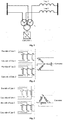
Fig. 1 is a schematic diagram of a wiring structure of a series compensation device suitable for double-circuit line in the present invention. -
Fig. 2 is a schematic diagram of a connection method of a star-connected winding grounded directly at the converter side of a multi-winding transformer in the present invention. -
Fig. 3 is a schematic diagram of a connection method of a delta-connected winding at the converter side of a multi-winding transformer in the present invention. -
Fig. 4 is a schematic diagram of a connection method of a multi-winding transformer with a balancing winding in the present invention. -
Fig. 5 is a schematic diagram of a wiring mode in which multiple converters are connected in the present invention. -
Fig. 6 is a schematic diagram of a wiring mode extended to a three-circuit line of the present invention. -
Fig. 7 is a schematic diagram of a wiring structure of the invention as an integral part of a unified power flow controller. - The specific embodiments of the present invention are described in detail below in conjunction with the accompanying drawings.
- The present invention provides a series compensation device suitable for double-circuit lines, which comprises at least one voltage source converter and one three-phase multi-winding transformer, wherein at least two windings of the three-phase multi-winding transformer are connected in series into the double-circuit lines respectively, and at least one winding is connected to an AC side of the voltage source converter. As shown in
Fig. 1 , the converter and double-circuit transmission lines are connected with three windings of the multi-winding transformer respectively, which constitute the minimum structure of the device. - According to the above-mentioned series compensation device suitable for double-circuit lines, three phases of the at least one winding of the three-phase multi-winding transformer that is connected to the voltage source converter are star-connected and grounded directly, star-connected and grounded via a resistor, or delta-connected.
Fig. 2 and Fig. 3 show respectively schematic diagrams of connection methods of a star-connected winding grounded directly and a delta-connected winding at converter side. - According to the above-mentioned series compensation device suitable for double-circuit lines, when the multi-winding transformer adopts a three-phase integrated structure, it includes a delta-connected balancing winding which operates without load.
Fig. 4 shows a schematic diagram of the multi-winding transformer with a balancing winding. - According to the above-mentioned series compensation device suitable for double-circuit lines, when there are a plurality of voltage source converters, the connection mode of multiple converters includes but not limited to: AC sides of all converters are connected in parallel and then connected to one winding of the transformer; all the converters are connected to multiple windings of transformer respectively, and each converter is connected to one corresponding winding of the transformer; as shown in
Fig. 5 , all the converters are divided into several groups, and each group is connected in parallel and then connected to one of multiple windings of the transformer. - According to the above-mentioned series compensation device suitable for double-circuit lines, there are but not limited to some or all of following devices arranged between converters and transformers: circuit breakers, isolators, arresters, and bypass devices.
- According to the above-mentioned series compensation device suitable for double-circuit lines, the bypass devices are configured in phase-to-phase or line-to-line of the AC systems, and comprise a breaker, a thyristor valve, or a spark gap.
- According to the above-mentioned series compensation device suitable for double-circuit lines, there are but not limited to some or all of following devices arranged between the multi-winding transformer and power transmission lines: circuit breakers, knife gates, lightning arresters, bypass devices and some or all devices.
- According to the above-mentioned series compensation device suitable for double-circuit lines, the series compensation device may be used for multiple-circuit lines, and accordingly, the multiple-circuit lines are connected to multiple windings of the transformer by split-phase series connection. As shown in
Fig. 6 , three-circuit lines are connected to three windings of the transformer at the line side by split-phase series connection, respectively, and two converters are connected in parallel and then connected to one winding of the transformer. - According to the above-mentioned series compensation device suitable for double-circuit lines, the series compensation device can be installed independently in a power transmission system, and the series compensation device can be connected to a power transmission line as a part of (but not limited to) a unified power flow controller, a convertible static compensator, a static synchronous series compensator, an inter-line power flow controller or a unified power quality regulator.
Fig. 7 shows a usage as part of the unified power flow controller. - By using the above-mentioned solution, the present invention comprises only one series transformer and can realize the connection for double-circuit lines through multiple windings. The transformer is divided into two parts: valve side windings and line side windings. In normal operation, the total current of the valve side windings (converted to the line side) is equal to the total current of the line side windings, while in normal operation, the total current of double-circuit lines is always far less than 2*rated current of the line. Therefore, the total current of all converters (converted to the line side) only needs to be selected as the maximum possible operation current of the line current. If a series compensation device is used for each circuit line, the current of the converter of each series compensation device (converted to the line side) must be equal to the rated current of the line. For double-circuit lines, the total current of the converter of two series compensation devices is equal to 2*rated current of the line; while using the solution of the present invention, the total current of the converter can be far less than 2*rated current line, that is, under the same rated output voltage, the converter capacity of the present solution is far less than that of conventional solution, which improves the operation efficiency of series compensation device, saves the cost of device, saves the occupied area and equipment cost of the series transformer, and improves economy and reliability for FACTS connected to power grid.
- The technical solutions of the present invention have been described with reference to the above embodiments, which are merely illustrative of the technical scope of the present invention. It should be understood by those skilled in the art that any modification or equivalent replacement can be made to the specific embodiments of the invention by those skilled in the art, these modification or equivalent replacement also fall within the scope of the claims of the invention.
Claims (9)
- A series compensation device for double-circuit lines, characterized in that: the device comprises at least one voltage source converter and one three-phase multi-winding transformer, wherein at least two windings of the three-phase multi-winding transformer are connected in series into the double-circuit lines respectively, and at least one winding of the three-phase multi-winding transformer is connected to an AC side of the voltage source converter.
- The series compensation device for double-circuit lines according to claim 1, characterized in that: three phases of the at least one winding of the three-phase multi-winding transformer that is connected to the voltage source converter are star-connected and grounded directly, star-connected and grounded via a resistor, or delta-connected.
- The series compensation device for double-circuit lines according to claim 1, characterized in that: when the three-phase multi-winding transformer adopts a three-phase integrated structure, the three-phase multi-winding transformer comprises a delta-connected balancing winding which operates without load.
- The series compensation device for double-circuit lines according to claim 1, characterized in that: when there are a plurality of voltage source converters, connection modes of the voltage source converters include: AC sides of all the voltage source converters are connected in parallel, and then connected to one winding of the three-phase multi-winding transformer; all the voltage source converters are connected to multiple windings of the three-phase multi-winding transformer respectively, and each voltage source converter is connected to one corresponding winding of the three-phase multi-winding transformer; all the voltage source converters are divided into several groups, and each group is connected in parallel and then connected to one of multiple windings of the three-phase multi-winding transformer.
- The series compensation device for double-circuit lines according to claim 1, characterized in that: some or all of following devices are arranged between the voltage source converter and the three-phase multi-winding transformer: circuit breakers, isolators, arresters, and bypass devices.
- The series compensation device for double-circuit lines according to claim 5, characterized in that: the bypass devices are configured in phase-to-phase or line-to-line of AC systems, and comprise a breaker, a thyristor valve or a spark gap.
- The series compensation device for double-circuit lines according to claim 1, characterized in that: some or all of following devices are arranged between the three-phase multi-winding transformer and power transmission lines: circuit breakers, isolators, arresters, and bypass devices.
- The series compensation device for double-circuit lines according to claim 1, characterized in that: when the series compensation device is used for multiple-circuit lines, the multiple-circuit lines are connected to multiple windings of the three-phase multi-winding transformer by split-phase series connection.
- The series compensation device for double-circuit lines according to claim 1, characterized in that: the series compensation device can be installed independently in a power transmission system, and the series compensation device can be connected to a power transmission line as a part of a unified power flow controller, a convertible static compensator, a static synchronous series compensator, an inter-line power flow controller, or a unified power quality regulator.
Applications Claiming Priority (2)
| Application Number | Priority Date | Filing Date | Title |
|---|---|---|---|
| CN201610677937.1A CN106130020B (en) | 2016-08-16 | 2016-08-16 | Series compensation device suitable for double-circuit line |
| PCT/CN2017/097478 WO2018033059A1 (en) | 2016-08-16 | 2017-08-15 | Series compensation device applicable to double-circuit line |
Publications (3)
| Publication Number | Publication Date |
|---|---|
| EP3480913A1 true EP3480913A1 (en) | 2019-05-08 |
| EP3480913A4 EP3480913A4 (en) | 2019-07-24 |
| EP3480913B1 EP3480913B1 (en) | 2021-05-12 |
Family
ID=57279281
Family Applications (1)
| Application Number | Title | Priority Date | Filing Date |
|---|---|---|---|
| EP17841031.2A Active EP3480913B1 (en) | 2016-08-16 | 2017-08-15 | Series compensation device applicable to double-circuit line |
Country Status (9)
| Country | Link |
|---|---|
| US (1) | US10396562B2 (en) |
| EP (1) | EP3480913B1 (en) |
| JP (1) | JP6727395B2 (en) |
| KR (1) | KR102000429B1 (en) |
| CN (1) | CN106130020B (en) |
| BR (1) | BR112019001837A2 (en) |
| ES (1) | ES2880973T3 (en) |
| RU (1) | RU2698469C1 (en) |
| WO (1) | WO2018033059A1 (en) |
Families Citing this family (4)
| Publication number | Priority date | Publication date | Assignee | Title |
|---|---|---|---|---|
| CN106130020B (en) * | 2016-08-16 | 2020-03-20 | 南京南瑞继保电气有限公司 | Series compensation device suitable for double-circuit line |
| CN106816881B (en) * | 2017-01-16 | 2020-09-04 | 全球能源互联网研究院有限公司 | A series compensation device and its capacity optimization method |
| CN109256777B (en) * | 2018-09-20 | 2021-05-14 | 东南大学 | IPFC topology suitable for power flow control of parallel double-circuit lines and its steady-state modeling method |
| CN114336660B (en) * | 2021-12-27 | 2024-04-12 | 江苏师范大学 | UPQC direct current prediction control method based on power angle |
Family Cites Families (19)
| Publication number | Priority date | Publication date | Assignee | Title |
|---|---|---|---|---|
| SE9403209L (en) * | 1994-09-23 | 1996-03-24 | Asea Brown Boveri | Series compensated inverter station |
| US6335613B1 (en) * | 2000-12-04 | 2002-01-01 | Abb T&D Technology Ltd. | Versatile power flow transformers for compensating power flow in a transmission line |
| US6804128B2 (en) * | 2002-11-07 | 2004-10-12 | Lionel O. Barthold | Current modulation of direct current transmission lines |
| KR100685481B1 (en) * | 2004-10-29 | 2007-02-23 | 한국전력공사 | Flexible power transmission system with enhanced protection of serial inverter |
| WO2007102758A1 (en) * | 2006-03-06 | 2007-09-13 | Abb Research Ltd | Power compensator |
| EP2051085A1 (en) * | 2007-10-19 | 2009-04-22 | ABB Research Ltd. | Method for fault location on series compensated power transmission lines with two-end unsychronized measurement |
| CN101272041B (en) * | 2008-04-14 | 2010-10-27 | 朱发国 | Wire-protecting and de-icing method of unit type high tension power line |
| CN103066542B (en) * | 2011-03-28 | 2015-10-28 | 清华大学 | Transmission line is at fortune deicing winterization system |
| WO2013126660A2 (en) * | 2012-02-24 | 2013-08-29 | Board Of Trustees Of Michigan State University | Transformer-less unified power flow controller |
| RU124070U1 (en) * | 2012-04-19 | 2013-01-10 | Леонид Абрамович Герман | DEVICE FOR LONGITUDINAL CAPACITY COMPENSATION OF AC TRACING SUBSTATION |
| CN103414185A (en) * | 2013-07-26 | 2013-11-27 | 南京南瑞继保电气有限公司 | Unified power flow controller and control method thereof |
| CN104065063A (en) * | 2014-07-04 | 2014-09-24 | 南京南瑞继保电气有限公司 | Unified power flow controller suitable for multiple lines |
| CN104113060A (en) * | 2014-07-23 | 2014-10-22 | 南京南瑞继保电气有限公司 | Convertible static synchronous series compensator |
| US10436831B2 (en) * | 2015-07-01 | 2019-10-08 | Abb Schweiz Ag | Fault location method for series-compensated double-circuit transmission lines |
| US10608545B2 (en) * | 2015-10-05 | 2020-03-31 | Resilient Power Systems, LLC | Power management utilizing synchronous common coupling |
| CN105680453B (en) * | 2016-03-14 | 2024-02-02 | 全球能源互联网研究院有限公司 | An improved parallel hybrid unified power flow controller |
| CN106130020B (en) * | 2016-08-16 | 2020-03-20 | 南京南瑞继保电气有限公司 | Series compensation device suitable for double-circuit line |
| CN205945059U (en) * | 2016-08-16 | 2017-02-08 | 南京南瑞继保电气有限公司 | Cascade compensation device suitable for two loop line ways |
| EP3432454B1 (en) * | 2017-07-21 | 2023-07-19 | Solaredge Technologies Ltd. | Multiple-output converter and control thereof |
-
2016
- 2016-08-16 CN CN201610677937.1A patent/CN106130020B/en active Active
-
2017
- 2017-08-15 BR BR112019001837-9A patent/BR112019001837A2/en not_active Application Discontinuation
- 2017-08-15 ES ES17841031T patent/ES2880973T3/en active Active
- 2017-08-15 JP JP2019500849A patent/JP6727395B2/en active Active
- 2017-08-15 KR KR1020197001501A patent/KR102000429B1/en active Active
- 2017-08-15 EP EP17841031.2A patent/EP3480913B1/en active Active
- 2017-08-15 WO PCT/CN2017/097478 patent/WO2018033059A1/en not_active Ceased
- 2017-08-15 US US16/319,300 patent/US10396562B2/en active Active
- 2017-08-15 RU RU2019103655A patent/RU2698469C1/en active
Also Published As
| Publication number | Publication date |
|---|---|
| KR20190020052A (en) | 2019-02-27 |
| JP6727395B2 (en) | 2020-07-22 |
| EP3480913A4 (en) | 2019-07-24 |
| JP2019525703A (en) | 2019-09-05 |
| RU2698469C1 (en) | 2019-08-27 |
| EP3480913B1 (en) | 2021-05-12 |
| WO2018033059A1 (en) | 2018-02-22 |
| CN106130020A (en) | 2016-11-16 |
| US20190157871A1 (en) | 2019-05-23 |
| CN106130020B (en) | 2020-03-20 |
| KR102000429B1 (en) | 2019-07-15 |
| US10396562B2 (en) | 2019-08-27 |
| BR112019001837A2 (en) | 2019-05-07 |
| ES2880973T3 (en) | 2021-11-26 |
Similar Documents
| Publication | Publication Date | Title |
|---|---|---|
| CA2622057C (en) | Apparatus for electrical power transmission | |
| WO2018033058A1 (en) | Series compensation device | |
| EP2183848B1 (en) | Voltage source converter for high voltage direct current power transmission | |
| EP1787383B1 (en) | Convertible high voltage direct current installation | |
| DE112016004548T5 (en) | Power management using synchronous shared coupling | |
| US20080252142A1 (en) | Apparatus for Electrical Power Transmission | |
| EP0809876B1 (en) | Series-compensated converter station | |
| US10396562B2 (en) | Series compensation device applicable to double-circuit line | |
| CN106208112B (en) | Electric locomotive test wire balance power supply system | |
| CN103956763A (en) | Flexible DC converter station | |
| Ottosson et al. | Modular back-to-back HVDC, with capacitor commutated converters (CCC) | |
| CN106159975B (en) | Series compensation device suitable for multi-circuit line | |
| CN105281338B (en) | Alternating voltage measuring point optimal configuration method and structure for reactive power control of converter station | |
| Yang et al. | Installation, system-level control strategy and commissioning of the Nanjing UPFC project | |
| CN205945076U (en) | Cascade compensation device | |
| CN205945059U (en) | Cascade compensation device suitable for two loop line ways | |
| CN205986167U (en) | Cascade compensation device suitable for many loop lines way | |
| CN213958748U (en) | Rectification and harmonic control transformer | |
| CN210985973U (en) | Drilling oil power-change control system directly driven by medium-voltage frequency conversion | |
| BG3844U1 (en) | Centralized device for energy saving in the three-phase network of the enterprise | |
| CN205123272U (en) | Substation equipment system | |
| CN115603355A (en) | A defense device for multi-DC commutation failure in AC-DC hybrid power grid | |
| CN201426094Y (en) | High-voltage frequency converter with N plus 1 unit redundancy structure | |
| Schmitt et al. | System performance and basic design aspects for the Etzenricht 600 MW back-to-back HVDC converter station | |
| CN108736494A (en) | A kind of electric locomotive test wire balanced feeding system |
Legal Events
| Date | Code | Title | Description |
|---|---|---|---|
| STAA | Information on the status of an ep patent application or granted ep patent |
Free format text: STATUS: THE INTERNATIONAL PUBLICATION HAS BEEN MADE |
|
| PUAI | Public reference made under article 153(3) epc to a published international application that has entered the european phase |
Free format text: ORIGINAL CODE: 0009012 |
|
| STAA | Information on the status of an ep patent application or granted ep patent |
Free format text: STATUS: REQUEST FOR EXAMINATION WAS MADE |
|
| 17P | Request for examination filed |
Effective date: 20190129 |
|
| AK | Designated contracting states |
Kind code of ref document: A1 Designated state(s): AL AT BE BG CH CY CZ DE DK EE ES FI FR GB GR HR HU IE IS IT LI LT LU LV MC MK MT NL NO PL PT RO RS SE SI SK SM TR |
|
| AX | Request for extension of the european patent |
Extension state: BA ME |
|
| A4 | Supplementary search report drawn up and despatched |
Effective date: 20190624 |
|
| RIC1 | Information provided on ipc code assigned before grant |
Ipc: H02J 3/00 20060101AFI20190617BHEP Ipc: H02J 3/18 20060101ALI20190617BHEP |
|
| DAV | Request for validation of the european patent (deleted) | ||
| DAX | Request for extension of the european patent (deleted) | ||
| GRAP | Despatch of communication of intention to grant a patent |
Free format text: ORIGINAL CODE: EPIDOSNIGR1 |
|
| STAA | Information on the status of an ep patent application or granted ep patent |
Free format text: STATUS: GRANT OF PATENT IS INTENDED |
|
| INTG | Intention to grant announced |
Effective date: 20201110 |
|
| GRAS | Grant fee paid |
Free format text: ORIGINAL CODE: EPIDOSNIGR3 |
|
| GRAA | (expected) grant |
Free format text: ORIGINAL CODE: 0009210 |
|
| STAA | Information on the status of an ep patent application or granted ep patent |
Free format text: STATUS: THE PATENT HAS BEEN GRANTED |
|
| AK | Designated contracting states |
Kind code of ref document: B1 Designated state(s): AL AT BE BG CH CY CZ DE DK EE ES FI FR GB GR HR HU IE IS IT LI LT LU LV MC MK MT NL NO PL PT RO RS SE SI SK SM TR |
|
| REG | Reference to a national code |
Ref country code: GB Ref legal event code: FG4D |
|
| REG | Reference to a national code |
Ref country code: CH Ref legal event code: EP |
|
| REG | Reference to a national code |
Ref country code: DE Ref legal event code: R096 Ref document number: 602017038622 Country of ref document: DE |
|
| REG | Reference to a national code |
Ref country code: IE Ref legal event code: FG4D |
|
| REG | Reference to a national code |
Ref country code: AT Ref legal event code: REF Ref document number: 1392819 Country of ref document: AT Kind code of ref document: T Effective date: 20210615 |
|
| REG | Reference to a national code |
Ref country code: LT Ref legal event code: MG9D |
|
| REG | Reference to a national code |
Ref country code: GR Ref legal event code: EP Ref document number: 20210402121 Country of ref document: GR Effective date: 20210915 |
|
| REG | Reference to a national code |
Ref country code: AT Ref legal event code: MK05 Ref document number: 1392819 Country of ref document: AT Kind code of ref document: T Effective date: 20210512 |
|
| REG | Reference to a national code |
Ref country code: NL Ref legal event code: MP Effective date: 20210512 |
|
| PG25 | Lapsed in a contracting state [announced via postgrant information from national office to epo] |
Ref country code: HR Free format text: LAPSE BECAUSE OF FAILURE TO SUBMIT A TRANSLATION OF THE DESCRIPTION OR TO PAY THE FEE WITHIN THE PRESCRIBED TIME-LIMIT Effective date: 20210512 Ref country code: BG Free format text: LAPSE BECAUSE OF FAILURE TO SUBMIT A TRANSLATION OF THE DESCRIPTION OR TO PAY THE FEE WITHIN THE PRESCRIBED TIME-LIMIT Effective date: 20210812 Ref country code: AT Free format text: LAPSE BECAUSE OF FAILURE TO SUBMIT A TRANSLATION OF THE DESCRIPTION OR TO PAY THE FEE WITHIN THE PRESCRIBED TIME-LIMIT Effective date: 20210512 Ref country code: FI Free format text: LAPSE BECAUSE OF FAILURE TO SUBMIT A TRANSLATION OF THE DESCRIPTION OR TO PAY THE FEE WITHIN THE PRESCRIBED TIME-LIMIT Effective date: 20210512 Ref country code: LT Free format text: LAPSE BECAUSE OF FAILURE TO SUBMIT A TRANSLATION OF THE DESCRIPTION OR TO PAY THE FEE WITHIN THE PRESCRIBED TIME-LIMIT Effective date: 20210512 |
|
| REG | Reference to a national code |
Ref country code: ES Ref legal event code: FG2A Ref document number: 2880973 Country of ref document: ES Kind code of ref document: T3 Effective date: 20211126 |
|
| PG25 | Lapsed in a contracting state [announced via postgrant information from national office to epo] |
Ref country code: SE Free format text: LAPSE BECAUSE OF FAILURE TO SUBMIT A TRANSLATION OF THE DESCRIPTION OR TO PAY THE FEE WITHIN THE PRESCRIBED TIME-LIMIT Effective date: 20210512 Ref country code: RS Free format text: LAPSE BECAUSE OF FAILURE TO SUBMIT A TRANSLATION OF THE DESCRIPTION OR TO PAY THE FEE WITHIN THE PRESCRIBED TIME-LIMIT Effective date: 20210512 Ref country code: PL Free format text: LAPSE BECAUSE OF FAILURE TO SUBMIT A TRANSLATION OF THE DESCRIPTION OR TO PAY THE FEE WITHIN THE PRESCRIBED TIME-LIMIT Effective date: 20210512 Ref country code: PT Free format text: LAPSE BECAUSE OF FAILURE TO SUBMIT A TRANSLATION OF THE DESCRIPTION OR TO PAY THE FEE WITHIN THE PRESCRIBED TIME-LIMIT Effective date: 20210913 Ref country code: LV Free format text: LAPSE BECAUSE OF FAILURE TO SUBMIT A TRANSLATION OF THE DESCRIPTION OR TO PAY THE FEE WITHIN THE PRESCRIBED TIME-LIMIT Effective date: 20210512 Ref country code: NO Free format text: LAPSE BECAUSE OF FAILURE TO SUBMIT A TRANSLATION OF THE DESCRIPTION OR TO PAY THE FEE WITHIN THE PRESCRIBED TIME-LIMIT Effective date: 20210812 Ref country code: IS Free format text: LAPSE BECAUSE OF FAILURE TO SUBMIT A TRANSLATION OF THE DESCRIPTION OR TO PAY THE FEE WITHIN THE PRESCRIBED TIME-LIMIT Effective date: 20210912 |
|
| PG25 | Lapsed in a contracting state [announced via postgrant information from national office to epo] |
Ref country code: NL Free format text: LAPSE BECAUSE OF FAILURE TO SUBMIT A TRANSLATION OF THE DESCRIPTION OR TO PAY THE FEE WITHIN THE PRESCRIBED TIME-LIMIT Effective date: 20210512 |
|
| PG25 | Lapsed in a contracting state [announced via postgrant information from national office to epo] |
Ref country code: SK Free format text: LAPSE BECAUSE OF FAILURE TO SUBMIT A TRANSLATION OF THE DESCRIPTION OR TO PAY THE FEE WITHIN THE PRESCRIBED TIME-LIMIT Effective date: 20210512 Ref country code: SM Free format text: LAPSE BECAUSE OF FAILURE TO SUBMIT A TRANSLATION OF THE DESCRIPTION OR TO PAY THE FEE WITHIN THE PRESCRIBED TIME-LIMIT Effective date: 20210512 Ref country code: EE Free format text: LAPSE BECAUSE OF FAILURE TO SUBMIT A TRANSLATION OF THE DESCRIPTION OR TO PAY THE FEE WITHIN THE PRESCRIBED TIME-LIMIT Effective date: 20210512 Ref country code: RO Free format text: LAPSE BECAUSE OF FAILURE TO SUBMIT A TRANSLATION OF THE DESCRIPTION OR TO PAY THE FEE WITHIN THE PRESCRIBED TIME-LIMIT Effective date: 20210512 Ref country code: DK Free format text: LAPSE BECAUSE OF FAILURE TO SUBMIT A TRANSLATION OF THE DESCRIPTION OR TO PAY THE FEE WITHIN THE PRESCRIBED TIME-LIMIT Effective date: 20210512 Ref country code: CZ Free format text: LAPSE BECAUSE OF FAILURE TO SUBMIT A TRANSLATION OF THE DESCRIPTION OR TO PAY THE FEE WITHIN THE PRESCRIBED TIME-LIMIT Effective date: 20210512 |
|
| REG | Reference to a national code |
Ref country code: DE Ref legal event code: R097 Ref document number: 602017038622 Country of ref document: DE |
|
| REG | Reference to a national code |
Ref country code: DE Ref legal event code: R119 Ref document number: 602017038622 Country of ref document: DE |
|
| PLBE | No opposition filed within time limit |
Free format text: ORIGINAL CODE: 0009261 |
|
| STAA | Information on the status of an ep patent application or granted ep patent |
Free format text: STATUS: NO OPPOSITION FILED WITHIN TIME LIMIT |
|
| REG | Reference to a national code |
Ref country code: CH Ref legal event code: PL |
|
| PG25 | Lapsed in a contracting state [announced via postgrant information from national office to epo] |
Ref country code: MC Free format text: LAPSE BECAUSE OF FAILURE TO SUBMIT A TRANSLATION OF THE DESCRIPTION OR TO PAY THE FEE WITHIN THE PRESCRIBED TIME-LIMIT Effective date: 20210512 |
|
| 26N | No opposition filed |
Effective date: 20220215 |
|
| REG | Reference to a national code |
Ref country code: BE Ref legal event code: MM Effective date: 20210831 |
|
| PG25 | Lapsed in a contracting state [announced via postgrant information from national office to epo] |
Ref country code: LI Free format text: LAPSE BECAUSE OF NON-PAYMENT OF DUE FEES Effective date: 20210831 Ref country code: CH Free format text: LAPSE BECAUSE OF NON-PAYMENT OF DUE FEES Effective date: 20210831 |
|
| PG25 | Lapsed in a contracting state [announced via postgrant information from national office to epo] |
Ref country code: IS Free format text: LAPSE BECAUSE OF FAILURE TO SUBMIT A TRANSLATION OF THE DESCRIPTION OR TO PAY THE FEE WITHIN THE PRESCRIBED TIME-LIMIT Effective date: 20210912 Ref country code: LU Free format text: LAPSE BECAUSE OF NON-PAYMENT OF DUE FEES Effective date: 20210815 Ref country code: AL Free format text: LAPSE BECAUSE OF FAILURE TO SUBMIT A TRANSLATION OF THE DESCRIPTION OR TO PAY THE FEE WITHIN THE PRESCRIBED TIME-LIMIT Effective date: 20210512 |
|
| PG25 | Lapsed in a contracting state [announced via postgrant information from national office to epo] |
Ref country code: DE Free format text: LAPSE BECAUSE OF NON-PAYMENT OF DUE FEES Effective date: 20220301 Ref country code: BE Free format text: LAPSE BECAUSE OF NON-PAYMENT OF DUE FEES Effective date: 20210831 |
|
| PG25 | Lapsed in a contracting state [announced via postgrant information from national office to epo] |
Ref country code: CY Free format text: LAPSE BECAUSE OF FAILURE TO SUBMIT A TRANSLATION OF THE DESCRIPTION OR TO PAY THE FEE WITHIN THE PRESCRIBED TIME-LIMIT Effective date: 20210512 |
|
| PG25 | Lapsed in a contracting state [announced via postgrant information from national office to epo] |
Ref country code: HU Free format text: LAPSE BECAUSE OF FAILURE TO SUBMIT A TRANSLATION OF THE DESCRIPTION OR TO PAY THE FEE WITHIN THE PRESCRIBED TIME-LIMIT; INVALID AB INITIO Effective date: 20170815 |
|
| PG25 | Lapsed in a contracting state [announced via postgrant information from national office to epo] |
Ref country code: MK Free format text: LAPSE BECAUSE OF FAILURE TO SUBMIT A TRANSLATION OF THE DESCRIPTION OR TO PAY THE FEE WITHIN THE PRESCRIBED TIME-LIMIT Effective date: 20210512 |
|
| PG25 | Lapsed in a contracting state [announced via postgrant information from national office to epo] |
Ref country code: MT Free format text: LAPSE BECAUSE OF FAILURE TO SUBMIT A TRANSLATION OF THE DESCRIPTION OR TO PAY THE FEE WITHIN THE PRESCRIBED TIME-LIMIT Effective date: 20210512 |
|
| PGFP | Annual fee paid to national office [announced via postgrant information from national office to epo] |
Ref country code: ES Payment date: 20250908 Year of fee payment: 9 |
|
| PGFP | Annual fee paid to national office [announced via postgrant information from national office to epo] |
Ref country code: GR Payment date: 20250729 Year of fee payment: 9 |
|
| PGFP | Annual fee paid to national office [announced via postgrant information from national office to epo] |
Ref country code: TR Payment date: 20250808 Year of fee payment: 9 Ref country code: IT Payment date: 20250808 Year of fee payment: 9 |
|
| PGFP | Annual fee paid to national office [announced via postgrant information from national office to epo] |
Ref country code: GB Payment date: 20250826 Year of fee payment: 9 |
|
| PGFP | Annual fee paid to national office [announced via postgrant information from national office to epo] |
Ref country code: FR Payment date: 20250828 Year of fee payment: 9 |
|
| PGFP | Annual fee paid to national office [announced via postgrant information from national office to epo] |
Ref country code: IE Payment date: 20250728 Year of fee payment: 9 |