EP3480733A1 - Image processing system and image processing method - Google Patents
Image processing system and image processing method Download PDFInfo
- Publication number
- EP3480733A1 EP3480733A1 EP18204417.2A EP18204417A EP3480733A1 EP 3480733 A1 EP3480733 A1 EP 3480733A1 EP 18204417 A EP18204417 A EP 18204417A EP 3480733 A1 EP3480733 A1 EP 3480733A1
- Authority
- EP
- European Patent Office
- Prior art keywords
- article
- basic shape
- processor
- camera
- image processing
- Prior art date
- Legal status (The legal status is an assumption and is not a legal conclusion. Google has not performed a legal analysis and makes no representation as to the accuracy of the status listed.)
- Withdrawn
Links
Images




Classifications
-
- G—PHYSICS
- G06—COMPUTING OR CALCULATING; COUNTING
- G06V—IMAGE OR VIDEO RECOGNITION OR UNDERSTANDING
- G06V10/00—Arrangements for image or video recognition or understanding
- G06V10/10—Image acquisition
-
- G—PHYSICS
- G06—COMPUTING OR CALCULATING; COUNTING
- G06T—IMAGE DATA PROCESSING OR GENERATION, IN GENERAL
- G06T7/00—Image analysis
- G06T7/50—Depth or shape recovery
- G06T7/55—Depth or shape recovery from multiple images
- G06T7/593—Depth or shape recovery from multiple images from stereo images
-
- G—PHYSICS
- G06—COMPUTING OR CALCULATING; COUNTING
- G06T—IMAGE DATA PROCESSING OR GENERATION, IN GENERAL
- G06T7/00—Image analysis
- G06T7/70—Determining position or orientation of objects or cameras
-
- H—ELECTRICITY
- H04—ELECTRIC COMMUNICATION TECHNIQUE
- H04N—PICTORIAL COMMUNICATION, e.g. TELEVISION
- H04N23/00—Cameras or camera modules comprising electronic image sensors; Control thereof
- H04N23/56—Cameras or camera modules comprising electronic image sensors; Control thereof provided with illuminating means
-
- H—ELECTRICITY
- H04—ELECTRIC COMMUNICATION TECHNIQUE
- H04N—PICTORIAL COMMUNICATION, e.g. TELEVISION
- H04N23/00—Cameras or camera modules comprising electronic image sensors; Control thereof
- H04N23/60—Control of cameras or camera modules
- H04N23/66—Remote control of cameras or camera parts, e.g. by remote control devices
-
- G—PHYSICS
- G06—COMPUTING OR CALCULATING; COUNTING
- G06T—IMAGE DATA PROCESSING OR GENERATION, IN GENERAL
- G06T2207/00—Indexing scheme for image analysis or image enhancement
- G06T2207/10—Image acquisition modality
- G06T2207/10004—Still image; Photographic image
- G06T2207/10012—Stereo images
-
- G—PHYSICS
- G06—COMPUTING OR CALCULATING; COUNTING
- G06T—IMAGE DATA PROCESSING OR GENERATION, IN GENERAL
- G06T2207/00—Indexing scheme for image analysis or image enhancement
- G06T2207/10—Image acquisition modality
- G06T2207/10028—Range image; Depth image; 3D point clouds
-
- G—PHYSICS
- G06—COMPUTING OR CALCULATING; COUNTING
- G06T—IMAGE DATA PROCESSING OR GENERATION, IN GENERAL
- G06T7/00—Image analysis
- G06T7/50—Depth or shape recovery
- G06T7/521—Depth or shape recovery from laser ranging, e.g. using interferometry; from the projection of structured light
-
- H—ELECTRICITY
- H04—ELECTRIC COMMUNICATION TECHNIQUE
- H04N—PICTORIAL COMMUNICATION, e.g. TELEVISION
- H04N13/00—Stereoscopic video systems; Multi-view video systems; Details thereof
- H04N13/20—Image signal generators
- H04N13/204—Image signal generators using stereoscopic image cameras
-
- H—ELECTRICITY
- H04—ELECTRIC COMMUNICATION TECHNIQUE
- H04N—PICTORIAL COMMUNICATION, e.g. TELEVISION
- H04N13/00—Stereoscopic video systems; Multi-view video systems; Details thereof
- H04N2013/0074—Stereoscopic image analysis
- H04N2013/0081—Depth or disparity estimation from stereoscopic image signals
-
- H—ELECTRICITY
- H04—ELECTRIC COMMUNICATION TECHNIQUE
- H04N—PICTORIAL COMMUNICATION, e.g. TELEVISION
- H04N23/00—Cameras or camera modules comprising electronic image sensors; Control thereof
- H04N23/90—Arrangement of cameras or camera modules, e.g. multiple cameras in TV studios or sports stadiums
Definitions
- the present invention relates to the field of an image processing technology in general, and embodiments described herein relate in particular to an image processing system and an image processing method.
- An image processing system for executing such a technique acquires an image of an article and generates dictionary information in advance.
- the number of images necessary for generating the dictionary information and an imaging angle are different for each article. Therefore, the image processing system has a problem of capturing unnecessary images.
- an image processing system comprising:
- the imaging parameters include an angle at which the article is imaged.
- system further comprises:
- the input/output device includes at least one of a keypad, a keyboard, or a touch pad.
- the processor is configured to determine the basic shape.
- system further comprises:
- the distance sensor includes a three-dimensional camera.
- the invention also relates to an image processing system comprising:
- the imaging device includes a turntable configured to support and rotate the article.
- the imaging device includes at least one light unit configured to illuminate the article.
- the imaging parameters include an angle at which the article is imaged.
- the system further comprises:
- the processor is configured to determine the basic shape.
- system further comprises:
- the basic shape is a category of the outline of the article.
- the basic shape is any one of a cube, a rectangular parallelepiped, a polygonal prism, a cylinder, a cone, a sphere, a polygonal cone or a plane.
- the present invention also concerns an image processing method, comprising:
- the imaging parameters include an angle at which the article is imaged.
- the image processing method further comprises: measuring a distance to each part of the article, wherein the basic shape is determined based on the distance measured.
- an image processing system and an image processing method capable of properly capturing an image for generating dictionary information are provided.
- an image processing system includes a camera interface and a processor.
- the camera interface acquires a captured image from a camera that images an article.
- the processor acquires a basic shape of the article and acquires an image captured with imaging parameters corresponding to the basic shape from the camera through the camera interface.
- the image processing system images an article in order to generate dictionary information.
- an article is set at a predetermined position by an operator or the like.
- the image processing system images the set article and acquires an image of the article.
- the dictionary information is information used for object recognition. That is, the dictionary information is information for specifying an object by matching the image of the object therewith.
- the dictionary information may be an image of an article or information indicating a feature amount of an image of an article.
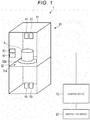
- FIG. 1 illustrates a configuration example of an image processing system 1.
- the image processing system 1 includes a control device 10, an input/output device 20, an imaging device 30, and the like.
- the control device 10 is communicably connected to the input/output device 20 and the imaging device 30.
- the image processing system 1 images an article A.
- the control device 10 controls the entire image processing system 1.
- the control device 10 images the article A by using the imaging device 30 based on an instruction from the operator or the like. For example, the control device 10 receives an instruction input from the operator through the input/output device 20. Further, the control device 10 displays various information to the operator through the input/output device 20.
- the input/output device 20 is an interface for receiving an instruction input from the operator and displaying various information to the operator.
- the input/output device 20 is constituted with an operation unit that receives an instruction input and a display unit that displays information.
- the input/output device 20 transmits a signal indicating an operation received from the operator to the control device 10 as the operation of the operation unit.
- the operation unit has a touch panel.
- the input/output device 20 displays various information as the operation of the display unit under the control of the control device 10.
- the display unit is constituted with a liquid crystal monitor.
- the display unit is integrally formed with a touch panel as the operation unit.
- the operation unit may be constituted with a keyboard or a numeric keypad.
- the imaging device 30 images the article A under the control from the control device 10.
- the imaging device 30 images the article A from various angles.
- the imaging device 30 is constituted with a housing 31, a turntable 32, cameras 41 to 43, lighting units 51 to 53, and the like.
- the imaging device 30 may further have a configuration according to necessity, or a specific configuration may be excluded from the imaging device 30.
- the housing 31 is a frame that forms the outer shape of the imaging device 30.
- the housing 31 is made of resin or the like, for example.
- the housing 31 is formed in a rectangular parallelepiped shape.
- the housing 31 is provided with a partition 31a in the middle part in a vertical direction.
- the partition 31a is formed horizontally.
- the partition 31a is formed in a rectangular shape according to the shape of the housing 31.
- the partition 31a is formed of a transparent material.
- the partition 31a is an acrylic plate or the like.
- the turntable 32, the cameras 41 to 43, and the lighting units 51 to 53 are formed inside the housing 31.
- the turntable 32 is formed on the partition 31a.
- the turntable 32 rotates the article A placed on the top side under the control from the control device 10.
- the turntable 32 is constituted by a disk 32a on which the article A is placed and a drive unit that rotates the disk.
- the disk 32a is formed of a transparent material.
- the disk 32a is an acrylic plate or the like.
- the cameras 41 to 43 images the article A under the control from the control device 10.
- the cameras 41 to 43 transmit captured images obtained by imaging the article A to the control device 10.
- the cameras 41 to 43 are charge coupled device (CCD) cameras and the like.
- the camera 41 (a first camera) images the article A from a predetermined direction.
- the camera 41 images the top side of the article A.
- the camera 41 is installed downward on the top side of the housing 31.
- the camera 41 images the article A from above.
- the camera 42 (a second camera) images the article A from a direction orthogonal to the predetermined direction.
- the camera 42 images the side of the article A.
- the camera 41 is installed horizontally on the side of the housing 31.
- the camera 41 images the article A from the side part.
- the camera 43 (a third camera) images the article A in a direction opposite to the predetermined direction.
- the camera 43 images the bottom side of the article A.
- the camera 41 is installed upward on the bottom side of the housing 31.
- the camera 41 images the article A from the bottom part.
- the lighting units 51 to 53 illuminate the article A under the control from the control device 10.
- the lighting units 51 to 53 are constituted with light emitting diodes (LED) or the like.
- the lighting unit 51 illuminates an area to be imaged by the camera 41. That is, the lighting unit 51 illuminates the top side of the article A.
- the lighting unit 51 is installed downward on the top side of the housing 31. The lighting unit 51 illuminates the article A from above.
- the lighting unit 52 illuminates an area to be imaged by the camera 42. That is, the lighting unit 52 illuminates the side of the article A.
- the lighting unit 52 is installed laterally on the side of the housing 31. The lighting unit 52 illuminates the article A from the side part.
- the lighting unit 53 illuminates an area to be imaged by the camera 43. That is, the lighting unit 53 illuminates the bottom side of the article A.
- the lighting unit 53 is installed upward on the bottom side of the housing 31. The lighting unit 53 illuminates the article A from the bottom.
- control device 10 Next, a configuration example of the control device 10 will be described.
- FIG. 2 is a block diagram showing a configuration example of the control device 10.
- the control device 10 includes a processor 11, a ROM 12, a RAM 13, an NVM 14, a table interface 15, a camera interface 16, a lighting interface 17, an input/output interface 18, and the like.
- the processor 11, the ROM 12, the RAM 13, the NVM 14, the table interface 15, the camera interface 16, the lighting interface 17, and the input/output interface 18 are connected to each other via a data bus or the like.
- control device 10 may further have a configuration according to the particular application, or a specific configuration may be excluded from the control device 10.
- the processor 11 has a function of controlling the overall operation of the control device 10.
- the processor 11 may include an internal cache and various interfaces, and the like.
- the processor 11 realizes various processes by executing programs stored in the internal memory, the ROM 12 or the NVM 14 in advance.
- Some of the various functions realized by the processor 11 executing the programs may be realized by a hardware circuit.
- the processor 11 controls functions executed by the hardware circuit.
- the ROM 12 is a nonvolatile memory in which a control program, control data, and the like are stored in advance.
- the control program and the control data stored in the ROM 12 are incorporated in advance according to the specification of the control device 10.
- the ROM 12 stores, for example, a program (for example, BIOS) for controlling the circuit board of the control device 10.
- the RAM 13 is a volatile memory.
- the RAM 13 temporarily stores data under processing of the processor 11 and the like.
- the RAM 13 stores various application programs based on instructions from the processor 11. Further, the RAM 13 may store data necessary for executing the application programs, execution results of the application programs, and the like.
- the NVM 14 is a nonvolatile memory capable of writing and rewriting data.
- the NVM 14 is constituted with, for example, a hard disk drive (HDD), a solid state drive (SSD), an EEPROM (registered trademark) or a flash memory.
- the NVM 14 stores control programs, applications, various data, and the like according to the operational application of the control device 10.
- the NVM 14 stores a parameter table.
- the parameter table will be described later.
- the table interface 15 is an interface for transmitting and receiving data to and from the turntable 32.
- the table interface 15 transmits a signal for rotating the disk 32a under the control of the processor 11. Further, the table interface 15 may receive a signal indicating the angle of the disk 32a from the turntable 32.
- the table interface 15 may support a USB connection.
- the camera interface 16 is an interface for transmitting and receiving data to and from the cameras 41 to 43.
- the camera interface 16 transmits a signal for instructing imaging to the cameras 41 to 43 under the control of the processor 11.
- the camera interface 16 acquires captured images obtained by imaging from the cameras 41 to 43.
- the camera interface 16 may support a USB connection.
- the lighting interface 17 is an interface for transmitting and receiving data to and from the lighting units 51 to 53.
- the lighting interface 17 transmits a signal for instructing lighting to the lighting units 51 to 53 under the control of the processor 11.
- the lighting interface 17 may support a USB connection.
- the input/output interface 18 is an interface for exchanging data with the input/output device 20.
- the input/output interface 18 receives a signal for indicating an operation received from the operator from the input/output device 20.
- the input/output interface 18 transmits information indicating a screen to be displayed to the operator to the input/output device 20 under the control of the processor 11.
- the input/output interface 18 may support a USB connection.
- the parameter table shows imaging parameters related to the imaging of the article for each basic shape of the article.
- the basic shape is a category of the outline of the article. That is, the basic shape is an approximate shape of the outer shape of the article.
- the basic shape is a cube, a rectangular parallelepiped, a polygonal prism, a cylinder, a cone, a sphere, a polygonal cone or a plane.
- the content of the basic shape is not limited to a specific configuration.
- the imaging parameters are parameters for capturing an image necessary for generating dictionary information of the article.
- FIG. 3 shows an example of a parameter table.
- the parameter table stores "Basic Shape” and "Imaging Parameter” in association with each other.
- “Basic Shape” indicates the names of a basic shape. Further, the "Basic Shape” may be an ID or the like indicating the basic shape.
- Imaging Parameter indicates imaging parameters of a corresponding basic shape.
- Imaging Parameter stores “Number of Captured Images”, “Imaging Angle”, and “Lighting Position” in association with each other.
- the "Imaging Parameter” may further include a configuration according to the particular application, or a specific configuration may be excluded from the “Imaging Parameter”.
- “Number of Captured Images” indicates the number of images to be captured.
- “Imaging Angle” indicates the angle at which a commodity is imaged. For example, “Imaging Angle” indicates a side or the like for imaging an article.
- Lighting Position indicates a lighting unit to be turned on when the article is imaged.
- the “Lighting Position” may indicate a lighting unit to be turned on at each imaging angle.
- the parameter table indicates, "6 pieces” (number of images to be captured), “front side/back side/top side/bottom side/left side/right side” (imaging angles), and “the same directions as imaging angles” (lighting position) as the imaging parameters of "cube". That is, the parameter table indicates 6 pieces of image of "cubic” article to be captured. Further, the parameter table indicates that the "cubic" article is to be imaged from the front side/back side/top side/bottom side/left side/right side. Further, in the case of imaging an article of "cube", the parameter table indicates that the lighting unit for illuminating the direction in which the camera images is to be turned on.
- control device 10 functions realized by the control device 10 will be described.
- the functions realized by the control device 10 are realized by the processor 11 executing a program stored in the NVM 14 or the like.
- the processor 11 has a function of receiving an input of the basic shape of the article A set on the turntable 32.
- the processor 11 receives an input of the basic shape of the article A through the input/output device 20.
- the processor 11 sets the input basic shape.
- FIG. 4 shows an example of a screen to be displayed when the input/output device 20 receives an input of a basic shape. As shown in FIG. 4 , the input/output device 20 displays icons 61 to 63.
- the icon 61 receives an input of "cube” as a basic shape.
- the icon 62 receives an input of "cylinder” as a basic shape.
- the icon 63 receives an input that the basic shape is unknown.
- the input/output device 20 may display an icon for receiving an input of another basic shape.
- the processor 11 When detecting the tap on the icon 61 or 62, the processor 11 acquires the basic shape corresponding to the tapped icon 61 or 62. Further, when detecting the tap on the icon 63, the processor 11 recognizes that the basic shape is unknown.
- the processor 11 has a function of acquiring imaging parameters corresponding to the basic shape of the article A.
- the processor 11 refers to the parameter table and acquires imaging parameters corresponding to the basic shape.
- the processor 11 sets the acquired imaging parameters.
- the processor 11 may acquire predetermined imaging parameters.
- the processor 11 has a function of imaging the article A according to the acquired imaging parameters.
- the processor 11 uses the cameras 41 to 43, the lighting units 51 to 53, and the turntable 32 to image the article A.
- the processor 11 images the "front side/back side/top side/bottom side/left side/right side” of the article A.
- the processor 11 turns on the lighting units 51 to 53 corresponding to the respective cameras 41 to 43.
- the processor 11 turns on the lighting unit 51.
- the processor 11 images the "top side” of the article A by using the camera 41.
- the processor 11 turns on the lighting unit 53.
- the processor 11 uses the camera 43 to image the "bottom side" of the article A.
- the processor 11 When imaging the "bottom side” of the article A, the processor 11 directs the article A in a predetermined direction by using the turntable 32. When the article A is directed in the predetermined direction, the processor 11 turns on the lighting unit 52. When the lighting unit 52 is turned on, the processor 11 images a predetermined side (front side, back side, left side or right side) of the article A by using the camera 42.
- the processor 11 uses the turntable 32 to direct the article A in the predetermined direction.
- the processor 11 uses the camera 42 to image the other side (front side, back side, left side or right side) of the article A.
- the processor 11 repeats the above operation to image the front side, back side, left side, and right side of the article A.
- the processor 11 may simultaneously image the top side, the bottom side, and one side of the article A.
- the processor 11 may store the captured image in the NVM 14. Further, the processor 11 may store the captured image in an external memory. In addition, the processor 11 may transmit the captured image to the external device.
- control device 10 Next, an operation example of the control device 10 will be described.
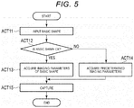
- FIG. 5 is a flowchart for describing an operation example of the control device 10. Here, it is assumed that the article A is set on the turntable 32.
- the processor 11 of the control device 10 receives the input of the basic shape of the article A through the input/output device 20 (ACT 11).
- the processor 11 determines whether the basic shape of the article A has been acquired (ACT 12).
- the processor 11 refers to the parameter table and acquires imaging parameters corresponding to the acquired basic shape (ACT 13).
- the processor 11 acquires the predetermined imaging parameters (ACT 14).
- the processor 11 In the case of acquiring the imaging parameters according to the basic shape (ACT 13) or in the case of acquiring the predetermined imaging parameters (ACT 14), the processor 11 images the article Abased on the acquired imaging parameters (ACT 15). When the article A is imaged, the processor 11 ends the operation.
- the processor 11 may end the operation.
- the imaging device 30 may be provided with a movable camera.
- the processor 11 moves the camera according to the imaging parameters to image the article A at a predetermined angle.
- the input/output device 20 may be formed integrally with the control device 10.
- the processor 11 may acquire imaging parameters from an external device.
- the processor 11 may set a plurality of basic shapes for the article. For example, the processor 11 may set the basic shape according to the part of the article. Further, the processor 11 may set imaging parameters corresponding to each part in order to image each part of the article. That is, the processor 11 captures images with different imaging parameters for each part of the article.
- the image processing system configured as described above acquires the basic shape of an article that generates dictionary information.
- the image processing system sets imaging parameters necessary for generating dictionary information based on the basic shape.
- the image processing system images the article according to the set imaging parameters.
- the image processing system may avoid capturing of unnecessary images for generating dictionary information. Therefore, the image processing system may properly image the article.
- the image processing system includes cameras that images an article from the upper part, the side part, and the lower part.
- the image processing system may capture necessary images without requiring the operator to rotate the article or the like.
- the image processing system according to the second embodiment is different from the image processing system 1 according to the first embodiment in that the processor 11 determines the basic shape of an article. Therefore, the same reference numerals are given to the other points and the detailed description is omitted.
- FIG. 6 shows a configuration example of an image processing system 1' according to the second embodiment.
- the image processing system 1' includes a control device 10', an input/output device 20, and an imaging device 30'.
- the imaging device 30' includes a distance sensor 71.
- the distance sensor 71 is installed inside the housing 31. Here, the distance sensor 71 is installed downward on the top side of the housing 31. The distance sensor 71 measures the distance (for example, the distance from the distance sensor 71 or the distance from the plane horizontal to the distance sensor 71) from a reference point or a reference plane to each part of the article.
- the distance sensor 71 measures the distance based on the reflected light of the light (visible light or invisible light) radiated from a light source.
- the distance sensor 71 may perform a time-of-flight (ToF) method for measuring a distance to a measurement target based on the time until the radiated light is reflected by the measurement target and reaches the distance sensor 71.
- ToF time-of-flight
- the distance sensor 71 may be constituted with a 3D camera. The distance sensor 71 may calculate the distance based on the parallax of each image captured by the two cameras.
- the configuration of the distance sensor 71 is not limited to a specific configuration.
- control device 10' Next, a configuration example of the control device 10' will be described.
- FIG. 7 is a block diagram showing a configuration example of the control device 10'.
- the control device 10' includes a distance sensor interface 19.
- the processor 11 and the distance sensor interface 19 are connected to each other via a data bus or the like.
- control device 10' may further have a configuration according to the particular application, or a specific configuration may be excluded from the control device 10'.
- the distance sensor interface 19 is an interface for transmitting and receiving data to and from the distance sensor 71.
- the distance sensor interface 19 transmits a signal for instructing the distance sensor 71 to measure the distance, under the control of the processor 11. Further, the distance sensor interface 19 acquires a signal indicating the measured distance from the distance sensor 71.
- the distance sensor interface 19 may support a USB connection.
- control device 10' realizes the following functions in addition to the functions realized by the control device 10.
- the functions realized by the control device 10' are realized by the processor 11 executing a program stored in the NVM 14 or the like.
- the processor 11 has a function of determining the basic shape of the article A set on the turntable 32.
- the processor 11 measures the distance from the reference point or reference plane to each part of the article A by using the distance sensor 71.
- the processor 11 determines the basic shape based on the measured distance.
- the processor 11 determines the shape of the top side, the side, and the like of the article A based on the measured distance and determines the basic shape of the article A.
- the processor 11 images the article A by using the cameras 41 to 43.
- the processor 11 determines the basic shape based on the captured image. For example, the processor 11 extracts the edges of each image and determines the shape of the top side, the side, the bottom side, and the like of the article A.
- the processor 11 determines the basic shape of the article Abased on each determined shape.
- the processor 11 may determine the basic shape based on an image captured by using any one or two of the cameras 41 to 43.
- the imaging device 30' may further include a camera that captures an image for determining the basic shape.
- the processor 11 may determine the basic shape of the article A based on the image captured by the camera.
- the processor 11 may determine the basic shape of the article A based on the distance measured by using the distance sensor 71 and the images captured by using the cameras 41 to 43.
- the processor 11 determines the basic shape of the article A based on the distance measured by using the distance sensor 71 and the images captured by using the cameras 41 to 43.
- the method by which the processor 11 determines the basic shape of the article A is not limited to a specific method.
- the processor 11 has a function of acquiring imaging parameters corresponding to the basic shape of the article A.
- the processor 11 refers to the parameter table and acquires imaging parameters corresponding to the determined basic shape.
- the processor 11 sets the acquired imaging parameters.
- the processor 11 may acquire predetermined imaging parameters.
- FIG. 8 is a flowchart for describing an operation example of the control device 10'. Here, it is assumed that the article A is set on the turntable 32.
- the processor 11 of the control device 10 uses the cameras 41 to 43 to image the article A (ACT 21).
- the processor 11 measures the distance by using the distance sensor 71 (ACT 22).
- the processor 11 determines the basic shape of the article A based on the captured image and the measured distance (ACT 23).
- the processor 11 When the determination of the basic shape of the article A is successful (ACT 24, YES), the processor 11 refers to the parameter table and acquires imaging parameters corresponding to the determined basic shape (ACT 25).
- the processor 11 acquires the predetermined imaging parameters (ACT 26).
- the processor 11 In the case of acquiring the imaging parameters according to the basic shape (ACT 25) or in the case of acquiring the predetermined imaging parameters (ACT 26), the processor 11 images the article Abased on the acquired imaging parameters (ACT 27). When the article A is imaged, the processor 11 ends the operation.
- the imaging device 30' may include a plurality of distance sensors. Each distance sensor measures distances from different reference points or reference planes.
- the processor 11 may determine the basic shape of the article based on the distance measured by each distance sensor.
- the image processing system configured as described above determines the basic shape of the set article.
- the image processing system sets imaging parameters according to the determined basic shape.
- the image processing system images the article according to the set imaging parameters.
- the image processing system may set appropriate imaging parameters even if the operator does not input the basic shape.
Landscapes
- Engineering & Computer Science (AREA)
- Physics & Mathematics (AREA)
- General Physics & Mathematics (AREA)
- Theoretical Computer Science (AREA)
- Multimedia (AREA)
- Computer Vision & Pattern Recognition (AREA)
- Signal Processing (AREA)
- Length Measuring Devices By Optical Means (AREA)
- Image Analysis (AREA)
- Image Processing (AREA)
- Image Input (AREA)
Abstract
Description
- The present invention relates to the field of an image processing technology in general, and embodiments described herein relate in particular to an image processing system and an image processing method.
- In recent years, an object recognition technique that matches an image of an object with dictionary information to specify an object has been provided. An image processing system for executing such a technique acquires an image of an article and generates dictionary information in advance.
The number of images necessary for generating the dictionary information and an imaging angle are different for each article. Therefore, the image processing system has a problem of capturing unnecessary images. - To solve such problem, there is provided an image processing system comprising:
- a camera interface configured to acquire a captured image from at least one camera that images an article; and
- a processor configured to acquire a basic shape of the article and to acquire an image captured with imaging parameters corresponding to the basic shape from the at least one camera through the camera interface.
- Preferably, the imaging parameters include an angle at which the article is imaged.
- Preferably still, the system further comprises:
- an input/output device configured to receive an input of the basic shape,
- wherein the processor is configured to acquire the basic shape input through the input/output.
- Preferably yet, the input/output device includes at least one of a keypad, a keyboard, or a touch pad.
- Suitably, the processor is configured to determine the basic shape.
- Suitably still, the system further comprises:
- at least one distance sensor configured to measure a distance to each part of the article,
- wherein the processor is configured to determine the basic shape based on the distance measured.
- Suitably yet, the distance sensor includes a three-dimensional camera.
- The invention also relates to an image processing system comprising:
- an imaging device including at least one camera that images an article;
- a camera interface configured to acquire a captured image from the at least one camera; and
- a processor configured to acquire a basic shape of the article and to acquire an image captured with imaging parameters corresponding to the basic shape from the at least one camera through the camera interface.
- Preferably, the imaging device includes a turntable configured to support and rotate the article.
- Preferably still, the imaging device includes at least one light unit configured to illuminate the article.
- Preferably yet, the imaging parameters include an angle at which the article is imaged.
- Suitably, the system further comprises:
- an input/output configured to receive an input of the basic shape,
- wherein the processor is configured to acquire the basic shape input through the input/output.
- Suitably still, the processor is configured to determine the basic shape.
- Suitably yet, the system further comprises:
- at least one distance sensor configured to measure a distance to each part of the article,
- wherein the processor is configured to determine the basic shape based on the distance measured.
- Typically, the basic shape is a category of the outline of the article.
- Typically still, the basic shape is any one of a cube, a rectangular parallelepiped, a polygonal prism, a cylinder, a cone, a sphere, a polygonal cone or a plane.
- The present invention also concerns an image processing method, comprising:
- acquiring a basic shape of an article; and
- imaging the article with imaging parameters corresponding to the basic shape.
- Preferably, in the image processing method, the imaging parameters include an angle at which the article is imaged.
- Preferably still, the image processing method further comprises:
measuring a distance to each part of the article, wherein the basic shape is determined based on the distance measured. - The above and other objects, features and advantages of the present invention will be made apparent from the following description of the preferred embodiments, given as non-limiting examples, with reference to the accompanying drawings, in which:
-
FIG. 1 is a block diagram illustrating a configuration example of an image processing system according to a first embodiment. -
FIG. 2 is a block diagram illustrating a configuration example of a control device according to the first embodiment. -
FIG. 3 is a diagram illustrating an example of a parameter table according to the first embodiment. -
FIG. 4 is a diagram illustrating a display example of an input/output device according to the first embodiment. -
FIG. 5 is a flowchart illustrating an operation example of a control device according to the first embodiment. -
FIG. 6 is a block diagram illustrating a configuration example of an image processing system according to a second embodiment. -
FIG. 7 is a block diagram illustrating a configuration example of a control device according to a second embodiment. -
FIG. 8 is a flowchart illustrating an operation example of the control device according to the second embodiment. - In order to solve the above problem, an image processing system and an image processing method capable of properly capturing an image for generating dictionary information are provided.
- According to at least one embodiment, an image processing system includes a camera interface and a processor. The camera interface acquires a captured image from a camera that images an article. The processor acquires a basic shape of the article and acquires an image captured with imaging parameters corresponding to the basic shape from the camera through the camera interface.
- Hereinafter, embodiments will be described with reference to drawings.
- First, a first embodiment will be described.
- The image processing system according to the first embodiment images an article in order to generate dictionary information. In the image processing system, an article is set at a predetermined position by an operator or the like. The image processing system images the set article and acquires an image of the article.
- The dictionary information is information used for object recognition. That is, the dictionary information is information for specifying an object by matching the image of the object therewith. The dictionary information may be an image of an article or information indicating a feature amount of an image of an article.
-
FIG. 1 illustrates a configuration example of animage processing system 1. As shown inFIG. 1 , theimage processing system 1 includes acontrol device 10, an input/output device 20, animaging device 30, and the like. Thecontrol device 10 is communicably connected to the input/output device 20 and theimaging device 30. Here, it is assumed that theimage processing system 1 images an article A. - The
control device 10 controls the entireimage processing system 1. Thecontrol device 10 images the article A by using theimaging device 30 based on an instruction from the operator or the like. For example, thecontrol device 10 receives an instruction input from the operator through the input/output device 20. Further, thecontrol device 10 displays various information to the operator through the input/output device 20. - The input/
output device 20 is an interface for receiving an instruction input from the operator and displaying various information to the operator. The input/output device 20 is constituted with an operation unit that receives an instruction input and a display unit that displays information. - The input/
output device 20 transmits a signal indicating an operation received from the operator to thecontrol device 10 as the operation of the operation unit. Here, the operation unit has a touch panel. - The input/
output device 20 displays various information as the operation of the display unit under the control of thecontrol device 10. For example, the display unit is constituted with a liquid crystal monitor. The display unit is integrally formed with a touch panel as the operation unit. - The operation unit may be constituted with a keyboard or a numeric keypad. The
imaging device 30 images the article A under the control from thecontrol device 10. Theimaging device 30 images the article A from various angles. - As shown in
FIG. 1 , theimaging device 30 is constituted with ahousing 31, aturntable 32,cameras 41 to 43,lighting units 51 to 53, and the like. In addition to the configuration as shown inFIG. 1 , theimaging device 30 may further have a configuration according to necessity, or a specific configuration may be excluded from theimaging device 30. - The
housing 31 is a frame that forms the outer shape of theimaging device 30. Thehousing 31 is made of resin or the like, for example. Thehousing 31 is formed in a rectangular parallelepiped shape. Thehousing 31 is provided with apartition 31a in the middle part in a vertical direction. Thepartition 31a is formed horizontally. Thepartition 31a is formed in a rectangular shape according to the shape of thehousing 31. In addition, thepartition 31a is formed of a transparent material. For example, thepartition 31a is an acrylic plate or the like. - The
turntable 32, thecameras 41 to 43, and thelighting units 51 to 53 are formed inside thehousing 31. - The
turntable 32 is formed on thepartition 31a. Theturntable 32 rotates the article A placed on the top side under the control from thecontrol device 10. For example, theturntable 32 is constituted by adisk 32a on which the article A is placed and a drive unit that rotates the disk. Thedisk 32a is formed of a transparent material. For example, thedisk 32a is an acrylic plate or the like. - The
cameras 41 to 43 images the article A under the control from thecontrol device 10. Thecameras 41 to 43 transmit captured images obtained by imaging the article A to thecontrol device 10. For example, thecameras 41 to 43 are charge coupled device (CCD) cameras and the like. - The camera 41 (a first camera) images the article A from a predetermined direction. The
camera 41 images the top side of the article A. Thecamera 41 is installed downward on the top side of thehousing 31. Thecamera 41 images the article A from above. - The camera 42 (a second camera) images the article A from a direction orthogonal to the predetermined direction. The
camera 42 images the side of the article A. Thecamera 41 is installed horizontally on the side of thehousing 31. Thecamera 41 images the article A from the side part. - The camera 43 (a third camera) images the article A in a direction opposite to the predetermined direction. The
camera 43 images the bottom side of the article A. Thecamera 41 is installed upward on the bottom side of thehousing 31. Thecamera 41 images the article A from the bottom part. - The
lighting units 51 to 53 illuminate the article A under the control from thecontrol device 10. For example, thelighting units 51 to 53 are constituted with light emitting diodes (LED) or the like. - The
lighting unit 51 illuminates an area to be imaged by thecamera 41. That is, thelighting unit 51 illuminates the top side of the article A. Thelighting unit 51 is installed downward on the top side of thehousing 31. Thelighting unit 51 illuminates the article A from above. - The
lighting unit 52 illuminates an area to be imaged by thecamera 42. That is, thelighting unit 52 illuminates the side of the article A. Thelighting unit 52 is installed laterally on the side of thehousing 31. Thelighting unit 52 illuminates the article A from the side part. - The
lighting unit 53 illuminates an area to be imaged by thecamera 43. That is, thelighting unit 53 illuminates the bottom side of the article A. Thelighting unit 53 is installed upward on the bottom side of thehousing 31. Thelighting unit 53 illuminates the article A from the bottom. - Next, a configuration example of the
control device 10 will be described. -
FIG. 2 is a block diagram showing a configuration example of thecontrol device 10. As shown inFIG. 2 , thecontrol device 10 includes aprocessor 11, aROM 12, aRAM 13, anNVM 14, atable interface 15, acamera interface 16, alighting interface 17, an input/output interface 18, and the like. Theprocessor 11, theROM 12, theRAM 13, theNVM 14, thetable interface 15, thecamera interface 16, thelighting interface 17, and the input/output interface 18 are connected to each other via a data bus or the like. - In addition to the configuration as shown in
FIG. 2 , thecontrol device 10 may further have a configuration according to the particular application, or a specific configuration may be excluded from thecontrol device 10. - The
processor 11 has a function of controlling the overall operation of thecontrol device 10. Theprocessor 11 may include an internal cache and various interfaces, and the like. Theprocessor 11 realizes various processes by executing programs stored in the internal memory, theROM 12 or theNVM 14 in advance. - Some of the various functions realized by the
processor 11 executing the programs may be realized by a hardware circuit. In this case, theprocessor 11 controls functions executed by the hardware circuit. - The
ROM 12 is a nonvolatile memory in which a control program, control data, and the like are stored in advance. The control program and the control data stored in theROM 12 are incorporated in advance according to the specification of thecontrol device 10. TheROM 12 stores, for example, a program (for example, BIOS) for controlling the circuit board of thecontrol device 10. - The
RAM 13 is a volatile memory. TheRAM 13 temporarily stores data under processing of theprocessor 11 and the like. TheRAM 13 stores various application programs based on instructions from theprocessor 11. Further, theRAM 13 may store data necessary for executing the application programs, execution results of the application programs, and the like. - The
NVM 14 is a nonvolatile memory capable of writing and rewriting data. TheNVM 14 is constituted with, for example, a hard disk drive (HDD), a solid state drive (SSD), an EEPROM (registered trademark) or a flash memory. TheNVM 14 stores control programs, applications, various data, and the like according to the operational application of thecontrol device 10. - Further, the
NVM 14 stores a parameter table. The parameter table will be described later. - The
table interface 15 is an interface for transmitting and receiving data to and from theturntable 32. Thetable interface 15 transmits a signal for rotating thedisk 32a under the control of theprocessor 11. Further, thetable interface 15 may receive a signal indicating the angle of thedisk 32a from theturntable 32. For example, thetable interface 15 may support a USB connection. - The
camera interface 16 is an interface for transmitting and receiving data to and from thecameras 41 to 43. For example, thecamera interface 16 transmits a signal for instructing imaging to thecameras 41 to 43 under the control of theprocessor 11. In addition, thecamera interface 16 acquires captured images obtained by imaging from thecameras 41 to 43. For example, thecamera interface 16 may support a USB connection. - The
lighting interface 17 is an interface for transmitting and receiving data to and from thelighting units 51 to 53. For example, thelighting interface 17 transmits a signal for instructing lighting to thelighting units 51 to 53 under the control of theprocessor 11. For example, thelighting interface 17 may support a USB connection. - The input/
output interface 18 is an interface for exchanging data with the input/output device 20. For example, the input/output interface 18 receives a signal for indicating an operation received from the operator from the input/output device 20. Also, the input/output interface 18 transmits information indicating a screen to be displayed to the operator to the input/output device 20 under the control of theprocessor 11. For example, the input/output interface 18 may support a USB connection. - Next, the parameter table will be described.
- The parameter table shows imaging parameters related to the imaging of the article for each basic shape of the article.
- The basic shape is a category of the outline of the article. That is, the basic shape is an approximate shape of the outer shape of the article. For example, the basic shape is a cube, a rectangular parallelepiped, a polygonal prism, a cylinder, a cone, a sphere, a polygonal cone or a plane. The content of the basic shape is not limited to a specific configuration.
- The imaging parameters are parameters for capturing an image necessary for generating dictionary information of the article.
-
FIG. 3 shows an example of a parameter table. As shown inFIG. 3 , the parameter table stores "Basic Shape" and "Imaging Parameter" in association with each other. "Basic Shape" indicates the names of a basic shape. Further, the "Basic Shape" may be an ID or the like indicating the basic shape. - "Imaging Parameter" indicates imaging parameters of a corresponding basic shape. "Imaging Parameter" stores "Number of Captured Images", "Imaging Angle", and "Lighting Position" in association with each other. In addition to the configuration shown in
FIG. 3 , the "Imaging Parameter" may further include a configuration according to the particular application, or a specific configuration may be excluded from the "Imaging Parameter". - "Number of Captured Images" indicates the number of images to be captured. "Imaging Angle" indicates the angle at which a commodity is imaged. For example, "Imaging Angle" indicates a side or the like for imaging an article.
- "Lighting Position" indicates a lighting unit to be turned on when the article is imaged. The "Lighting Position" may indicate a lighting unit to be turned on at each imaging angle.
- For example, the parameter table indicates, "6 pieces" (number of images to be captured), "front side/back side/top side/bottom side/left side/right side" (imaging angles), and "the same directions as imaging angles" (lighting position) as the imaging parameters of "cube". That is, the parameter table indicates 6 pieces of image of "cubic" article to be captured. Further, the parameter table indicates that the "cubic" article is to be imaged from the front side/back side/top side/bottom side/left side/right side. Further, in the case of imaging an article of "cube", the parameter table indicates that the lighting unit for illuminating the direction in which the camera images is to be turned on.
- Next, functions realized by the
control device 10 will be described. The functions realized by thecontrol device 10 are realized by theprocessor 11 executing a program stored in theNVM 14 or the like. - First, the
processor 11 has a function of receiving an input of the basic shape of the article A set on theturntable 32. - For example, the
processor 11 receives an input of the basic shape of the article A through the input/output device 20. Theprocessor 11 sets the input basic shape. -
FIG. 4 shows an example of a screen to be displayed when the input/output device 20 receives an input of a basic shape. As shown inFIG. 4 , the input/output device 20displays icons 61 to 63. - The
icon 61 receives an input of "cube" as a basic shape. Theicon 62 receives an input of "cylinder" as a basic shape. Theicon 63 receives an input that the basic shape is unknown. The input/output device 20 may display an icon for receiving an input of another basic shape. - When detecting the tap on the
icon processor 11 acquires the basic shape corresponding to the tappedicon icon 63, theprocessor 11 recognizes that the basic shape is unknown. - Further, the
processor 11 has a function of acquiring imaging parameters corresponding to the basic shape of the article A. - The
processor 11 refers to the parameter table and acquires imaging parameters corresponding to the basic shape. Theprocessor 11 sets the acquired imaging parameters. - When the basic shape is unknown, the
processor 11 may acquire predetermined imaging parameters. - Further, the
processor 11 has a function of imaging the article A according to the acquired imaging parameters. - The
processor 11 uses thecameras 41 to 43, thelighting units 51 to 53, and theturntable 32 to image the article A. - For example, in a case where the basic shape of the article A is "cube", in the example shown in
FIG. 2 , theprocessor 11 images the "front side/back side/top side/bottom side/left side/right side" of the article A. At the time of imaging, theprocessor 11 turns on thelighting units 51 to 53 corresponding to therespective cameras 41 to 43. For example, theprocessor 11 turns on thelighting unit 51. When thelighting unit 51 is turned on, theprocessor 11 images the "top side" of the article A by using thecamera 41. When imaging the "top side" of the article A, theprocessor 11 turns on thelighting unit 53. When thelighting unit 53 is turned on, theprocessor 11 uses thecamera 43 to image the "bottom side" of the article A. - When imaging the "bottom side" of the article A, the
processor 11 directs the article A in a predetermined direction by using theturntable 32. When the article A is directed in the predetermined direction, theprocessor 11 turns on thelighting unit 52. When thelighting unit 52 is turned on, theprocessor 11 images a predetermined side (front side, back side, left side or right side) of the article A by using thecamera 42. - When the predetermined side (front side, back side, left side or right side) of the article A is imaged, the
processor 11 uses theturntable 32 to direct the article A in the predetermined direction. When the article A is directed in the predetermined direction, theprocessor 11 uses thecamera 42 to image the other side (front side, back side, left side or right side) of the article A. Theprocessor 11 repeats the above operation to image the front side, back side, left side, and right side of the article A. - The
processor 11 may simultaneously image the top side, the bottom side, and one side of the article A. - The
processor 11 may store the captured image in theNVM 14. Further, theprocessor 11 may store the captured image in an external memory. In addition, theprocessor 11 may transmit the captured image to the external device. - Next, an operation example of the
control device 10 will be described. -
FIG. 5 is a flowchart for describing an operation example of thecontrol device 10. Here, it is assumed that the article A is set on theturntable 32. - First, the
processor 11 of thecontrol device 10 receives the input of the basic shape of the article A through the input/output device 20 (ACT 11). When receiving the input of the basic shape of the article A, theprocessor 11 determines whether the basic shape of the article A has been acquired (ACT 12). - If it is determined that the basic shape of the article A has been acquired (
ACT 12, YES), theprocessor 11 refers to the parameter table and acquires imaging parameters corresponding to the acquired basic shape (ACT 13). - If it is determined that the basic shape of the article A may not be acquired (basic shape is unknown) (
ACT 12, NO), theprocessor 11 acquires the predetermined imaging parameters (ACT 14). - In the case of acquiring the imaging parameters according to the basic shape (ACT 13) or in the case of acquiring the predetermined imaging parameters (ACT 14), the
processor 11 images the article Abased on the acquired imaging parameters (ACT 15). When the article A is imaged, theprocessor 11 ends the operation. - If the basic shape of the article A is unknown, the
processor 11 may end the operation. - Further, the
imaging device 30 may be provided with a movable camera. In this case, theprocessor 11 moves the camera according to the imaging parameters to image the article A at a predetermined angle. - Further, the input/
output device 20 may be formed integrally with thecontrol device 10. - Further, the
processor 11 may acquire imaging parameters from an external device. - Further, the
processor 11 may set a plurality of basic shapes for the article. For example, theprocessor 11 may set the basic shape according to the part of the article. Further, theprocessor 11 may set imaging parameters corresponding to each part in order to image each part of the article. That is, theprocessor 11 captures images with different imaging parameters for each part of the article. - The image processing system configured as described above acquires the basic shape of an article that generates dictionary information. The image processing system sets imaging parameters necessary for generating dictionary information based on the basic shape. The image processing system images the article according to the set imaging parameters. As a result, the image processing system may avoid capturing of unnecessary images for generating dictionary information. Therefore, the image processing system may properly image the article.
- In addition, the image processing system includes cameras that images an article from the upper part, the side part, and the lower part. As a result, the image processing system may capture necessary images without requiring the operator to rotate the article or the like.
- Next, a second embodiment will be described.
- The image processing system according to the second embodiment is different from the
image processing system 1 according to the first embodiment in that theprocessor 11 determines the basic shape of an article. Therefore, the same reference numerals are given to the other points and the detailed description is omitted. -
FIG. 6 shows a configuration example of an image processing system 1' according to the second embodiment. As shown inFIG. 6 , the image processing system 1' includes a control device 10', an input/output device 20, and an imaging device 30'. The imaging device 30' includes adistance sensor 71. - The
distance sensor 71 is installed inside thehousing 31. Here, thedistance sensor 71 is installed downward on the top side of thehousing 31. Thedistance sensor 71 measures the distance (for example, the distance from thedistance sensor 71 or the distance from the plane horizontal to the distance sensor 71) from a reference point or a reference plane to each part of the article. - For example, the
distance sensor 71 measures the distance based on the reflected light of the light (visible light or invisible light) radiated from a light source. For example, thedistance sensor 71 may perform a time-of-flight (ToF) method for measuring a distance to a measurement target based on the time until the radiated light is reflected by the measurement target and reaches thedistance sensor 71. - Further, the
distance sensor 71 may be constituted with a 3D camera. Thedistance sensor 71 may calculate the distance based on the parallax of each image captured by the two cameras. - The configuration of the
distance sensor 71 is not limited to a specific configuration. - Next, a configuration example of the control device 10' will be described.
-
FIG. 7 is a block diagram showing a configuration example of the control device 10'. AsFIG. 7 shows, the control device 10' includes adistance sensor interface 19. Theprocessor 11 and thedistance sensor interface 19 are connected to each other via a data bus or the like. - In addition to the configuration as shown in
FIG. 7 , the control device 10' may further have a configuration according to the particular application, or a specific configuration may be excluded from the control device 10'. - The
distance sensor interface 19 is an interface for transmitting and receiving data to and from thedistance sensor 71. For example, thedistance sensor interface 19 transmits a signal for instructing thedistance sensor 71 to measure the distance, under the control of theprocessor 11. Further, thedistance sensor interface 19 acquires a signal indicating the measured distance from thedistance sensor 71. For example, thedistance sensor interface 19 may support a USB connection. - Next, functions realized by the control device 10' will be described. The control device 10' realizes the following functions in addition to the functions realized by the
control device 10. The functions realized by the control device 10' are realized by theprocessor 11 executing a program stored in theNVM 14 or the like. - The
processor 11 has a function of determining the basic shape of the article A set on theturntable 32. - For example, the
processor 11 measures the distance from the reference point or reference plane to each part of the article A by using thedistance sensor 71. Theprocessor 11 determines the basic shape based on the measured distance. For example, theprocessor 11 determines the shape of the top side, the side, and the like of the article A based on the measured distance and determines the basic shape of the article A. - Further, the
processor 11 images the article A by using thecameras 41 to 43. Theprocessor 11 determines the basic shape based on the captured image. For example, theprocessor 11 extracts the edges of each image and determines the shape of the top side, the side, the bottom side, and the like of the article A. Theprocessor 11 determines the basic shape of the article Abased on each determined shape. - The
processor 11 may determine the basic shape based on an image captured by using any one or two of thecameras 41 to 43. - Further, the imaging device 30' may further include a camera that captures an image for determining the basic shape. The
processor 11 may determine the basic shape of the article A based on the image captured by the camera. - Further, the
processor 11 may determine the basic shape of the article A based on the distance measured by using thedistance sensor 71 and the images captured by using thecameras 41 to 43. - Here, it is assumed that the
processor 11 determines the basic shape of the article A based on the distance measured by using thedistance sensor 71 and the images captured by using thecameras 41 to 43. - The method by which the
processor 11 determines the basic shape of the article A is not limited to a specific method. - Further, the
processor 11 has a function of acquiring imaging parameters corresponding to the basic shape of the article A. - In a case where the determination of the basic shape is successful, the
processor 11 refers to the parameter table and acquires imaging parameters corresponding to the determined basic shape. Theprocessor 11 sets the acquired imaging parameters. - In a case where the determination of the basic shape fails, the
processor 11 may acquire predetermined imaging parameters. - Next, an operation example of the control device 10' will be described.
-
FIG. 8 is a flowchart for describing an operation example of the control device 10'. Here, it is assumed that the article A is set on theturntable 32. - First, the
processor 11 of thecontrol device 10 uses thecameras 41 to 43 to image the article A (ACT 21). When imaging the article A, theprocessor 11 measures the distance by using the distance sensor 71 (ACT 22). - When the distance is measured, the
processor 11 determines the basic shape of the article A based on the captured image and the measured distance (ACT 23). - When the determination of the basic shape of the article A is successful (ACT 24, YES), the
processor 11 refers to the parameter table and acquires imaging parameters corresponding to the determined basic shape (ACT 25). - If the determination of the basic shape of the article A fails (ACT 24, NO), the
processor 11 acquires the predetermined imaging parameters (ACT 26). - In the case of acquiring the imaging parameters according to the basic shape (ACT 25) or in the case of acquiring the predetermined imaging parameters (ACT 26), the
processor 11 images the article Abased on the acquired imaging parameters (ACT 27). When the article A is imaged, theprocessor 11 ends the operation. - The imaging device 30' may include a plurality of distance sensors. Each distance sensor measures distances from different reference points or reference planes. The
processor 11 may determine the basic shape of the article based on the distance measured by each distance sensor. - The image processing system configured as described above determines the basic shape of the set article. The image processing system sets imaging parameters according to the determined basic shape. The image processing system images the article according to the set imaging parameters. As a result, the image processing system may set appropriate imaging parameters even if the operator does not input the basic shape.
- While several embodiments of the present exemplary embodiment have been described, these embodiments have been presented by way of example and are not intended to limit the scope of the exemplary embodiments. These novel embodiments may be implemented in various other forms, and various omissions, substitutions, and changes may be made without departing from the scope of the exemplary embodiments. These embodiments and modifications thereof are included in the scope and gist of the exemplary embodiments and are included in the exemplary embodiment described in the claims and the equivalent scope thereof.
Claims (15)
- An image processing system comprising:a camera interface configured to acquire a captured image from at least one camera that images an article; anda processor configured to acquire a basic shape of the article and to acquire an image captured with imaging parameters corresponding to the basic shape from the at least one camera through the camera interface.
- The system according to claim 1,
wherein the imaging parameters include an angle at which the article is imaged. - The system according to claim 1 or 2, further comprising:an input/output device configured to receive an input of the basic shape,wherein the processor is configured to acquire the basic shape input through the input/output.
- The system according to claim 3, wherein the input/output device includes at least one of a keypad, a keyboard, or a touch pad.
- The system according to any one of claims 1 to 4,
wherein the processor is configured to determine the basic shape. - The system according to any one of claims 1 to 5, further comprising:at least one distance sensor configured to measure a distance to each part of the article,wherein the processor is configured to determine the basic shape based on the distance measured.
- The system according to any one of claims 1 to 6, wherein the distance sensor includes a three-dimensional camera.
- The system according to any one of claims 1 to 7, further comprising:an imaging device including at least one camera that images an article.
- The system according to claim 8, wherein the imaging device includes a turntable configured to support and rotate the article.
- The system according to claim 8 or 9, wherein the imaging device includes at least one light unit configured to illuminate the article.
- The system according to any one of claims 1 to 10, wherein the basic shape is a category of the outline of the article.
- The system according to any one of claim 11, the basic shape is any one of a cube, a rectangular parallelepiped, a polygonal prism, a cylinder, a cone, a sphere, a polygonal cone or a plane.
- An image processing method, comprising:acquiring a basic shape of an article; andimaging the article with imaging parameters corresponding to the basic shape.
- The image processing method of claim 13, wherein the imaging parameters include an angle at which the article is imaged.
- The image processing method of claim 13 or 14, further comprising:measuring a distance to each part of the article, wherein the basic shape is determined based on the distance measured.
Applications Claiming Priority (1)
| Application Number | Priority Date | Filing Date | Title |
|---|---|---|---|
| JP2017214553A JP2019087008A (en) | 2017-11-07 | 2017-11-07 | Image processing system and image processing method |
Publications (1)
| Publication Number | Publication Date |
|---|---|
| EP3480733A1 true EP3480733A1 (en) | 2019-05-08 |
Family
ID=64172407
Family Applications (1)
| Application Number | Title | Priority Date | Filing Date |
|---|---|---|---|
| EP18204417.2A Withdrawn EP3480733A1 (en) | 2017-11-07 | 2018-11-05 | Image processing system and image processing method |
Country Status (4)
| Country | Link |
|---|---|
| US (2) | US20190139245A1 (en) |
| EP (1) | EP3480733A1 (en) |
| JP (2) | JP2019087008A (en) |
| CN (1) | CN109756670A (en) |
Citations (1)
| Publication number | Priority date | Publication date | Assignee | Title |
|---|---|---|---|---|
| US20050237581A1 (en) * | 2004-04-21 | 2005-10-27 | Knighton Mark S | Hand held portable three dimensional scanner |
Family Cites Families (48)
| Publication number | Priority date | Publication date | Assignee | Title |
|---|---|---|---|---|
| JPH01224651A (en) * | 1988-03-04 | 1989-09-07 | Mitsubishi Heavy Ind Ltd | Detecting device for foreign matter in solution in bottle |
| JPH04106672A (en) * | 1990-08-28 | 1992-04-08 | Hitachi Ltd | Method for estimating illumination conditions of an object, method for generating three-dimensional information on an object, method for generating shape and texture of an object, device for generating shape and texture of an object |
| JP3311830B2 (en) * | 1993-09-20 | 2002-08-05 | 株式会社東芝 | 3D video creation device |
| US6407817B1 (en) | 1993-12-20 | 2002-06-18 | Minolta Co., Ltd. | Measuring system with improved method of reading image data of an object |
| JP4066488B2 (en) | 1998-01-22 | 2008-03-26 | ソニー株式会社 | Image data generation apparatus and image data generation method |
| JP3052926B2 (en) | 1998-02-27 | 2000-06-19 | 日本電気株式会社 | 3D coordinate measuring device |
| EP2306228A1 (en) | 1998-05-25 | 2011-04-06 | Panasonic Corporation | Range finder device and camera |
| JP2002077707A (en) * | 2000-08-30 | 2002-03-15 | Minolta Co Ltd | Imaging device and imaging method |
| JP2002150315A (en) | 2000-11-09 | 2002-05-24 | Minolta Co Ltd | Image processing device and recording medium |
| JP2003042732A (en) * | 2001-08-02 | 2003-02-13 | Topcon Corp | Surface shape measuring device and method, surface shape measuring program, and surface state mapping device |
| JP4877891B2 (en) * | 2001-08-03 | 2012-02-15 | 株式会社トプコン | Calibration subject |
| JP4573085B2 (en) * | 2001-08-10 | 2010-11-04 | 日本電気株式会社 | Position and orientation recognition device, position and orientation recognition method, and position and orientation recognition program |
| JP2003167927A (en) * | 2001-12-03 | 2003-06-13 | Sharp Corp | Element division device, element division method, element division program, and computer-readable recording medium recording element division program |
| JP2005241668A (en) * | 2004-02-24 | 2005-09-08 | Wista:Kk | Object stand |
| JP4446383B2 (en) * | 2004-08-12 | 2010-04-07 | Kddi株式会社 | Image processing apparatus and image recognition apparatus |
| US7756325B2 (en) | 2005-06-20 | 2010-07-13 | University Of Basel | Estimating 3D shape and texture of a 3D object based on a 2D image of the 3D object |
| JP4631760B2 (en) * | 2006-03-17 | 2011-02-16 | カシオ計算機株式会社 | Digital camera, image processing method and program |
| JP4111231B2 (en) | 2006-07-14 | 2008-07-02 | 富士ゼロックス株式会社 | 3D display system |
| US8090194B2 (en) | 2006-11-21 | 2012-01-03 | Mantis Vision Ltd. | 3D geometric modeling and motion capture using both single and dual imaging |
| JP2008154027A (en) * | 2006-12-19 | 2008-07-03 | Seiko Epson Corp | Imaging apparatus, imaging method, and program |
| JP4784555B2 (en) * | 2007-05-25 | 2011-10-05 | トヨタ自動車株式会社 | Shape evaluation method, shape evaluation apparatus, and three-dimensional inspection apparatus |
| WO2009110589A1 (en) | 2008-03-07 | 2009-09-11 | 株式会社ニコン | Shape measuring device and method, and program |
| KR101251372B1 (en) | 2008-10-13 | 2013-04-05 | 주식회사 고영테크놀러지 | Three dimension shape measuring method |
| JP2011174896A (en) * | 2010-02-25 | 2011-09-08 | Mitsubishi Heavy Ind Ltd | Imaging apparatus and method |
| CN103069250B (en) | 2010-08-19 | 2016-02-24 | 佳能株式会社 | 3-D measuring apparatus, method for three-dimensional measurement |
| CN102375309A (en) * | 2010-08-26 | 2012-03-14 | 鸿富锦精密工业(深圳)有限公司 | System and method for adjusting light rays of projector |
| US8600192B2 (en) | 2010-12-08 | 2013-12-03 | Cognex Corporation | System and method for finding correspondence between cameras in a three-dimensional vision system |
| GB201110156D0 (en) | 2011-06-16 | 2011-07-27 | Light Blue Optics Ltd | Touch-sensitive display devices |
| JP5132832B1 (en) | 2011-07-11 | 2013-01-30 | キヤノン株式会社 | Measuring apparatus and information processing apparatus |
| JP2013101045A (en) | 2011-11-08 | 2013-05-23 | Fanuc Ltd | Recognition device and recognition method of three-dimensional position posture of article |
| WO2013113007A2 (en) * | 2012-01-26 | 2013-08-01 | Alexander Brunner | Device and methods for fabricating a two-dimensional image of a three-dimensional object |
| KR101614061B1 (en) | 2012-03-29 | 2016-04-20 | 주식회사 고영테크놀러지 | Apparatus for joint inspection |
| TWI465825B (en) | 2012-06-27 | 2014-12-21 | Acer Inc | Image capturing device and capturing method with light assistance |
| CN103167232B (en) * | 2012-10-26 | 2016-04-20 | 苏州比特速浪电子科技有限公司 | Camera head, image synthesizer and image processing method |
| CN103902241A (en) * | 2012-12-25 | 2014-07-02 | 华硕电脑股份有限公司 | Image display system and image display method |
| JP2014126494A (en) * | 2012-12-27 | 2014-07-07 | Seiko Epson Corp | Inspection support device, inspection support method, robot system, control device, robot and program |
| US9041914B2 (en) | 2013-03-15 | 2015-05-26 | Faro Technologies, Inc. | Three-dimensional coordinate scanner and method of operation |
| JP6371044B2 (en) * | 2013-08-31 | 2018-08-08 | 国立大学法人豊橋技術科学大学 | Surface defect inspection apparatus and surface defect inspection method |
| CN104243843B (en) * | 2014-09-30 | 2017-11-03 | 北京智谷睿拓技术服务有限公司 | Pickup light shines compensation method, compensation device and user equipment |
| US9256775B1 (en) * | 2014-12-23 | 2016-02-09 | Toshiba Tec Kabushiki Kaisha | Image recognition apparatus and commodity information processing apparatus |
| EP3262454A4 (en) * | 2015-02-23 | 2019-02-27 | Li-Cor, Inc. | FLUORESCENCE BIOPSY SAMPLE IMAGER AND METHODS |
| JP6529314B2 (en) * | 2015-04-09 | 2019-06-12 | キヤノン株式会社 | IMAGE PROCESSING APPARATUS, IMAGE PROCESSING METHOD, AND PROGRAM |
| JP6480824B2 (en) * | 2015-07-27 | 2019-03-13 | 株式会社日立製作所 | Distance image sensor parameter adjustment method, parameter adjustment apparatus, and elevator system |
| KR101630154B1 (en) * | 2015-12-31 | 2016-06-15 | 주식회사 디앤에스테크놀로지 | Image detecting system and method for underbody of vehicle |
| US10688665B2 (en) * | 2016-01-06 | 2020-06-23 | Hitachi Ltd. | Robot system, and control method |
| JP6602690B2 (en) * | 2016-02-23 | 2019-11-06 | 株式会社Fuji | Parts mounting machine |
| JP6800597B2 (en) | 2016-03-30 | 2020-12-16 | キヤノン株式会社 | Controls, control methods and programs |
| US11176382B2 (en) * | 2017-03-06 | 2021-11-16 | Conduent Business Services, Llc | System and method for person re-identification using overhead view images |
-
2017
- 2017-11-07 JP JP2017214553A patent/JP2019087008A/en active Pending
-
2018
- 2018-11-05 EP EP18204417.2A patent/EP3480733A1/en not_active Withdrawn
- 2018-11-06 US US16/182,468 patent/US20190139245A1/en not_active Abandoned
- 2018-11-07 CN CN201811318716.0A patent/CN109756670A/en active Pending
-
2020
- 2020-10-27 US US17/081,531 patent/US11328438B2/en not_active Expired - Fee Related
-
2022
- 2022-07-01 JP JP2022107286A patent/JP2022121671A/en active Pending
Patent Citations (1)
| Publication number | Priority date | Publication date | Assignee | Title |
|---|---|---|---|---|
| US20050237581A1 (en) * | 2004-04-21 | 2005-10-27 | Knighton Mark S | Hand held portable three dimensional scanner |
Non-Patent Citations (2)
| Title |
|---|
| FRANCIS ENGELMANN: "FabScan Affordable 3D Laser Scanning of Physical Objects", 30 September 2011 (2011-09-30), XP055573420, Retrieved from the Internet <URL:http://citeseerx.ist.psu.edu/viewdoc/download?doi=10.1.1.405.3642&rep=rep1&type=pdf> [retrieved on 20190322] * |
| MARIO LUKAS: "FabScan Pi-an open-hardware stand-alone web-enabled 3D scanner", 9 July 2015 (2015-07-09), XP055573427, Retrieved from the Internet <URL:https://core.ac.uk/download/pdf/36635423.pdf> [retrieved on 20190322] * |
Also Published As
| Publication number | Publication date |
|---|---|
| US20190139245A1 (en) | 2019-05-09 |
| US11328438B2 (en) | 2022-05-10 |
| CN109756670A (en) | 2019-05-14 |
| JP2019087008A (en) | 2019-06-06 |
| JP2022121671A (en) | 2022-08-19 |
| US20210042953A1 (en) | 2021-02-11 |
Similar Documents
| Publication | Publication Date | Title |
|---|---|---|
| US10896521B2 (en) | Coordinate calibration between two dimensional coordinate system and three dimensional coordinate system | |
| US8023698B2 (en) | Information device operation apparatus | |
| US9443311B2 (en) | Method and system to identify a position of a measurement pole | |
| US20220215582A1 (en) | Conversion parameter calculation method, displacement amount calculation method, conversion parameter calculation device, and displacement amount calculation device | |
| CN105700736B (en) | Input operation detection device, projection arrangement, interactive whiteboard sum number letter mark device | |
| US10325377B2 (en) | Image depth sensing method and image depth sensing apparatus | |
| CN111656778A (en) | Image acquisition device, image acquisition method and acquisition chip | |
| US11328438B2 (en) | Image processing system and image processing method | |
| KR20210115819A (en) | Apparatus and Method for Verifying Radar Performance | |
| WO2015183232A1 (en) | Method and apparatus for interacting with display screen | |
| US9013404B2 (en) | Method and locating device for locating a pointing device | |
| CN112748424A (en) | Laser range finder and laser range finding method | |
| KR101956035B1 (en) | Interactive display device and controlling method thereof | |
| US20210090287A1 (en) | Article recognition apparatus | |
| US9417688B2 (en) | Measurement method, measurement device, projection apparatus, and computer-readable recording medium | |
| JP2021124905A (en) | Meter reading device, meter reading system, meter reading method, and computer program | |
| KR20200063937A (en) | System for detecting position using ir stereo camera | |
| WO2010114530A1 (en) | Signaling device position determination | |
| JP2017037428A (en) | Information processing method, information processing apparatus, and program | |
| JP6999493B2 (en) | Article recognition device | |
| JP7855539B2 (en) | Operation identification device and program | |
| CN213754772U (en) | Image acquisition device | |
| US10977512B2 (en) | Article recognition device | |
| US10963726B2 (en) | Article recognition device | |
| JP2023128843A (en) | Display control system for drawing |
Legal Events
| Date | Code | Title | Description |
|---|---|---|---|
| PUAI | Public reference made under article 153(3) epc to a published international application that has entered the european phase |
Free format text: ORIGINAL CODE: 0009012 |
|
| STAA | Information on the status of an ep patent application or granted ep patent |
Free format text: STATUS: THE APPLICATION HAS BEEN PUBLISHED |
|
| AK | Designated contracting states |
Kind code of ref document: A1 Designated state(s): AL AT BE BG CH CY CZ DE DK EE ES FI FR GB GR HR HU IE IS IT LI LT LU LV MC MK MT NL NO PL PT RO RS SE SI SK SM TR |
|
| AX | Request for extension of the european patent |
Extension state: BA ME |
|
| STAA | Information on the status of an ep patent application or granted ep patent |
Free format text: STATUS: REQUEST FOR EXAMINATION WAS MADE |
|
| 17P | Request for examination filed |
Effective date: 20191028 |
|
| RBV | Designated contracting states (corrected) |
Designated state(s): AL AT BE BG CH CY CZ DE DK EE ES FI FR GB GR HR HU IE IS IT LI LT LU LV MC MK MT NL NO PL PT RO RS SE SI SK SM TR |
|
| STAA | Information on the status of an ep patent application or granted ep patent |
Free format text: STATUS: EXAMINATION IS IN PROGRESS |
|
| 17Q | First examination report despatched |
Effective date: 20200129 |
|
| STAA | Information on the status of an ep patent application or granted ep patent |
Free format text: STATUS: THE APPLICATION HAS BEEN WITHDRAWN |
|
| 18W | Application withdrawn |
Effective date: 20200527 |