EP3480655A1 - Light source and projection system - Google Patents
Light source and projection system Download PDFInfo
- Publication number
- EP3480655A1 EP3480655A1 EP17818917.1A EP17818917A EP3480655A1 EP 3480655 A1 EP3480655 A1 EP 3480655A1 EP 17818917 A EP17818917 A EP 17818917A EP 3480655 A1 EP3480655 A1 EP 3480655A1
- Authority
- EP
- European Patent Office
- Prior art keywords
- light
- path
- excited
- area
- coating film
- Prior art date
- Legal status (The legal status is an assumption and is not a legal conclusion. Google has not performed a legal analysis and makes no representation as to the accuracy of the status listed.)
- Granted
Links
Images


Classifications
-
- G—PHYSICS
- G03—PHOTOGRAPHY; CINEMATOGRAPHY; ANALOGOUS TECHNIQUES USING WAVES OTHER THAN OPTICAL WAVES; ELECTROGRAPHY; HOLOGRAPHY
- G03B—APPARATUS OR ARRANGEMENTS FOR TAKING PHOTOGRAPHS OR FOR PROJECTING OR VIEWING THEM; APPARATUS OR ARRANGEMENTS EMPLOYING ANALOGOUS TECHNIQUES USING WAVES OTHER THAN OPTICAL WAVES; ACCESSORIES THEREFOR
- G03B21/00—Projectors or projection-type viewers; Accessories therefor
- G03B21/14—Details
- G03B21/20—Lamp housings
- G03B21/2006—Lamp housings characterised by the light source
- G03B21/2033—LED or laser light sources
- G03B21/204—LED or laser light sources using secondary light emission, e.g. luminescence or fluorescence
-
- G—PHYSICS
- G03—PHOTOGRAPHY; CINEMATOGRAPHY; ANALOGOUS TECHNIQUES USING WAVES OTHER THAN OPTICAL WAVES; ELECTROGRAPHY; HOLOGRAPHY
- G03B—APPARATUS OR ARRANGEMENTS FOR TAKING PHOTOGRAPHS OR FOR PROJECTING OR VIEWING THEM; APPARATUS OR ARRANGEMENTS EMPLOYING ANALOGOUS TECHNIQUES USING WAVES OTHER THAN OPTICAL WAVES; ACCESSORIES THEREFOR
- G03B21/00—Projectors or projection-type viewers; Accessories therefor
- G03B21/14—Details
- G03B21/20—Lamp housings
-
- G—PHYSICS
- G03—PHOTOGRAPHY; CINEMATOGRAPHY; ANALOGOUS TECHNIQUES USING WAVES OTHER THAN OPTICAL WAVES; ELECTROGRAPHY; HOLOGRAPHY
- G03B—APPARATUS OR ARRANGEMENTS FOR TAKING PHOTOGRAPHS OR FOR PROJECTING OR VIEWING THEM; APPARATUS OR ARRANGEMENTS EMPLOYING ANALOGOUS TECHNIQUES USING WAVES OTHER THAN OPTICAL WAVES; ACCESSORIES THEREFOR
- G03B21/00—Projectors or projection-type viewers; Accessories therefor
- G03B21/14—Details
- G03B21/20—Lamp housings
- G03B21/2066—Reflectors in illumination beam
-
- G—PHYSICS
- G03—PHOTOGRAPHY; CINEMATOGRAPHY; ANALOGOUS TECHNIQUES USING WAVES OTHER THAN OPTICAL WAVES; ELECTROGRAPHY; HOLOGRAPHY
- G03B—APPARATUS OR ARRANGEMENTS FOR TAKING PHOTOGRAPHS OR FOR PROJECTING OR VIEWING THEM; APPARATUS OR ARRANGEMENTS EMPLOYING ANALOGOUS TECHNIQUES USING WAVES OTHER THAN OPTICAL WAVES; ACCESSORIES THEREFOR
- G03B21/00—Projectors or projection-type viewers; Accessories therefor
- G03B21/14—Details
- G03B21/20—Lamp housings
- G03B21/208—Homogenising, shaping of the illumination light
Definitions
- the present disclosure relates to the field of projection display, and in particular, to a light source and a projection system.
- FIG. 1 shows a structure of a light source for projection or illumination in the prior art.
- a partially coating film 4 is arranged between a laser generator 1 and a fluorescent wheel 2.
- the partially coating film 4 includes two regions, i.e., a transmissive region and a reflective region.
- the laser light is incident to the fluorescent wheel 2 after passing through the partially coating film 4 from left to right.
- the generated fluorescence is collected by a lens group 3, reflected by the partially coating film 4, concentrated by a condenser 5, and then supplied to a light modulator (not shown), so that the light signal can be modulated according to display data.
- the region of the partially coating film 4 where laser light can pass through has substantially the same size as a size of the incident light spot.
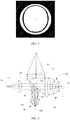
- the fluorescent wheel 2 when the fluorescent wheel 2 generates excited fluorescence, the light in the fluorescence having the same spectrum as the incident light will pass through the region and return along the original light path of the incident light. Therefore, after the fluorescence is focused by the condenser 5, the center of the light distribution will miss this fluorescence part. As shown in FIG. 2 , a light-missing region 6 appears in the center, thereby reducing the uniformity of the light output by the light source.
- the present disclosure provides a light source that optically supplements a light-missing region, so as to improve the uniformity of light output by a light source.
- an embodiment of the present disclosure provides a light source, including an excitation light source; an excited light supplying device; a partially coating film; and a light supplementing device;
- the excitation light source is configured to emit excitation light
- the excited light supplying device is configured to generate excited light under irradiation of the excitation light
- the partially coating film is located on a light path of the excitation light and a light path of the excited light
- the partially coating film includes a first area and a second area
- the first area is configured to transmit/reflect an amount of the excitation light to form a main path light and reflect/transmit another amount of the excitation light to form a side path light
- the second area is configured to reflect/transmit all incident light
- the excited light supplying device is located on a light path of the main path light and deviates from a light path of the side path light
- the excited light supplying device is configured to generate the excited light propagating toward the partially coating film after being excited by the main path light
- the light supplementing device is
- an embodiment of the present disclosure provides a projection system including the abovementioned light source.
- the technical solution of the present disclosure uses the side path light to form a uniform light and returns this uniform light to the partially coating film. After passing through the first area of the partially coating film, this uniform light is combined with the excited light, and the missing light part in the excited light having the same spectrum as the excitation light is supplemented, thereby improving the uniformity of the light output by the light source.
- an excitation light is transmitted to an excited light supplying device through a partially coating film.
- the partially coating film generally includes two areas, i.e., a first area and a second area.
- the excitation light is transmitted through the first area of the partially coating film and then reaches the excited light supplying device, and in other embodiments, the excitation light is reflected by the first area of the partially coating film and then reaches the excited light supplying device.
- the transmission/reflection of the partially coating film to the excitation light is difficult to achieve 100%.
- the inventor of the present disclosure noticed this, and realizes that the excitation light is split into two paths of light after the partially coating film, which are defined as a main path light and a side path light, respectively.
- the main path light is the most of the excitation light transmitted or reflected to the excited light supplying device after passing through the partially coating film.
- the side path light is the small amount of the excitation light that is missing and does not reach the excited light supplying device after passing through the partially coating film, and this small amount of light is often reflected/transmitted by the partially coating film toward a direction different from a direction of the main path light.
- the inventor of the present disclosure skillfully use the side path light to form a uniform light beam and return this light beam to the partially coating film. After transmission/reflection of the partially coating film, this light beam is combined with the excited light. In this way, the missing light part in the excited light having the same spectrum as the excitation light is supplemented, thereby improving the uniformity of the light output by the light source.
- a light source includes an excitation light source 10, a partially coating film 20, an excited light supplying device 30, a light concentrating component 40, and a light supplementing device 50.
- the excitation light source 10 is used to emit an excitation light 11.
- the excitation light source 10 is a laser light source or a laser diode light source that emits a laser light having a specific wavelength, such as blue light, or blue light plus red light. This laser light is used as the excitation light.
- the excitation light source may also use other types of light-emitting devices, such as an LED device, which will not be limited herein.
- the excited light supplying device 30 is used to supply an excited light.
- the excited light supplying device 30 includes a wavelength conversion device (such as the fluorescent wheel 31 in FIG. 3 ) and a light collecting system 32.
- the fluorescent wheel 31 is used to generate an excited light 33 under the irradiation of the excitation light.
- the fluorescent wave bands produced after excitation are also different, usually producing white light, or one or more primary colors.
- the excitation light 11 is blue light
- the fluorescent wheel 31 is coated with a yellow fluorescent powder. It should be understood that in other embodiments, the excitation light having other wavelength ranges can be adopted, and the fluorescent wheel coated with the fluorescent material having other luminescent characteristics can be used, which will not be limited to the technical solutions of the above embodiments.
- the excited light may propagate along a direction consistent with the incident direction of the excitation light, or may propagate along a direction opposite to the incident direction of the excitation light.
- the excited light generated by the reflective fluorescent wheel 31 provided in this embodiment propagates along a direction opposite to the incident direction of the excitation light, that is, the excited light propagates along a direction opposite to the incident path of the excitation light.
- the light collecting system 32 may be a lens group that is located on a light path where the excited light propagates, and the light collecting system 32 is used to collect and collimate the divergent fluorescence. The excited light is collimated by the light collecting system 32 and then reaches a side of the partially coating film 20.
- the wavelength conversion device may also be implemented in other manners, such as a non-fluorescent mode or non-wheel mode.
- the light collecting system may also be omitted in the excited light supplying device 30, that is, the excitation light generated by the wavelength conversion device is not processed by a light collecting system.
- the partially coating film 20 is located in the light path of the excitation light, and is also located in the light path of the excited light. In this embodiment, the partially coating film 20 is obliquely disposed between the excitation light source 10 and the excited light supplying device 30.
- the partially coating film 20 includes a first area 21 and a second area 22, as shown in FIG. 4 .
- the first area 21 is located at a center of the partially coating film 20, and the second area 22 is located at a periphery of the first area 21 and surrounds the first area 21.
- the first area 21 and the second area 22 may also have other positional relation depending on the specific design.
- the first area 21 is located in the light path of the excitation light 11 output by the excitation light source 10.
- the size and shape of the first area 21 is substantially the same as the size and shape of the light spot of the excitation light 11 reaching the partially coating film. Both the first area 21 and the second area 22 are located in the light path of the excited light 33.
- the first area 21 is for transmitting the excitation light to form a main path light and reflecting the excitation light to form a side path light.
- the first area 21 is equivalent to a filter having a predetermined wavelength, but the filter is not 100% transmissive. That is, when the light reaches the first area 21, most of the light having a wavelength matched up with the first area 21 is transmitted, and a small amount of the light is reflected.
- a main function of the first area 21 is to transmit the excitation light.
- the first area 21 is transmissive for blue light and reflective for yellow light, and when the excitation light is blue and red light, the first area 21 is transmissive for blue and red light and reflective for green light.
- the second area 22 is an area that reflects all the incident light. The total reflection means that the second area 22 is reflective for all incident light having any wavelength. In this embodiment, the second area 22 is reflective for all of the excitation light, the excited light, and the supplemental light generated by the light supplementing device 50.
- the first area 21 is located in the light path of the excitation light 11, and the size of the first area 21 is substantially the same as the size of the light spot of the incident excitation light 11, so theoretically, the excitation light 11 will totally pass through the first area 21 and then reach the fluorescent wheel 31.
- the transmittance of the first area 21 cannot reach 100%, so there is always some excitation light 11 failing to reach the fluorescent wheel 31 after passing through the first area 21, but being reflected and/or absorbed by the first area 21.
- the excitation light 11 is split into two paths of light after passing through the first area 21, such as a main path light 11a and a side path light 11b shown in FIG. 3 .
- the main path light 11a is most of the excitation light 11 passing through the first area 21, which propagates along a first direction (in this embodiment, a direction along which the excitation light 11 originally propagates) and reaches the fluorescent wheel 31.
- the side path light 11b is a small amount of the excitation light 11 reflected by the first area 21 and propagates in a second direction.
- the second direction is different from the first direction.
- the second direction is perpendicular to the first direction, so the side path light 11b cannot reach the fluorescent wheel 31.
- the side path light 11b is the missing light.
- both the first area 21 and the second area 22 are located in the light path of the excited light 33, when the excited light 33 reaches the first area 21 and the second area 22, the first area 21 is transmissive for the light of the excited light 33 having the same spectrum as the excitation light, and reflective for the other light of the excited light 33 having other spectrums.
- the second area 22 is reflective for light having any spectrum (including the excited light 33).
- the excited light 33 propagates along a third direction after being reflected.
- the third direction is different from the first direction.
- the third direction is perpendicular to the first direction and opposite to the second direction. After being reflected, the excited light 33 forms the output light of the light source after being concentrated by the light concentrating component 40 located in its propagation path.
- the output light composed only by the excited light misses part light having the same spectrum as the excitation light. As a result, the uniformity of the output light output is reduced.
- the light supplementing device 50 is located in the light path of the side path light 11b, and is used to generate supplemental light 51 (shown by an oblique line in the figure) after a uniform process to the side path light 11b (shown by a vertical line in the figure).
- the supplemental light 51 propagates along a direction opposite to the incident direction of the side path light 11b, and propagates along the third direction after passing through the first area 21 of the partially coating film and is combined with the reflected excited light 33, and this combined light serves as the light output by the light source. In this way, the missing light part in the excited light having the same spectrum as the excitation light is supplemented, thereby improving the uniformity of the light output by the light source.
- the light supplementing device 50 is a reflective scattering plate 50a, and the reflective scattering plate 50a is located in the light path of the side path light, and generates scattered light after being irradiated by the side path light, thereby converting the side path light into a uniform light plate or light group and thus achieving the purpose of light homogenization. Since the reflective scattering plate 50a also has a reflective function, the scattered light can be reflected back to the first area of the partially coating film, thereby forming decoherent supplemental light.
- the divergence angle of the supplemental light after passing through the partially coating film is consistent with the divergence angle of the excited light after passing through the partially coating film, so that the overall efficiency can be maximized.
- the coating of the first area 21 is transmissive for blue light and reflective for yellow light
- the supplemental light is blue light.
- the coating of the first area 21 is transmissive for red light and blue light and reflective for green light, so as to transmit the excitation light and filter out light having other bands
- the supplemental light is blue light plus red light.
- the red light has two parts, one part is the red light generated by the fluorescence being excited by blue light, and the other part is the red light directly collected from the scattering red light.
- the excitation light output by the excitation light source 10 is divided into two paths of light by the partially coating film, the main path light 11a reaches the fluorescent wheel 31, and the side path light 11b reaches the reflective scattering plate 50a.
- the fluorescent wheel 31 generates an excited light under the irradiation of the main path light 11a, and the excited light is collected and collimated by the light collecting system 32 and then reaches a side of the partially coating film 20 facing the excited light supplying device 30.
- the excited light that reaches the first area 21 For the excited light that reaches the first area 21, the light having the same wavelength as the excitation light passes through the diaphragm of the first area 21 and propagates along the original propagation path of the excitation light, and the light having a different wavelength from the excitation light is reflected by the diaphragm of the first area 21 and propagates along the third direction.
- the excited light that reaches the second area 22 is reflected by the diaphragm of the second area 22 and propagates along the third direction, but the center of the light output at this time misses the light having the same wavelength as the excitation light, as a result, the uniformity of the center of the light is reduced.
- the side path light 11b reaches the reflective scattering plate 50a, and is scattered and reflected by the reflective scattering plate 50a to form a path of light returning to the partially coating film 20.
- this path of light is referred to as supplemental light.
- the supplemental light that reaches the first area 21 the light having the same wavelength as the excitation light passes through the diaphragm of the first area 21 and propagates along the third direction, and is added to the center of the excited light reflected by the partially coating film 20, so as to supplement the light having the same wavelength as the excitation light at the center of the excited light, thereby increasing the uniformity of the light at the center of the excited light, as shown in FIG. 5 . It can be seen by comparing FIG. 2 with FIG. 5 that, the uniformity of the center of the output light is improved.
- the supplemental light that reaches the second area 22 is lost by reflection of the second area 22.
- the light supplementing device 50 includes a Lambert scattering plate 50b and a light collecting system 50c.
- the Lambert scattering plate 50b is located in the light path of the side path light, and generates scattered light after being irradiated by the side path light 11b. The scattered light is concentrated by the light collecting system 50c and then reaches the first area 21 of the partially coating film 20 to form the supplemental light 51.
- the Lambert scattering plate can also be replaced with a white fluorescent plate.
- the white fluorescent plate is a fluorescent plate capable of absorbing the excitation light and generating white light.
- the white fluorescent plate generates white light after being irradiated by the side path light, and the white light is concentrated by the light collecting system and then reaches the first area of the partially coating film to form the supplemental light.
- the overall efficiency of the light source can be maximized.
- the first area 21 shown in FIG. 4 may also has the main function of reflecting the excitation light, and the reflectivity is not 100%. That is, the excitation light reflected by the first area 21 is formed as the main path light, and the excitation light passing through the first area 21 is formed as a side path light.
- the second area 22 is used to transmit all the incident light.
- the total transmission means that light having any wavelength can pass through the second area 22.
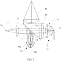
- the excitation light 11 is reflected by the first area 21 to form the main path light 11a, and passes through the first area 21 to form the side path light 11b.
- a propagation direction of the side path light 11b is perpendicular to a propagation direction of the main path light 11a.
- the fluorescent wheel 31 is excited by the main path light 11a to generate excited light 33.
- the excited light 33 reaches the partially coating film 20, the excited light 33 passes through the partially coating film 20 and propagates along a third direction.
- the third direction is opposite to the first direction and perpendicular to the second direction.
- the excited light is white light or monochromatic light or composite light having the same wavelength as the excitation light, and the excited light after being supplemented and concentrated reaches the spatial light modulator.
- the spatial light modulator may be a mono-piece light modulator or a multi-piece light modulator.
- the light output by the light source may also be a multi-primary sequence light
- the spatial light modulator is also a multi-piece (e.g., three-piece) light modulator.
- the fluorescent wheel can be changed to a multi-segment structure, for example, the fluorescent wheel is a three-stage structure, which is respectively excited to generate red light, green light, and blue light.
- the incident excitation light is blue light
- the supplement blue light is always generated but only works in the blue segment.
- a light valve synchronized with the fluorescent wheel may be provided between the partially coating film and the light supplementing device, when the fluorescent wheel outputs blue light, the light valve is opened to supplement the blue light; when the fluorescent wheel outputs red light and green light, the light valve is closed to prevent the supplement blue light from interfering the excited light through the partially coating film.
- the incident excitation light is blue light plus red light
- the supplement blue light is always generated and only works in the blue segment, and the supplement red light can be always generated or can be generated only in the red segment, if the red light is generated only in the red segment, the service life of the red light can be improved.
Landscapes
- Physics & Mathematics (AREA)
- General Physics & Mathematics (AREA)
- Engineering & Computer Science (AREA)
- Multimedia (AREA)
- Optics & Photonics (AREA)
- Projection Apparatus (AREA)
- Investigating, Analyzing Materials By Fluorescence Or Luminescence (AREA)
Abstract
Description
- The present disclosure relates to the field of projection display, and in particular, to a light source and a projection system.
-
FIG. 1 shows a structure of a light source for projection or illumination in the prior art. As shown inFIG. 1 , a partially coatingfilm 4 is arranged between a laser generator 1 and a fluorescent wheel 2. The partially coatingfilm 4 includes two regions, i.e., a transmissive region and a reflective region. The laser light is incident to the fluorescent wheel 2 after passing through the partially coatingfilm 4 from left to right. The generated fluorescence is collected by a lens group 3, reflected by the partially coatingfilm 4, concentrated by acondenser 5, and then supplied to a light modulator (not shown), so that the light signal can be modulated according to display data. In order to maximize efficiency, the region of the partially coatingfilm 4 where laser light can pass through has substantially the same size as a size of the incident light spot. - However, when the fluorescent wheel 2 generates excited fluorescence, the light in the fluorescence having the same spectrum as the incident light will pass through the region and return along the original light path of the incident light. Therefore, after the fluorescence is focused by the
condenser 5, the center of the light distribution will miss this fluorescence part. As shown inFIG. 2 , a light-missing region 6 appears in the center, thereby reducing the uniformity of the light output by the light source. - The present disclosure provides a light source that optically supplements a light-missing region, so as to improve the uniformity of light output by a light source.
- According to a first aspect, an embodiment of the present disclosure provides a light source, including an excitation light source; an excited light supplying device; a partially coating film; and a light supplementing device;
the excitation light source is configured to emit excitation light,
the excited light supplying device is configured to generate excited light under irradiation of the excitation light,
the partially coating film is located on a light path of the excitation light and a light path of the excited light, the partially coating film includes a first area and a second area, the first area is configured to transmit/reflect an amount of the excitation light to form a main path light and reflect/transmit another amount of the excitation light to form a side path light, the second area is configured to reflect/transmit all incident light, the excited light supplying device is located on a light path of the main path light and deviates from a light path of the side path light, and the excited light supplying device is configured to generate the excited light propagating toward the partially coating film after being excited by the main path light,
the light supplementing device is located on the light path of the side path light and configured to perform light homogenization to the side path light and generate supplemental light propagated to the partially coating film and the supplemental light is combined with the excited light after passing through the first area of the partially coating film. - According to a second aspect, an embodiment of the present disclosure provides a projection system including the abovementioned light source.
- The technical solution of the present disclosure uses the side path light to form a uniform light and returns this uniform light to the partially coating film. After passing through the first area of the partially coating film, this uniform light is combined with the excited light, and the missing light part in the excited light having the same spectrum as the excitation light is supplemented, thereby improving the uniformity of the light output by the light source.
-
-
FIG. 1 is a schematic diagram of a light reflection structure in the prior art; -
FIG. 2 is a light distribution diagram in the prior art; -
FIG. 3 is a schematic diagram of a light reflection structure using a reflective scattering light sheet; -
FIG. 4 is a schematic diagram of a partially coating film; -
FIG. 5 is a light distribution diagram according to the present disclosure; -
FIG. 6 is a schematic diagram of a light reflection structure using a Lambert scattering plate; and -
FIG. 7 is a schematic diagram of a light reflection structure using a different partially coating film. - In an embodiment of the present disclosure, an excitation light is transmitted to an excited light supplying device through a partially coating film. The partially coating film generally includes two areas, i.e., a first area and a second area. In some embodiments, the excitation light is transmitted through the first area of the partially coating film and then reaches the excited light supplying device, and in other embodiments, the excitation light is reflected by the first area of the partially coating film and then reaches the excited light supplying device. In practice, regardless of whether the excitation light is transmitted or reflected to the excited light supplying device, the transmission/reflection of the partially coating film to the excitation light is difficult to achieve 100%. Most of the excitation light is transmitted or reflected to the excited light supplying device after the transmission/reflection of the partially coating film, while a small amount of the excitation light is missing after the transmission/reflection of the partially coating film. The inventor of the present disclosure noticed this, and realizes that the excitation light is split into two paths of light after the partially coating film, which are defined as a main path light and a side path light, respectively. The main path light is the most of the excitation light transmitted or reflected to the excited light supplying device after passing through the partially coating film. The side path light is the small amount of the excitation light that is missing and does not reach the excited light supplying device after passing through the partially coating film, and this small amount of light is often reflected/transmitted by the partially coating film toward a direction different from a direction of the main path light. The inventor of the present disclosure skillfully use the side path light to form a uniform light beam and return this light beam to the partially coating film. After transmission/reflection of the partially coating film, this light beam is combined with the excited light. In this way, the missing light part in the excited light having the same spectrum as the excitation light is supplemented, thereby improving the uniformity of the light output by the light source.
- The present disclosure will be further described in the following with reference to the accompanying drawings and embodiments.
- With reference to
FIG. 3 , a light source includes anexcitation light source 10, a partially coatingfilm 20, an excitedlight supplying device 30, alight concentrating component 40, and alight supplementing device 50. - The
excitation light source 10 is used to emit anexcitation light 11. In this embodiment, theexcitation light source 10 is a laser light source or a laser diode light source that emits a laser light having a specific wavelength, such as blue light, or blue light plus red light. This laser light is used as the excitation light. In other embodiments, the excitation light source may also use other types of light-emitting devices, such as an LED device, which will not be limited herein. - The excited
light supplying device 30 is used to supply an excited light. In this embodiment, the excitedlight supplying device 30 includes a wavelength conversion device (such as thefluorescent wheel 31 inFIG. 3 ) and alight collecting system 32. Thefluorescent wheel 31 is used to generate anexcited light 33 under the irradiation of the excitation light. When the materials applied on thefluorescent wheel 31 are different, the fluorescent wave bands produced after excitation are also different, usually producing white light, or one or more primary colors. In this embodiment, theexcitation light 11 is blue light, and thefluorescent wheel 31 is coated with a yellow fluorescent powder. It should be understood that in other embodiments, the excitation light having other wavelength ranges can be adopted, and the fluorescent wheel coated with the fluorescent material having other luminescent characteristics can be used, which will not be limited to the technical solutions of the above embodiments. - The excited light may propagate along a direction consistent with the incident direction of the excitation light, or may propagate along a direction opposite to the incident direction of the excitation light. The excited light generated by the reflective
fluorescent wheel 31 provided in this embodiment propagates along a direction opposite to the incident direction of the excitation light, that is, the excited light propagates along a direction opposite to the incident path of the excitation light. Thelight collecting system 32 may be a lens group that is located on a light path where the excited light propagates, and thelight collecting system 32 is used to collect and collimate the divergent fluorescence. The excited light is collimated by thelight collecting system 32 and then reaches a side of the partially coatingfilm 20. In other embodiments, the wavelength conversion device may also be implemented in other manners, such as a non-fluorescent mode or non-wheel mode. The light collecting system may also be omitted in the excitedlight supplying device 30, that is, the excitation light generated by the wavelength conversion device is not processed by a light collecting system. Such a solution is not within the scope of the present disclosure, but is included in the concept of the present disclosure. - The partially coating
film 20 is located in the light path of the excitation light, and is also located in the light path of the excited light. In this embodiment, the partially coatingfilm 20 is obliquely disposed between theexcitation light source 10 and the excitedlight supplying device 30. The partially coatingfilm 20 includes afirst area 21 and asecond area 22, as shown inFIG. 4 . Generally, thefirst area 21 is located at a center of the partially coatingfilm 20, and thesecond area 22 is located at a periphery of thefirst area 21 and surrounds thefirst area 21. In other embodiments, thefirst area 21 and thesecond area 22 may also have other positional relation depending on the specific design. Thefirst area 21 is located in the light path of theexcitation light 11 output by theexcitation light source 10. For maximum efficiency, the size and shape of thefirst area 21 is substantially the same as the size and shape of the light spot of theexcitation light 11 reaching the partially coating film. Both thefirst area 21 and thesecond area 22 are located in the light path of theexcited light 33. In this embodiment, thefirst area 21 is for transmitting the excitation light to form a main path light and reflecting the excitation light to form a side path light. In practice, thefirst area 21 is equivalent to a filter having a predetermined wavelength, but the filter is not 100% transmissive. That is, when the light reaches thefirst area 21, most of the light having a wavelength matched up with thefirst area 21 is transmitted, and a small amount of the light is reflected. In this embodiment, a main function of thefirst area 21 is to transmit the excitation light. Therefore, when the excitation light is blue light, thefirst area 21 is transmissive for blue light and reflective for yellow light, and when the excitation light is blue and red light, thefirst area 21 is transmissive for blue and red light and reflective for green light. When the main function of thefirst area 21 is to transmit the excitation light, thesecond area 22 is an area that reflects all the incident light. The total reflection means that thesecond area 22 is reflective for all incident light having any wavelength. In this embodiment, thesecond area 22 is reflective for all of the excitation light, the excited light, and the supplemental light generated by thelight supplementing device 50. - In this embodiment, the
first area 21 is located in the light path of theexcitation light 11, and the size of thefirst area 21 is substantially the same as the size of the light spot of theincident excitation light 11, so theoretically, theexcitation light 11 will totally pass through thefirst area 21 and then reach thefluorescent wheel 31. However, in practice, due to manufacturing process limitations, the transmittance of thefirst area 21 cannot reach 100%, so there is always someexcitation light 11 failing to reach thefluorescent wheel 31 after passing through thefirst area 21, but being reflected and/or absorbed by thefirst area 21. In this case, theexcitation light 11 is split into two paths of light after passing through thefirst area 21, such as a main path light 11a and a side path light 11b shown inFIG. 3 . Herein, the main path light 11a is most of theexcitation light 11 passing through thefirst area 21, which propagates along a first direction (in this embodiment, a direction along which theexcitation light 11 originally propagates) and reaches thefluorescent wheel 31. The side path light 11b is a small amount of theexcitation light 11 reflected by thefirst area 21 and propagates in a second direction. Herein, the second direction is different from the first direction. In this embodiment, the second direction is perpendicular to the first direction, so the side path light 11b cannot reach thefluorescent wheel 31. For thefluorescent wheel 31, the side path light 11b is the missing light. - Since both the
first area 21 and thesecond area 22 are located in the light path of theexcited light 33, when theexcited light 33 reaches thefirst area 21 and thesecond area 22, thefirst area 21 is transmissive for the light of theexcited light 33 having the same spectrum as the excitation light, and reflective for the other light of theexcited light 33 having other spectrums. Thesecond area 22 is reflective for light having any spectrum (including the excited light 33). Theexcited light 33 propagates along a third direction after being reflected. Herein, the third direction is different from the first direction. In this embodiment, the third direction is perpendicular to the first direction and opposite to the second direction. After being reflected, the excited light 33 forms the output light of the light source after being concentrated by thelight concentrating component 40 located in its propagation path. However, since the light of the excited light having the same spectrum as the excitation light passes through thefirst area 21, the output light composed only by the excited light misses part light having the same spectrum as the excitation light. As a result, the uniformity of the output light output is reduced. - The light supplementing
device 50 is located in the light path of the side path light 11b, and is used to generate supplemental light 51 (shown by an oblique line in the figure) after a uniform process to the side path light 11b (shown by a vertical line in the figure). Thesupplemental light 51 propagates along a direction opposite to the incident direction of the side path light 11b, and propagates along the third direction after passing through thefirst area 21 of the partially coating film and is combined with the reflectedexcited light 33, and this combined light serves as the light output by the light source. In this way, the missing light part in the excited light having the same spectrum as the excitation light is supplemented, thereby improving the uniformity of the light output by the light source. In this embodiment, thelight supplementing device 50 is areflective scattering plate 50a, and thereflective scattering plate 50a is located in the light path of the side path light, and generates scattered light after being irradiated by the side path light, thereby converting the side path light into a uniform light plate or light group and thus achieving the purpose of light homogenization. Since thereflective scattering plate 50a also has a reflective function, the scattered light can be reflected back to the first area of the partially coating film, thereby forming decoherent supplemental light. By adjusting a scattering angle of the reflective scattering plate and adjusting a spacing between the reflective scattering plate and the partially coating film, the divergence angle of the supplemental light after passing through the partially coating film is consistent with the divergence angle of the excited light after passing through the partially coating film, so that the overall efficiency can be maximized. - When the excitation light is blue light, the coating of the
first area 21 is transmissive for blue light and reflective for yellow light, and the supplemental light is blue light. When the excitation light is blue light plus red light, the coating of thefirst area 21 is transmissive for red light and blue light and reflective for green light, so as to transmit the excitation light and filter out light having other bands, and the supplemental light is blue light plus red light. The red light has two parts, one part is the red light generated by the fluorescence being excited by blue light, and the other part is the red light directly collected from the scattering red light. By selecting the transmittance or size of the first area of the partially coating film, it is possible to control the amount of light reflected onto the light supplementing device, thereby controlling the amount of supplemental light. - The light path processing process of this embodiment will be described in the following with reference to
FIG. 3 . - The excitation light output by the
excitation light source 10 is divided into two paths of light by the partially coating film, the main path light 11a reaches thefluorescent wheel 31, and the side path light 11b reaches thereflective scattering plate 50a. Thefluorescent wheel 31 generates an excited light under the irradiation of the main path light 11a, and the excited light is collected and collimated by thelight collecting system 32 and then reaches a side of the partially coatingfilm 20 facing the excitedlight supplying device 30. For the excited light that reaches thefirst area 21, the light having the same wavelength as the excitation light passes through the diaphragm of thefirst area 21 and propagates along the original propagation path of the excitation light, and the light having a different wavelength from the excitation light is reflected by the diaphragm of thefirst area 21 and propagates along the third direction. The excited light that reaches thesecond area 22 is reflected by the diaphragm of thesecond area 22 and propagates along the third direction, but the center of the light output at this time misses the light having the same wavelength as the excitation light, as a result, the uniformity of the center of the light is reduced. At the same time, the side path light 11b reaches thereflective scattering plate 50a, and is scattered and reflected by thereflective scattering plate 50a to form a path of light returning to the partially coatingfilm 20. Herein, this path of light is referred to as supplemental light. For the supplemental light that reaches thefirst area 21, the light having the same wavelength as the excitation light passes through the diaphragm of thefirst area 21 and propagates along the third direction, and is added to the center of the excited light reflected by the partially coatingfilm 20, so as to supplement the light having the same wavelength as the excitation light at the center of the excited light, thereby increasing the uniformity of the light at the center of the excited light, as shown inFIG. 5 . It can be seen by comparingFIG. 2 withFIG. 5 that, the uniformity of the center of the output light is improved. The supplemental light that reaches thesecond area 22 is lost by reflection of thesecond area 22. - This embodiment differs from the first embodiment in the light supplementing device. With reference to
FIG. 6 , thelight supplementing device 50 includes aLambert scattering plate 50b and alight collecting system 50c. TheLambert scattering plate 50b is located in the light path of the side path light, and generates scattered light after being irradiated by the side path light 11b. The scattered light is concentrated by thelight collecting system 50c and then reaches thefirst area 21 of the partially coatingfilm 20 to form thesupplemental light 51. - In this embodiment, the Lambert scattering plate can also be replaced with a white fluorescent plate. Herein, the white fluorescent plate is a fluorescent plate capable of absorbing the excitation light and generating white light. The white fluorescent plate generates white light after being irradiated by the side path light, and the white light is concentrated by the light collecting system and then reaches the first area of the partially coating film to form the supplemental light.
- In this embodiment, by controlling the diameter of the light collecting system to be consistent with the size of the first area, the overall efficiency of the light source can be maximized.
- This embodiment differs from the first embodiment and the second embodiment in the partially coating film. The
first area 21 shown inFIG. 4 may also has the main function of reflecting the excitation light, and the reflectivity is not 100%. That is, the excitation light reflected by thefirst area 21 is formed as the main path light, and the excitation light passing through thefirst area 21 is formed as a side path light. Thesecond area 22 is used to transmit all the incident light. Herein, the total transmission means that light having any wavelength can pass through thesecond area 22. With such a partially coating film, the reflectivity of thefirst area 21 is less than 100%, so that most of theexcitation light 11a is reflected, and a small amount of theexcitation light 11a passes through thefirst area 21. With reference toFIG. 7 , theexcitation light 11 is reflected by thefirst area 21 to form the main path light 11a, and passes through thefirst area 21 to form the side path light 11b. A propagation direction of the side path light 11b is perpendicular to a propagation direction of the main path light 11a. Thefluorescent wheel 31 is excited by the main path light 11a to generateexcited light 33. When theexcited light 33 reaches the partially coatingfilm 20, the excited light 33 passes through the partially coatingfilm 20 and propagates along a third direction. Herein, the third direction is opposite to the first direction and perpendicular to the second direction. - In the above embodiments, the excited light is white light or monochromatic light or composite light having the same wavelength as the excitation light, and the excited light after being supplemented and concentrated reaches the spatial light modulator. Herein, the spatial light modulator may be a mono-piece light modulator or a multi-piece light modulator. In other embodiments, the light output by the light source may also be a multi-primary sequence light, and the spatial light modulator is also a multi-piece (e.g., three-piece) light modulator. When the output light is a multi-primary sequence light, the fluorescent wheel can be changed to a multi-segment structure, for example, the fluorescent wheel is a three-stage structure, which is respectively excited to generate red light, green light, and blue light. If the incident excitation light is blue light, the supplement blue light is always generated but only works in the blue segment. For example, a light valve synchronized with the fluorescent wheel may be provided between the partially coating film and the light supplementing device, when the fluorescent wheel outputs blue light, the light valve is opened to supplement the blue light; when the fluorescent wheel outputs red light and green light, the light valve is closed to prevent the supplement blue light from interfering the excited light through the partially coating film. If the incident excitation light is blue light plus red light, the supplement blue light is always generated and only works in the blue segment, and the supplement red light can be always generated or can be generated only in the red segment, if the red light is generated only in the red segment, the service life of the red light can be improved.
- The present disclosure has been described above with reference to specific examples, which are merely used to illustrate the present disclosure and are not intended to limit the present disclosure. Those skilled in the art can make simple derivations, variations or substitutions based on the concept of the present disclosure.
Claims (11)
- A light source, comprising:an excitation light source;an excited light supplying device;a partially coating film; anda light supplementing device;wherein the excitation light source is configured to emit excitation light,the excited light supplying device is configured to generate excited light under irradiation of the excitation light,the partially coating film is located in a light path of the excitation light and a light path of the excited light, the partially coating film comprises a first area and a second area, the first area is configured to transmit an amount of the excitation light to form a main path light and reflect another amount of the excitation light to form a side path light, the second area is configured to reflect all incident light, the excited light supplying device is located in a light path of the main path light and deviates from a light path of the side path light, and the excited light supplying device is configured to generate the excited light propagating toward the partially coating film after being excited by the main path light,the light supplementing device is located in the light path of the side path light and configured to perform light homogenization to the side path light and generate supplemental light propagated to the partially coating film, and the supplemental light is combined with the excited light after passing through the first area of the partially coating film.
- A light source, comprising:an excitation light source;an excited light supplying device;a partially coating film; anda light supplementing device;wherein the excitation light source is configured to emit excitation light, the excited light supplying device is configured to generate excited light under irradiation of the excitation light, the partially coating film is located in a light path of the excitation light and a light path of the excited light, the partially coating film comprises a first area and a second area, the first area is configured to reflect an amount of the excitation light to form a main path light and transmit another amount of the excitation light to form a side path light, the second area is configured to transmit all incident light, the excited light supplying device is located on a light path of the main path light and deviates from a light path of the side path light, and the excited light supplying device is configured to generate the excited light propagating toward the partially coating film after being excited by the main path light, the light supplementing device is located in the light path of the side path light and configured to perform light homogenization to the side path light and generate supplemental light propagated to the partially coating film, and the supplemental light is combined with the excited light after passing through the first area of the partially coating film.
- The light source according to claim 1 or 2, wherein the light supplementing device is a reflective scattering plate, and the reflective scattering plate is located in the light path of the side path light, and is configured to generate scattered light after being irradiated by the side path light, and reflects the scattered light back to the first area of the partially coating film to form the supplemental light.
- The light source according to claim 3, wherein a scattering angle of the reflective scattering plate and a spacing between the reflective scattering plate and the partially coating film are adjusted to enable a divergence angle of the supplemental light after passing through the partially coating film to be consistent with a divergence angle of the excited light after passing through the partially coating film.
- The light source according to claim 3, wherein the supplemental light generated by the reflective scattering plate is decoherent light.
- The light source according to claim 1 or 2, wherein the light supplementing device comprises a Lambert scattering plate and a light collecting system, the Lambert scattering plate is located in the light path of the side path light, and is configured to generate scattered light after being irradiated by the side path light, and the scattered light is concentrated by the light collecting system and then incident to the first area of the partially coating film to form the supplemental light.
- The light source according to claim 1 or 2, wherein the light supplementing device comprises a white fluorescent plate and a light collecting system, and the white fluorescent plate is located in the light path of the side path light, and is configured to generate white light after being irradiated by the side path light, and the white light is concentrated by the light collecting system and then incident to the first area of the partially coating film to form the supplemental light.
- The light source according to claim 6 or claim 7, wherein the light collecting system has an aperture in consistent with a size of the first area.
- The light source according to claim 1 or 2, wherein a shape and a size of the first area are consistent with a shape and a size of a light spot of the excitation light incident to the partially coating film.
- The light source according to claim 1 or 2, wherein the second area is located at a periphery of the first area and surrounds the first area, the main path light propagates along a first direction, the side path light propagates along a second direction, and the excited light forms an excited light propagating along a third direction after passing through the first area and the second area, wherein the first direction, the second direction, and the third direction are different directions.
- A projection system, comprising the light source according to any of claims 1-10.
Applications Claiming Priority (2)
| Application Number | Priority Date | Filing Date | Title |
|---|---|---|---|
| CN201610518166.1A CN107561836B (en) | 2016-07-01 | 2016-07-01 | A kind of light source and optical projection system |
| PCT/CN2017/081419 WO2018000920A1 (en) | 2016-07-01 | 2017-04-21 | Light source and projection system |
Publications (3)
| Publication Number | Publication Date |
|---|---|
| EP3480655A1 true EP3480655A1 (en) | 2019-05-08 |
| EP3480655A4 EP3480655A4 (en) | 2020-01-01 |
| EP3480655B1 EP3480655B1 (en) | 2024-10-30 |
Family
ID=60785248
Family Applications (1)
| Application Number | Title | Priority Date | Filing Date |
|---|---|---|---|
| EP17818917.1A Active EP3480655B1 (en) | 2016-07-01 | 2017-04-21 | Light source and projection system |
Country Status (5)
| Country | Link |
|---|---|
| US (1) | US10824066B2 (en) |
| EP (1) | EP3480655B1 (en) |
| JP (1) | JP6741380B2 (en) |
| CN (1) | CN107561836B (en) |
| WO (1) | WO2018000920A1 (en) |
Families Citing this family (4)
| Publication number | Priority date | Publication date | Assignee | Title |
|---|---|---|---|---|
| CN107688274A (en) * | 2016-08-05 | 2018-02-13 | 深圳市光峰光电技术有限公司 | A kind of light supply apparatus and projector equipment |
| CN110347009A (en) * | 2019-06-13 | 2019-10-18 | 广州光联电子科技有限公司 | A kind of optical system of laser light source |
| CN114987355B (en) * | 2022-05-16 | 2024-11-12 | 中国第一汽车股份有限公司 | A vehicle logo suspension display device |
| CN121184771A (en) * | 2024-06-14 | 2025-12-23 | 深圳光峰科技股份有限公司 | Light source device and optical system |
Family Cites Families (15)
| Publication number | Priority date | Publication date | Assignee | Title |
|---|---|---|---|---|
| CN2826474Y (en) | 2005-08-26 | 2006-10-11 | 联诚光电股份有限公司 | Reflective single crystal silicon liquid crystal panel and projection device using the liquid crystal panel |
| JP5842162B2 (en) * | 2011-03-23 | 2016-01-13 | パナソニックIpマネジメント株式会社 | Light source device and image display device using the same |
| CN103913936B (en) * | 2012-12-28 | 2016-12-07 | 深圳市绎立锐光科技开发有限公司 | Lighting device and projection system |
| CN104020633B (en) | 2013-02-28 | 2015-12-09 | 深圳市绎立锐光科技开发有限公司 | Lighting device and related projection system |
| DE102013224768B4 (en) * | 2013-12-03 | 2023-07-27 | Coretronic Corporation | Light module for a projection device and DLP projector |
| JP2015163947A (en) * | 2014-02-03 | 2015-09-10 | キヤノン株式会社 | Light source optical system, light source device having the same, and image display device |
| CN204028554U (en) * | 2014-07-28 | 2014-12-17 | 深圳市绎立锐光科技开发有限公司 | Light-emitting device and optical projection system |
| CN105319819B (en) | 2014-07-28 | 2019-09-20 | 深圳光峰科技股份有限公司 | Lighting device and projection system |
| CN204593250U (en) * | 2015-04-29 | 2015-08-26 | 深圳市光峰光电技术有限公司 | A kind of light guide member and light supply apparatus |
| CN204986566U (en) * | 2015-09-23 | 2016-01-20 | 深圳市绎立锐光科技开发有限公司 | Illuminating device |
| CN205353549U (en) * | 2016-01-07 | 2016-06-29 | 深圳市绎立锐光科技开发有限公司 | Light source device and lighting device |
| CN106200235B (en) * | 2016-07-22 | 2019-01-25 | 明基智能科技(上海)有限公司 | Projector and the projecting method for applying it |
| CN108761981B (en) * | 2018-04-28 | 2020-10-20 | 苏州佳世达光电有限公司 | Projector with a light source |
| CN208188567U (en) * | 2018-05-17 | 2018-12-04 | 中强光电股份有限公司 | Lighting system and projection device |
| CN110632814A (en) * | 2018-06-25 | 2019-12-31 | 中强光电股份有限公司 | Lighting system and projection device |
-
2016
- 2016-07-01 CN CN201610518166.1A patent/CN107561836B/en active Active
-
2017
- 2017-04-21 JP JP2018568700A patent/JP6741380B2/en active Active
- 2017-04-21 EP EP17818917.1A patent/EP3480655B1/en active Active
- 2017-04-21 US US16/314,338 patent/US10824066B2/en active Active
- 2017-04-21 WO PCT/CN2017/081419 patent/WO2018000920A1/en not_active Ceased
Also Published As
| Publication number | Publication date |
|---|---|
| EP3480655A4 (en) | 2020-01-01 |
| WO2018000920A1 (en) | 2018-01-04 |
| US10824066B2 (en) | 2020-11-03 |
| CN107561836A (en) | 2018-01-09 |
| JP6741380B2 (en) | 2020-08-19 |
| JP2019521392A (en) | 2019-07-25 |
| US20200201152A1 (en) | 2020-06-25 |
| CN107561836B (en) | 2019-10-25 |
| EP3480655B1 (en) | 2024-10-30 |
Similar Documents
| Publication | Publication Date | Title |
|---|---|---|
| CN205982969U (en) | Light source device and projecting system | |
| US9897899B2 (en) | Light-emitting device and projection system | |
| CN205992115U (en) | Light-source system and projector equipment | |
| JP6168611B2 (en) | Light source, photosynthesis device, and projection device with light source | |
| CN108008593B (en) | Light source system and display equipment | |
| US10824066B2 (en) | Light source and projection system | |
| CN105549313B (en) | A kind of fluorescent wheel and fluorescence converting system | |
| CN107703705A (en) | Light-source system and projector equipment | |
| CN102692799A (en) | Light source system | |
| EP3495884A1 (en) | Light source device and projection apparatus | |
| US11156908B2 (en) | Light source device and projection display system thereof for adjustment of white balance | |
| CN109031870B (en) | Fluorescence conversion system | |
| CN205507347U (en) | Light source module and projection equipment | |
| WO2018209722A1 (en) | Projection light source with enhanced light intensity and projection system thereof | |
| CN110471245A (en) | Light-source system, projection device and lighting apparatus | |
| WO2019200931A1 (en) | Light source apparatus and display device | |
| CN204986566U (en) | Illuminating device | |
| CN108107658A (en) | Light-source system, optical projection system and lighting device | |
| CN206671744U (en) | A kind of projection arrangement | |
| CN106950785B (en) | A light source device and lighting device | |
| WO2021197355A1 (en) | Light source system | |
| CN115803677A (en) | Light source assembly and projection equipment | |
| CN112628617A (en) | Refraction and reflection type laser light-emitting device | |
| CN207318919U (en) | Light-source system and optical projection system | |
| CN103631020A (en) | Light-emitting device, excited light-emitting device and a projection display device |
Legal Events
| Date | Code | Title | Description |
|---|---|---|---|
| STAA | Information on the status of an ep patent application or granted ep patent |
Free format text: STATUS: THE INTERNATIONAL PUBLICATION HAS BEEN MADE |
|
| PUAI | Public reference made under article 153(3) epc to a published international application that has entered the european phase |
Free format text: ORIGINAL CODE: 0009012 |
|
| STAA | Information on the status of an ep patent application or granted ep patent |
Free format text: STATUS: REQUEST FOR EXAMINATION WAS MADE |
|
| 17P | Request for examination filed |
Effective date: 20190115 |
|
| AK | Designated contracting states |
Kind code of ref document: A1 Designated state(s): AL AT BE BG CH CY CZ DE DK EE ES FI FR GB GR HR HU IE IS IT LI LT LU LV MC MK MT NL NO PL PT RO RS SE SI SK SM TR |
|
| AX | Request for extension of the european patent |
Extension state: BA ME |
|
| DAV | Request for validation of the european patent (deleted) | ||
| DAX | Request for extension of the european patent (deleted) | ||
| A4 | Supplementary search report drawn up and despatched |
Effective date: 20191203 |
|
| RIC1 | Information provided on ipc code assigned before grant |
Ipc: G03B 21/20 20060101AFI20191127BHEP |
|
| STAA | Information on the status of an ep patent application or granted ep patent |
Free format text: STATUS: EXAMINATION IS IN PROGRESS |
|
| 17Q | First examination report despatched |
Effective date: 20200918 |
|
| GRAP | Despatch of communication of intention to grant a patent |
Free format text: ORIGINAL CODE: EPIDOSNIGR1 |
|
| STAA | Information on the status of an ep patent application or granted ep patent |
Free format text: STATUS: GRANT OF PATENT IS INTENDED |
|
| INTG | Intention to grant announced |
Effective date: 20240807 |
|
| GRAS | Grant fee paid |
Free format text: ORIGINAL CODE: EPIDOSNIGR3 |
|
| GRAA | (expected) grant |
Free format text: ORIGINAL CODE: 0009210 |
|
| STAA | Information on the status of an ep patent application or granted ep patent |
Free format text: STATUS: THE PATENT HAS BEEN GRANTED |
|
| AK | Designated contracting states |
Kind code of ref document: B1 Designated state(s): AL AT BE BG CH CY CZ DE DK EE ES FI FR GB GR HR HU IE IS IT LI LT LU LV MC MK MT NL NO PL PT RO RS SE SI SK SM TR |
|
| REG | Reference to a national code |
Ref country code: GB Ref legal event code: FG4D |
|
| REG | Reference to a national code |
Ref country code: CH Ref legal event code: EP |
|
| REG | Reference to a national code |
Ref country code: IE Ref legal event code: FG4D |
|
| REG | Reference to a national code |
Ref country code: DE Ref legal event code: R096 Ref document number: 602017085807 Country of ref document: DE |
|
| REG | Reference to a national code |
Ref country code: LT Ref legal event code: MG9D |
|
| REG | Reference to a national code |
Ref country code: NL Ref legal event code: MP Effective date: 20241030 |
|
| PG25 | Lapsed in a contracting state [announced via postgrant information from national office to epo] |
Ref country code: IS Free format text: LAPSE BECAUSE OF FAILURE TO SUBMIT A TRANSLATION OF THE DESCRIPTION OR TO PAY THE FEE WITHIN THE PRESCRIBED TIME-LIMIT Effective date: 20250228 Ref country code: PT Free format text: LAPSE BECAUSE OF FAILURE TO SUBMIT A TRANSLATION OF THE DESCRIPTION OR TO PAY THE FEE WITHIN THE PRESCRIBED TIME-LIMIT Effective date: 20250228 Ref country code: HR Free format text: LAPSE BECAUSE OF FAILURE TO SUBMIT A TRANSLATION OF THE DESCRIPTION OR TO PAY THE FEE WITHIN THE PRESCRIBED TIME-LIMIT Effective date: 20241030 |
|
| PG25 | Lapsed in a contracting state [announced via postgrant information from national office to epo] |
Ref country code: FI Free format text: LAPSE BECAUSE OF FAILURE TO SUBMIT A TRANSLATION OF THE DESCRIPTION OR TO PAY THE FEE WITHIN THE PRESCRIBED TIME-LIMIT Effective date: 20241030 Ref country code: NL Free format text: LAPSE BECAUSE OF FAILURE TO SUBMIT A TRANSLATION OF THE DESCRIPTION OR TO PAY THE FEE WITHIN THE PRESCRIBED TIME-LIMIT Effective date: 20241030 |
|
| REG | Reference to a national code |
Ref country code: AT Ref legal event code: MK05 Ref document number: 1737473 Country of ref document: AT Kind code of ref document: T Effective date: 20241030 |
|
| PG25 | Lapsed in a contracting state [announced via postgrant information from national office to epo] |
Ref country code: BG Free format text: LAPSE BECAUSE OF FAILURE TO SUBMIT A TRANSLATION OF THE DESCRIPTION OR TO PAY THE FEE WITHIN THE PRESCRIBED TIME-LIMIT Effective date: 20241030 |
|
| PG25 | Lapsed in a contracting state [announced via postgrant information from national office to epo] |
Ref country code: ES Free format text: LAPSE BECAUSE OF FAILURE TO SUBMIT A TRANSLATION OF THE DESCRIPTION OR TO PAY THE FEE WITHIN THE PRESCRIBED TIME-LIMIT Effective date: 20241030 |
|
| PG25 | Lapsed in a contracting state [announced via postgrant information from national office to epo] |
Ref country code: NO Free format text: LAPSE BECAUSE OF FAILURE TO SUBMIT A TRANSLATION OF THE DESCRIPTION OR TO PAY THE FEE WITHIN THE PRESCRIBED TIME-LIMIT Effective date: 20250130 |
|
| PG25 | Lapsed in a contracting state [announced via postgrant information from national office to epo] |
Ref country code: LV Free format text: LAPSE BECAUSE OF FAILURE TO SUBMIT A TRANSLATION OF THE DESCRIPTION OR TO PAY THE FEE WITHIN THE PRESCRIBED TIME-LIMIT Effective date: 20241030 Ref country code: GR Free format text: LAPSE BECAUSE OF FAILURE TO SUBMIT A TRANSLATION OF THE DESCRIPTION OR TO PAY THE FEE WITHIN THE PRESCRIBED TIME-LIMIT Effective date: 20250131 Ref country code: AT Free format text: LAPSE BECAUSE OF FAILURE TO SUBMIT A TRANSLATION OF THE DESCRIPTION OR TO PAY THE FEE WITHIN THE PRESCRIBED TIME-LIMIT Effective date: 20241030 |
|
| PG25 | Lapsed in a contracting state [announced via postgrant information from national office to epo] |
Ref country code: PL Free format text: LAPSE BECAUSE OF FAILURE TO SUBMIT A TRANSLATION OF THE DESCRIPTION OR TO PAY THE FEE WITHIN THE PRESCRIBED TIME-LIMIT Effective date: 20241030 |
|
| PG25 | Lapsed in a contracting state [announced via postgrant information from national office to epo] |
Ref country code: RS Free format text: LAPSE BECAUSE OF FAILURE TO SUBMIT A TRANSLATION OF THE DESCRIPTION OR TO PAY THE FEE WITHIN THE PRESCRIBED TIME-LIMIT Effective date: 20250130 |
|
| PG25 | Lapsed in a contracting state [announced via postgrant information from national office to epo] |
Ref country code: SM Free format text: LAPSE BECAUSE OF FAILURE TO SUBMIT A TRANSLATION OF THE DESCRIPTION OR TO PAY THE FEE WITHIN THE PRESCRIBED TIME-LIMIT Effective date: 20241030 |
|
| PGFP | Annual fee paid to national office [announced via postgrant information from national office to epo] |
Ref country code: DE Payment date: 20250411 Year of fee payment: 9 |
|
| PG25 | Lapsed in a contracting state [announced via postgrant information from national office to epo] |
Ref country code: DK Free format text: LAPSE BECAUSE OF FAILURE TO SUBMIT A TRANSLATION OF THE DESCRIPTION OR TO PAY THE FEE WITHIN THE PRESCRIBED TIME-LIMIT Effective date: 20241030 |
|
| PGFP | Annual fee paid to national office [announced via postgrant information from national office to epo] |
Ref country code: GB Payment date: 20250417 Year of fee payment: 9 |
|
| PG25 | Lapsed in a contracting state [announced via postgrant information from national office to epo] |
Ref country code: EE Free format text: LAPSE BECAUSE OF FAILURE TO SUBMIT A TRANSLATION OF THE DESCRIPTION OR TO PAY THE FEE WITHIN THE PRESCRIBED TIME-LIMIT Effective date: 20241030 |
|
| PGFP | Annual fee paid to national office [announced via postgrant information from national office to epo] |
Ref country code: FR Payment date: 20250429 Year of fee payment: 9 |
|
| PG25 | Lapsed in a contracting state [announced via postgrant information from national office to epo] |
Ref country code: RO Free format text: LAPSE BECAUSE OF FAILURE TO SUBMIT A TRANSLATION OF THE DESCRIPTION OR TO PAY THE FEE WITHIN THE PRESCRIBED TIME-LIMIT Effective date: 20241030 |
|
| PG25 | Lapsed in a contracting state [announced via postgrant information from national office to epo] |
Ref country code: SK Free format text: LAPSE BECAUSE OF FAILURE TO SUBMIT A TRANSLATION OF THE DESCRIPTION OR TO PAY THE FEE WITHIN THE PRESCRIBED TIME-LIMIT Effective date: 20241030 |
|
| PG25 | Lapsed in a contracting state [announced via postgrant information from national office to epo] |
Ref country code: CZ Free format text: LAPSE BECAUSE OF FAILURE TO SUBMIT A TRANSLATION OF THE DESCRIPTION OR TO PAY THE FEE WITHIN THE PRESCRIBED TIME-LIMIT Effective date: 20241030 |
|
| PG25 | Lapsed in a contracting state [announced via postgrant information from national office to epo] |
Ref country code: IT Free format text: LAPSE BECAUSE OF FAILURE TO SUBMIT A TRANSLATION OF THE DESCRIPTION OR TO PAY THE FEE WITHIN THE PRESCRIBED TIME-LIMIT Effective date: 20241030 |
|
| REG | Reference to a national code |
Ref country code: DE Ref legal event code: R097 Ref document number: 602017085807 Country of ref document: DE |
|
| PLBE | No opposition filed within time limit |
Free format text: ORIGINAL CODE: 0009261 |
|
| STAA | Information on the status of an ep patent application or granted ep patent |
Free format text: STATUS: NO OPPOSITION FILED WITHIN TIME LIMIT |
|
| PG25 | Lapsed in a contracting state [announced via postgrant information from national office to epo] |
Ref country code: SE Free format text: LAPSE BECAUSE OF FAILURE TO SUBMIT A TRANSLATION OF THE DESCRIPTION OR TO PAY THE FEE WITHIN THE PRESCRIBED TIME-LIMIT Effective date: 20241030 |
|
| 26N | No opposition filed |
Effective date: 20250731 |
|
| REG | Reference to a national code |
Ref country code: CH Ref legal event code: H13 Free format text: ST27 STATUS EVENT CODE: U-0-0-H10-H13 (AS PROVIDED BY THE NATIONAL OFFICE) Effective date: 20251125 |
|
| PG25 | Lapsed in a contracting state [announced via postgrant information from national office to epo] |
Ref country code: LU Free format text: LAPSE BECAUSE OF NON-PAYMENT OF DUE FEES Effective date: 20250421 |
|
| PG25 | Lapsed in a contracting state [announced via postgrant information from national office to epo] |
Ref country code: MC Free format text: LAPSE BECAUSE OF FAILURE TO SUBMIT A TRANSLATION OF THE DESCRIPTION OR TO PAY THE FEE WITHIN THE PRESCRIBED TIME-LIMIT Effective date: 20241030 |
|
| REG | Reference to a national code |
Ref country code: BE Ref legal event code: MM Effective date: 20250430 |
|
| PG25 | Lapsed in a contracting state [announced via postgrant information from national office to epo] |
Ref country code: BE Free format text: LAPSE BECAUSE OF NON-PAYMENT OF DUE FEES Effective date: 20250430 |
|
| PG25 | Lapsed in a contracting state [announced via postgrant information from national office to epo] |
Ref country code: CH Free format text: LAPSE BECAUSE OF NON-PAYMENT OF DUE FEES Effective date: 20250430 |
|
| PG25 | Lapsed in a contracting state [announced via postgrant information from national office to epo] |
Ref country code: IE Free format text: LAPSE BECAUSE OF NON-PAYMENT OF DUE FEES Effective date: 20250421 |