EP3480629A1 - Road surface state determination method - Google Patents
Road surface state determination method Download PDFInfo
- Publication number
- EP3480629A1 EP3480629A1 EP17819733.1A EP17819733A EP3480629A1 EP 3480629 A1 EP3480629 A1 EP 3480629A1 EP 17819733 A EP17819733 A EP 17819733A EP 3480629 A1 EP3480629 A1 EP 3480629A1
- Authority
- EP
- European Patent Office
- Prior art keywords
- road surface
- tire
- feature vector
- driving force
- braking
- Prior art date
- Legal status (The legal status is an assumption and is not a legal conclusion. Google has not performed a legal analysis and makes no representation as to the accuracy of the status listed.)
- Granted
Links
Images





Classifications
-
- B—PERFORMING OPERATIONS; TRANSPORTING
- B60—VEHICLES IN GENERAL
- B60C—VEHICLE TYRES; TYRE INFLATION; TYRE CHANGING; CONNECTING VALVES TO INFLATABLE ELASTIC BODIES IN GENERAL; DEVICES OR ARRANGEMENTS RELATED TO TYRES
- B60C23/00—Devices for measuring, signalling, controlling, or distributing tyre pressure or temperature, specially adapted for mounting on vehicles; Arrangement of tyre inflating devices on vehicles, e.g. of pumps or of tanks; Tyre cooling arrangements
- B60C23/02—Signalling devices actuated by tyre pressure
- B60C23/04—Signalling devices actuated by tyre pressure mounted on the wheel or tyre
- B60C23/0486—Signalling devices actuated by tyre pressure mounted on the wheel or tyre comprising additional sensors in the wheel or tyre mounted monitoring device, e.g. movement sensors, microphones or earth magnetic field sensors
- B60C23/0488—Movement sensor, e.g. for sensing angular speed, acceleration or centripetal force
-
- B—PERFORMING OPERATIONS; TRANSPORTING
- B60—VEHICLES IN GENERAL
- B60C—VEHICLE TYRES; TYRE INFLATION; TYRE CHANGING; CONNECTING VALVES TO INFLATABLE ELASTIC BODIES IN GENERAL; DEVICES OR ARRANGEMENTS RELATED TO TYRES
- B60C19/00—Tyre parts or constructions not otherwise provided for
-
- G—PHYSICS
- G06—COMPUTING OR CALCULATING; COUNTING
- G06F—ELECTRIC DIGITAL DATA PROCESSING
- G06F30/00—Computer-aided design [CAD]
- G06F30/20—Design optimisation, verification or simulation
- G06F30/27—Design optimisation, verification or simulation using machine learning, e.g. artificial intelligence, neural networks, support vector machines [SVM] or training a model
-
- B—PERFORMING OPERATIONS; TRANSPORTING
- B60—VEHICLES IN GENERAL
- B60C—VEHICLE TYRES; TYRE INFLATION; TYRE CHANGING; CONNECTING VALVES TO INFLATABLE ELASTIC BODIES IN GENERAL; DEVICES OR ARRANGEMENTS RELATED TO TYRES
- B60C23/00—Devices for measuring, signalling, controlling, or distributing tyre pressure or temperature, specially adapted for mounting on vehicles; Arrangement of tyre inflating devices on vehicles, e.g. of pumps or of tanks; Tyre cooling arrangements
- B60C23/06—Signalling devices actuated by deformation of the tyre, e.g. tyre mounted deformation sensors or indirect determination of tyre deformation based on wheel speed, wheel-centre to ground distance or inclination of wheel axle
- B60C23/065—Signalling devices actuated by deformation of the tyre, e.g. tyre mounted deformation sensors or indirect determination of tyre deformation based on wheel speed, wheel-centre to ground distance or inclination of wheel axle by monitoring vibrations in tyres or suspensions
-
- B—PERFORMING OPERATIONS; TRANSPORTING
- B60—VEHICLES IN GENERAL
- B60T—VEHICLE BRAKE CONTROL SYSTEMS OR PARTS THEREOF; BRAKE CONTROL SYSTEMS OR PARTS THEREOF, IN GENERAL; ARRANGEMENT OF BRAKING ELEMENTS ON VEHICLES IN GENERAL; PORTABLE DEVICES FOR PREVENTING UNWANTED MOVEMENT OF VEHICLES; VEHICLE MODIFICATIONS TO FACILITATE COOLING OF BRAKES
- B60T17/00—Component parts, details, or accessories of power brake systems not covered by groups B60T8/00, B60T13/00 or B60T15/00, or presenting other characteristic features
- B60T17/18—Safety devices; Monitoring
- B60T17/22—Devices for monitoring or checking brake systems; Signal devices
- B60T17/221—Procedure or apparatus for checking or keeping in a correct functioning condition of brake systems
-
- B—PERFORMING OPERATIONS; TRANSPORTING
- B60—VEHICLES IN GENERAL
- B60T—VEHICLE BRAKE CONTROL SYSTEMS OR PARTS THEREOF; BRAKE CONTROL SYSTEMS OR PARTS THEREOF, IN GENERAL; ARRANGEMENT OF BRAKING ELEMENTS ON VEHICLES IN GENERAL; PORTABLE DEVICES FOR PREVENTING UNWANTED MOVEMENT OF VEHICLES; VEHICLE MODIFICATIONS TO FACILITATE COOLING OF BRAKES
- B60T8/00—Arrangements for adjusting wheel-braking force to meet varying vehicular or ground-surface conditions, e.g. limiting or varying distribution of braking force
- B60T8/17—Using electrical or electronic regulation means to control braking
- B60T8/172—Determining control parameters used in the regulation, e.g. by calculations involving measured or detected parameters
-
- B—PERFORMING OPERATIONS; TRANSPORTING
- B60—VEHICLES IN GENERAL
- B60W—CONJOINT CONTROL OF VEHICLE SUB-UNITS OF DIFFERENT TYPE OR DIFFERENT FUNCTION; CONTROL SYSTEMS SPECIALLY ADAPTED FOR HYBRID VEHICLES; ROAD VEHICLE DRIVE CONTROL SYSTEMS FOR PURPOSES NOT RELATED TO THE CONTROL OF A PARTICULAR SUB-UNIT
- B60W40/00—Estimation or calculation of non-directly measurable driving parameters for road vehicle drive control systems not related to the control of a particular sub unit, e.g. by using mathematical models
- B60W40/02—Estimation or calculation of non-directly measurable driving parameters for road vehicle drive control systems not related to the control of a particular sub unit, e.g. by using mathematical models related to ambient conditions
- B60W40/06—Road conditions
- B60W40/068—Road friction coefficient
-
- G—PHYSICS
- G01—MEASURING; TESTING
- G01B—MEASURING LENGTH, THICKNESS OR SIMILAR LINEAR DIMENSIONS; MEASURING ANGLES; MEASURING AREAS; MEASURING IRREGULARITIES OF SURFACES OR CONTOURS
- G01B17/00—Measuring arrangements characterised by the use of infrasonic, sonic or ultrasonic vibrations
- G01B17/08—Measuring arrangements characterised by the use of infrasonic, sonic or ultrasonic vibrations for measuring roughness or irregularity of surfaces
-
- G—PHYSICS
- G01—MEASURING; TESTING
- G01P—MEASURING LINEAR OR ANGULAR SPEED, ACCELERATION, DECELERATION, OR SHOCK; INDICATING PRESENCE, ABSENCE, OR DIRECTION, OF MOVEMENT
- G01P15/00—Measuring acceleration; Measuring deceleration; Measuring shock, i.e. sudden change of acceleration
-
- G—PHYSICS
- G01—MEASURING; TESTING
- G01W—METEOROLOGY
- G01W1/00—Meteorology
-
- B—PERFORMING OPERATIONS; TRANSPORTING
- B60—VEHICLES IN GENERAL
- B60C—VEHICLE TYRES; TYRE INFLATION; TYRE CHANGING; CONNECTING VALVES TO INFLATABLE ELASTIC BODIES IN GENERAL; DEVICES OR ARRANGEMENTS RELATED TO TYRES
- B60C19/00—Tyre parts or constructions not otherwise provided for
- B60C2019/004—Tyre sensors other than for detecting tyre pressure
-
- B—PERFORMING OPERATIONS; TRANSPORTING
- B60—VEHICLES IN GENERAL
- B60T—VEHICLE BRAKE CONTROL SYSTEMS OR PARTS THEREOF; BRAKE CONTROL SYSTEMS OR PARTS THEREOF, IN GENERAL; ARRANGEMENT OF BRAKING ELEMENTS ON VEHICLES IN GENERAL; PORTABLE DEVICES FOR PREVENTING UNWANTED MOVEMENT OF VEHICLES; VEHICLE MODIFICATIONS TO FACILITATE COOLING OF BRAKES
- B60T2210/00—Detection or estimation of road or environment conditions; Detection or estimation of road shapes
- B60T2210/10—Detection or estimation of road conditions
-
- B—PERFORMING OPERATIONS; TRANSPORTING
- B60—VEHICLES IN GENERAL
- B60T—VEHICLE BRAKE CONTROL SYSTEMS OR PARTS THEREOF; BRAKE CONTROL SYSTEMS OR PARTS THEREOF, IN GENERAL; ARRANGEMENT OF BRAKING ELEMENTS ON VEHICLES IN GENERAL; PORTABLE DEVICES FOR PREVENTING UNWANTED MOVEMENT OF VEHICLES; VEHICLE MODIFICATIONS TO FACILITATE COOLING OF BRAKES
- B60T2210/00—Detection or estimation of road or environment conditions; Detection or estimation of road shapes
- B60T2210/10—Detection or estimation of road conditions
- B60T2210/12—Friction
-
- B—PERFORMING OPERATIONS; TRANSPORTING
- B60—VEHICLES IN GENERAL
- B60T—VEHICLE BRAKE CONTROL SYSTEMS OR PARTS THEREOF; BRAKE CONTROL SYSTEMS OR PARTS THEREOF, IN GENERAL; ARRANGEMENT OF BRAKING ELEMENTS ON VEHICLES IN GENERAL; PORTABLE DEVICES FOR PREVENTING UNWANTED MOVEMENT OF VEHICLES; VEHICLE MODIFICATIONS TO FACILITATE COOLING OF BRAKES
- B60T2270/00—Further aspects of brake control systems not otherwise provided for
- B60T2270/86—Optimizing braking by using ESP vehicle or tyre model
-
- G—PHYSICS
- G01—MEASURING; TESTING
- G01B—MEASURING LENGTH, THICKNESS OR SIMILAR LINEAR DIMENSIONS; MEASURING ANGLES; MEASURING AREAS; MEASURING IRREGULARITIES OF SURFACES OR CONTOURS
- G01B2210/00—Aspects not specifically covered by any group under G01B, e.g. of wheel alignment, caliper-like sensors
- G01B2210/10—Wheel alignment
- G01B2210/20—Vehicle in a state of translatory motion
-
- G—PHYSICS
- G06—COMPUTING OR CALCULATING; COUNTING
- G06F—ELECTRIC DIGITAL DATA PROCESSING
- G06F2111/00—Details relating to CAD techniques
- G06F2111/08—Probabilistic or stochastic CAD
-
- G—PHYSICS
- G06—COMPUTING OR CALCULATING; COUNTING
- G06F—ELECTRIC DIGITAL DATA PROCESSING
- G06F2111/00—Details relating to CAD techniques
- G06F2111/10—Numerical modelling
Definitions
- the present invention relates to a method of determining a road surface state during travel.
- Patent Literature 1 and 2 described above a category configuration in which a braking/driving force applied to a tire is taken into consideration is not employed, and therefore there is a problem that the determination accuracy of the road surface state during acceleration or deceleration or on an uphill slope or a downhill slope decreases.
- the present invention has been made in consideration of the conventional problem, and an object thereof is to provide a method by which a road surface state can be determined with a high accuracy even in the case where a braking/driving force is applied to the tire.
- the present invention is a road surface state determination method including a step (a) of detecting vibration of a tire during travel, a step (b) of extracting a time series waveform of the detected vibration of the tire, a step (c) of extracting a time series waveform for each time window by multiplying the time series waveform of the tire vibration by a window function of a predetermined time width, a step (d) of calculating each feature vector from the time series waveform for each time window, and a step (e) of determining a road surface state during travel by using the feature vector for each time window calculated in the step (d) and a road surface model constructed by using, as data for learning, data of time series waveforms of tire vibration obtained by driving, on road surfaces of a plurality of road surface states, a vehicle including a tire provided with an acceleration sensor, wherein the road surface model is constructed in a plural number in accordance with magnitudes of a braking/driving force, wherein a step of estimating a braking/driving force
- the road surface state can be determined with a high accuracy even in the case where a braking/driving force is applied to a tire.
- Fig. 1 is a function block diagram of a road surface state determination apparatus 10 according to the present embodiment.
- 11 represents an acceleration sensor serving as a vibration detection means
- 12 represents a braking/driving force estimating means
- 13 represents a braking/driving force determination means
- 14 represents a vibration waveform detection means
- 15 represents a window multiplying means
- 16 represents a feature vector calculation means
- 17 represents a storage means
- 18 represents a likelihood calculation means
- 19 represents a road surface state determination means.
- Each means from the braking/driving force determination means 13 to the road surface state determination means 19 are, for example, constituted by computer software and a storage device such as a RAM, and disposed in a vehicle body that is not illustrated.
- the acceleration sensor 11 is disposed at the center of an inner liner portion 2 of a tire 1 in a tire width direction such that the detection direction thereof is a tire circumferential direction, and detects an acceleration rate in the tire circumferential direction input applied from a road surface to a tread 3.
- a position of the acceleration sensor 11 (strictly, a position on the surface of the tread 3 disposed on the outside of the acceleration sensor 11 in the radial direction) will be referred to as a measurement point.
- Output from the acceleration sensor 11 is, for example, transmitted to the vibration waveform detection means 14 by a transmitter 11F.
- the braking/driving force estimating means 12 estimates a braking/driving force J applied to the tire. Specifically, a driving force applied to the tire is estimated from an accelerator opening and a gear position, and a braking force is estimated from a brake pedal pressing force or a brake oil pressure. J > 0 corresponds to a driving force and J ⁇ 0 corresponds to a braking force.
- the braking/driving force J applied to the tire may be estimated from either or both of information of a vehicle body acceleration rate and road surface slope information, or the braking/driving force J applied to the tire may be estimated from any or a plurality of pieces of information of vehicle body speed, wheel speed, and road surface slope information.
- the braking/driving force determination means 13 determines, from the estimated braking/driving force J, whether or not the state of the tire 1 is a state in which determination of the road surface state can be performed. Specifically, in the case where the magnitude
- J Max is within a range of 0.2 G to 0.8 G. In this example, J Max is 0.4 G.
- the vibration waveform detection means 14 detects a time series waveform in which vibration in the tire circumferential direction input to the tire 1 during travel, which is an output of the acceleration sensor 11, is arranged in time series as illustrated in Fig. 3 .
- the window multiplying means 15 subjects the time series waveform of the vibration in the tire circumferential direction to window multiplication with a preset time width (time window width) T, and thus extracts a time series waveform of tire vibration for each time window.
- the feature vector calculation means 16 calculates a feature vector X t for each time series waveform extracted for each time window.
- the feature vector X t vibration levels (power values of a filtered wave) x kt of specific frequency bands obtained by filtering each time series waveform of tire vibration by using k band pass filters BP(k) of frequency ranges of f ka to f kb .
- the number of dimensions of a feature vector X is k, and, in this example, since the specific frequency ranges are set to six ranges of 0 to 0.5 kHz, 0.5 to 1 kHz, 1 to 2 kHz, 2 to 3 kHz, 3 to 4 kHz, and 4 to 5 kHz, k is 6.
- the number of feature vectors X t is also N.
- the storage means 17 stores a plurality of hidden Markov models (hereinafter referred to as road surface HMMs) constituted for respective road surface states and braking driving forces J.
- a road surface HMM is composed of an in-road-surface HMM (road) and an out-of-road-surface HMM (silent).
- the in-road-surface HMM (road) is constituted by a vibration waveform appearing in a road surface region in the time series waveform of tire vibration
- the out-of-road-surface HMM (silent) is constituted by a waveform in a region without information.
- learning of dividing the tire vibration into five states in five states of S 2 to S 6 excluding the start state S 1 and the end state S 7 of each road surface HMM is performed to obtain the emission probabilities b ij (X) and the transition states a ij (X) between states of the feature vector X of each road surface HMM.
- An emission probability b ij (X) represents the probability of the feature vector X being output when the state transitions from a state S; to a state S j .
- the emission probability b ij (X) is assumed to have a mixed normal distribution.
- a transition probability a ij (X) represents the probability of the state transitioning from the state S i to the state S j .
- the emission probability b ij is set for each of k components x k of the feature vector X.
- data of time series waveform obtained in advance by driving a vehicle including the tire 1 provided with the acceleration sensor 11 on respective road surfaces of DRY, WET, SNOW, and ICE while changing the range of the braking/driving force J applied to the tire 1 is used as learning data, and thus seventeen road surface HMMs composed of sixteen in-road-surface HMMs (road) and one out-of-road-surface HMM (silent) as illustrated in FIG. 1 are constructed.
- the likelihood calculation means 18 calculates likelihood of a feature vector X t (P) corrected for each of a plurality of (five herein) road surface HMMs as illustrated in Fig. 5 .
- the road surface HMMs for which likelihood is to be calculated are the in-road-surface HMMs (road) and the out-of-road-surface HMM in the range Jm (m is one of 1 to 4) of the braking/driving force in which the braking/driving force J output from the braking/driving force determination means 13 is included.
- the in-road-surface HMMs for which the likelihood is calculated are five including DRY (J3), WET (J3), SNOW (J3), ICE (J3), and the out-of-road-surface HMM (silent).
- an emission probability P(X t ) is calculated for each time window by using the following formulae (1) and (2).
- ⁇ , ⁇ 1 2 ⁇ n
- a transition probability ⁇ (X t ) can be represented by a 7 ⁇ 7 matrix.
- the transition probability a ij (X t ) between states of the feature vector X t obtained by learning of the road surface HMM described above can be used.
- the likelihood Z may be obtained by calculating a log of the appearance probability K(X t ) calculated for each time window and adding log for all time windows.
- a state transition series Z M with the highest likelihood Z is obtained by applying a known Viterbi algorithm, this state transition series is set as a state transition series corresponding to the detected time series waveform of tire vibration, and the likelihood Z M is set as Z of the road surface HMM.
- the likelihood Z M is obtained for each road surface HMM.
- the road surface state determination means 19 compares respective likelihoods of a plurality of hidden Markov models calculated by the likelihood calculation means 18, and determines a road surface state corresponding to a hidden Markov model with the highest likelihood as the road surface state of a road surface on which the tire is traveling.
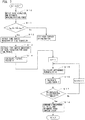
- the acceleration sensor 11 detects the vibration of the tire 1 in the tire circumferential direction during travel, and the braking/driving force estimating means 12 estimates the braking/driving force J applied to the tire (step S10).
- step S12 a time series waveform in which the vibration in the tire circumferential direction, which is the output of the acceleration sensor 11, is arranged in time series is detected, then the time series waveform that is data of tire vibration is subjected to window multiplication by a preset time window, and thus a time series waveform of tire vibration for each time window is extracted (step S13).
- J Max is 0.4 G and J is 0.1 G.
- the first model is DRY (J3), and the other models are four of WET (J3), SNOW (J3), ICE (J3), and the out-of-road-surface HMM (silent).
- step S17 whether or not the calculation of the likelihood Z has been finished for all the models is determined (step S17), and in the case where the calculation is not finished, the process returns to step S15, and a likelihood Z2 of WET (J3), which is the next model, is calculated.
- step S18 the road surface state is determined. Specifically, likelihoods Z1 to Z5 calculated for respective road surface HMMs are compared, and a road surface state corresponding to a road surface HMM with the highest likelihood is determined as the road surface state of the road surface on which the tire is traveling.
- the threshold value J Max is preferably in the range of 0.2 G to 0.8 G.
- the estimated braking/driving force J may be used only for determination of whether or not the determination of the road surface state is to be performed, and, regarding the road surface state, seventeen likelihoods Z1 to Z17 may be compared and a road surface state corresponding to a road surface HMM with the highest likelihood may be determined as the road surface state of the road surface on which the tire is traveling.
- Fig. 8 is a function block diagram of a road surface state determination apparatus 20 according to Embodiment 2.
- 11 represents an acceleration sensor serving as a vibration detection means
- 12 represents a braking/driving force estimating means
- 13 represents a braking/driving force determination means
- 14 represents a vibration waveform detection means
- 15 represents a window multiplying means
- 16 represents a feature vector calculation means
- 21 represents a storage means
- 22 represents a kernel function calculation means
- 23 represents a road surface state determination means.
- each means from the acceleration sensor 11 to the feature vector calculation means 16 which have the same reference signs as in Embodiment 1 is the same as in Embodiment 1.
- the acceleration sensor 11 detects the vibration of the tire 1 during travel in the tire circumferential direction, and the braking/driving force estimating means 12 estimates the braking/driving force J applied to the tire.
- the braking/driving force determination means 13 determines, from the estimated braking/driving force J, whether or not the state of the tire 1 is a state in which determination of the road surface state can be performed, and in the case where the magnitude
- the vibration waveform detection means 14 detects a time series waveform in which vibration in the tire circumferential direction is arranged in time series.
- the window multiplying means 15 subjects the time series waveform of the vibration in the tire circumferential direction to window multiplication with a preset time width (time window width), and thus extracts a time series waveform of tire vibration for each time window.
- the feature vector calculation means 16 calculates a feature vector X t for each time series waveform extracted for each time window.
- vibration levels power values of a filtered wave
- x kt (k 1 to 6) of specific frequency bands obtained by filtering each time series waveform of tire vibration by using band pass filters of 0 to 1 kHz, 1 to 2 kHz, 2 to 3 kHz, 3 to 4 kHz, and 4 to 5 kHz are used.
- the number of feature vectors X t is also N.
- a feature vector of a window number i will be described as X i
- power values that are components of X i will be described as x ki .
- Fig. 9 is a schematic diagram illustrating an input space of the feature vector X i , in which each axis represents a vibration level a ik of a specific frequency band, which is a feature value, and each point represents a feature vector X i .
- the actual input space is a seven-dimensional space in total with the time axis because the number of specific frequency bands is 6, this figure is illustrated in two dimensions (the horizontal axis represents a 1 and the vertical axis represents a 2 ).
- points composing a group C can be distinguished from a group C' composed of feature vectors X' i calculated when the vehicle is driving on a SNOW road surface, whether the vehicle is driving on a DRY road surface or on a SNOW road surface can be determined.
- the storage means 21 stores sixteen road surface models for separating a DRY road surface from the other road surfaces, a WET road surface from the other road surfaces, a SNOW road surface from the other road surfaces, and an ICE road surface from the other road surfaces by a discriminant function f(x) representing a separating hyperplane.
- the road surface models are obtained by learning by using, as input data, a road surface feature vector Y ASV (y jk ), which is a feature vector for each time window calculated from a time series waveform of tire vibration obtained by driving a test car including a tire to which an acceleration sensor is attached on respective road surfaces of DRY, WET, SNOW, and ICE while changing the range of the braking/driving force J applied to the tire 1.
- Y ASV y jk
- tire size may be used for the learning, or a plurality of kinds of tire sizes may be used for the learning.
- SV is an abbreviation of support vector, and represents data in the vicinity of a decision boundary selected by the learning.
- each road surface feature vector Y ASV is similar to that of the feature vector X j described above.
- a time series waveform of tire vibration when driving on a DRY road surface while the braking/driving force J in the range J2 described above is applied to the tire is subjected to window multiplication with a time width T, a time series waveform of tire vibration is extracted for each time window, and a DRY road surface feature vector Y D2 is calculated for each time series waveform extracted for each time window.
- the number of dimensions of a vector y i of the DRY road surface feature vector Y D2 is 6 similarly to the feature vector X i .
- a support vector Y D2SV is selected.
- the storage means 15 does not have to store all Y D2 , and only the selected Y D2SV described above may be stored.
- DRY road surface feature vectors Y D1SV , Y D3SV , and Y D4SV , WET road surface feature vectors Y W1SV to Y W4SV , SNOW road surface feature vectors Y S1SV to Y S4SV , and ICE road surface feature vectors Y I1SV to Y I4SV can be obtained in a similar manner to the DRY road surface feature vector Y D2SV .
- determination of the road surface state is performed in accordance with the estimated braking/driving force J.
- the road surface state is a DRY road surface of a braking/driving force of [Jm], a WET road surface of a braking/driving force of [Jm], a SNOW road surface of a braking/driving force of [Jm], or an ICE road surface of a braking/driving force of [Jm] is determined.
- a road surface of a road surface state of a braking/driving force of [Jm] will be described as an A road surface
- road surface feature vectors Y Am and Y AmSV thereof will be described as Y A and Y ASV .
- the road surface model can be constructed by SVM by using respective road surface feature vectors Y A as learning data as proposed by the present applicants in Japanese Patent Application No. 2012-176779 .
- Fig. 10 is a conceptual diagram illustrating a DRY road surface feature vector Y DSV and a road surface feature vector Y nDSV not of a DRY road surface in an input space, and in this figure, black dots represent road surface feature vectors of DRY road surfaces, and dots of a lighter color represent road surface feature vectors not of a DRY surface.
- both the DRY road surface feature vector and the road surface feature vector not of a DRY road surface are matrices
- the DRY road surface feature vector and the road surface feature vector not of a DRY road surface are each represented as a two-dimensional vector in Fig. 10 for explaining how a group decision boundary is obtained.
- nonlinear classification is performed on road surface feature vectors Y DSV and Y nDSV in the original input space by mapping the road surface feature vectors Y DSV and Y nDSV in a feature space of a higher dimension by nonlinear mapping ⁇ by using a kernel method.
- the data is the road surface feature vectors Y Dj and Y nDj
- w is a weight coefficient
- b is a constant
- ⁇ and ⁇ are indices of a plurality of pieces of learning data.
- ⁇ is a Lagrange multiplier which satisfies ⁇ > 0.
- ⁇ (x ⁇ ) ⁇ (x ⁇ ) is an inner product after mapping x ⁇ and x ⁇ in a high-dimension space by mapping ⁇ .
- the Lagrange multiplier ⁇ can be obtained by using an optimization algorithm such as a gradient descent method or sequential minimal optimization (SMO) on the formula (2) described above.
- an optimization algorithm such as a gradient descent method or sequential minimal optimization (SMO) on the formula (2) described above.
- SMO sequential minimal optimization
- a global alignment kernel function (GA kernel) is used as the kernel function K(x ⁇ , x ⁇ ).
- the local kernel ⁇ ij (x i , x j ) is obtained for each window of a time interval T.
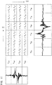
- Fig. 11 illustrates an example in which a GA kernel of the DRY road surface feature vector Y Dj whose number of time windows is 6 and the road surface feature vector Y nDj not of a DRY road surface whose number of time windows is 4 is obtained.
- the local kernel ⁇ ij (x i , x j ) is obtained for each window at a time interval T.
- the DRY road surface and the road surface different from the DRY road surface can be distinguished from each other with a high accuracy by providing a margin to the discriminant function f(x), which is a separating hyperplane that separates the DRY road surface feature vector Y Dj and the road surface feature vector Y nDj not of the DRY road surface.
- Y DSV and Y nDSV described above are present in plural numbers.
- the GA kernel K(X, Y) is a function constituted by the sum or the product of all local kernels ⁇ ij (X i , Y j ) when x i is the feature vector X i and x j is the road surface vector Y Aj or Y nAj in [Math. 3] described above, and can directly compare time series waveforms of different time lengths.
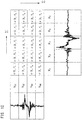
- the degree of similarity between feature vectors X; and Y Aj (or between X i and Y nAj ) can be obtained even in the case where the number n of time series waveforms of time windows in the case of obtaining the feature vector X i and the number m of time series waveforms of time windows in the case of obtaining the road surface feature vector Y Aj (or Y nAj ) are different.
- f D is a discriminant function for distinguishing the DRY road surface from the other road surfaces
- f W is a discriminant function for distinguishing the WET road surface from the other road surfaces
- f S is a discriminant function for distinguishing the SNOW road surface from the other road surfaces
- f I is a discriminant function for distinguishing the ICE road surface from the other road surfaces.
- N DSV is the number of support vectors of the DRY model
- N WSV is the number of support vectors of the WET model
- N SSV is the number of support vectors of the SNOW model
- N ISV is the number of support vectors of the ICE model.
- the discriminant functions f D , f W , f S , and f I are respectively calculated, and the road surface state is determined from the discriminant function indicating the largest value among the calculated discriminant functions f A .
- discriminant functions f D1 , f W1 , f S1 , and f I1 are respectively calculated, and the road surface state is determined from the discriminant function indicating the largest value among calculated discriminant functions f A1 .
- discriminant functions f D2 , f W2 , f S2 , and f I2 are respectively calculated, and the road surface state is determined from the discriminant function indicating the largest value among calculated discriminant functions f A2 .
- the acceleration sensor 11 detects the vibration of the tire 1 in the tire circumferential direction during travel, and the braking/driving force estimating means 12 estimates the braking/driving force J applied to the tire (step S20).
- step S22 a time series waveform in which the vibration in the tire circumferential direction, which is the output of the acceleration sensor 11, is arranged in time series is detected, then the time series waveform that is data of tire vibration is subjected to window multiplication by a preset time window, and thus a time series waveform of tire vibration for each time window is extracted (step S23).
- J Max is 0.4 G and J is 0.1 G.
- the local kernels ⁇ ij (X i , Y j ) are calculated from the feature vector X i , the estimated braking/driving force J, and the support vector Y Ak of the road surface model stored in the storage means 15, then the sum of all the local kernels ⁇ ij (X i , Y j ) is obtained, and global alignment kernel functions K D (X, Y), K W (X, Y), K S (X, Y), and K I (X, Y) are respectively calculated (step S25).
- the support vector is Y Amk and the global alignment kernel functions are K Dm (X, Y), K Wm (X, Y), K Sm (X, Y), and K Im (X, Y) in the case where the range of the estimated braking/driving force J is [Jm], description will be given below by omitting the suffix m.
- step S26 four discriminant functions f D (x), f W (x), f S (x), and f I (x) using the kernel functions K A (X, Y) are respectively calculated (step S26), then the values of the calculated discriminant functions f A (x) are compared, and the road surface state of the discriminant function indicating the largest value is determined as the road surface state of the road surface on which the tire 1 is traveling (step S27).
- the determination of road surface state is performed in accordance with the estimated braking/driving force J in Embodiment 3 described above, a configuration in which the estimated braking/driving force J is used only for determination of whether or not determination of the road surface state is to be performed and the road surface state is determined by using sixteen discriminant functions f D1 to f D4 , f W1 to f W4 , f S1 to f S4 , and f I1 to f I4 may be employed.
- the road surface state determination method of the present invention is:
Landscapes
- Engineering & Computer Science (AREA)
- Mechanical Engineering (AREA)
- Physics & Mathematics (AREA)
- General Physics & Mathematics (AREA)
- Transportation (AREA)
- Theoretical Computer Science (AREA)
- Evolutionary Computation (AREA)
- Environmental & Geological Engineering (AREA)
- Geometry (AREA)
- Medical Informatics (AREA)
- General Engineering & Computer Science (AREA)
- Computer Hardware Design (AREA)
- Artificial Intelligence (AREA)
- Computer Vision & Pattern Recognition (AREA)
- Software Systems (AREA)
- Environmental Sciences (AREA)
- Ecology (AREA)
- Mathematical Physics (AREA)
- Biodiversity & Conservation Biology (AREA)
- Automation & Control Theory (AREA)
- Atmospheric Sciences (AREA)
- Life Sciences & Earth Sciences (AREA)
- Control Of Driving Devices And Active Controlling Of Vehicle (AREA)
- Tires In General (AREA)
Abstract
Description
- The present invention relates to a method of determining a road surface state during travel.
- Conventionally, as a method of determining a road surface state, a method of extracting a time series waveform for each time window by multiplying a time series waveform of tire vibration detected by an acceleration sensor by a window function of a predetermined time width, calculating a feature vector for each time window, then calculating a likelihood of the feature vector for each time window for each road surface model (hidden Markov model) constructed by using, as data for learning, data of the time series waveform of the tire vibration obtained by driving a vehicle including a tire provided with an acceleration sensor on road surfaces of a plurality of road surface states, and determining a road surface corresponding to a road surface model of the highest likelihood as a road surface state of the road surface on which the tire is traveling is proposed (for example, see Patent Literature 1).
- In addition, as a method of determining a road surface state by using a road surface model, a method of calculating a kernel function from a feature vector for each time window and a road surface feature vector that has been obtained in advance, and determining a road surface state by comparing values of another function that identifies a road surface model by using this kernel function is proposed (for example, see Patent Literature 2).
-
- Patent Literature 1: Japanese Patent Application Publication No.
2013-6533 - Patent Literature 2: Japanese Patent Application Publication No.
2014-35279 - However, in
Patent Literature - The present invention has been made in consideration of the conventional problem, and an object thereof is to provide a method by which a road surface state can be determined with a high accuracy even in the case where a braking/driving force is applied to the tire.
- The present invention is a road surface state determination method including a step (a) of detecting vibration of a tire during travel, a step (b) of extracting a time series waveform of the detected vibration of the tire, a step (c) of extracting a time series waveform for each time window by multiplying the time series waveform of the tire vibration by a window function of a predetermined time width, a step (d) of calculating each feature vector from the time series waveform for each time window, and a step (e) of determining a road surface state during travel by using the feature vector for each time window calculated in the step (d) and a road surface model constructed by using, as data for learning, data of time series waveforms of tire vibration obtained by driving, on road surfaces of a plurality of road surface states, a vehicle including a tire provided with an acceleration sensor, wherein the road surface model is constructed in a plural number in accordance with magnitudes of a braking/driving force, wherein a step of estimating a braking/driving force applied to the tire is provided, and wherein, in the step (e), a state of a road surface is determined by using the feature vector and a road surface model corresponding to a magnitude of the estimated braking/driving force.
- When determining a road surface state by using a road surface model as described above, by constructing a plurality of road surface models in accordance with the magnitude of a braking/driving force, the road surface state can be determined with a high accuracy even in the case where a braking/driving force is applied to a tire.
- To be noted, the summary of invention described above does not describe all features required for the present invention, and subcombinations of these features can also be the invention.
-
-
Fig. 1 is a diagram illustrating a configuration of a road surface determination apparatus according toEmbodiment 1 of the present invention. -
Fig. 2 is a diagram illustrating an arrangement example of an acceleration sensor. -
Fig. 3 is a diagram illustrating a time series waveform of tire vibration and an extraction method for a time series waveform of tire vibration for each time window. -
Fig. 4 is a diagram illustrating an example of a road surface HMM. -
Fig. 5 is a diagram illustrating a road surface HMM used for likelihood calculation. -
Fig. 6 is a schematic diagram of a state transition series. -
Fig. 7 is a flowchart illustrating a road surface state determination method according toEmbodiment 1. -
Fig. 8 is a diagram illustrating a configuration of a road surface determination apparatus according toEmbodiment 2. -
Fig. 9 is a schematic diagram illustrating an input space. -
Fig. 10 is a diagram illustrating DRY road surface feature vectors and feature vectors not of a DRY road surface in an input space. -
Fig. 11 is a diagram illustrating a calculation method for a GA kernel of DRY road surface feature vectors and feature vectors not of a DRY road surface. -
Fig. 12 is a diagram illustrating a calculation method for a GA kernel of calculated feature vectors and road surface feature vectors. -
Fig. 13 is a flowchart illustrating a road surface determination method according toEmbodiment 2. -
Fig. 1 is a function block diagram of a road surfacestate determination apparatus 10 according to the present embodiment. In thisfigure, 11 represents an acceleration sensor serving as a vibration detection means, 12 represents a braking/driving force estimating means, 13 represents a braking/driving force determination means, 14 represents a vibration waveform detection means, 15 represents a window multiplying means, 16 represents a feature vector calculation means, 17 represents a storage means, 18 represents a likelihood calculation means, and 19 represents a road surface state determination means. - Each means from the braking/driving force determination means 13 to the road surface state determination means 19 are, for example, constituted by computer software and a storage device such as a RAM, and disposed in a vehicle body that is not illustrated.
- As illustrated in
Fig. 2 , theacceleration sensor 11 is disposed at the center of aninner liner portion 2 of atire 1 in a tire width direction such that the detection direction thereof is a tire circumferential direction, and detects an acceleration rate in the tire circumferential direction input applied from a road surface to atread 3. Hereinafter, a position of the acceleration sensor 11 (strictly, a position on the surface of thetread 3 disposed on the outside of theacceleration sensor 11 in the radial direction) will be referred to as a measurement point. - Output from the
acceleration sensor 11 is, for example, transmitted to the vibration waveform detection means 14 by a transmitter 11F. - The braking/driving force estimating means 12 estimates a braking/driving force J applied to the tire. Specifically, a driving force applied to the tire is estimated from an accelerator opening and a gear position, and a braking force is estimated from a brake pedal pressing force or a brake oil pressure. J > 0 corresponds to a driving force and J < 0 corresponds to a braking force.
- To be noted, the braking/driving force J applied to the tire may be estimated from either or both of information of a vehicle body acceleration rate and road surface slope information, or the braking/driving force J applied to the tire may be estimated from any or a plurality of pieces of information of vehicle body speed, wheel speed, and road surface slope information.
- The braking/driving force determination means 13 determines, from the estimated braking/driving force J, whether or not the state of the
tire 1 is a state in which determination of the road surface state can be performed. Specifically, in the case where the magnitude |J| of the estimated braking/driving force J exceeds a threshold value JMax, it is determined that determination of the road surface state from the detected vibration waveform is difficult, and determination of the road surface state is stopped by transmitting a stopping instruction signal for stopping detection of the vibration waveform to the vibration waveform detection means 14. - In contrast, in the case where the magnitude |J| of the estimated braking/driving force J does not exceed the threshold value JMax (-JMax ≤ J ≤ JMax), data of the braking/driving force J is output to the likelihood calculation means 18.
- To be noted, it is preferable that JMax is within a range of 0.2 G to 0.8 G. In this example, JMax is 0.4 G.
- The vibration waveform detection means 14 detects a time series waveform in which vibration in the tire circumferential direction input to the
tire 1 during travel, which is an output of theacceleration sensor 11, is arranged in time series as illustrated inFig. 3 . - The window multiplying means 15 subjects the time series waveform of the vibration in the tire circumferential direction to window multiplication with a preset time width (time window width) T, and thus extracts a time series waveform of tire vibration for each time window.
- The feature vector calculation means 16 calculates a feature vector Xt for each time series waveform extracted for each time window. In this example, as the feature vector Xt, vibration levels (power values of a filtered wave) xkt of specific frequency bands obtained by filtering each time series waveform of tire vibration by using k band pass filters BP(k) of frequency ranges of fka to fkb. The number of dimensions of a feature vector X is k, and, in this example, since the specific frequency ranges are set to six ranges of 0 to 0.5 kHz, 0.5 to 1 kHz, 1 to 2 kHz, 2 to 3 kHz, 3 to 4 kHz, and 4 to 5 kHz, k is 6.
- Since the feature vector Xt is obtained for each time window, when the total number of time windows is N, the number of feature vectors Xt is also N.
- The storage means 17 stores a plurality of hidden Markov models (hereinafter referred to as road surface HMMs) constituted for respective road surface states and braking driving forces J. A road surface HMM is composed of an in-road-surface HMM (road) and an out-of-road-surface HMM (silent). The in-road-surface HMM (road) is constituted by a vibration waveform appearing in a road surface region in the time series waveform of tire vibration, and the out-of-road-surface HMM (silent) is constituted by a waveform in a region without information.
- The road surface HMM has seven states S1 to S7 corresponding to the time series waveform of tire vibration as illustrated in
Fig. 4 , and the states S1 to S7 are each constituted by two kinds of parameters of emission probabilities bij(X) of the feature vector Xt and transition probabilities aij(X) between states (i, j = 1 to 7). - In this example, learning of dividing the tire vibration into five states in five states of S2 to S6 excluding the start state S1 and the end state S7 of each road surface HMM is performed to obtain the emission probabilities bij(X) and the transition states aij(X) between states of the feature vector X of each road surface HMM.
- An emission probability bij(X) represents the probability of the feature vector X being output when the state transitions from a state S; to a state Sj. The emission probability bij(X) is assumed to have a mixed normal distribution.
- A transition probability aij(X) represents the probability of the state transitioning from the state Si to the state Sj.
- To be noted, in the case where the number of dimensions of the feature vector X is k, the emission probability bij is set for each of k components xk of the feature vector X.
- In this example, data of time series waveform obtained in advance by driving a vehicle including the
tire 1 provided with theacceleration sensor 11 on respective road surfaces of DRY, WET, SNOW, and ICE while changing the range of the braking/driving force J applied to thetire 1 is used as learning data, and thus seventeen road surface HMMs composed of sixteen in-road-surface HMMs (road) and one out-of-road-surface HMM (silent) as illustrated inFIG. 1 are constructed. - In this figure, DRY (J1) is a road surface HMM constructed by using data of a time series waveform of tire vibration obtained by driving on a DRY road surface in a range of braking/driving force J1 = -0.4 G to -0.2 G as learning data, DRY (J2) is a road surface HMM constructed by using data of a time series waveform of tire vibration obtained by driving in a range of braking/driving force J2 = -0.2 G to 0 G as learning data, DRY (J3) is a road surface HMM constructed by using data of a time series waveform of tire vibration obtained by driving in a range of braking/driving force J3 = 0 G to 0.2 G as learning data, and DRY (J4) is a road surface HMM constructed by using data of a time series waveform of tire vibration obtained by driving in a range of braking/driving force J4 = 0.2 G to 0.4 G as learning data.
- The same applies to WET (J1) to WET (J4), SNOW (J1) to SNOW (J4), and ICE (J1) to ICE (J4).
- The likelihood calculation means 18 calculates likelihood of a feature vector Xt (P) corrected for each of a plurality of (five herein) road surface HMMs as illustrated in
Fig. 5 . - The road surface HMMs for which likelihood is to be calculated are the in-road-surface HMMs (road) and the out-of-road-surface HMM in the range Jm (m is one of 1 to 4) of the braking/driving force in which the braking/driving force J output from the braking/driving force determination means 13 is included. For example, in the case where the braking/driving force is J = 0.1 G, the in-road-surface HMMs for which the likelihood is calculated are five including DRY (J3), WET (J3), SNOW (J3), ICE (J3), and the out-of-road-surface HMM (silent).
- Regarding the likelihood, as the present applicants have proposed in Japanese Patent Application No.
2011-140943
[Math. 1]

- X; data series
- t; time
- S; number of states
- Ms; number of components in mixed Gauss distribution
- cjsm; mixture ratio of m-th mixture component
- µ; average vector of Gauss distribution
- σ; variance-covariance matrix of Gauss distribution
- Since the road surface HMM has 7 states, a transition probability π(Xt) can be represented by a 7 × 7 matrix. As this transition probability π(Xt), the transition probability aij(Xt) between states of the feature vector Xt obtained by learning of the road surface HMM described above can be used.
- Then, an appearance probability K(Xt) for each time window, which is a product of the calculated emission probability P(Xt) and the transition probability π(Xt) is obtained, and a likelihood Z is obtained by multiplying the appearance probability K(Xt) for each time window for all time windows. That is, the likelihood Z is obtained by Z = Π P(Xt) • transition probability π(Xt). Alternatively, the likelihood Z may be obtained by calculating a log of the appearance probability K(Xt) calculated for each time window and adding log for all time windows.
- Incidentally, there are a plurality of paths (state transition series) through which the state of the road surface HMM transitions from the state S1 to the state S7 as illustrated in
Fig. 6 . That is, the likelihood Z is different between state transition series for each road surface HMM. - In this example, a state transition series ZM with the highest likelihood Z is obtained by applying a known Viterbi algorithm, this state transition series is set as a state transition series corresponding to the detected time series waveform of tire vibration, and the likelihood ZM is set as Z of the road surface HMM.
- The likelihood ZM is obtained for each road surface HMM.
- The road surface state determination means 19 compares respective likelihoods of a plurality of hidden Markov models calculated by the likelihood calculation means 18, and determines a road surface state corresponding to a hidden Markov model with the highest likelihood as the road surface state of a road surface on which the tire is traveling.
- Next, a determination method of road surface state according to
Embodiment 1 will be described with reference to a flowchart ofFig. 7 . - First, the
acceleration sensor 11 detects the vibration of thetire 1 in the tire circumferential direction during travel, and the braking/driving force estimating means 12 estimates the braking/driving force J applied to the tire (step S10). - Next, whether or not the magnitude |J| of the estimated braking/driving force J is equal to or smaller than the threshold value JMax (-JMax ≤ J ≤ JMax) is determined (step S11).
- In the case where the magnitude |J| of the braking/driving force J is equal to or smaller than the threshold value JMax, the process proceeds to step S12, a time series waveform in which the vibration in the tire circumferential direction, which is the output of the
acceleration sensor 11, is arranged in time series is detected, then the time series waveform that is data of tire vibration is subjected to window multiplication by a preset time window, and thus a time series waveform of tire vibration for each time window is extracted (step S13). - In contrast, in the case where the estimated braking/driving force J is J < -JMax or J > JMax, the extraction of time series waveform of tire vibration is stopped.
- In this example, JMax is 0.4 G and J is 0.1 G.
- In step S14, the feature vector Xt = (x1t, x2t, x3t, x4t, x5t, x6t) is calculated for each time series waveform extracted for each time window.
- Next, the appearance probability K(Xt) = emission probability P(Xt) × transition probability π(Xt) is obtained for each time window for the first (N = 1) road surface HMM (step S15), and a likelihood Z1 of the first road surface HMM is calculated by multiplying the appearance probability K(Xt) for all time windows (step S16). Here, in the case where J = 0.1 G holds, the first model is DRY (J3), and the other models are four of WET (J3), SNOW (J3), ICE (J3), and the out-of-road-surface HMM (silent).
- Next, whether or not the calculation of the likelihood Z has been finished for all the models is determined (step S17), and in the case where the calculation is not finished, the process returns to step S15, and a likelihood Z2 of WET (J3), which is the next model, is calculated.
- In the case where the calculation of the likelihood Z for all the five models has been finished, the process proceeds to step S18, and the road surface state is determined. Specifically, likelihoods Z1 to Z5 calculated for respective road surface HMMs are compared, and a road surface state corresponding to a road surface HMM with the highest likelihood is determined as the road surface state of the road surface on which the tire is traveling.
- To be noted, although four ranges [Jm] of the estimated braking/driving fore J have been set in
Embodiment 2 described above, for example, three ranges of [J1 (braking)] = -0.4 G to -0.1 G, [J2 (uniform)] = -0.1 G to 0.1G, and [J3 (driving)] = 0.1 G to 0.4 G may be set, or five or more ranges may be set. In addition, the threshold value JMax is also not limited to 0.4 G, and it suffices as long as the threshold value JMax is within a range of 0.2 G to 0.8G. This is because in the case of JMax < 0.2 G, the range for correcting the influence of the braking/driving fore J is too narrow and is not practical. In addition, in the case of JMax > 0.8 G, the braking/driving force J is large, and thus calculation of the vibration levels xkt of specific frequency bands, which are components of the feature vector, is difficult. Therefore, the threshold value JMax is preferably in the range of 0.2 G to 0.8 G. - In addition, although the calculation of the likelihood Z for determining the road surface state is performed in accordance with the estimated braking/driving force J in
Embodiment 2 described above, the estimated braking/driving force J may be used only for determination of whether or not the determination of the road surface state is to be performed, and, regarding the road surface state, seventeen likelihoods Z1 to Z17 may be compared and a road surface state corresponding to a road surface HMM with the highest likelihood may be determined as the road surface state of the road surface on which the tire is traveling. -
Fig. 8 is a function block diagram of a road surface state determination apparatus 20 according toEmbodiment 2. In thisfigure, 11 represents an acceleration sensor serving as a vibration detection means, 12 represents a braking/driving force estimating means, 13 represents a braking/driving force determination means, 14 represents a vibration waveform detection means, 15 represents a window multiplying means, 16 represents a feature vector calculation means, 21 represents a storage means, 22 represents a kernel function calculation means, and 23 represents a road surface state determination means. - To be noted, each means from the
acceleration sensor 11 to the feature vector calculation means 16 which have the same reference signs as inEmbodiment 1 is the same as inEmbodiment 1. - That is, the
acceleration sensor 11 detects the vibration of thetire 1 during travel in the tire circumferential direction, and the braking/driving force estimating means 12 estimates the braking/driving force J applied to the tire. - The braking/driving force determination means 13 determines, from the estimated braking/driving force J, whether or not the state of the
tire 1 is a state in which determination of the road surface state can be performed, and in the case where the magnitude |J| of the estimated braking/driving force J is equal to or smaller than the threshold value JMax (-JMax ≤ J ≤ JMax), outputs data of the braking/driving force J to the kernel function calculation means 22. - The vibration waveform detection means 14 detects a time series waveform in which vibration in the tire circumferential direction is arranged in time series.
- The window multiplying means 15 subjects the time series waveform of the vibration in the tire circumferential direction to window multiplication with a preset time width (time window width), and thus extracts a time series waveform of tire vibration for each time window.
- The feature vector calculation means 16 calculates a feature vector Xt for each time series waveform extracted for each time window.
- In this example, as the feature vector Xt, vibration levels (power values of a filtered wave) xkt (k = 1 to 6) of specific frequency bands obtained by filtering each time series waveform of tire vibration by using band pass filters of 0 to 1 kHz, 1 to 2 kHz, 2 to 3 kHz, 3 to 4 kHz, and 4 to 5 kHz are used.
- Since the feature vector Xt is obtained for each time window, when the total number of time windows is N, the number of feature vectors Xt is also N. Hereinafter, a feature vector of a window number i will be described as Xi, and power values that are components of Xi will be described as xki.
-
Fig. 9 is a schematic diagram illustrating an input space of the feature vector Xi, in which each axis represents a vibration level aik of a specific frequency band, which is a feature value, and each point represents a feature vector Xi. Although the actual input space is a seven-dimensional space in total with the time axis because the number of specific frequency bands is 6, this figure is illustrated in two dimensions (the horizontal axis represents a1 and the vertical axis represents a2). - For example, assuming that the vehicle is driving on a DRY road surface, if points composing a group C can be distinguished from a group C' composed of feature vectors X'i calculated when the vehicle is driving on a SNOW road surface, whether the vehicle is driving on a DRY road surface or on a SNOW road surface can be determined.
- The storage means 21 stores sixteen road surface models for separating a DRY road surface from the other road surfaces, a WET road surface from the other road surfaces, a SNOW road surface from the other road surfaces, and an ICE road surface from the other road surfaces by a discriminant function f(x) representing a separating hyperplane.
- The road surface models are obtained by learning by using, as input data, a road surface feature vector YASV(yjk), which is a feature vector for each time window calculated from a time series waveform of tire vibration obtained by driving a test car including a tire to which an acceleration sensor is attached on respective road surfaces of DRY, WET, SNOW, and ICE while changing the range of the braking/driving force J applied to the
tire 1. - To be noted, only one kind of tire size may be used for the learning, or a plurality of kinds of tire sizes may be used for the learning.
- The suffix A of the road surface feature vector YASV(yjk) represents DRY, WET, SNOW, and ICE in which ranges of the braking/driving force J are [J1] = -0.4 G to -0.2 G, [J2] = -0.2 G to 0 G, [J3] = 0 G to 0.2 G, and [J4] = 0.2 G to 0.4 G, that is, DRY (J1) to DRY (J4), WET (J1) to WET (J4), SNOW (J1) to SNOW (J4), and ICE (J1) to ICE (J4) illustrated in
Fig. 8 . - In addition, the suffix j (j = 1 to M) represents the number of time series waveforms (window number) extracted by time windows, and the suffix k indicates a component of a vector. That is, yjk = (aj1, aj2, aj3, aj4, aj5, aj6) holds. In addition, SV is an abbreviation of support vector, and represents data in the vicinity of a decision boundary selected by the learning.
- Hereinafter, the road surface feature vector YASV(yjk) will be simply described as YASV.
- The calculation method for each road surface feature vector YASV is similar to that of the feature vector Xj described above. For example, in the case of a DRY road surface feature vector YD2SV, a time series waveform of tire vibration when driving on a DRY road surface while the braking/driving force J in the range J2 described above is applied to the tire is subjected to window multiplication with a time width T, a time series waveform of tire vibration is extracted for each time window, and a DRY road surface feature vector YD2 is calculated for each time series waveform extracted for each time window. To be noted, the number of dimensions of a vector yi of the DRY road surface feature vector YD2 is 6 similarly to the feature vector Xi. Then, by performing learning by a support vector machine (SVM) by using YD2 as learning data, a support vector YD2SV is selected. To be noted, the storage means 15 does not have to store all YD2, and only the selected YD2SV described above may be stored. DRY road surface feature vectors YD1SV, YD3SV, and YD4SV, WET road surface feature vectors YW1SV to YW4SV, SNOW road surface feature vectors YS1SV to YS4SV, and ICE road surface feature vectors YI1SV to YI4SV can be obtained in a similar manner to the DRY road surface feature vector YD2SV.
- In this example, determination of the road surface state is performed in accordance with the estimated braking/driving force J.
- Specifically, in the case where the estimated braking/driving force J is in a range of [Jm] (m = 1 to 4), whether the road surface state is a DRY road surface of a braking/driving force of [Jm], a WET road surface of a braking/driving force of [Jm], a SNOW road surface of a braking/driving force of [Jm], or an ICE road surface of a braking/driving force of [Jm] is determined.
- Hereinafter, a road surface of a road surface state of a braking/driving force of [Jm] will be described as an A road surface, and road surface feature vectors YAm and YAmSV thereof will be described as YA and YASV.
- The road surface model can be constructed by SVM by using respective road surface feature vectors YA as learning data as proposed by the present applicants in Japanese Patent Application No.
2012-176779
Fig. 10 is a conceptual diagram illustrating a DRY road surface feature vector YDSV and a road surface feature vector YnDSV not of a DRY road surface in an input space, and in this figure, black dots represent road surface feature vectors of DRY road surfaces, and dots of a lighter color represent road surface feature vectors not of a DRY surface. - To be noted, although both the DRY road surface feature vector and the road surface feature vector not of a DRY road surface are matrices, the DRY road surface feature vector and the road surface feature vector not of a DRY road surface are each represented as a two-dimensional vector in
Fig. 10 for explaining how a group decision boundary is obtained. - Generally, linear separation cannot be performed at a group decision boundary. Therefore, nonlinear classification is performed on road surface feature vectors YDSV and YnDSV in the original input space by mapping the road surface feature vectors YDSV and YnDSV in a feature space of a higher dimension by nonlinear mapping ϕ by using a kernel method.
- Specifically, a discriminant function f(x) = wTϕ(x) - b most suitable for identifying data is obtained by using a data set X = (x1, x2, ... xn) and a belonging class z = {1, -1}. Here, the data is the road surface feature vectors YDj and YnDj, a belonging class z = 1 indicates data of a DRY road surface indicated by χ1 in the figure, and z = -1 indicates data of a road surface different from a DRY road surface indicated by χ2. In addition, w is a weight coefficient, b is a constant, and f (x) = 0 corresponds to the decision boundary.
- The discriminant function f(x) = wTϕ(x) - b is optimized by using, for example, a method of Lagrange multiplier. The optimization problem can be replaced by the following formulae (3) and (4).
[Math. 2]

- Here, α and β are indices of a plurality of pieces of learning data. In addition, λ is a Lagrange multiplier which satisfies λ > 0.
- In this case, the discriminant function f(x) = wTϕ(x) - b can be non-linearized by replacing an inner product ϕ(xα)ϕ(xβ) by a kernel function K(xα, xβ). To be noted, ϕ(xα)ϕ(xβ) is an inner product after mapping xα and xβ in a high-dimension space by mapping ϕ.
- The Lagrange multiplier λ can be obtained by using an optimization algorithm such as a gradient descent method or sequential minimal optimization (SMO) on the formula (2) described above. In this case, since a kernel function is used, the high-dimension inner product does not have to be directly obtained. Therefore, the calculation time can be greatly reduced.
- In this example, a global alignment kernel function (GA kernel) is used as the kernel function K(xα, xβ). The GA kernel K(xα, xβ) is a function constituted by the sum or the product of all local kernels κij(xi, xj) representing a degree of similarity between the DRY road surface feature vector xi = YDi and the road surface feature vector xj = YnDj not of a DRY road surface as shown in
Fig. 11 and the following formulae (5) and (6), and can directly compare time series waveforms of different time lengths.
[Math. 3]

- The local kernel κij(xi, xj) is obtained for each window of a time interval T.
- To be noted,
Fig. 11 illustrates an example in which a GA kernel of the DRY road surface feature vector YDj whose number of time windows is 6 and the road surface feature vector YnDj not of a DRY road surface whose number of time windows is 4 is obtained. - The local kernel κij(xi, xj) is obtained for each window at a time interval T.
- To distinguish the DRY road surface and the road surface different from the DRY road surface, the DRY road surface and the road surface different from the DRY road surface can be distinguished from each other with a high accuracy by providing a margin to the discriminant function f(x), which is a separating hyperplane that separates the DRY road surface feature vector YDj and the road surface feature vector YnDj not of the DRY road surface.
- The margin refers to a distance from the separating hyperplane to the closest sample (support vector), the separating hyperplane, which is the decision boundary, is f(x) = 0. All the DRY road surface feature vectors YDj are in a region of f(x) ≥ +1, and the road surface feature vectors YnDj not of the DRY road surface are in a region of f(x) ≤ -1.
- The DRY road surface model that distinguishes the DRY road surface from the other road surfaces is an input space including a support vector YDSV in a distance of f(x) = +1 and a support vector YnDSV in a distance of f(x) = -1. Generally, YDSV and YnDSV described above are present in plural numbers.
- The same applies to a WET model that distinguishes the WET road surface from the other road surfaces, a SNOW model that distinguishes the SNOW road surface from the other road surfaces, and an ICE model that distinguishes the ICE road surface from the other road surfaces.
- The kernel function calculation means 22 respectively calculates GA kernels KD(X, Y), KW(X, Y), KS(X, Y), and KI(X, Y) from the feature vector Xi calculated by the feature vector calculation means 16 and from respective support vectors YASV and YnASV (A = D, W, S, and I) of the DRY model, the WET model, the SNOW model, and the ICE model stored in the storage means 21.
- As illustrated in
Fig. 12 , the GA kernel K(X, Y) is a function constituted by the sum or the product of all local kernels κij(Xi, Yj) when xi is the feature vector Xi and xj is the road surface vector YAj or YnAj in [Math. 3] described above, and can directly compare time series waveforms of different time lengths. To be noted, this figure illustrates an example in which xj is the road surface feature vector YAj, the number of time windows of the feature vector Xi is n = 5, and the number of time windows of the road surface feature vector YAj is m = 4. - As in this example, the degree of similarity between feature vectors X; and YAj (or between Xi and YnAj) can be obtained even in the case where the number n of time series waveforms of time windows in the case of obtaining the feature vector Xi and the number m of time series waveforms of time windows in the case of obtaining the road surface feature vector YAj (or YnAj) are different.
- The road surface state determination means 23 determines the road surface state on the basis of values of four discriminant functions fA(x) (A = D, W, S, and I) using kernel functions KA(X, Y) shown in the following formulae (7) to (10).
[Math. 4]



- In addition, NDSV is the number of support vectors of the DRY model, NWSV is the number of support vectors of the WET model, NSSV is the number of support vectors of the SNOW model, and NISV is the number of support vectors of the ICE model.
- In this example, the discriminant functions fD, fW, fS, and fI are respectively calculated, and the road surface state is determined from the discriminant function indicating the largest value among the calculated discriminant functions fA.
- That is, in the case where the estimated braking/driving force J is in the range of [J1] = -0.4 G to -0.2 G, discriminant functions fD1, fW1, fS1, and fI1 are respectively calculated, and the road surface state is determined from the discriminant function indicating the largest value among calculated discriminant functions fA1. In the case where the estimated braking/driving force J is in the range of [J2] = -0.2 G to 0 G, discriminant functions fD2, fW2, fS2, and fI2 are respectively calculated, and the road surface state is determined from the discriminant function indicating the largest value among calculated discriminant functions fA2.
- The same applies to the cases where the braking/driving force J is [J3] = 0 G to 0.2 G and [J4] = 0.2 G to 0.4 G.
- Next, a determination method of the road surface state according to
Embodiment 3 will be described with reference to a flowchart ofFig. 13 . - First, the
acceleration sensor 11 detects the vibration of thetire 1 in the tire circumferential direction during travel, and the braking/driving force estimating means 12 estimates the braking/driving force J applied to the tire (step S20). - Next, whether or not the magnitude |J| of the estimated braking/driving force J is equal to or smaller than the threshold value JMax (-JMax ≤ J ≤ JMax) is determined (step S21).
- In the case where the magnitude |J| of the braking/driving force J is equal to or smaller than the threshold value JMax, the process proceeds to step S22, a time series waveform in which the vibration in the tire circumferential direction, which is the output of the
acceleration sensor 11, is arranged in time series is detected, then the time series waveform that is data of tire vibration is subjected to window multiplication by a preset time window, and thus a time series waveform of tire vibration for each time window is extracted (step S23). - In contrast, in the case where the estimated braking/driving force J satisfies J < -JMax or J > JMax, the extraction of time series waveform of tire vibration is stopped.
- In this example, JMax is 0.4 G and J is 0.1 G.
- In step S24, the feature vector Xt = (x1t, x2t, x3t, x4t, x5t, x6t) is calculated for each time series waveform extracted for each time window.
- Next, the local kernels κij(Xi, Yj) are calculated from the feature vector Xi, the estimated braking/driving force J, and the support vector YAk of the road surface model stored in the storage means 15, then the sum of all the local kernels κij(Xi, Yj) is obtained, and global alignment kernel functions KD(X, Y), KW(X, Y), KS(X, Y), and KI(X, Y) are respectively calculated (step S25).
- To be noted, although, strictly speaking, the support vector is YAmk and the global alignment kernel functions are KDm(X, Y), KWm(X, Y), KSm(X, Y), and KIm(X, Y) in the case where the range of the estimated braking/driving force J is [Jm], description will be given below by omitting the suffix m.
- Next, four discriminant functions fD(x), fW(x), fS(x), and fI(x) using the kernel functions KA(X, Y) are respectively calculated (step S26), then the values of the calculated discriminant functions fA(x) are compared, and the road surface state of the discriminant function indicating the largest value is determined as the road surface state of the road surface on which the
tire 1 is traveling (step S27). - To be noted, although the determination of road surface state is performed in accordance with the estimated braking/driving force J in
Embodiment 3 described above, a configuration in which the estimated braking/driving force J is used only for determination of whether or not determination of the road surface state is to be performed and the road surface state is determined by using sixteen discriminant functions fD1 to fD4, fW1 to fW4, fS1 to fS4, and fI1 to fI4 may be employed. - Embodiments of the present invention described above can be summarized as follows. That is, the road surface state determination method of the present invention is:
- (1) a road surface state determination method including a step (a) of detecting vibration of a tire during travel, a step (b) of extracting a time series waveform of the detected vibration of the tire, a step (c) of extracting a time series waveform for each time window by multiplying the time series waveform of the tire vibration by a window function of a predetermined time width, a step (d) of calculating each feature vector from the time series waveform for each time window, and a step (e) of determining a road surface state during travel by using the feature vector for each time window calculated in the step (d) and a road surface model constructed by using, as data for learning, data of time series waveforms of tire vibration obtained by driving, on road surfaces of a plurality of road surface states, a vehicle including a tire provided with an acceleration sensor, wherein the road surface model is constructed in a plural number in accordance with magnitudes of a braking/driving force, wherein a step of estimating a braking/driving force applied to the tire is provided, and wherein, in the step (e), a state of a road surface is determined by using the feature vector and a road surface model corresponding to a magnitude of the estimated braking/driving force.
When determining a road surface state by using a road surface model as described above, by constructing a plurality of road surface models in accordance with the magnitude of a braking/driving force, the road surface state can be determined with a high accuracy even in the case where a braking/driving force is applied to a tire. - (2) The road surface models are hidden Markov models constituted in advance for respective road surface states, and in the step (e), a likelihood of the feature vector is calculated for each of the plurality of hidden Markov models, and the road surface state is determined by using the calculated likelihood.
As described above, since the present invention is applied to road surface determination using a hidden Markov model, the determination accuracy of the road surface state can be greatly improved. - (3) In the step (e), a kernel function is calculated from the feature vector for each time window calculated in the step (d) and a road surface feature vector that is a feature vector for each time window calculated from a time series waveform of tire vibration obtained for each road surface state calculated in advance, and then the road surface state is determined on a basis of a discriminant function that identifies the road surface model by using the kernel function.
As described above, since the present invention is applied to road surface determination using a kernel function, the determination accuracy of the road surface state can be greatly improved. - (4) Determination of the road surface state is not performed in a case where a magnitude of the estimated braking/driving force exceeds a preset range.
- As described above, since a configuration in which the determination of road surface state is not performed in the case where the magnitude of the estimated braking/driving force exceeds a preset range is employed, erroneous determination of the road surface state can be prevented.
- 1: tire, 2: inner liner portion, 3: tread, 4: wheel rim, 5: tire air chamber, 10: road surface state determination apparatus, 11: acceleration sensor, 12: braking/driving force estimating means, 13: braking/driving force determination means, 14: vibration waveform detection means, 15: window multiplying means, 16: feature vector calculation means, 17: storage means, 18: likelihood calculation means, 19: road surface state determination means
Claims (4)
- A road surface state determination method comprising:a step (a) of detecting vibration of a tire during travel;a step (b) of extracting a time series waveform of the detected vibration of the tire;a step (c) of extracting a time series waveform for each time window by multiplying the time series waveform of the tire vibration by a window function of a predetermined time width;a step (d) of calculating each feature vector from the time series waveform for each time window; anda step (e) of determining a road surface state during travel by using the feature vector for each time window calculated in the step (d) and a road surface model constructed by using, as data for learning, data of time series waveforms of tire vibration obtained by driving, on road surfaces of a plurality of road surface states, a vehicle including a tire provided with an acceleration sensor,wherein the road surface model is constructed in a plural number in accordance with magnitudes of a braking/driving force,wherein a step of estimating a braking/driving force applied to the tire is provided, andwherein, in the step (e), a state of a road surface is determined by using the feature vector and a road surface model corresponding to a magnitude of the estimated braking/driving force.
- The road surface determination method according to claim 1,
wherein the road surface models are hidden Markov models constituted in advance for respective road surface states, and
wherein, in the step (e), a likelihood of the feature vector is calculated for each of the plurality of hidden Markov models, and the road surface state is determined by using the calculated likelihood. - The road surface state determination method according to claim 1, wherein, in the step (e), a kernel function is calculated from the feature vector for each time window calculated in the step (d) and a road surface feature vector that is a feature vector for each time window calculated from a time series waveform of tire vibration obtained for each road surface state calculated in advance, and then the road surface state is determined on a basis of a discriminant function that identifies the road surface model by using the kernel function.
- The road surface determination method according to any one of claims 1 to 3, wherein determination of the road surface state is not performed in a case where a magnitude of the estimated braking/driving force exceeds a preset range.
Applications Claiming Priority (2)
| Application Number | Priority Date | Filing Date | Title |
|---|---|---|---|
| JP2016131103A JP6673766B2 (en) | 2016-06-30 | 2016-06-30 | Road condition determination method |
| PCT/JP2017/019681 WO2018003366A1 (en) | 2016-06-30 | 2017-05-26 | Road surface state determination method |
Publications (3)
| Publication Number | Publication Date |
|---|---|
| EP3480629A1 true EP3480629A1 (en) | 2019-05-08 |
| EP3480629A4 EP3480629A4 (en) | 2019-05-08 |
| EP3480629B1 EP3480629B1 (en) | 2020-07-22 |
Family
ID=60786975
Family Applications (1)
| Application Number | Title | Priority Date | Filing Date |
|---|---|---|---|
| EP17819733.1A Active EP3480629B1 (en) | 2016-06-30 | 2017-05-26 | Road surface state determination method |
Country Status (5)
| Country | Link |
|---|---|
| US (1) | US20200380185A1 (en) |
| EP (1) | EP3480629B1 (en) |
| JP (1) | JP6673766B2 (en) |
| CN (1) | CN109416412B (en) |
| WO (1) | WO2018003366A1 (en) |
Cited By (1)
| Publication number | Priority date | Publication date | Assignee | Title |
|---|---|---|---|---|
| FR3106112A1 (en) * | 2020-01-13 | 2021-07-16 | Continental Automotive | Method and device for adaptive prediction of a surface weather characteristic of a road segment |
Families Citing this family (12)
| Publication number | Priority date | Publication date | Assignee | Title |
|---|---|---|---|---|
| JP7030531B2 (en) * | 2018-01-15 | 2022-03-07 | 株式会社ブリヂストン | Road surface condition determination method and road surface condition determination device |
| JP6590004B2 (en) | 2018-01-15 | 2019-10-16 | 三菱マテリアル株式会社 | THERMISTOR ELEMENT AND ITS MANUFACTURING METHOD |
| JP7030532B2 (en) * | 2018-01-15 | 2022-03-07 | 株式会社ブリヂストン | Road surface condition determination method and road surface condition determination device |
| US11321976B2 (en) * | 2019-11-06 | 2022-05-03 | Schrader Electronics Limited | Adaptively configuring a tire mounted sensor (TMS) with a vehicle-provided parameter |
| CN111532277B (en) * | 2020-06-01 | 2021-11-30 | 中国第一汽车股份有限公司 | Vehicle terrain recognition system and method and vehicle |
| CN112277540A (en) * | 2020-09-17 | 2021-01-29 | 阜阳师范大学 | Heavy truck tire pressure monitoring system |
| CN111994068B (en) * | 2020-10-29 | 2021-03-16 | 北京航空航天大学 | Intelligent driving automobile control system based on intelligent tire touch perception |
| JP2022127825A (en) * | 2021-02-22 | 2022-09-01 | トヨタ自動車株式会社 | Traveling road determination control device |
| CN113076693B (en) * | 2021-04-02 | 2024-07-30 | 东南大学 | Pavement compaction quality evaluation method based on support vector machine and hidden Markov model |
| CN118434611A (en) * | 2021-12-16 | 2024-08-02 | 阿尔卑斯阿尔派株式会社 | Method for preparing judgment space, method for updating judgment space, method for judging road surface state, judgment space preparing device, and road surface state judging device |
| CN115158274B (en) * | 2022-08-31 | 2022-11-29 | 四川省公路规划勘察设计研究院有限公司 | Long and large longitudinal slope dangerous road section identification method based on truck braking and heavy braking characteristics |
| CN121316854A (en) * | 2024-07-11 | 2026-01-13 | 比亚迪股份有限公司 | Road surface type identification methods, devices, vehicles, and cloud servers |
Family Cites Families (15)
| Publication number | Priority date | Publication date | Assignee | Title |
|---|---|---|---|---|
| FR2764241B1 (en) * | 1997-06-10 | 1999-08-20 | Dassault Electronique | MONITORING A TIRE BY ACCELERATION MEASURE |
| JP3855886B2 (en) * | 2002-08-29 | 2006-12-13 | トヨタ自動車株式会社 | Road surface state change estimation device and automobile equipped with the same |
| CN101275900A (en) * | 2008-05-08 | 2008-10-01 | 江汉大学 | Road surface type recognition method based on wheel vibration |
| JP5165603B2 (en) * | 2009-01-09 | 2013-03-21 | 株式会社ブリヂストン | Tire running state estimation method, steady running state estimation device, tire wear estimation method and apparatus |
| US8561997B2 (en) | 2010-01-05 | 2013-10-22 | General Electric Company | Adverse pressure gradient seal mechanism |
| JP5657917B2 (en) * | 2010-05-19 | 2015-01-21 | 株式会社ブリヂストン | Road surface condition estimation method |
| JP5077402B2 (en) * | 2010-08-17 | 2012-11-21 | トヨタ自動車株式会社 | Traffic control system |
| JP5798341B2 (en) | 2011-02-26 | 2015-10-21 | 株式会社トパック | Automatic packaging machine filling equipment |
| JP5788710B2 (en) * | 2011-05-16 | 2015-10-07 | 株式会社ブリヂストン | Road surface friction coefficient estimation method, vehicle control method, and road surface friction coefficient estimation device |
| JP5837341B2 (en) * | 2011-06-24 | 2015-12-24 | 株式会社ブリヂストン | Road surface condition determination method and apparatus |
| KR20130050113A (en) * | 2011-11-07 | 2013-05-15 | 현대자동차주식회사 | A driving assist system and method having function of steps warning |
| JP5937921B2 (en) * | 2012-08-09 | 2016-06-22 | 株式会社ブリヂストン | Road surface condition determination method and apparatus |
| DE102012112724A1 (en) * | 2012-12-20 | 2014-06-26 | Continental Teves Ag & Co. Ohg | Method for determining a road condition from environmental sensor data |
| SI2757539T1 (en) * | 2013-01-22 | 2020-10-30 | Klimator Ab | A method and an arrangement for collecting and processing data related to road status |
| JP5993804B2 (en) * | 2013-06-12 | 2016-09-14 | 株式会社ブリヂストン | Tire contact state estimation method |
-
2016
- 2016-06-30 JP JP2016131103A patent/JP6673766B2/en active Active
-
2017
- 2017-05-26 WO PCT/JP2017/019681 patent/WO2018003366A1/en not_active Ceased
- 2017-05-26 US US16/305,725 patent/US20200380185A1/en not_active Abandoned
- 2017-05-26 CN CN201780041228.7A patent/CN109416412B/en active Active
- 2017-05-26 EP EP17819733.1A patent/EP3480629B1/en active Active
Cited By (4)
| Publication number | Priority date | Publication date | Assignee | Title |
|---|---|---|---|---|
| FR3106112A1 (en) * | 2020-01-13 | 2021-07-16 | Continental Automotive | Method and device for adaptive prediction of a surface weather characteristic of a road segment |
| WO2021144158A1 (en) * | 2020-01-13 | 2021-07-22 | Continental Automotive Gmbh | Method and device for adaptive prediction of a weather characteristic of a surface of a road segment |
| CN114902083A (en) * | 2020-01-13 | 2022-08-12 | 大陆汽车有限公司 | Adaptive prediction method and device for road surface meteorological characteristics of road section |
| US11630237B2 (en) | 2020-01-13 | 2023-04-18 | Continental Automotive Gmbh | Adaptive method and device for prediction of a weather characteristic of a surface of a road segment |
Also Published As
| Publication number | Publication date |
|---|---|
| WO2018003366A1 (en) | 2018-01-04 |
| JP6673766B2 (en) | 2020-03-25 |
| US20200380185A1 (en) | 2020-12-03 |
| EP3480629B1 (en) | 2020-07-22 |
| CN109416412A (en) | 2019-03-01 |
| JP2018004419A (en) | 2018-01-11 |
| EP3480629A4 (en) | 2019-05-08 |
| CN109416412B (en) | 2021-08-24 |
Similar Documents
| Publication | Publication Date | Title |
|---|---|---|
| EP3480629B1 (en) | Road surface state determination method | |
| EP3480630A1 (en) | Road surface state determination method and road surface state determination device | |
| EP2537723B1 (en) | Method and apparatus for determining road surface condition | |
| US9434387B2 (en) | Method and apparatus for determining road surface condition | |
| JP4764933B2 (en) | Tire pressure drop detection device and method, and tire pressure drop detection program | |
| JP5583338B2 (en) | Operation monitoring method and operation monitoring apparatus | |
| Shao et al. | Adaptive forward collision warning system for hazmat truck drivers: Considering differential driving behavior and risk levels | |
| JP2018004418A (en) | Method and device for determining state of road surface | |
| EP3623850B1 (en) | Road surface condition determining method and road surface condition determining device | |
| JP6734713B2 (en) | Road condition determination method | |
| CN118913720A (en) | Whole vehicle axle testing method | |
| JP7030531B2 (en) | Road surface condition determination method and road surface condition determination device | |
| US20250201039A1 (en) | Method and system for optimizing adas testing | |
| EP3654246B1 (en) | Method, vehicle, system, and storage medium for indicating anomalous vehicle scenario using encoder network and replay buffer | |
| EP3835090B1 (en) | Tire type distinguishing method and tire type distinguishing device | |
| KR20230052765A (en) | Brake pad monitoring device and method | |
| JP7030532B2 (en) | Road surface condition determination method and road surface condition determination device | |
| WO2019244380A1 (en) | Road surface condition determination method and road surface condition determination device | |
| JP2019218023A (en) | Road face state discrimination method and road face state discrimination device |
Legal Events
| Date | Code | Title | Description |
|---|---|---|---|
| STAA | Information on the status of an ep patent application or granted ep patent |
Free format text: STATUS: THE INTERNATIONAL PUBLICATION HAS BEEN MADE |
|
| PUAI | Public reference made under article 153(3) epc to a published international application that has entered the european phase |
Free format text: ORIGINAL CODE: 0009012 |
|
| STAA | Information on the status of an ep patent application or granted ep patent |
Free format text: STATUS: REQUEST FOR EXAMINATION WAS MADE |
|
| 17P | Request for examination filed |
Effective date: 20190115 |
|
| A4 | Supplementary search report drawn up and despatched |
Effective date: 20190326 |
|
| AK | Designated contracting states |
Kind code of ref document: A1 Designated state(s): AL AT BE BG CH CY CZ DE DK EE ES FI FR GB GR HR HU IE IS IT LI LT LU LV MC MK MT NL NO PL PT RO RS SE SI SK SM TR |
|
| AX | Request for extension of the european patent |
Extension state: BA ME |
|
| DAV | Request for validation of the european patent (deleted) | ||
| DAX | Request for extension of the european patent (deleted) | ||
| RIC1 | Information provided on ipc code assigned before grant |
Ipc: G01W 1/00 20060101AFI20191213BHEP Ipc: B60C 23/04 20060101ALI20191213BHEP Ipc: B60W 40/068 20120101ALI20191213BHEP Ipc: B60C 23/06 20060101ALI20191213BHEP Ipc: B60T 8/172 20060101ALI20191213BHEP Ipc: B60C 19/00 20060101ALI20191213BHEP |
|
| GRAP | Despatch of communication of intention to grant a patent |
Free format text: ORIGINAL CODE: EPIDOSNIGR1 |
|
| STAA | Information on the status of an ep patent application or granted ep patent |
Free format text: STATUS: GRANT OF PATENT IS INTENDED |
|
| INTG | Intention to grant announced |
Effective date: 20200128 |
|
| GRAS | Grant fee paid |
Free format text: ORIGINAL CODE: EPIDOSNIGR3 |
|
| GRAA | (expected) grant |
Free format text: ORIGINAL CODE: 0009210 |
|
| STAA | Information on the status of an ep patent application or granted ep patent |
Free format text: STATUS: THE PATENT HAS BEEN GRANTED |
|
| AK | Designated contracting states |
Kind code of ref document: B1 Designated state(s): AL AT BE BG CH CY CZ DE DK EE ES FI FR GB GR HR HU IE IS IT LI LT LU LV MC MK MT NL NO PL PT RO RS SE SI SK SM TR |
|
| REG | Reference to a national code |
Ref country code: GB Ref legal event code: FG4D |
|
| REG | Reference to a national code |
Ref country code: CH Ref legal event code: EP |
|
| REG | Reference to a national code |
Ref country code: DE Ref legal event code: R096 Ref document number: 602017020339 Country of ref document: DE |
|
| REG | Reference to a national code |
Ref country code: AT Ref legal event code: REF Ref document number: 1293940 Country of ref document: AT Kind code of ref document: T Effective date: 20200815 |
|
| REG | Reference to a national code |
Ref country code: IE Ref legal event code: FG4D |
|
| REG | Reference to a national code |
Ref country code: LT Ref legal event code: MG4D |
|
| REG | Reference to a national code |
Ref country code: AT Ref legal event code: MK05 Ref document number: 1293940 Country of ref document: AT Kind code of ref document: T Effective date: 20200722 |
|
| PG25 | Lapsed in a contracting state [announced via postgrant information from national office to epo] |
Ref country code: NO Free format text: LAPSE BECAUSE OF FAILURE TO SUBMIT A TRANSLATION OF THE DESCRIPTION OR TO PAY THE FEE WITHIN THE PRESCRIBED TIME-LIMIT Effective date: 20201022 Ref country code: SE Free format text: LAPSE BECAUSE OF FAILURE TO SUBMIT A TRANSLATION OF THE DESCRIPTION OR TO PAY THE FEE WITHIN THE PRESCRIBED TIME-LIMIT Effective date: 20200722 Ref country code: GR Free format text: LAPSE BECAUSE OF FAILURE TO SUBMIT A TRANSLATION OF THE DESCRIPTION OR TO PAY THE FEE WITHIN THE PRESCRIBED TIME-LIMIT Effective date: 20201023 Ref country code: FI Free format text: LAPSE BECAUSE OF FAILURE TO SUBMIT A TRANSLATION OF THE DESCRIPTION OR TO PAY THE FEE WITHIN THE PRESCRIBED TIME-LIMIT Effective date: 20200722 Ref country code: LT Free format text: LAPSE BECAUSE OF FAILURE TO SUBMIT A TRANSLATION OF THE DESCRIPTION OR TO PAY THE FEE WITHIN THE PRESCRIBED TIME-LIMIT Effective date: 20200722 Ref country code: HR Free format text: LAPSE BECAUSE OF FAILURE TO SUBMIT A TRANSLATION OF THE DESCRIPTION OR TO PAY THE FEE WITHIN THE PRESCRIBED TIME-LIMIT Effective date: 20200722 Ref country code: AT Free format text: LAPSE BECAUSE OF FAILURE TO SUBMIT A TRANSLATION OF THE DESCRIPTION OR TO PAY THE FEE WITHIN THE PRESCRIBED TIME-LIMIT Effective date: 20200722 Ref country code: BG Free format text: LAPSE BECAUSE OF FAILURE TO SUBMIT A TRANSLATION OF THE DESCRIPTION OR TO PAY THE FEE WITHIN THE PRESCRIBED TIME-LIMIT Effective date: 20201022 Ref country code: ES Free format text: LAPSE BECAUSE OF FAILURE TO SUBMIT A TRANSLATION OF THE DESCRIPTION OR TO PAY THE FEE WITHIN THE PRESCRIBED TIME-LIMIT Effective date: 20200722 Ref country code: PT Free format text: LAPSE BECAUSE OF FAILURE TO SUBMIT A TRANSLATION OF THE DESCRIPTION OR TO PAY THE FEE WITHIN THE PRESCRIBED TIME-LIMIT Effective date: 20201123 |
|
| PG25 | Lapsed in a contracting state [announced via postgrant information from national office to epo] |
Ref country code: PL Free format text: LAPSE BECAUSE OF FAILURE TO SUBMIT A TRANSLATION OF THE DESCRIPTION OR TO PAY THE FEE WITHIN THE PRESCRIBED TIME-LIMIT Effective date: 20200722 Ref country code: LV Free format text: LAPSE BECAUSE OF FAILURE TO SUBMIT A TRANSLATION OF THE DESCRIPTION OR TO PAY THE FEE WITHIN THE PRESCRIBED TIME-LIMIT Effective date: 20200722 Ref country code: RS Free format text: LAPSE BECAUSE OF FAILURE TO SUBMIT A TRANSLATION OF THE DESCRIPTION OR TO PAY THE FEE WITHIN THE PRESCRIBED TIME-LIMIT Effective date: 20200722 Ref country code: IS Free format text: LAPSE BECAUSE OF FAILURE TO SUBMIT A TRANSLATION OF THE DESCRIPTION OR TO PAY THE FEE WITHIN THE PRESCRIBED TIME-LIMIT Effective date: 20201122 |
|
| PG25 | Lapsed in a contracting state [announced via postgrant information from national office to epo] |
Ref country code: NL Free format text: LAPSE BECAUSE OF FAILURE TO SUBMIT A TRANSLATION OF THE DESCRIPTION OR TO PAY THE FEE WITHIN THE PRESCRIBED TIME-LIMIT Effective date: 20200722 |
|
| REG | Reference to a national code |
Ref country code: DE Ref legal event code: R097 Ref document number: 602017020339 Country of ref document: DE |
|
| PG25 | Lapsed in a contracting state [announced via postgrant information from national office to epo] |
Ref country code: RO Free format text: LAPSE BECAUSE OF FAILURE TO SUBMIT A TRANSLATION OF THE DESCRIPTION OR TO PAY THE FEE WITHIN THE PRESCRIBED TIME-LIMIT Effective date: 20200722 Ref country code: DK Free format text: LAPSE BECAUSE OF FAILURE TO SUBMIT A TRANSLATION OF THE DESCRIPTION OR TO PAY THE FEE WITHIN THE PRESCRIBED TIME-LIMIT Effective date: 20200722 Ref country code: CZ Free format text: LAPSE BECAUSE OF FAILURE TO SUBMIT A TRANSLATION OF THE DESCRIPTION OR TO PAY THE FEE WITHIN THE PRESCRIBED TIME-LIMIT Effective date: 20200722 Ref country code: EE Free format text: LAPSE BECAUSE OF FAILURE TO SUBMIT A TRANSLATION OF THE DESCRIPTION OR TO PAY THE FEE WITHIN THE PRESCRIBED TIME-LIMIT Effective date: 20200722 Ref country code: SM Free format text: LAPSE BECAUSE OF FAILURE TO SUBMIT A TRANSLATION OF THE DESCRIPTION OR TO PAY THE FEE WITHIN THE PRESCRIBED TIME-LIMIT Effective date: 20200722 Ref country code: IT Free format text: LAPSE BECAUSE OF FAILURE TO SUBMIT A TRANSLATION OF THE DESCRIPTION OR TO PAY THE FEE WITHIN THE PRESCRIBED TIME-LIMIT Effective date: 20200722 |
|
| PLBE | No opposition filed within time limit |
Free format text: ORIGINAL CODE: 0009261 |
|
| STAA | Information on the status of an ep patent application or granted ep patent |
Free format text: STATUS: NO OPPOSITION FILED WITHIN TIME LIMIT |
|
| PG25 | Lapsed in a contracting state [announced via postgrant information from national office to epo] |
Ref country code: AL Free format text: LAPSE BECAUSE OF FAILURE TO SUBMIT A TRANSLATION OF THE DESCRIPTION OR TO PAY THE FEE WITHIN THE PRESCRIBED TIME-LIMIT Effective date: 20200722 |
|
| 26N | No opposition filed |
Effective date: 20210423 |
|
| PG25 | Lapsed in a contracting state [announced via postgrant information from national office to epo] |
Ref country code: SK Free format text: LAPSE BECAUSE OF FAILURE TO SUBMIT A TRANSLATION OF THE DESCRIPTION OR TO PAY THE FEE WITHIN THE PRESCRIBED TIME-LIMIT Effective date: 20200722 |
|
| PG25 | Lapsed in a contracting state [announced via postgrant information from national office to epo] |
Ref country code: SI Free format text: LAPSE BECAUSE OF FAILURE TO SUBMIT A TRANSLATION OF THE DESCRIPTION OR TO PAY THE FEE WITHIN THE PRESCRIBED TIME-LIMIT Effective date: 20200722 |
|
| REG | Reference to a national code |
Ref country code: NL Ref legal event code: MP Effective date: 20200722 |
|
| REG | Reference to a national code |
Ref country code: CH Ref legal event code: PL |
|
| GBPC | Gb: european patent ceased through non-payment of renewal fee |
Effective date: 20210526 |
|
| PG25 | Lapsed in a contracting state [announced via postgrant information from national office to epo] |
Ref country code: MC Free format text: LAPSE BECAUSE OF FAILURE TO SUBMIT A TRANSLATION OF THE DESCRIPTION OR TO PAY THE FEE WITHIN THE PRESCRIBED TIME-LIMIT Effective date: 20200722 Ref country code: CH Free format text: LAPSE BECAUSE OF NON-PAYMENT OF DUE FEES Effective date: 20210531 Ref country code: LU Free format text: LAPSE BECAUSE OF NON-PAYMENT OF DUE FEES Effective date: 20210526 Ref country code: LI Free format text: LAPSE BECAUSE OF NON-PAYMENT OF DUE FEES Effective date: 20210531 |
|
| REG | Reference to a national code |
Ref country code: BE Ref legal event code: MM Effective date: 20210531 |
|
| PG25 | Lapsed in a contracting state [announced via postgrant information from national office to epo] |
Ref country code: IE Free format text: LAPSE BECAUSE OF NON-PAYMENT OF DUE FEES Effective date: 20210526 Ref country code: GB Free format text: LAPSE BECAUSE OF NON-PAYMENT OF DUE FEES Effective date: 20210526 |
|
| PG25 | Lapsed in a contracting state [announced via postgrant information from national office to epo] |
Ref country code: BE Free format text: LAPSE BECAUSE OF NON-PAYMENT OF DUE FEES Effective date: 20210531 |
|
| PG25 | Lapsed in a contracting state [announced via postgrant information from national office to epo] |
Ref country code: CY Free format text: LAPSE BECAUSE OF FAILURE TO SUBMIT A TRANSLATION OF THE DESCRIPTION OR TO PAY THE FEE WITHIN THE PRESCRIBED TIME-LIMIT Effective date: 20200722 |
|
| P01 | Opt-out of the competence of the unified patent court (upc) registered |
Effective date: 20230531 |
|
| PG25 | Lapsed in a contracting state [announced via postgrant information from national office to epo] |
Ref country code: HU Free format text: LAPSE BECAUSE OF FAILURE TO SUBMIT A TRANSLATION OF THE DESCRIPTION OR TO PAY THE FEE WITHIN THE PRESCRIBED TIME-LIMIT; INVALID AB INITIO Effective date: 20170526 |
|
| PGFP | Annual fee paid to national office [announced via postgrant information from national office to epo] |
Ref country code: FR Payment date: 20230526 Year of fee payment: 7 |
|
| PG25 | Lapsed in a contracting state [announced via postgrant information from national office to epo] |
Ref country code: MK Free format text: LAPSE BECAUSE OF FAILURE TO SUBMIT A TRANSLATION OF THE DESCRIPTION OR TO PAY THE FEE WITHIN THE PRESCRIBED TIME-LIMIT Effective date: 20200722 |
|
| PG25 | Lapsed in a contracting state [announced via postgrant information from national office to epo] |
Ref country code: MT Free format text: LAPSE BECAUSE OF FAILURE TO SUBMIT A TRANSLATION OF THE DESCRIPTION OR TO PAY THE FEE WITHIN THE PRESCRIBED TIME-LIMIT Effective date: 20200722 |
|
| PG25 | Lapsed in a contracting state [announced via postgrant information from national office to epo] |
Ref country code: FR Free format text: LAPSE BECAUSE OF NON-PAYMENT OF DUE FEES Effective date: 20240531 |
|
| PGFP | Annual fee paid to national office [announced via postgrant information from national office to epo] |
Ref country code: DE Payment date: 20250521 Year of fee payment: 9 |
|
| PG25 | Lapsed in a contracting state [announced via postgrant information from national office to epo] |
Ref country code: TR Free format text: LAPSE BECAUSE OF FAILURE TO SUBMIT A TRANSLATION OF THE DESCRIPTION OR TO PAY THE FEE WITHIN THE PRESCRIBED TIME-LIMIT Effective date: 20200722 |