EP3480569A1 - Sound output device and musical instrument - Google Patents
Sound output device and musical instrument Download PDFInfo
- Publication number
- EP3480569A1 EP3480569A1 EP18204313.3A EP18204313A EP3480569A1 EP 3480569 A1 EP3480569 A1 EP 3480569A1 EP 18204313 A EP18204313 A EP 18204313A EP 3480569 A1 EP3480569 A1 EP 3480569A1
- Authority
- EP
- European Patent Office
- Prior art keywords
- sensor
- output device
- output
- circuit
- thermistor
- Prior art date
- Legal status (The legal status is an assumption and is not a legal conclusion. Google has not performed a legal analysis and makes no representation as to the accuracy of the status listed.)
- Granted
Links
Images




Classifications
-
- H—ELECTRICITY
- H04—ELECTRIC COMMUNICATION TECHNIQUE
- H04R—LOUDSPEAKERS, MICROPHONES, GRAMOPHONE PICK-UPS OR LIKE ACOUSTIC ELECTROMECHANICAL TRANSDUCERS; ELECTRIC HEARING AIDS; PUBLIC ADDRESS SYSTEMS
- H04R17/00—Piezoelectric transducers; Electrostrictive transducers
-
- G—PHYSICS
- G01—MEASURING; TESTING
- G01H—MEASUREMENT OF MECHANICAL VIBRATIONS OR ULTRASONIC, SONIC OR INFRASONIC WAVES
- G01H11/00—Measuring mechanical vibrations or ultrasonic, sonic or infrasonic waves by detecting changes in electric or magnetic properties
- G01H11/06—Measuring mechanical vibrations or ultrasonic, sonic or infrasonic waves by detecting changes in electric or magnetic properties by electric means
- G01H11/08—Measuring mechanical vibrations or ultrasonic, sonic or infrasonic waves by detecting changes in electric or magnetic properties by electric means using piezoelectric devices
-
- G—PHYSICS
- G10—MUSICAL INSTRUMENTS; ACOUSTICS
- G10H—ELECTROPHONIC MUSICAL INSTRUMENTS; INSTRUMENTS IN WHICH THE TONES ARE GENERATED BY ELECTROMECHANICAL MEANS OR ELECTRONIC GENERATORS, OR IN WHICH THE TONES ARE SYNTHESISED FROM A DATA STORE
- G10H3/00—Instruments in which the tones are generated by electromechanical means
- G10H3/12—Instruments in which the tones are generated by electromechanical means using mechanical resonant generators, e.g. strings or percussive instruments, the tones of which are picked up by electromechanical transducers, the electrical signals being further manipulated or amplified and subsequently converted to sound by a loudspeaker or equivalent instrument
- G10H3/14—Instruments in which the tones are generated by electromechanical means using mechanical resonant generators, e.g. strings or percussive instruments, the tones of which are picked up by electromechanical transducers, the electrical signals being further manipulated or amplified and subsequently converted to sound by a loudspeaker or equivalent instrument using mechanically actuated vibrators with pick-up means
- G10H3/146—Instruments in which the tones are generated by electromechanical means using mechanical resonant generators, e.g. strings or percussive instruments, the tones of which are picked up by electromechanical transducers, the electrical signals being further manipulated or amplified and subsequently converted to sound by a loudspeaker or equivalent instrument using mechanically actuated vibrators with pick-up means using a membrane, e.g. a drum; Pick-up means for vibrating surfaces, e.g. housing of an instrument
-
- H—ELECTRICITY
- H10—SEMICONDUCTOR DEVICES; ELECTRIC SOLID-STATE DEVICES NOT OTHERWISE PROVIDED FOR
- H10N—ELECTRIC SOLID-STATE DEVICES NOT OTHERWISE PROVIDED FOR
- H10N30/00—Piezoelectric or electrostrictive devices
- H10N30/30—Piezoelectric or electrostrictive devices with mechanical input and electrical output, e.g. functioning as generators or sensors
- H10N30/302—Sensors
-
- H—ELECTRICITY
- H10—SEMICONDUCTOR DEVICES; ELECTRIC SOLID-STATE DEVICES NOT OTHERWISE PROVIDED FOR
- H10N—ELECTRIC SOLID-STATE DEVICES NOT OTHERWISE PROVIDED FOR
- H10N30/00—Piezoelectric or electrostrictive devices
- H10N30/80—Constructional details
- H10N30/802—Circuitry or processes for operating piezoelectric or electrostrictive devices not otherwise provided for, e.g. drive circuits
-
- H—ELECTRICITY
- H10—SEMICONDUCTOR DEVICES; ELECTRIC SOLID-STATE DEVICES NOT OTHERWISE PROVIDED FOR
- H10N—ELECTRIC SOLID-STATE DEVICES NOT OTHERWISE PROVIDED FOR
- H10N30/00—Piezoelectric or electrostrictive devices
- H10N30/80—Constructional details
- H10N30/85—Piezoelectric or electrostrictive active materials
- H10N30/857—Macromolecular compositions
-
- G—PHYSICS
- G10—MUSICAL INSTRUMENTS; ACOUSTICS
- G10H—ELECTROPHONIC MUSICAL INSTRUMENTS; INSTRUMENTS IN WHICH THE TONES ARE GENERATED BY ELECTROMECHANICAL MEANS OR ELECTRONIC GENERATORS, OR IN WHICH THE TONES ARE SYNTHESISED FROM A DATA STORE
- G10H2220/00—Input/output interfacing specifically adapted for electrophonic musical tools or instruments
- G10H2220/461—Transducers, i.e. details, positioning or use of assemblies to detect and convert mechanical vibrations or mechanical strains into an electrical signal, e.g. audio, trigger or control signal
- G10H2220/525—Piezoelectric transducers for vibration sensing or vibration excitation in the audio range; Piezoelectric strain sensing, e.g. as key velocity sensor; Piezoelectric actuators, e.g. key actuation in response to a control voltage
- G10H2220/531—Piezoelectric transducers for vibration sensing or vibration excitation in the audio range; Piezoelectric strain sensing, e.g. as key velocity sensor; Piezoelectric actuators, e.g. key actuation in response to a control voltage made of piezoelectric film
-
- G—PHYSICS
- G10—MUSICAL INSTRUMENTS; ACOUSTICS
- G10H—ELECTROPHONIC MUSICAL INSTRUMENTS; INSTRUMENTS IN WHICH THE TONES ARE GENERATED BY ELECTROMECHANICAL MEANS OR ELECTRONIC GENERATORS, OR IN WHICH THE TONES ARE SYNTHESISED FROM A DATA STORE
- G10H2220/00—Input/output interfacing specifically adapted for electrophonic musical tools or instruments
- G10H2220/461—Transducers, i.e. details, positioning or use of assemblies to detect and convert mechanical vibrations or mechanical strains into an electrical signal, e.g. audio, trigger or control signal
- G10H2220/525—Piezoelectric transducers for vibration sensing or vibration excitation in the audio range; Piezoelectric strain sensing, e.g. as key velocity sensor; Piezoelectric actuators, e.g. key actuation in response to a control voltage
- G10H2220/555—Bimorph transducers, i.e. piezoelectric bending multilayer structures with one or more piezoelectric layers, e.g. piezo on metal, serial bimorph or parallel bimorph
-
- G—PHYSICS
- G10—MUSICAL INSTRUMENTS; ACOUSTICS
- G10H—ELECTROPHONIC MUSICAL INSTRUMENTS; INSTRUMENTS IN WHICH THE TONES ARE GENERATED BY ELECTROMECHANICAL MEANS OR ELECTRONIC GENERATORS, OR IN WHICH THE TONES ARE SYNTHESISED FROM A DATA STORE
- G10H2230/00—General physical, ergonomic or hardware implementation of electrophonic musical tools or instruments, e.g. shape or architecture
- G10H2230/045—Special instrument [spint], i.e. mimicking the ergonomy, shape, sound or other characteristic of a specific acoustic musical instrument category
- G10H2230/251—Spint percussion, i.e. mimicking percussion instruments; Electrophonic musical instruments with percussion instrument features; Electrophonic aspects of acoustic percussion instruments or MIDI-like control therefor
- G10H2230/255—Spint xylophone, i.e. mimicking any multi-toned percussion instrument with a multiplicity of tuned resonating bodies, regardless of their material or shape, e.g. xylophone, vibraphone, lithophone, metallophone, marimba, balafon, ranat, gamban, anklong
-
- G—PHYSICS
- G10—MUSICAL INSTRUMENTS; ACOUSTICS
- G10H—ELECTROPHONIC MUSICAL INSTRUMENTS; INSTRUMENTS IN WHICH THE TONES ARE GENERATED BY ELECTROMECHANICAL MEANS OR ELECTRONIC GENERATORS, OR IN WHICH THE TONES ARE SYNTHESISED FROM A DATA STORE
- G10H3/00—Instruments in which the tones are generated by electromechanical means
- G10H3/12—Instruments in which the tones are generated by electromechanical means using mechanical resonant generators, e.g. strings or percussive instruments, the tones of which are picked up by electromechanical transducers, the electrical signals being further manipulated or amplified and subsequently converted to sound by a loudspeaker or equivalent instrument
- G10H3/14—Instruments in which the tones are generated by electromechanical means using mechanical resonant generators, e.g. strings or percussive instruments, the tones of which are picked up by electromechanical transducers, the electrical signals being further manipulated or amplified and subsequently converted to sound by a loudspeaker or equivalent instrument using mechanically actuated vibrators with pick-up means
- G10H3/18—Instruments in which the tones are generated by electromechanical means using mechanical resonant generators, e.g. strings or percussive instruments, the tones of which are picked up by electromechanical transducers, the electrical signals being further manipulated or amplified and subsequently converted to sound by a loudspeaker or equivalent instrument using mechanically actuated vibrators with pick-up means using a string, e.g. electric guitar
- G10H3/181—Details of pick-up assemblies
-
- H—ELECTRICITY
- H04—ELECTRIC COMMUNICATION TECHNIQUE
- H04R—LOUDSPEAKERS, MICROPHONES, GRAMOPHONE PICK-UPS OR LIKE ACOUSTIC ELECTROMECHANICAL TRANSDUCERS; ELECTRIC HEARING AIDS; PUBLIC ADDRESS SYSTEMS
- H04R19/00—Electrostatic transducers
- H04R19/01—Electrostatic transducers characterised by the use of electrets
- H04R19/013—Electrostatic transducers characterised by the use of electrets for loudspeakers
-
- H—ELECTRICITY
- H04—ELECTRIC COMMUNICATION TECHNIQUE
- H04R—LOUDSPEAKERS, MICROPHONES, GRAMOPHONE PICK-UPS OR LIKE ACOUSTIC ELECTROMECHANICAL TRANSDUCERS; ELECTRIC HEARING AIDS; PUBLIC ADDRESS SYSTEMS
- H04R19/00—Electrostatic transducers
- H04R19/01—Electrostatic transducers characterised by the use of electrets
- H04R19/016—Electrostatic transducers characterised by the use of electrets for microphones
-
- H—ELECTRICITY
- H04—ELECTRIC COMMUNICATION TECHNIQUE
- H04R—LOUDSPEAKERS, MICROPHONES, GRAMOPHONE PICK-UPS OR LIKE ACOUSTIC ELECTROMECHANICAL TRANSDUCERS; ELECTRIC HEARING AIDS; PUBLIC ADDRESS SYSTEMS
- H04R3/00—Circuits for transducers
-
- H—ELECTRICITY
- H10—SEMICONDUCTOR DEVICES; ELECTRIC SOLID-STATE DEVICES NOT OTHERWISE PROVIDED FOR
- H10N—ELECTRIC SOLID-STATE DEVICES NOT OTHERWISE PROVIDED FOR
- H10N30/00—Piezoelectric or electrostrictive devices
- H10N30/80—Constructional details
- H10N30/87—Electrodes or interconnections, e.g. leads or terminals
Definitions
- the present invention relates to a sensor output device that includes a piezoelectric element containing porous resin, a sound output device, and a musical instrument that includes the sound output device.
- a vibration detection sensor has been known that is attached on a vibrating part of an object in which vibration detection is performed and that is capable of detecting vibration of the vibrating part and outputting the vibration as an electrical signal.
- a sensor has been known in which a piezoelectric element is used.
- the piezoelectric element includes a porous resin film with electrode layers disposed on both faces of the porous resin film (for example, see Japanese Unexamined Patent Application, First Publication No. 2010-89495 ).
- a sensor that includes such a sheet-like piezoelectric element containing porous resin is suited to detection of sound owing to the softness of the sensor in the thickness direction, and does not inhibit vibration of the object in which vibration detection is performed owing to lightweight properties and thinness of the sensor. Therefore, a sensor that includes such a piezoelectric element containing porous resin is suitably used as a pickup for a musical instrument that detects both vibration and sound.
- the temperature dependence of the sensitivity is high, with the output level of the sensor greatly varying depending on the ambient temperature. Therefore, when used as a pickup for a musical instrument, for example, the temperature of the sensor rises due to illumination on the stage or the like, leading to a large fluctuation in the output level of the sensor.
- the present invention has been made in view of the above circumstances, and an object of the present invention is to provide a sensor output device that includes a sensor including a piezoelectric element that contains porous resin and that is capable of temperature compensation for suppressing fluctuation in the output level due to temperature change, a sound output device, and a musical instrument that includes the sound output device.
- a sensor output device includes: a sensor that includes a piezoelectric element and an output terminal, the piezoelectric element including porous resin; and an output circuit that includes a thermistor, the thermistor connecting the output terminal of the sensor to ground.
- a sensor output device includes: a sensor that includes a piezoelectric element that includes porous resin; and an output circuit that is connected with the sensor, the output circuit including an operational amplifier and a feedback circuit, the feedback circuit including a thermistor connected with the operational amplifier.
- a sensor output device that includes a sensor including a piezoelectric element containing porous resin and that is capable of temperature compensation for suppressing fluctuation in the output level due to temperature change, and a musical instrument that includes the sensor output device.
- a sensor output device 100 according to a first embodiment of the present invention will be described in detail hereinbelow, referring to FIG. 1 to FIG. 6 .
- the thickness and dimension ratio of each constitutional element have been suitably adjusted.
- FIG. 1 is a block diagram showing the sensor output device 100.
- the sensor output device 100 includes a sheet sensor 1 and a sensor output circuit 2.
- the sheet sensor 1 and the sensor output circuit (output circuit) 2 are housed in one case (that is, in the same case).
- FIG. 10 shows that the sheet sensor 1 and the sensor output circuit 2 are housed in the case of the sensor output device 100.
- FIG. 2 is a side view of the sheet sensor 1 shown in FIG. 1 .
- the sheet sensor (sensor) 1 is a sensor that includes a sheet-shaped piezoelectric element 11 containing porous resin.
- the piezoelectric element 11 includes electrode layers 13 (a first electrode layer 13a and a second electrode layer 13b) laminated on both sides of an electretized film 12 as shown in FIG. 2 .
- the electretized film 12 is a sheet-like film containing porous resin.
- the electretized film 12 is obtained by the following manner. First, a resin film consisting of an electrolyte layer provided on at least one surface of a porous layer is permeated with a non-reactive gas under a high-pressure condition. Subsequently the resin film is thermally treated under reduced pressure to obtain a porous resin film. The porous resin film is then electretized by a direct-current high-voltage discharge treatment, and thereby the electretized film 12 is obtained (for example, see Japanese Unexamined Patent Application, First Publication No. 2010-89495 ).
- the electretized film 12 is obtained by electretizing the porous resin film containing a porous layer capable of holding electric charges therein, and can stably hold electric charges for a long period of time.
- the electretized film 12 is known to exhibit a piezoelectric effect and so can be used for vibration measurement, vibration control, sound generation, sound detection, and the like. Therefore, by making use of the light weight, the electretized film 12 can be used for transducers in audio equipment such as speakers, headphones, microphones and the like and for flexible sheet-shaped pressure sensors.
- the electrode layer 13 is laminated on both surfaces of the electretized film 12.
- the electrode layer 13 includes the first electrode layer 13a and the second electrode layer 13b.
- the first electrode layer 13a and the second electrode layer 13b are connected to respective lead wires (not shown in the figure), with one of the lead wires connected to an output terminal 14 and the other to ground.
- the material for forming the first electrode layer 13a and the second electrode layer 13b is not particularly limited as long as the material is electrically conductive, and examples thereof include various types of metals such as aluminum and silver, alloys of these metals, carbon and the like.
- the sheet sensor 1 that includes such a piezoelectric element 11 containing porous resin is suited for detection of sound due to being flexible in the thickness direction, and also does not inhibit vibration of a musical instrument owing to the lightweight properties and thinness thereof. Therefore, the sheet sensor 1 is suitably used as a musical instrument pickup that detects both vibration and sound.
- sound as referred to means a compressional wave transmitted through air
- vibration as referred to means vibration that propagates in a solid to a sensor.
- FIG. 3 is a graph that shows the relationship between the temperature of the sheet sensor 1 and the sensor sensitivity.
- the sensor sensitivity of the sheet sensor 1 increases as the temperature rises owing to the characteristics of the material, and so the voltage level of the output signal from the sheet sensor 1 increases.
- the temperature dependence is about +0.2 db/°C.
- the sheet sensor 1 has a linear temperature dependence in a range from 0° C to 50° C, which is the use temperature range when the sensor output device 100 is used as a pickup for a musical instrument.
- the sensor output circuit 2 includes an operational amplifier 21, a thermistor 22, a first resistor 23, a second resistor 24, and a third resistor 25.
- the first resistor 23, the second resistor 24, and the third resistor 25 are resistors.
- FIG. 1 In the block diagram shown in FIG. 1 , only major electronic components are shown, while those components such as capacitors and resistors, even though required for electronic circuits, are omitted due to not being directly related to the effect of the present embodiment.
- the thermistor 22 is a resistor that shows a large resistance change with respect to temperature change.
- the thermistor 22 is a general thermally sensitive resistor.
- the type of the thermistor 22 is not particularly limited.
- the thermistor 22 may be one having a negative temperature coefficient, for example, an NTC-type thermistor.
- FIG. 4 is a graph showing the relationship between the temperature and the resistance value Rs of the thermistor 22.
- the thermistor 22 has a resistance temperature characteristic in which the resistance value Rs decreases as the temperature increases.
- the thermistor 22 has a linear resistance temperature characteristic in a range of 0° C to 50° C, which is the use temperature range when the sensor output device 100 is used as a musical instrument pickup.
- the thermistor 22 and the first resistor 23 form a voltage dividing circuit for dividing the voltage of the electrical signal input from the output terminal 14 of the sheet sensor 1.
- the output voltage V out of the voltage dividing circuit is determined by the ratio of the resistance value R1 of the first resistor 23 and the resistance value Rs of the thermistor 22. Assuming that the input voltage from the output terminal 14 of the sheet sensor 1 is V in , the output voltage V out of the voltage dividing circuit is (R1/R1 + Rs) ⁇ V in . Even in the absence of the first resistor 23, if the thermistor 22 is disposed so as to connect the output terminal 14 of the sheet sensor 1 to ground, the above-mentioned voltage dividing circuit functions.
- FIG. 5 is a graph showing the relationship between the temperature of the thermistor 22 and the output voltage of the voltage dividing circuit. As shown in FIG. 4 , as the temperature of the thermistor 22 rises, the resistance value Rs decreases. Therefore, in the case of a constant input voltage, when the temperature rises, the output voltage of the voltage dividing circuit decreases.
- the operational amplifier 21 amplifies the electrical signal input from the output terminal 14 of the sheet sensor 1.
- the electrical signal output from the output terminal 14 is connected to the inverting input terminal (-) of the operational amplifier 21 via the voltage dividing circuit formed by the thermistor 22 and the first resistor 23, and via the second resistor 24.
- the non-inverting input terminal (+) of the operational amplifier 21 is connected to ground.
- the output signal of the operational amplifier 21 is connected to the inverting input terminal (-) of the operational amplifier 21 via a feedback resistor constituted by the third resistor 25.
- the sensor output circuit 2 thus configured constitutes a so-called inverting amplifier circuit, whereby the input signal is amplified and inverted at the output.
- the sensor output circuit 2 is not limited to an inverting amplifier circuit.
- the sensor output circuit 2 may alternatively have feedback provided by a feedback circuit and be a circuit that simply amplifies the input signal, such as a non-inverting amplifier circuit.
- the type of the operational amplifier 21 is not particularly limited. In order to amplify the input signal from the sheet sensor 1, the operational amplifier 21 is selected so that the range of the input voltage from the sheet sensor 1 is included in the linear region and not included in the saturation region of the operational amplifier 21.
- FIG. 6 is a graph showing the relationship between the temperature of the sensor output device 100 and the voltage level of the output signal. As shown in FIG. 6 , even when the temperature of the sensor output device 100 rises, leading to an increase in the voltage level of the input signal to the sensor output circuit 2, it is possible to suppress fluctuation of the input voltage to the operational amplifier 21 and to suppress fluctuation of the voltage level of the sensor output circuit 2 due to the drop of the output voltage by the voltage dividing circuit.
- the sensor output circuit 2 enables temperature compensation for suppressing fluctuation in the output level due to temperature change of the sheet sensor 1 which includes the sheet-like piezoelectric element 11 containing porous resin.
- the sensor output circuit 2 can be easily realized simply by adding a simple electrical circuit, and so can be realized at low cost.
- the direction of change in characteristics due to temperature is opposite between the temperature characteristic of the sensor sensitivity of the sheet sensor 1 (see FIG. 3 ) and the temperature characteristic of the voltage dividing circuit formed by the thermistor 22 (see FIG. 5 ).
- the temperature characteristic of the sensor sensitivity of the sheet sensor 1 (see FIG. 3 ) and the temperature characteristic of the voltage dividing circuit formed by the voltage dividing circuit (see FIG. 5 ) each have a linear temperature characteristic. Therefore, particularly in this operating temperature range, the sensor output circuit 2 even with a simple configuration suitably performs temperature compensation for suppressing fluctuation of the output level due to temperature change of the sheet sensor 1.
- the sheet sensor 1 and the sensor output circuit 2 are housed in one case, and so the ambient temperature of the sheet sensor 1 and the ambient temperature of the sensor output circuit 2 are equivalent. Therefore, in the aforementioned temperature compensation, it is not necessary to consider the case of the ambient temperatures of the two being different, which simplifies the temperature compensation.
- the piezoelectric element 11 is formed by laminating the electrode layers 13 on the electretized film 12, and the electretized film 12 is formed by causing a resin film including an electrolyte layer provided on at least one surface of a porous layer to be permeated with a non-reactive gas under high-pressure conditions and subsequently thermally treated under reduced pressure to obtain a porous resin film, which is then electretized upon being subjected to a direct-current high-voltage discharge treatment.
- the type of the piezoelectric element is not limited thereto.
- the piezoelectric element may be a porous resin film including a porous layer capable of holding charges and thereby exhibiting a piezoelectric effect.
- the shape of the piezoelectric element is not limited to a sheet-like shape, and may, for example, have a block shape.
- FIGS. 7 to 9 a sensor output device 100B according to a second embodiment of the present invention will be described with reference to FIGS. 7 to 9 .
- the thickness and dimension ratio of each constitutional element have been suitably adjusted.
- the same reference numerals will be used to refer to components identical to those already described, with redundant descriptions being omitted.
- FIG. 7 is a block diagram showing the sensor output device 100B.
- the sensor output device 100B includes a sheet sensor 1 and a sensor output circuit (output circuit) 2B.
- the sheet sensor 1 and the sensor output circuit 2B are housed in one case.
- the sensor output circuit 2B includes an operational amplifier 21, a thermistor 22B, a second resistor 24, and a third resistor 25.
- the second resistor 24 and the third resistor 25 are resistors.
- FIG. 7 In the block diagram shown in FIG. 7 , only major electronic components are shown, while those components such as capacitors and resistors, even though required for electronic circuits, are omitted due to not being directly related to the effect of the present embodiment.
- the operational amplifier 21 amplifies the electrical signal input from an output terminal 14 of the sheet sensor 1.
- the electrical signal output from the output terminal 14 is connected to the inverting input terminal (-) of the operational amplifier 21 via the second resistor 24.
- the non-inverting input terminal (+) of the operational amplifier 21 is connected to ground.
- the output signal of the operational amplifier 21 is connected to the inverting input terminal (-) of the operational amplifier 21 via a feedback circuit constituted by the thermistor 22B and the third resistor 25.
- the sensor output circuit 2B thus configured constitutes a so-called inverting amplifier circuit, whereby the input signal is amplified and inverted at the output.
- the sensor output circuit 2B is not limited to an inverting amplifier circuit.
- the sensor output circuit 2B may alternatively have feedback provided by a feedback circuit and be a circuit that simply amplifies the input signal, such as a non-inverting amplifier circuit.
- the type of operational amplifier 21 is not particularly limited. In order to amplify the input signal from the sheet sensor 1, the operational amplifier 21 is selected so that the range of the input voltage from the sheet sensor 1 is included in the linear region and not the saturation region of the operational amplifier 21.
- the thermistor 22B is a resistor that shows a large resistance change with respect to temperature change.
- the thermistor 22B is a general thermally sensitive resistor.
- the type of the thermistor 22B is not particularly limited.
- the thermistor 22B may be one having a negative temperature coefficient, for example, an NTC-type thermistor.
- the thermistor 22B and the third resistor 25 constitute a feedback circuit of the operational amplifier 21. Since the thermistor 22B and the third resistor 25 are connected in series, the resistance value Rf of the feedback circuit is a value obtained by adding the resistance value Rs of the thermistor 22 and the resistance value R2 of the third resistor 25.
- FIG. 8 is a graph showing the relationship between the temperature of the sensor output circuit 2B and the amplifier gain when the input signal level is constant.
- the sensor output circuit 2B is an inverting amplifier circuit.
- the amplification factor of the output signal of the sensor output circuit 2B is determined by the ratio (Rf/R2) of the resistance value Rf of the feedback circuit to the resistance value R2 of the second resistor 24.
- the configuration of the feedback circuit is not limited to the configuration of the thermistor 22B and the third resistor 25 connected in series. Any configuration of the feedback circuit is possible as long as the resistance value thereof decreases as the temperature rises.
- the thermistor 22B and the third resistor 25 may be connected in parallel.
- FIG. 9 is a graph showing the relationship between the temperature of the sensor output device 100B and the voltage level of the output signal. Even when the temperature of the sensor output device 100B rises and the voltage level of the input signal to the sensor output circuit 2B rises, as shown in FIG. 9 , it is possible to suppress fluctuation of the voltage level of the sensor output circuit 2B due to the drop in the amplifier gain of the sensor output circuit 2B.
- the sensor output circuit 2B enables temperature compensation for suppressing fluctuation in the output level due to temperature change of the sheet sensor 1 that includes the sheet-like piezoelectric element 11 containing porous resin.
- the sensor output circuit 2 can be easily realized simply by adding a simple electrical circuit, and so can be realized at low cost.
- the direction of change in characteristics due to temperature is opposite between the temperature characteristic of the sensor sensitivity of the sheet sensor 1 (see FIG. 3 ) and the temperature characteristic of the amplifier gain of the sensor output circuit 2B (see FIG. 8 ).
- the temperature characteristic of the sensor sensitivity of the sheet sensor 1 (see FIG. 3 ) and the temperature characteristic of the amplifier gain of the sensor output circuit 2B (see FIG. 8 ) have a linear temperature characteristic. Therefore, particularly in this operating temperature range, the sensor output circuit 2B even with a simple configuration suitably performs temperature compensation for suppressing fluctuation of the output level due to temperature change of the sheet sensor 1.
- the sheet sensor 1 and the sensor output circuit 2B are stored in one case, and so the ambient temperature of the sheet sensor 1 and the ambient temperature of the sensor output circuit 2B are equal to each other. Therefore, in the aforementioned temperature compensation, it is not necessary to consider the case of the ambient temperatures of the two being different, which simplifies the temperature compensation.
- a third embodiment of the present invention will be described with reference to FIG. 10 .
- a sound output device 200 for an acoustic guitar according to the third embodiment of the present invention includes the sensor output device 100.
- the same reference numerals will be used to refer to components identical to those already described, with redundant descriptions being omitted.
- FIG. 10 is a block diagram of a sound output device 200 for an acoustic guitar. As shown in FIG. 10 , the sound output device 200 includes the sensor output device 100, a piezo sensor output device 300, and a signal processing unit 400.
- the sheet sensor 1 is attached to a part functioning as the soundboard of the body of an acoustic guitar and is used as an acoustic guitar pickup for detecting vibration.
- the piezo sensor output device (second sensor output device) 300 includes a piezo sensor 3 and a piezo sensor output circuit 4.
- the piezo sensor (second sensor) 3 is a sensor that includes a piezo element for converting vibration into an electrical signal.
- the piezo sensor 3 can convert physical vibration of the soundboard or the like directly into a sound signal by means of a piezo element in which an electric current is generated by application of pressure.
- the piezo sensor 3 is also attached to a part functioning as the soundboard in the acoustic guitar body and is used as an acoustic guitar pickup for detecting vibration.
- the piezo sensor output circuit (second sensor output circuit) 4 is an output circuit having, for example, an operational amplifier for amplifying the weak output signal of the piezo sensor 3.
- the piezo sensor 3 has a lower temperature dependence than the sheet sensor 1, so no particular temperature compensation is necessary for the piezo sensor output circuit 4.
- the signal processing unit 400 receives the output of the sensor output device 100 and the output of the piezo sensor output device 300, converts the output signals from the two sensors into sound signals by signal processing, adjusts (mixes) the levels of the sound signals, and then outputs the final sound signal.
- the signal processing unit 400 can also add sound effects to the acoustic signal if necessary.
- the signal processing unit 400 may be constituted with a computer including a CPU and memory and be capable of executing a program, and a part or all of the signal processing unit 400 may be constituted with dedicated hardware such as a digital signal processor.
- the sheet sensor 1 and the piezo sensor 3 attached to the soundboard of the body of the acoustic guitar detect the vibration of the soundboard of the body of the acoustic guitar.
- the sensor output circuit 2 and the piezo sensor output circuit 4 output the output signals of the respective sensors to the signal processing unit 400.
- the signal processing unit 400 adjusts the levels of the sound signals and outputs the final sound signal.
- the signal processing unit 400 needs to adjust the level of each sound signals in consideration of the temperature dependence of each sensor.
- the signal processing unit 400 can adjust the level of the sound signal acquired from each sensor without considering temperature dependence.
- temperature compensation is performed for the output circuit of the sensor in which temperature compensation is required (for example, sheet sensor 1). Therefore, even when a plurality of sensors (sheet sensor 1 and piezo sensor 3) have different temperature characteristics, it is not necessary to consider temperature compensation when adjusting the levels of the sound signals.
- temperature compensation for suppressing fluctuation of the output level due to the temperature change of the sheet sensor 1 can be suitably performed with an inexpensive and simple electrical circuit.
- the sound output device 200 is attached to an acoustic guitar and used as a pickup, but the musical instrument to which the sound output device 200 is mounted is not limited to an acoustic guitar.
- the sound output device 200 can be attached to a musical instrument that converts vibration to sound, such as a marimba or the like.
- the second sensor used together with the sheet sensor is the piezo sensor 3, but the type of the second sensor is not limited thereto.
- the second sensor may be a sensor that can be used as a pickup for a musical instrument.
- temperature compensation is performed by providing the thermistor 22 in the sensor output circuit 2, but the method of temperature compensation is not limited thereto.
- An element or a sensor capable of detecting a temperature change such as a thermistor or the like may be provided in a case with the sheet sensor, and a signal processing device, upon detecting a temperature change, may apply signal processing corresponding to the temperature compensation of the sheet sensor.
- a signal processing device upon detecting a temperature change, may apply signal processing corresponding to the temperature compensation of the sheet sensor.
- temperature compensation of the sheet sensor can be more reliably performed.
- the acoustic guitar includes the sheet sensor 1 and the piezo sensor 3, but the type of the sensors mounted on the acoustic guitar (musical instrument) is not limited thereto.
- the acoustic guitar (musical instrument) may include only the sheet sensor 1, or may include another sensor besides the sheet sensor 1 and the piezo sensor 3.
Landscapes
- Physics & Mathematics (AREA)
- Engineering & Computer Science (AREA)
- Acoustics & Sound (AREA)
- Signal Processing (AREA)
- Multimedia (AREA)
- General Physics & Mathematics (AREA)
- Spectroscopy & Molecular Physics (AREA)
- Electrophonic Musical Instruments (AREA)
- Piezo-Electric Transducers For Audible Bands (AREA)
- Circuit For Audible Band Transducer (AREA)
Abstract
Description
- The present invention relates to a sensor output device that includes a piezoelectric element containing porous resin, a sound output device, and a musical instrument that includes the sound output device.
- A vibration detection sensor has been known that is attached on a vibrating part of an object in which vibration detection is performed and that is capable of detecting vibration of the vibrating part and outputting the vibration as an electrical signal. As such a vibration detection sensor, a sensor has been known in which a piezoelectric element is used. The piezoelectric element includes a porous resin film with electrode layers disposed on both faces of the porous resin film (for example, see Japanese Unexamined Patent Application, First Publication No.
2010-89495 - A sensor that includes such a sheet-like piezoelectric element containing porous resin is suited to detection of sound owing to the softness of the sensor in the thickness direction, and does not inhibit vibration of the object in which vibration detection is performed owing to lightweight properties and thinness of the sensor. Therefore, a sensor that includes such a piezoelectric element containing porous resin is suitably used as a pickup for a musical instrument that detects both vibration and sound.
- However, in a sensor that includes a piezoelectric element containing porous resin, the temperature dependence of the sensitivity is high, with the output level of the sensor greatly varying depending on the ambient temperature. Therefore, when used as a pickup for a musical instrument, for example, the temperature of the sensor rises due to illumination on the stage or the like, leading to a large fluctuation in the output level of the sensor.
- The present invention has been made in view of the above circumstances, and an object of the present invention is to provide a sensor output device that includes a sensor including a piezoelectric element that contains porous resin and that is capable of temperature compensation for suppressing fluctuation in the output level due to temperature change, a sound output device, and a musical instrument that includes the sound output device.
- A sensor output device according to the first aspect of the present invention includes: a sensor that includes a piezoelectric element and an output terminal, the piezoelectric element including porous resin; and an output circuit that includes a thermistor, the thermistor connecting the output terminal of the sensor to ground.
- A sensor output device according to a second aspect of the present invention includes: a sensor that includes a piezoelectric element that includes porous resin; and an output circuit that is connected with the sensor, the output circuit including an operational amplifier and a feedback circuit, the feedback circuit including a thermistor connected with the operational amplifier.
- According to an embodiment of the present invention, it is possible to provide a sensor output device that includes a sensor including a piezoelectric element containing porous resin and that is capable of temperature compensation for suppressing fluctuation in the output level due to temperature change, and a musical instrument that includes the sensor output device.
-
-
FIG. 1 is a block diagram that shows a sensor output device according to a first embodiment of the present invention. -
FIG. 2 is a side view of the sensor of the sensor output device shown inFIG. 1 . -
FIG. 3 is a graph showing the relationship between temperature of the sensor of the sensor output device shown inFIG. 1 and the sensor sensitivity. -
FIG. 4 is a graph showing the relationship between the temperature and resistance value of the thermistor in the sensor output circuit of the sensor output device shown inFIG. 1 . -
FIG. 5 is a graph showing the relationship between the temperature of the thermistor and the output voltage of the voltage dividing circuit in the sensor output circuit of the sensor output device shown inFIG. 1 . -
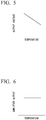
FIG. 6 is a graph showing the relationship between the temperature of the sensor output device and the voltage level of the output signal. -
FIG. 7 is a block diagram showing a sensor output device according to a second embodiment of the present invention. -
FIG. 8 is a graph showing the relationship between the temperature and amplifier gain of the sensor output circuit of the sensor output device shown inFIG. 7 . -
FIG. 9 is a graph showing the relationship between the temperature of the sensor output device shown inFIG. 7 and the voltage level of the output signal. -
FIG. 10 is a block diagram of a sound output device for an acoustic guitar according to a third embodiment of the present invention. - A
sensor output device 100 according to a first embodiment of the present invention will be described in detail hereinbelow, referring toFIG. 1 to FIG. 6 . In order to make the drawings easy to comprehend, the thickness and dimension ratio of each constitutional element have been suitably adjusted. -
FIG. 1 is a block diagram showing thesensor output device 100. As shown inFIG. 1 , thesensor output device 100 includes asheet sensor 1 and asensor output circuit 2. Thesheet sensor 1 and the sensor output circuit (output circuit) 2 are housed in one case (that is, in the same case). Here,FIG. 10 shows that thesheet sensor 1 and thesensor output circuit 2 are housed in the case of thesensor output device 100. -
FIG. 2 is a side view of thesheet sensor 1 shown inFIG. 1 . The sheet sensor (sensor) 1 is a sensor that includes a sheet-shapedpiezoelectric element 11 containing porous resin. Thepiezoelectric element 11 includes electrode layers 13 (afirst electrode layer 13a and asecond electrode layer 13b) laminated on both sides of anelectretized film 12 as shown inFIG. 2 . - The
electretized film 12 is a sheet-like film containing porous resin. For example, theelectretized film 12 is obtained by the following manner. First, a resin film consisting of an electrolyte layer provided on at least one surface of a porous layer is permeated with a non-reactive gas under a high-pressure condition. Subsequently the resin film is thermally treated under reduced pressure to obtain a porous resin film. The porous resin film is then electretized by a direct-current high-voltage discharge treatment, and thereby theelectretized film 12 is obtained (for example, see Japanese Unexamined Patent Application, First Publication No.2010-89495 - The
electretized film 12 is obtained by electretizing the porous resin film containing a porous layer capable of holding electric charges therein, and can stably hold electric charges for a long period of time. - The
electretized film 12 is known to exhibit a piezoelectric effect and so can be used for vibration measurement, vibration control, sound generation, sound detection, and the like. Therefore, by making use of the light weight, theelectretized film 12 can be used for transducers in audio equipment such as speakers, headphones, microphones and the like and for flexible sheet-shaped pressure sensors. - As shown in
FIG. 2 , theelectrode layer 13 is laminated on both surfaces of theelectretized film 12. Theelectrode layer 13 includes thefirst electrode layer 13a and thesecond electrode layer 13b. Thefirst electrode layer 13a and thesecond electrode layer 13b are connected to respective lead wires (not shown in the figure), with one of the lead wires connected to anoutput terminal 14 and the other to ground. The material for forming thefirst electrode layer 13a and thesecond electrode layer 13b is not particularly limited as long as the material is electrically conductive, and examples thereof include various types of metals such as aluminum and silver, alloys of these metals, carbon and the like. - The
sheet sensor 1 that includes such apiezoelectric element 11 containing porous resin is suited for detection of sound due to being flexible in the thickness direction, and also does not inhibit vibration of a musical instrument owing to the lightweight properties and thinness thereof. Therefore, thesheet sensor 1 is suitably used as a musical instrument pickup that detects both vibration and sound. It is to be noted that the term "sound" as referred to means a compressional wave transmitted through air, and the term "vibration" as referred to means vibration that propagates in a solid to a sensor. -
FIG. 3 is a graph that shows the relationship between the temperature of thesheet sensor 1 and the sensor sensitivity. As shown inFIG. 3 , the sensor sensitivity of thesheet sensor 1 increases as the temperature rises owing to the characteristics of the material, and so the voltage level of the output signal from thesheet sensor 1 increases. The temperature dependence is about +0.2 db/°C. Thesheet sensor 1 has a linear temperature dependence in a range from 0° C to 50° C, which is the use temperature range when thesensor output device 100 is used as a pickup for a musical instrument. - As shown in
FIG. 1 , thesensor output circuit 2 includes anoperational amplifier 21, athermistor 22, afirst resistor 23, asecond resistor 24, and athird resistor 25. Thefirst resistor 23, thesecond resistor 24, and thethird resistor 25 are resistors. In the block diagram shown inFIG. 1 , only major electronic components are shown, while those components such as capacitors and resistors, even though required for electronic circuits, are omitted due to not being directly related to the effect of the present embodiment. - The
thermistor 22 is a resistor that shows a large resistance change with respect to temperature change. Thethermistor 22 is a general thermally sensitive resistor. The type of thethermistor 22 is not particularly limited. Thethermistor 22 may be one having a negative temperature coefficient, for example, an NTC-type thermistor. -
FIG. 4 is a graph showing the relationship between the temperature and the resistance value Rs of thethermistor 22. As shown inFIG. 4 , thethermistor 22 has a resistance temperature characteristic in which the resistance value Rs decreases as the temperature increases. Thethermistor 22 has a linear resistance temperature characteristic in a range of 0° C to 50° C, which is the use temperature range when thesensor output device 100 is used as a musical instrument pickup. - The
thermistor 22 and thefirst resistor 23 form a voltage dividing circuit for dividing the voltage of the electrical signal input from theoutput terminal 14 of thesheet sensor 1. The output voltage Vout of the voltage dividing circuit is determined by the ratio of the resistance value R1 of thefirst resistor 23 and the resistance value Rs of thethermistor 22. Assuming that the input voltage from theoutput terminal 14 of thesheet sensor 1 is Vin, the output voltage Vout of the voltage dividing circuit is (R1/R1 + Rs) × Vin. Even in the absence of thefirst resistor 23, if thethermistor 22 is disposed so as to connect theoutput terminal 14 of thesheet sensor 1 to ground, the above-mentioned voltage dividing circuit functions. -
FIG. 5 is a graph showing the relationship between the temperature of thethermistor 22 and the output voltage of the voltage dividing circuit. As shown inFIG. 4 , as the temperature of thethermistor 22 rises, the resistance value Rs decreases. Therefore, in the case of a constant input voltage, when the temperature rises, the output voltage of the voltage dividing circuit decreases. - The
operational amplifier 21 amplifies the electrical signal input from theoutput terminal 14 of thesheet sensor 1. The electrical signal output from theoutput terminal 14 is connected to the inverting input terminal (-) of theoperational amplifier 21 via the voltage dividing circuit formed by thethermistor 22 and thefirst resistor 23, and via thesecond resistor 24. The non-inverting input terminal (+) of theoperational amplifier 21 is connected to ground. The output signal of theoperational amplifier 21 is connected to the inverting input terminal (-) of theoperational amplifier 21 via a feedback resistor constituted by thethird resistor 25. - The
sensor output circuit 2 thus configured constitutes a so-called inverting amplifier circuit, whereby the input signal is amplified and inverted at the output. Here, thesensor output circuit 2 is not limited to an inverting amplifier circuit. Thesensor output circuit 2 may alternatively have feedback provided by a feedback circuit and be a circuit that simply amplifies the input signal, such as a non-inverting amplifier circuit. - The type of the
operational amplifier 21 is not particularly limited. In order to amplify the input signal from thesheet sensor 1, theoperational amplifier 21 is selected so that the range of the input voltage from thesheet sensor 1 is included in the linear region and not included in the saturation region of theoperational amplifier 21. - Next, the operation when the temperature of the
sensor output device 100 changes will be described. When the temperature rises, the level of the output signal from thesheet sensor 1 rises as shown inFIG. 3 . As a result, the voltage level of the input signal input to the voltage dividing circuit rises. On the other hand, when the temperature rises, the output voltage output from the voltage dividing circuit decreases as shown inFIG. 5 under the condition where the input voltage is held constant. -
FIG. 6 is a graph showing the relationship between the temperature of thesensor output device 100 and the voltage level of the output signal. As shown inFIG. 6 , even when the temperature of thesensor output device 100 rises, leading to an increase in the voltage level of the input signal to thesensor output circuit 2, it is possible to suppress fluctuation of the input voltage to theoperational amplifier 21 and to suppress fluctuation of the voltage level of thesensor output circuit 2 due to the drop of the output voltage by the voltage dividing circuit. - According to the
sensor output device 100 of the present embodiment configured as described above, thesensor output circuit 2 enables temperature compensation for suppressing fluctuation in the output level due to temperature change of thesheet sensor 1 which includes the sheet-likepiezoelectric element 11 containing porous resin. - Further, according to the
sensor output device 100 of the present embodiment, thesensor output circuit 2 can be easily realized simply by adding a simple electrical circuit, and so can be realized at low cost. - The direction of change in characteristics due to temperature is opposite between the temperature characteristic of the sensor sensitivity of the sheet sensor 1 (see
FIG. 3 ) and the temperature characteristic of the voltage dividing circuit formed by the thermistor 22 (seeFIG. 5 ). In particular, in the range of 0° C to 50° C, which is the use temperature range when thesensor output device 100 is used as a pickup for a musical instrument, the temperature characteristic of the sensor sensitivity of the sheet sensor 1 (seeFIG. 3 ) and the temperature characteristic of the voltage dividing circuit formed by the voltage dividing circuit (seeFIG. 5 ) each have a linear temperature characteristic. Therefore, particularly in this operating temperature range, thesensor output circuit 2 even with a simple configuration suitably performs temperature compensation for suppressing fluctuation of the output level due to temperature change of thesheet sensor 1. - Further, according to the
sensor output device 100 of the present embodiment, thesheet sensor 1 and thesensor output circuit 2 are housed in one case, and so the ambient temperature of thesheet sensor 1 and the ambient temperature of thesensor output circuit 2 are equivalent. Therefore, in the aforementioned temperature compensation, it is not necessary to consider the case of the ambient temperatures of the two being different, which simplifies the temperature compensation. - While the first embodiment of the invention has been described in detail heretofore with reference to the drawings, it should be understood that the specific constitutions are not limited to this embodiment and any design changes which do not depart from the scope of the present invention are included in the present invention. Constitutions are also possible in which the constituent elements shown in the aforementioned first embodiment and the modifications described below are suitably combined.
- For example, in the above-described embodiment, the
piezoelectric element 11 is formed by laminating the electrode layers 13 on theelectretized film 12, and theelectretized film 12 is formed by causing a resin film including an electrolyte layer provided on at least one surface of a porous layer to be permeated with a non-reactive gas under high-pressure conditions and subsequently thermally treated under reduced pressure to obtain a porous resin film, which is then electretized upon being subjected to a direct-current high-voltage discharge treatment. However, the type of the piezoelectric element is not limited thereto. The piezoelectric element may be a porous resin film including a porous layer capable of holding charges and thereby exhibiting a piezoelectric effect. Further, the shape of the piezoelectric element is not limited to a sheet-like shape, and may, for example, have a block shape. - Hereinbelow, a
sensor output device 100B according to a second embodiment of the present invention will be described with reference toFIGS. 7 to 9 . In order to make the drawings easy to comprehend, the thickness and dimension ratio of each constitutional element have been suitably adjusted. The same reference numerals will be used to refer to components identical to those already described, with redundant descriptions being omitted. -
FIG. 7 is a block diagram showing thesensor output device 100B. As shown inFIG. 7 , thesensor output device 100B includes asheet sensor 1 and a sensor output circuit (output circuit) 2B. Thesheet sensor 1 and thesensor output circuit 2B are housed in one case. - As shown in
FIG. 7 , thesensor output circuit 2B includes anoperational amplifier 21, athermistor 22B, asecond resistor 24, and athird resistor 25. Thesecond resistor 24 and thethird resistor 25 are resistors. In the block diagram shown inFIG. 7 , only major electronic components are shown, while those components such as capacitors and resistors, even though required for electronic circuits, are omitted due to not being directly related to the effect of the present embodiment. - The
operational amplifier 21 amplifies the electrical signal input from anoutput terminal 14 of thesheet sensor 1. The electrical signal output from theoutput terminal 14 is connected to the inverting input terminal (-) of theoperational amplifier 21 via thesecond resistor 24. The non-inverting input terminal (+) of theoperational amplifier 21 is connected to ground. The output signal of theoperational amplifier 21 is connected to the inverting input terminal (-) of theoperational amplifier 21 via a feedback circuit constituted by thethermistor 22B and thethird resistor 25. - The
sensor output circuit 2B thus configured constitutes a so-called inverting amplifier circuit, whereby the input signal is amplified and inverted at the output. Here, thesensor output circuit 2B is not limited to an inverting amplifier circuit. Thesensor output circuit 2B may alternatively have feedback provided by a feedback circuit and be a circuit that simply amplifies the input signal, such as a non-inverting amplifier circuit. - The type of
operational amplifier 21 is not particularly limited. In order to amplify the input signal from thesheet sensor 1, theoperational amplifier 21 is selected so that the range of the input voltage from thesheet sensor 1 is included in the linear region and not the saturation region of theoperational amplifier 21. - Similarly to the
thermistor 22, thethermistor 22B is a resistor that shows a large resistance change with respect to temperature change. Thethermistor 22B is a general thermally sensitive resistor. The type of thethermistor 22B is not particularly limited. Thethermistor 22B may be one having a negative temperature coefficient, for example, an NTC-type thermistor. - The
thermistor 22B and thethird resistor 25 constitute a feedback circuit of theoperational amplifier 21. Since thethermistor 22B and thethird resistor 25 are connected in series, the resistance value Rf of the feedback circuit is a value obtained by adding the resistance value Rs of thethermistor 22 and the resistance value R2 of thethird resistor 25. -
FIG. 8 is a graph showing the relationship between the temperature of thesensor output circuit 2B and the amplifier gain when the input signal level is constant. Thesensor output circuit 2B is an inverting amplifier circuit. The amplification factor of the output signal of thesensor output circuit 2B is determined by the ratio (Rf/R2) of the resistance value Rf of the feedback circuit to the resistance value R2 of thesecond resistor 24. When the temperature rises, as shown inFIG. 4 , the resistance value Rs of thethermistor 22B decreases and so the resistance value Rf of the feedback circuit also decreases. For that reason, as shown inFIG. 8 , the amplifier gain of thesensor output circuit 2B also decreases. - Note that the configuration of the feedback circuit is not limited to the configuration of the
thermistor 22B and thethird resistor 25 connected in series. Any configuration of the feedback circuit is possible as long as the resistance value thereof decreases as the temperature rises. For example, thethermistor 22B and thethird resistor 25 may be connected in parallel. - Next, the operation when the temperature of the
sensor output device 100B changes will be described. When the temperature rises, the level of the output signal from thesheet sensor 1 rises as shown inFIG. 3 . As a result, the voltage level of the input signal inputted to thesensor output circuit 2B rises. On the other hand, when the temperature rises, the amplifier gain of thesensor output circuit 2B decreases as shown inFIG. 8 . -
FIG. 9 is a graph showing the relationship between the temperature of thesensor output device 100B and the voltage level of the output signal. Even when the temperature of thesensor output device 100B rises and the voltage level of the input signal to thesensor output circuit 2B rises, as shown inFIG. 9 , it is possible to suppress fluctuation of the voltage level of thesensor output circuit 2B due to the drop in the amplifier gain of thesensor output circuit 2B. - According to the
sensor output device 100B of the present embodiment configured as described above, thesensor output circuit 2B enables temperature compensation for suppressing fluctuation in the output level due to temperature change of thesheet sensor 1 that includes the sheet-likepiezoelectric element 11 containing porous resin. - Further, according to the
sensor output device 100B of the present embodiment, thesensor output circuit 2 can be easily realized simply by adding a simple electrical circuit, and so can be realized at low cost. - The direction of change in characteristics due to temperature is opposite between the temperature characteristic of the sensor sensitivity of the sheet sensor 1 (see
FIG. 3 ) and the temperature characteristic of the amplifier gain of thesensor output circuit 2B (seeFIG. 8 ). In particular, in the range of 0° C to 50° C, which is the use temperature range when thesensor output device 100B is used as a pickup for a musical instrument, the temperature characteristic of the sensor sensitivity of the sheet sensor 1 (seeFIG. 3 ) and the temperature characteristic of the amplifier gain of thesensor output circuit 2B (seeFIG. 8 ) have a linear temperature characteristic. Therefore, particularly in this operating temperature range, thesensor output circuit 2B even with a simple configuration suitably performs temperature compensation for suppressing fluctuation of the output level due to temperature change of thesheet sensor 1. - Further, according to the
sensor output device 100B of the present embodiment, thesheet sensor 1 and thesensor output circuit 2B are stored in one case, and so the ambient temperature of thesheet sensor 1 and the ambient temperature of thesensor output circuit 2B are equal to each other. Therefore, in the aforementioned temperature compensation, it is not necessary to consider the case of the ambient temperatures of the two being different, which simplifies the temperature compensation. - A third embodiment of the present invention will be described with reference to
FIG. 10 . Asound output device 200 for an acoustic guitar according to the third embodiment of the present invention includes thesensor output device 100. In the following description, the same reference numerals will be used to refer to components identical to those already described, with redundant descriptions being omitted. -
FIG. 10 is a block diagram of asound output device 200 for an acoustic guitar. As shown inFIG. 10 , thesound output device 200 includes thesensor output device 100, a piezosensor output device 300, and asignal processing unit 400. - The
sheet sensor 1 is attached to a part functioning as the soundboard of the body of an acoustic guitar and is used as an acoustic guitar pickup for detecting vibration. - The piezo sensor output device (second sensor output device) 300 includes a
piezo sensor 3 and a piezo sensor output circuit 4. - The piezo sensor (second sensor) 3 is a sensor that includes a piezo element for converting vibration into an electrical signal. The
piezo sensor 3 can convert physical vibration of the soundboard or the like directly into a sound signal by means of a piezo element in which an electric current is generated by application of pressure. - Like the
sheet sensor 1, thepiezo sensor 3 is also attached to a part functioning as the soundboard in the acoustic guitar body and is used as an acoustic guitar pickup for detecting vibration. - The piezo sensor output circuit (second sensor output circuit) 4 is an output circuit having, for example, an operational amplifier for amplifying the weak output signal of the
piezo sensor 3. Thepiezo sensor 3 has a lower temperature dependence than thesheet sensor 1, so no particular temperature compensation is necessary for the piezo sensor output circuit 4. - The
signal processing unit 400 receives the output of thesensor output device 100 and the output of the piezosensor output device 300, converts the output signals from the two sensors into sound signals by signal processing, adjusts (mixes) the levels of the sound signals, and then outputs the final sound signal. Thesignal processing unit 400 can also add sound effects to the acoustic signal if necessary. - The
signal processing unit 400 may be constituted with a computer including a CPU and memory and be capable of executing a program, and a part or all of thesignal processing unit 400 may be constituted with dedicated hardware such as a digital signal processor. - Next, the operation of the
sound output device 200 for an acoustic guitar will be described. When a performer plays the acoustic guitar, thesheet sensor 1 and thepiezo sensor 3 attached to the soundboard of the body of the acoustic guitar detect the vibration of the soundboard of the body of the acoustic guitar. Thesensor output circuit 2 and the piezo sensor output circuit 4 output the output signals of the respective sensors to thesignal processing unit 400. Thesignal processing unit 400 adjusts the levels of the sound signals and outputs the final sound signal. - When the ambient temperature of the acoustic guitar and the
sound output device 200 rises due to the acoustic guitarsound output device 200 being illuminated by stage lighting or the like, temperature compensation is required for the output signal from theseat sensor 1. This is because the sensor sensitivity of thesheet sensor 1 increases as the temperature rises as shown inFIG. 3 , and the voltage level of the output signal from theseat sensor 1 rises. On the other hand, the temperature dependence of thepiezo sensor 3 is low compared to thesheet sensor 1, and so in such a situation temperature compensation is not necessary for the output signal from thepiezo sensor 3. - Originally, when the output of the
sensor output device 100 and the output of the piezosensor output device 300 are input to thesignal processing unit 400 without temperature compensation, thesignal processing unit 400 needs to adjust the level of each sound signals in consideration of the temperature dependence of each sensor. However, due to the temperature compensation function of thesensor output circuit 2, fluctuation of the output level due to temperature change of thesheet sensor 1 can be favorably suppressed. Therefore, thesignal processing unit 400 can adjust the level of the sound signal acquired from each sensor without considering temperature dependence. - According to the
sound output device 200 of the present embodiment configured as described above, temperature compensation is performed for the output circuit of the sensor in which temperature compensation is required (for example, sheet sensor 1). Therefore, even when a plurality of sensors (sheet sensor 1 and piezo sensor 3) have different temperature characteristics, it is not necessary to consider temperature compensation when adjusting the levels of the sound signals. - According to the
sound output device 200 of the present embodiment, in the range of 0° C to 50° C, which is the use temperature range when thesensor output device 100 is used as an acoustic guitar pickup, similarly to the first embodiment, temperature compensation for suppressing fluctuation of the output level due to the temperature change of thesheet sensor 1 can be suitably performed with an inexpensive and simple electrical circuit. - While a third embodiment of the invention has been described in detail heretofore with reference to the drawings, it should be understood that the specific constitutions are not limited to this embodiment and any design changes not departing from the scope of the present invention are included in the present invention. Constitutions are also possible in which the constituent elements shown in the aforementioned third embodiment and the modifications described below are suitably combined.
- For example, in the above-described embodiment, the
sound output device 200 is attached to an acoustic guitar and used as a pickup, but the musical instrument to which thesound output device 200 is mounted is not limited to an acoustic guitar. Thesound output device 200 can be attached to a musical instrument that converts vibration to sound, such as a marimba or the like. - In the above embodiment, the second sensor used together with the sheet sensor is the
piezo sensor 3, but the type of the second sensor is not limited thereto. The second sensor may be a sensor that can be used as a pickup for a musical instrument. - In the above embodiment, temperature compensation is performed by providing the
thermistor 22 in thesensor output circuit 2, but the method of temperature compensation is not limited thereto. An element or a sensor capable of detecting a temperature change such as a thermistor or the like may be provided in a case with the sheet sensor, and a signal processing device, upon detecting a temperature change, may apply signal processing corresponding to the temperature compensation of the sheet sensor. In addition, if such processing is enabled as an auxiliary function of the sound output device of the above embodiment, temperature compensation of the sheet sensor can be more reliably performed. - In the above embodiment, the acoustic guitar (musical instrument) includes the
sheet sensor 1 and thepiezo sensor 3, but the type of the sensors mounted on the acoustic guitar (musical instrument) is not limited thereto. The acoustic guitar (musical instrument) may include only thesheet sensor 1, or may include another sensor besides thesheet sensor 1 and thepiezo sensor 3. - While preferred embodiments of the invention have been described and illustrated above, it should be understood that these are exemplary of the invention and are not to be considered as limiting. Additions, omissions, substitutions, and other modifications can be made without departing from the spirit or scope of the present invention. In addition, the constituent elements shown in the embodiments and the modifications described below can be combined appropriately. Accordingly, the invention is not to be considered as being limited by the foregoing description, and is only limited by the scope of the appended claims.
Claims (10)
- A sensor output device comprising:a sensor that comprises a piezoelectric element and an output terminal, the piezoelectric element comprising porous resin; andan output circuit that comprises a thermistor, the thermistor connecting the output terminal of the sensor to ground.
- The sensor output device according to claim 1, wherein the output circuit further comprises a resistor between the output terminal of the sensor and the thermistor.
- A sensor output device comprising:a sensor that comprises a piezoelectric element that comprises porous resin; andan output circuit that is connected with the sensor, the output circuit comprising an operational amplifier and a feedback circuit, the feedback circuit comprising a thermistor connected with the operational amplifier.
- The sensor output device according to claim 3,
wherein the operational amplifier comprises an inverting input terminal and an output terminal, and
the feedback circuit is connected with the inverting input terminal of the operational amplifier and the output terminal of the operational amplifier. - The sensor output device according to claim 3 or 4, wherein the feedback circuit further comprises a resistor connected in series with the thermistor.
- The sensor output device according to any one of claims 1 to 5, wherein the sensor and the output circuit are housed in one case.
- The sensor output device according to any one of claims 1 to 6,
wherein a sensitivity of the sensor increases as temperature of the sensor rises in a certain temperature range, and
a resistance value of the thermistor increase as temperature of the thermistor rises in the certain temperature range. - A sound output device comprising:the sensor output device according to any one of claims 1 to 7;a second sensor output device that comprises a second sensor and a second sensor output circuit a second sensor that is connected with the second sensor; anda signal processing unit that processes an output signal of the sensor output device and an output signal of the second sensor output device.
- A musical instrument comprising the sensor output device according to any one of claims 1 to 6.
- A musical instrument comprising the sound output device according to claim 8.
Applications Claiming Priority (1)
| Application Number | Priority Date | Filing Date | Title |
|---|---|---|---|
| JP2017214942A JP6665847B2 (en) | 2017-11-07 | 2017-11-07 | Sensor output device, sound output device and musical instrument |
Publications (2)
| Publication Number | Publication Date |
|---|---|
| EP3480569A1 true EP3480569A1 (en) | 2019-05-08 |
| EP3480569B1 EP3480569B1 (en) | 2025-09-17 |
Family
ID=64172355
Family Applications (1)
| Application Number | Title | Priority Date | Filing Date |
|---|---|---|---|
| EP18204313.3A Active EP3480569B1 (en) | 2017-11-07 | 2018-11-05 | Sound output device and musical instrument |
Country Status (4)
| Country | Link |
|---|---|
| US (1) | US10659888B2 (en) |
| EP (1) | EP3480569B1 (en) |
| JP (1) | JP6665847B2 (en) |
| CN (1) | CN109756819B (en) |
Families Citing this family (2)
| Publication number | Priority date | Publication date | Assignee | Title |
|---|---|---|---|---|
| CN110719556A (en) * | 2019-10-24 | 2020-01-21 | 朝阳聚声泰(信丰)科技有限公司 | Low-temperature protection MEMS microphone and circuit diagram thereof |
| WO2022264641A1 (en) * | 2021-06-17 | 2022-12-22 | 株式会社村田製作所 | Sensor and sensor processing device |
Citations (8)
| Publication number | Priority date | Publication date | Assignee | Title |
|---|---|---|---|---|
| JPS5584684U (en) * | 1978-12-08 | 1980-06-11 | ||
| JPH0829181A (en) * | 1994-07-20 | 1996-02-02 | Akai Electric Co Ltd | Vibration control apparatus |
| JP2006119035A (en) * | 2004-10-22 | 2006-05-11 | Nissan Motor Co Ltd | Knocking sensor and knocking detection device |
| JP2010089495A (en) | 2008-09-12 | 2010-04-22 | Yupo Corp | Electret-converted film |
| WO2011111125A1 (en) * | 2010-03-12 | 2011-09-15 | パナソニック株式会社 | Signal processing device and digital output microphone unit |
| US20110248935A1 (en) * | 2010-04-08 | 2011-10-13 | Nokia Corporation | Apparatus and method for sound reproduction |
| WO2017056819A1 (en) * | 2015-09-30 | 2017-04-06 | ヤマハ株式会社 | Sensor unit and musical instrument |
| JP2017158419A (en) * | 2016-03-01 | 2017-09-07 | ヤマハ株式会社 | Vibration control device |
Family Cites Families (16)
| Publication number | Priority date | Publication date | Assignee | Title |
|---|---|---|---|---|
| JPS6396485U (en) * | 1986-12-11 | 1988-06-22 | ||
| JPH01136429U (en) * | 1988-03-10 | 1989-09-19 | ||
| JP2006064594A (en) | 2004-08-27 | 2006-03-09 | Aisin Seiki Co Ltd | Pinch detection device |
| WO2008106555A2 (en) * | 2007-02-27 | 2008-09-04 | Iptrade, Inc. | Piezoelectric package with improved lead structure |
| JP5236890B2 (en) * | 2007-04-03 | 2013-07-17 | 株式会社アコー | Microphone unit, sound level meter and sound calibrator |
| JP2009139730A (en) * | 2007-12-07 | 2009-06-25 | Yamaha Corp | Musical signal output device and string musical instrument |
| JP6308130B2 (en) * | 2012-07-23 | 2018-04-11 | ヤマハ株式会社 | Temperature measuring device and protection device for acoustic signal converter |
| US9202453B2 (en) * | 2012-12-05 | 2015-12-01 | Bose Corporation | Asymmetric temperature compensation of microphone sensitivity at an active noise reduction system |
| AU2013203955A1 (en) * | 2013-04-11 | 2014-10-30 | David John ULBRICK | Noise reduction device |
| US20140348339A1 (en) * | 2013-05-24 | 2014-11-27 | Transcend Information, Inc. | Earphone System and Related Method of Temporarily Increasing Volume |
| JP2014231933A (en) * | 2013-05-28 | 2014-12-11 | パナソニック株式会社 | Cooling control circuit and electrostatic atomizer comprising the same |
| WO2014192301A1 (en) * | 2013-05-30 | 2014-12-04 | 京セラ株式会社 | Unit, electronic device, and method for manufacturing electronic device |
| US9401134B2 (en) * | 2013-08-02 | 2016-07-26 | Donald L. Baker | Acoustic-electric stringed instrument with improved body, electric pickup placement, pickup switching and electronic circuit |
| TWI584656B (en) * | 2015-11-03 | 2017-05-21 | 華碩電腦股份有限公司 | Thermal protecting device of speaker |
| DE102017104434B3 (en) * | 2017-03-03 | 2018-07-12 | Infineon Technologies Ag | Device and method for determining a temperature or a temperature-dependent value usable for determining the temperature, temperature sensor, pressure sensor and combination sensor |
| US10477298B2 (en) * | 2017-09-08 | 2019-11-12 | Immersion Corporation | Rendering haptics on headphones with non-audio data |
-
2017
- 2017-11-07 JP JP2017214942A patent/JP6665847B2/en active Active
-
2018
- 2018-11-02 CN CN201811300893.6A patent/CN109756819B/en active Active
- 2018-11-05 EP EP18204313.3A patent/EP3480569B1/en active Active
- 2018-11-06 US US16/182,028 patent/US10659888B2/en active Active
Patent Citations (8)
| Publication number | Priority date | Publication date | Assignee | Title |
|---|---|---|---|---|
| JPS5584684U (en) * | 1978-12-08 | 1980-06-11 | ||
| JPH0829181A (en) * | 1994-07-20 | 1996-02-02 | Akai Electric Co Ltd | Vibration control apparatus |
| JP2006119035A (en) * | 2004-10-22 | 2006-05-11 | Nissan Motor Co Ltd | Knocking sensor and knocking detection device |
| JP2010089495A (en) | 2008-09-12 | 2010-04-22 | Yupo Corp | Electret-converted film |
| WO2011111125A1 (en) * | 2010-03-12 | 2011-09-15 | パナソニック株式会社 | Signal processing device and digital output microphone unit |
| US20110248935A1 (en) * | 2010-04-08 | 2011-10-13 | Nokia Corporation | Apparatus and method for sound reproduction |
| WO2017056819A1 (en) * | 2015-09-30 | 2017-04-06 | ヤマハ株式会社 | Sensor unit and musical instrument |
| JP2017158419A (en) * | 2016-03-01 | 2017-09-07 | ヤマハ株式会社 | Vibration control device |
Also Published As
| Publication number | Publication date |
|---|---|
| US10659888B2 (en) | 2020-05-19 |
| CN109756819A (en) | 2019-05-14 |
| JP2019087886A (en) | 2019-06-06 |
| EP3480569B1 (en) | 2025-09-17 |
| CN109756819B (en) | 2020-10-09 |
| US20190141455A1 (en) | 2019-05-09 |
| JP6665847B2 (en) | 2020-03-13 |
Similar Documents
| Publication | Publication Date | Title |
|---|---|---|
| CN102804807B (en) | Electronic equipment, electronic installation, mobile terminal apparatus and the method for the treatment of electronic signal | |
| EP2304872B1 (en) | Circuit for amplifying a signal representing a variation in resistance of a variable resistance and corresponding capacitor | |
| CN110291718B (en) | System and method for calibrating microphone cutoff frequency | |
| JP2008256433A (en) | Microphone unit, sound level meter and sound calibrator | |
| US8170238B2 (en) | Integrated circuit attached to microphone | |
| US11476805B2 (en) | Amplifier systems | |
| JP2012090224A (en) | Microphone unit | |
| US10834504B2 (en) | Temperature detecting and controlling integration device and the temperature controlling method applied for micro speaker | |
| US10080082B2 (en) | Microphone system having high acoustical overload point | |
| US10659888B2 (en) | Sensor output device, sound output device, and musical instrument | |
| EP3911926A1 (en) | Infrasound detector | |
| WO2015111380A1 (en) | Fuel-pressure sensor with built-in charge amplifier | |
| WO2011111125A1 (en) | Signal processing device and digital output microphone unit | |
| JP2003075481A (en) | Impedance detection circuit and capacitance detection circuit | |
| US20180146286A1 (en) | Phase correcting system and a phase correctable transducer system | |
| CN110545503A (en) | Signal transmission circuit and signal transmission method | |
| JP4893053B2 (en) | Physical quantity detection device | |
| WO2020059246A1 (en) | Sensor processing circuit and sensor system | |
| EP4354728A1 (en) | Preamplifier for capacitator microphone operating in the infrasonic frequency range | |
| US11949382B2 (en) | Amplifier systems | |
| Frederiksen | Condenser microphones | |
| US20230303388A1 (en) | Mems microphone | |
| US20100158277A1 (en) | Read-out circuit with high input impedance | |
| JP2006078310A (en) | Semiconductor sensor apparatus | |
| WO2022264641A1 (en) | Sensor and sensor processing device |
Legal Events
| Date | Code | Title | Description |
|---|---|---|---|
| PUAI | Public reference made under article 153(3) epc to a published international application that has entered the european phase |
Free format text: ORIGINAL CODE: 0009012 |
|
| STAA | Information on the status of an ep patent application or granted ep patent |
Free format text: STATUS: THE APPLICATION HAS BEEN PUBLISHED |
|
| AK | Designated contracting states |
Kind code of ref document: A1 Designated state(s): AL AT BE BG CH CY CZ DE DK EE ES FI FR GB GR HR HU IE IS IT LI LT LU LV MC MK MT NL NO PL PT RO RS SE SI SK SM TR |
|
| AX | Request for extension of the european patent |
Extension state: BA ME |
|
| STAA | Information on the status of an ep patent application or granted ep patent |
Free format text: STATUS: REQUEST FOR EXAMINATION WAS MADE |
|
| 17P | Request for examination filed |
Effective date: 20191105 |
|
| RBV | Designated contracting states (corrected) |
Designated state(s): AL AT BE BG CH CY CZ DE DK EE ES FI FR GB GR HR HU IE IS IT LI LT LU LV MC MK MT NL NO PL PT RO RS SE SI SK SM TR |
|
| STAA | Information on the status of an ep patent application or granted ep patent |
Free format text: STATUS: EXAMINATION IS IN PROGRESS |
|
| 17Q | First examination report despatched |
Effective date: 20201119 |
|
| REG | Reference to a national code |
Ref country code: DE Ref legal event code: R079 Free format text: PREVIOUS MAIN CLASS: G01H0011080000 Ipc: G10H0003140000 Ref document number: 602018085640 Country of ref document: DE |
|
| GRAP | Despatch of communication of intention to grant a patent |
Free format text: ORIGINAL CODE: EPIDOSNIGR1 |
|
| STAA | Information on the status of an ep patent application or granted ep patent |
Free format text: STATUS: GRANT OF PATENT IS INTENDED |
|
| RIC1 | Information provided on ipc code assigned before grant |
Ipc: H04R 3/00 20060101ALI20250508BHEP Ipc: H04R 17/00 20060101ALI20250508BHEP Ipc: G01H 11/08 20060101ALI20250508BHEP Ipc: H10N 30/857 20230101ALI20250508BHEP Ipc: H10N 30/80 20230101ALI20250508BHEP Ipc: H10N 30/30 20230101ALI20250508BHEP Ipc: H04R 19/01 20060101ALI20250508BHEP Ipc: G10H 3/14 20060101AFI20250508BHEP |
|
| INTG | Intention to grant announced |
Effective date: 20250521 |
|
| GRAS | Grant fee paid |
Free format text: ORIGINAL CODE: EPIDOSNIGR3 |
|
| GRAA | (expected) grant |
Free format text: ORIGINAL CODE: 0009210 |
|
| STAA | Information on the status of an ep patent application or granted ep patent |
Free format text: STATUS: THE PATENT HAS BEEN GRANTED |
|
| AK | Designated contracting states |
Kind code of ref document: B1 Designated state(s): AL AT BE BG CH CY CZ DE DK EE ES FI FR GB GR HR HU IE IS IT LI LT LU LV MC MK MT NL NO PL PT RO RS SE SI SK SM TR |
|
| REG | Reference to a national code |
Ref country code: GB Ref legal event code: FG4D |
|
| REG | Reference to a national code |
Ref country code: CH Ref legal event code: EP |
|
| REG | Reference to a national code |
Ref country code: DE Ref legal event code: R096 Ref document number: 602018085640 Country of ref document: DE |
|
| REG | Reference to a national code |
Ref country code: IE Ref legal event code: FG4D |
|
| PGFP | Annual fee paid to national office [announced via postgrant information from national office to epo] |
Ref country code: DE Payment date: 20251124 Year of fee payment: 8 |
|
| PG25 | Lapsed in a contracting state [announced via postgrant information from national office to epo] |
Ref country code: NO Free format text: LAPSE BECAUSE OF FAILURE TO SUBMIT A TRANSLATION OF THE DESCRIPTION OR TO PAY THE FEE WITHIN THE PRESCRIBED TIME-LIMIT Effective date: 20251217 |
|
| REG | Reference to a national code |
Ref country code: LT Ref legal event code: MG9D |
|
| PG25 | Lapsed in a contracting state [announced via postgrant information from national office to epo] |
Ref country code: FI Free format text: LAPSE BECAUSE OF FAILURE TO SUBMIT A TRANSLATION OF THE DESCRIPTION OR TO PAY THE FEE WITHIN THE PRESCRIBED TIME-LIMIT Effective date: 20250917 |
|
| PG25 | Lapsed in a contracting state [announced via postgrant information from national office to epo] |
Ref country code: HR Free format text: LAPSE BECAUSE OF FAILURE TO SUBMIT A TRANSLATION OF THE DESCRIPTION OR TO PAY THE FEE WITHIN THE PRESCRIBED TIME-LIMIT Effective date: 20250917 |
|
| PG25 | Lapsed in a contracting state [announced via postgrant information from national office to epo] |
Ref country code: GR Free format text: LAPSE BECAUSE OF FAILURE TO SUBMIT A TRANSLATION OF THE DESCRIPTION OR TO PAY THE FEE WITHIN THE PRESCRIBED TIME-LIMIT Effective date: 20251218 |
|
| PG25 | Lapsed in a contracting state [announced via postgrant information from national office to epo] |
Ref country code: SE Free format text: LAPSE BECAUSE OF FAILURE TO SUBMIT A TRANSLATION OF THE DESCRIPTION OR TO PAY THE FEE WITHIN THE PRESCRIBED TIME-LIMIT Effective date: 20250917 |
|
| REG | Reference to a national code |
Ref country code: NL Ref legal event code: MP Effective date: 20250917 |
|
| PG25 | Lapsed in a contracting state [announced via postgrant information from national office to epo] |
Ref country code: LV Free format text: LAPSE BECAUSE OF FAILURE TO SUBMIT A TRANSLATION OF THE DESCRIPTION OR TO PAY THE FEE WITHIN THE PRESCRIBED TIME-LIMIT Effective date: 20250917 |
|
| PG25 | Lapsed in a contracting state [announced via postgrant information from national office to epo] |
Ref country code: BG Free format text: LAPSE BECAUSE OF FAILURE TO SUBMIT A TRANSLATION OF THE DESCRIPTION OR TO PAY THE FEE WITHIN THE PRESCRIBED TIME-LIMIT Effective date: 20250917 |
|
| PG25 | Lapsed in a contracting state [announced via postgrant information from national office to epo] |
Ref country code: RS Free format text: LAPSE BECAUSE OF FAILURE TO SUBMIT A TRANSLATION OF THE DESCRIPTION OR TO PAY THE FEE WITHIN THE PRESCRIBED TIME-LIMIT Effective date: 20251217 |
|
| PG25 | Lapsed in a contracting state [announced via postgrant information from national office to epo] |
Ref country code: NL Free format text: LAPSE BECAUSE OF FAILURE TO SUBMIT A TRANSLATION OF THE DESCRIPTION OR TO PAY THE FEE WITHIN THE PRESCRIBED TIME-LIMIT Effective date: 20250917 |
|
| REG | Reference to a national code |
Ref country code: AT Ref legal event code: MK05 Ref document number: 1839075 Country of ref document: AT Kind code of ref document: T Effective date: 20250917 |
|
| PG25 | Lapsed in a contracting state [announced via postgrant information from national office to epo] |
Ref country code: SM Free format text: LAPSE BECAUSE OF FAILURE TO SUBMIT A TRANSLATION OF THE DESCRIPTION OR TO PAY THE FEE WITHIN THE PRESCRIBED TIME-LIMIT Effective date: 20250917 |
|
| PG25 | Lapsed in a contracting state [announced via postgrant information from national office to epo] |
Ref country code: ES Free format text: LAPSE BECAUSE OF FAILURE TO SUBMIT A TRANSLATION OF THE DESCRIPTION OR TO PAY THE FEE WITHIN THE PRESCRIBED TIME-LIMIT Effective date: 20250917 |
|
| PG25 | Lapsed in a contracting state [announced via postgrant information from national office to epo] |
Ref country code: AT Free format text: LAPSE BECAUSE OF FAILURE TO SUBMIT A TRANSLATION OF THE DESCRIPTION OR TO PAY THE FEE WITHIN THE PRESCRIBED TIME-LIMIT Effective date: 20250917 |
|
| PG25 | Lapsed in a contracting state [announced via postgrant information from national office to epo] |
Ref country code: IT Free format text: LAPSE BECAUSE OF FAILURE TO SUBMIT A TRANSLATION OF THE DESCRIPTION OR TO PAY THE FEE WITHIN THE PRESCRIBED TIME-LIMIT Effective date: 20250917 Ref country code: RO Free format text: LAPSE BECAUSE OF FAILURE TO SUBMIT A TRANSLATION OF THE DESCRIPTION OR TO PAY THE FEE WITHIN THE PRESCRIBED TIME-LIMIT Effective date: 20250917 |
|
| PG25 | Lapsed in a contracting state [announced via postgrant information from national office to epo] |
Ref country code: IS Free format text: LAPSE BECAUSE OF FAILURE TO SUBMIT A TRANSLATION OF THE DESCRIPTION OR TO PAY THE FEE WITHIN THE PRESCRIBED TIME-LIMIT Effective date: 20260117 |
|
| PG25 | Lapsed in a contracting state [announced via postgrant information from national office to epo] |
Ref country code: PT Free format text: LAPSE BECAUSE OF FAILURE TO SUBMIT A TRANSLATION OF THE DESCRIPTION OR TO PAY THE FEE WITHIN THE PRESCRIBED TIME-LIMIT Effective date: 20260119 Ref country code: CZ Free format text: LAPSE BECAUSE OF FAILURE TO SUBMIT A TRANSLATION OF THE DESCRIPTION OR TO PAY THE FEE WITHIN THE PRESCRIBED TIME-LIMIT Effective date: 20250917 |
|
| PG25 | Lapsed in a contracting state [announced via postgrant information from national office to epo] |
Ref country code: PL Free format text: LAPSE BECAUSE OF FAILURE TO SUBMIT A TRANSLATION OF THE DESCRIPTION OR TO PAY THE FEE WITHIN THE PRESCRIBED TIME-LIMIT Effective date: 20250917 |
|
| PG25 | Lapsed in a contracting state [announced via postgrant information from national office to epo] |
Ref country code: EE Free format text: LAPSE BECAUSE OF FAILURE TO SUBMIT A TRANSLATION OF THE DESCRIPTION OR TO PAY THE FEE WITHIN THE PRESCRIBED TIME-LIMIT Effective date: 20250917 Ref country code: SK Free format text: LAPSE BECAUSE OF FAILURE TO SUBMIT A TRANSLATION OF THE DESCRIPTION OR TO PAY THE FEE WITHIN THE PRESCRIBED TIME-LIMIT Effective date: 20250917 |