EP3480474A1 - Bi-directional inline check valve - Google Patents
Bi-directional inline check valve Download PDFInfo
- Publication number
- EP3480474A1 EP3480474A1 EP18202034.7A EP18202034A EP3480474A1 EP 3480474 A1 EP3480474 A1 EP 3480474A1 EP 18202034 A EP18202034 A EP 18202034A EP 3480474 A1 EP3480474 A1 EP 3480474A1
- Authority
- EP
- European Patent Office
- Prior art keywords
- valve
- bore
- head
- extends
- hydraulic system
- Prior art date
- Legal status (The legal status is an assumption and is not a legal conclusion. Google has not performed a legal analysis and makes no representation as to the accuracy of the status listed.)
- Granted
Links
Images


Classifications
-
- F—MECHANICAL ENGINEERING; LIGHTING; HEATING; WEAPONS; BLASTING
- F15—FLUID-PRESSURE ACTUATORS; HYDRAULICS OR PNEUMATICS IN GENERAL
- F15B—SYSTEMS ACTING BY MEANS OF FLUIDS IN GENERAL; FLUID-PRESSURE ACTUATORS, e.g. SERVOMOTORS; DETAILS OF FLUID-PRESSURE SYSTEMS, NOT OTHERWISE PROVIDED FOR
- F15B13/00—Details of servomotor systems ; Valves for servomotor systems
- F15B13/01—Locking-valves or other detent i.e. load-holding devices
-
- F—MECHANICAL ENGINEERING; LIGHTING; HEATING; WEAPONS; BLASTING
- F16—ENGINEERING ELEMENTS AND UNITS; GENERAL MEASURES FOR PRODUCING AND MAINTAINING EFFECTIVE FUNCTIONING OF MACHINES OR INSTALLATIONS; THERMAL INSULATION IN GENERAL
- F16K—VALVES; TAPS; COCKS; ACTUATING-FLOATS; DEVICES FOR VENTING OR AERATING
- F16K15/00—Check valves
- F16K15/02—Check valves with guided rigid valve members
- F16K15/08—Check valves with guided rigid valve members shaped as rings
- F16K15/12—Springs for ring valves
-
- F—MECHANICAL ENGINEERING; LIGHTING; HEATING; WEAPONS; BLASTING
- F15—FLUID-PRESSURE ACTUATORS; HYDRAULICS OR PNEUMATICS IN GENERAL
- F15B—SYSTEMS ACTING BY MEANS OF FLUIDS IN GENERAL; FLUID-PRESSURE ACTUATORS, e.g. SERVOMOTORS; DETAILS OF FLUID-PRESSURE SYSTEMS, NOT OTHERWISE PROVIDED FOR
- F15B13/00—Details of servomotor systems ; Valves for servomotor systems
- F15B13/02—Fluid distribution or supply devices characterised by their adaptation to the control of servomotors
- F15B13/027—Check valves
-
- F—MECHANICAL ENGINEERING; LIGHTING; HEATING; WEAPONS; BLASTING
- F16—ENGINEERING ELEMENTS AND UNITS; GENERAL MEASURES FOR PRODUCING AND MAINTAINING EFFECTIVE FUNCTIONING OF MACHINES OR INSTALLATIONS; THERMAL INSULATION IN GENERAL
- F16K—VALVES; TAPS; COCKS; ACTUATING-FLOATS; DEVICES FOR VENTING OR AERATING
- F16K15/00—Check valves
- F16K15/02—Check valves with guided rigid valve members
- F16K15/021—Check valves with guided rigid valve members the valve member being a movable body around which the medium flows when the valve is open
-
- F—MECHANICAL ENGINEERING; LIGHTING; HEATING; WEAPONS; BLASTING
- F16—ENGINEERING ELEMENTS AND UNITS; GENERAL MEASURES FOR PRODUCING AND MAINTAINING EFFECTIVE FUNCTIONING OF MACHINES OR INSTALLATIONS; THERMAL INSULATION IN GENERAL
- F16K—VALVES; TAPS; COCKS; ACTUATING-FLOATS; DEVICES FOR VENTING OR AERATING
- F16K15/00—Check valves
- F16K15/02—Check valves with guided rigid valve members
- F16K15/025—Check valves with guided rigid valve members the valve being loaded by a spring
-
- F—MECHANICAL ENGINEERING; LIGHTING; HEATING; WEAPONS; BLASTING
- F16—ENGINEERING ELEMENTS AND UNITS; GENERAL MEASURES FOR PRODUCING AND MAINTAINING EFFECTIVE FUNCTIONING OF MACHINES OR INSTALLATIONS; THERMAL INSULATION IN GENERAL
- F16K—VALVES; TAPS; COCKS; ACTUATING-FLOATS; DEVICES FOR VENTING OR AERATING
- F16K15/00—Check valves
- F16K15/18—Check valves with actuating mechanism; Combined check valves and actuated valves
-
- F—MECHANICAL ENGINEERING; LIGHTING; HEATING; WEAPONS; BLASTING
- F15—FLUID-PRESSURE ACTUATORS; HYDRAULICS OR PNEUMATICS IN GENERAL
- F15B—SYSTEMS ACTING BY MEANS OF FLUIDS IN GENERAL; FLUID-PRESSURE ACTUATORS, e.g. SERVOMOTORS; DETAILS OF FLUID-PRESSURE SYSTEMS, NOT OTHERWISE PROVIDED FOR
- F15B15/00—Fluid-actuated devices for displacing a member from one position to another; Gearing associated therewith
- F15B15/20—Other details, e.g. assembly with regulating devices
- F15B15/204—Control means for piston speed or actuating force without external control, e.g. control valve inside the piston
-
- F—MECHANICAL ENGINEERING; LIGHTING; HEATING; WEAPONS; BLASTING
- F15—FLUID-PRESSURE ACTUATORS; HYDRAULICS OR PNEUMATICS IN GENERAL
- F15B—SYSTEMS ACTING BY MEANS OF FLUIDS IN GENERAL; FLUID-PRESSURE ACTUATORS, e.g. SERVOMOTORS; DETAILS OF FLUID-PRESSURE SYSTEMS, NOT OTHERWISE PROVIDED FOR
- F15B2211/00—Circuits for servomotor systems
- F15B2211/40—Flow control
- F15B2211/405—Flow control characterised by the type of flow control means or valve
- F15B2211/40523—Flow control characterised by the type of flow control means or valve with flow dividers
- F15B2211/4053—Flow control characterised by the type of flow control means or valve with flow dividers using valves
-
- Y—GENERAL TAGGING OF NEW TECHNOLOGICAL DEVELOPMENTS; GENERAL TAGGING OF CROSS-SECTIONAL TECHNOLOGIES SPANNING OVER SEVERAL SECTIONS OF THE IPC; TECHNICAL SUBJECTS COVERED BY FORMER USPC CROSS-REFERENCE ART COLLECTIONS [XRACs] AND DIGESTS
- Y10—TECHNICAL SUBJECTS COVERED BY FORMER USPC
- Y10T—TECHNICAL SUBJECTS COVERED BY FORMER US CLASSIFICATION
- Y10T137/00—Fluid handling
- Y10T137/7722—Line condition change responsive valves
- Y10T137/7771—Bi-directional flow valves
- Y10T137/7772—One head and seat carried by head of another
- Y10T137/7777—Both valves spring biased
-
- Y—GENERAL TAGGING OF NEW TECHNOLOGICAL DEVELOPMENTS; GENERAL TAGGING OF CROSS-SECTIONAL TECHNOLOGIES SPANNING OVER SEVERAL SECTIONS OF THE IPC; TECHNICAL SUBJECTS COVERED BY FORMER USPC CROSS-REFERENCE ART COLLECTIONS [XRACs] AND DIGESTS
- Y10—TECHNICAL SUBJECTS COVERED BY FORMER USPC
- Y10T—TECHNICAL SUBJECTS COVERED BY FORMER US CLASSIFICATION
- Y10T137/00—Fluid handling
- Y10T137/7722—Line condition change responsive valves
- Y10T137/7771—Bi-directional flow valves
- Y10T137/778—Axes of ports co-axial
Definitions
- Exemplary embodiments pertain to the art of actuator assemblies.
- a hydraulic actuator may be used to open and close a door or cowl of a gas turbine engine nacelle for ground maintenance purposes.
- the hydraulic actuator may be a single acting hydraulic actuator having an actuating rod.
- a surface irregularity on the bore or potential issues of the sealing may lead to oil leakage due to the intrusion of air into a hydraulic cylinder. Accordingly, it is desirable to provide a check valve capable of inhibiting leakage from the hydraulic cylinder.
- a check valve that includes a housing, a first valve, and a second valve.
- the housing has a first portion that defines a first chamber and a second portion that defines a second chamber.
- the first valve is disposed within and is movable relative to the housing.
- the second valve is at least partially extends into the first valve. Responsive to a fluid flow in a first direction, the second valve and the first valve moves towards a proximal end of the housing and the fluid flow flows around the first valve towards a component.
- the first valve responsive to the fluid flow in a second direction, the first valve moves away from the proximal housing and the second valve moves relative to the first valve to facilitate the fluid flow through the first valve and around the second valve towards a fluid source.
- the first valve includes a valve body having a first head.
- the second valve includes a push rod having a second head that at least partially extends into the first head and a second valve body.
- a retaining member is disposed within the first chamber and defining a first spring seat.
- a first biasing member that extends between the first head and the first spring seat.
- a second biasing member that extends between the second head and the second valve body.
- a hydraulic system that includes an actuator assembly and a check valve.
- the actuator assembly has an actuator body and a piston assembly.
- the actuator body defines an actuator bore and a first bore.
- the piston assembly is disposed within the actuator bore.
- the check valve is connected to the actuator body, an housing, and a first valve.
- the housing has a first portion and a second portion that extends from the first portion and into the first bore.
- the first portion defines a first chamber and the second portion defines a second chamber.
- the first valve includes a valve body that extends through the first chamber and the second chamber and has a first head.
- the actuator body defines a second bore and a transition bore that extends between the first bore and the second bore.
- the first head extends into the transition bore and selectively engages a first valve seat that is defined by the transition bore.
- the first valve further includes a biasing member that extends between the first head and a first spring seat disposed within the first chamber to bias the first head towards engagement with the first valve seat.
- valve body defines a first passage that extends through the valve body.
- the check valve assembly further includes a second valve including a push rod that extends into the second bore, the push rod having a second head that extends into the first passage.
- the second valve further includes a second valve body defining a second passage within which the push rod at least partially extends.
- the first valve further comprising a flow restriction element disposed within the first passage.
- the second valve further includes a second biasing member that extends between the second head and the second valve body to bias the second head towards engagement with the first head.
- the actuator body defines a first port that is fluidly connected to the first bore.
- the actuator body defines a second port that is fluidly connected to the second bore.
- the push rod and the valve body moves toward a proximal end of the housing such that the first head is spaced apart from the first valve seat to facilitate fluid flow through the transition bore and into the first port.
- the fluid flow flows through the second chamber, the first chamber, and through the flow restriction element and the push rod moves relative to the second valve body such that the second head becomes spaced apart from the first head to facilitate the fluid flow to flow between the first head and the second head and through the second port.
- the door opening system is a stand-alone system that is arranged to open and close a door, cowl, or other type of panel of a nacelle of a gas turbine engine to facilitate ground maintenance.
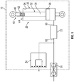
- the hydraulic system 10 includes an actuator assembly 20, a check valve 22, a pressure relief valve 24, and a quick disconnect 26.
- the check valve 22, the pressure relief valve 24, and the quick disconnect 26 may all be integrated with the actuator assembly 20 such that it may be provided as a single actuator unit.
- the actuator assembly 20 may be a hydraulic actuator having an actuator body 30 and a piston assembly 32 that is movably disposed within the actuator body 30.
- the actuator body 30 may define an actuator bore 34 that extends along an axis.
- the piston assembly 32 is movably disposed within the actuator bore 34.
- the piston assembly 32 includes a piston head 36 and a piston rod 38 extending from piston head 36 along the axis.
- the piston rod 38 receives a lost motion device 40 that is located opposite the piston head 36.
- the lost motion device 40 includes a biasing member 42 that is disposed within a cavity 44 that is defined by the piston rod 38 and a connecting member 46 that is at least partially received within the cavity 44 and engages the biasing member 42.
- the connecting member 46 operatively connects the actuator assembly 20 to a door, cowl, or other type of panel to be moved for ground maintenance.
- the actuator body 30 further defines a first bore 50, a second bore 52, and a transition bore 54.
- the first bore 50 extends along an axis 56 that is disposed transverse to the axis along which the actuator bore 34 extends.
- the first bore 50 extends towards the actuator bore 34.
- the first bore 50 has a first bore diameter.
- the second bore 52 extends along the axis 56 and is spaced apart from the first bore 50 by the transition bore 54.
- the second bore 52 has a second bore diameter that is less than the first bore diameter.
- the transition bore 54 extends between the first bore 50 and the second bore 52 along the axis 56.
- the transition bore 54 defines a first valve seat.
- an end wall 58 extends between the first bore 50 and the transition bore 54.
- the end wall 58 is disposed substantially perpendicular to the first bore 50 and the axis 56.
- the actuator body 30 also defines a first port 60 and a second port 62.
- the check valve 22 itself may define the first port 60 and the second port 62.
- the first port 60 is fluidly connected to the first bore 50 and is disposed proximate the end wall 58 and the transition bore 54.
- the first port 60 enables fluid flow into or from the actuator bore 34.
- the second port 62 is fluidly connected to the second bore 52.
- the second port 62 enables fluid flow from a ground service cart to the actuator assembly 20.
- a safety screen or screen element 64 is disposed within the second port 62.
- the check valve 22 is connected to the actuator body 30 and extends into the first bore 50 and the second bore 52.
- the check valve 22 is arranged as a bidirectional check valve that facilitates a fluid flow in at least a first direction and a second direction.
- the check valve 22 includes an end cover or a housing 70, a cap 72, a first valve 74, and a second valve 76.
- the housing 70 is disposed adjacent to the cap 72 and at least partially extends through the cap 72.
- the housing 70 includes a first portion 80 and a second portion 82 that extends between a proximal end 84 of the housing 70 and a distal end 86 of the housing 70 along the axis 56.
- the first portion 80 extends from the proximal end 84 of the housing 70 towards the second portion 82 along the axis 56.
- the first portion 80 is spaced apart from the first bore 50 and defines a first chamber 90.
- the first portion 80 includes a flange 92 that engages an external surface of the actuator body 30.
- the second portion 82 extends from the first portion 80 and extends along the axis 56 towards the distal end 86.
- the second portion 82 extends into the first bore 50 and may sealingly engage the first bore 50.
- the second portion 82 may define a sealing groove that is arranged to receive a seal that engages the first bore 50.
- the second portion 82 defines a second chamber 94.
- At least one of the housing 70 or the first valve 74 is provided with a retaining member 100 that is disposed within the first chamber 90 of the first portion 80 of the housing 70.
- the retaining member 100 defines a central opening through which at least a portion of the first valve 74.
- the retaining member 100 defines a first spring seat 102.
- the cap 72 is disposed within the first bore 50 proximate the distal end 86 of the housing 70 and abuts the end wall 58.
- the cap 72 may be a threaded cap that engages threads that are defined by the first bore 50 proximate the end wall 58 to secure the cap 72 within the first bore 50.
- the cap 72 defines at least one opening that is aligned with the first port 60.
- the first valve 74 is disposed within the housing 70 and is disposed within the first bore 50 and the transition bore 54.
- the first valve 74 includes a valve body 110, a flow restriction element 112, and a first biasing member 114.
- the valve body 110 extends through the first chamber 90 of the first portion 80 and the second chamber 94 of the second portion 82 of the housing 70 along the axis 56.
- the valve body 110 is a generally elongate body that extends between a valve body first end 120 and a valve body second end 122.
- the valve body 110 may have a first body diameter proximate the valve body first end 120 and a second body diameter proximate but spaced apart from the valve body second end 122 that is less than the first body diameter.
- the valve body 110 defines a first passage 124 that extends from the valve body first end 120 to the valve body second end 122.
- a first shoulder 126 is defined within the first passage 124 and is disposed between the valve body first end 120 and the valve body second end 122.
- the valve body 110 includes a first head 130 that is disposed at and extends from the valve body second end 122.
- the first head 130 is spaced apart from the distal end 86 of the housing 70 and extends into the transition bore 54.
- the first head 130 is an enlarged head having a first head diameter that is greater than the first body diameter and the second body diameter.
- the first head 130 includes an aft surface 132, a side surface 134, a tapered surface 136, and a forward surface 138.
- the aft surface 132 faces towards and is disposed substantially parallel to the distal end 86 of the housing 70.
- the aft surface 132 is disposed substantially parallel to the first spring seat 102 of the retaining member 100.
- the side surface 134 extends between the aft surface 132 and the tapered surface 136.
- the side surface 134 is disposed substantially parallel to the first bore 50 and the valve body 110.
- the tapered surface 136 extends between and is disposed in a non-perpendicular and non-parallel relationship with the side surface 134 and the forward surface 138.
- the tapered surface 136 is disposed at an angle that is complementary to first valve seat that is defined by the transition bore 54.
- the tapered surface 136 defines a first seal opening 140 that receives a first sealing member 142.
- the tapered surface 136 and the first sealing member 142 selectively engage the first valve seat that is defined by the transition bore 54.
- the forward surface 138 is disposed generally parallel to the aft surface 132.
- the first head 130 defines a tapered receiving region 144 that extends from the forward surface 138 towards the aft surface 132.
- the tapered receiving region 144 extends to the first passage 124 and defines a second valve seat.
- the second valve seat is arranged as a conical valve seat.
- the flow restriction element 112 is disposed within the first passage 124.
- the flow restriction element 112 engages the first shoulder 126 to seat the flow restriction element 112 within the first passage 124 of the valve body 110.
- the flow restriction element 112 may be a member, such as a disc, that defines at least one orifice sized to restrict flow through the first passage 124.
- the flow restriction element includes two orifices such that the flow restriction element 112 is arranged to inhibit a fluid flow through the first passage 124 when the fluid flow flows in a first direction and facilitate a fluid flow through the first passage 124 when the fluid flow flows in a second direction.
- the first biasing member 114 extends between the first head 130 and the retaining member 100.
- the first biasing member 114 engages the aft surface 132 of the first head 130 and the first spring seat 102 of the retaining member 100 to bias the tapered surface 136 of the first head 130 towards engagement with the first valve seat.
- the second valve 76 is disposed in line with the first valve 74 such that the second valve 76 is at least partially received within the first valve 74.
- the second valve 76 is disposed within the transition bore 54 and the second bore 52.
- the second valve 76 includes a push rod 150, a second valve body 152, and a second biasing member 154.
- the push rod 150 extends between a push rod first end 160 and a push rod second end 162 along the axis 56.
- the push rod second end 162 extends at least partially into the second valve body 152.
- the push rod 150 includes a second head 170 and an extension 172 that is disposed at the push rod second end 162.
- the second head 170 is configured as a tapered head having tapered side surfaces 174.
- the second head 170 is arranged as a conical head that selectively engages the conical valve seat.
- the tapered side surfaces 174 define a second seal opening 176 that receives a second sealing member 178.
- the tapered side surfaces 174 and the second sealing member 178 selectively engage the second valve seat that is defined by the tapered receiving region 144.
- the second head 170 is received by the tapered receiving region 144 of the first head 130.
- the extension 172 extends from the second head 170 and extends into the first passage 124.
- the extension 172 may be configured as a bulbous member that is movably disposed within the first passage 124.
- the second valve body 152 includes an enlarged head 190 and a body 192 that extends from the enlarged head along the axis 56.
- the enlarged head 190 has an enlarged head diameter that is less than the first head diameter.
- the enlarged head 190 defines a second spring seat 194 that is disposed perpendicular to the body 192.
- the second valve body 152 defines a second passage 196 that extends through the enlarged head 190 and the body 192 along the axis 56. A portion of the push rod second end 162 is at least partially received within the second passage 196.
- the second biasing member 154 extends between the second head 170 and the second valve body 152.
- the second biasing member 154 is disposed about the body 192 and engages the second head 170 and the second spring seat 194.
- the second biasing member 154 biases the tapered side surface 174 of the second head 170 towards engagement with the second valve seat that is defined by the tapered receiving region 144 of the first head 130.
- a ground service cart may provide a fluid flow 200 to the hydraulic system 10 through the quick disconnect 26.
- the fluid flow 200 may flow in a first direction through the second port 62, through the screen element 64, and flow into the second bore 52. Should the fluid flow 200 overcome the cracking pressure or the biasing force provided by the first biasing member 114, the valve body 110 of the first valve 74 and the push rod 150 of the second valve 76 both move along the axis 56 towards the proximal end 84 of the housing 70.
- the fluid flow 200 flows into the first port 60 and then flows into the actuator bore 34 to move the piston assembly 32 to stroke the actuator assembly 20.
- the fluid flow 200 may flow in a second direction through the first port 60 and flows into at least one of the second chamber 94 or the first chamber 90 of the housing 70.
- the fluid flow 200 and/or the first biasing member 114 moves the tapered surface 136 of the first head 130 of the valve body 110 of the first valve 74 away from the proximal end 84 of the housing 70 and away from the distal end 86 of the housing 70 towards engagement with the first valve seat that is defined by the transition bore 54.
- the fluid flow 200 flows through at least one of the second chamber 94 or the first chamber 90 and flows through the first passage 124 of the first valve 74 and the flow restriction element 112 enables the fluid flow 200 to flow through the first passage 124 and moves the second head 170 of the second valve 76 relative to the first head 130 of the first valve 74 such that the tapered side surface 174 of the second head 170 of the push rod 150 becomes spaced apart from the second valve seat of the tapered receiving region 144 of the first head 130 of the valve body 110 of the first valve 74 to facilitate the fluid flow 200 to flow through the first valve 74 and between the first head 130 and the second head 170 (e.g. around the second valve 76) and into the second port 62 towards a fluid source, e.g. the ground service cart.
- the fluid flow 200 flows into the second port 62, through the screen element 64, and then flows through the quick disconnect 26 and back to the ground service cart.
- the in-line arrangement between the first valve 74 and the second valve 76 of the check valve 22 minimizes the packaging envelope of the check valve 22 and enables a more efficient removal of air from a fluid that may be within the actuator body 30 to inhibit leakage of the fluid from the actuator assembly 20. Furthermore, the check valve 22 enables the in-line arrangement of the check valve 22 with other components of the hydraulic system 10 such as the quick disconnect 26 and/or the pressure relief valve 24.
Landscapes
- Engineering & Computer Science (AREA)
- General Engineering & Computer Science (AREA)
- Mechanical Engineering (AREA)
- Physics & Mathematics (AREA)
- Fluid Mechanics (AREA)
- Check Valves (AREA)
Abstract
Description
- This patent application claims priority to Indian Provisional Patent Application Serial No.
201711038001, filed October 26, 2017 - None.
- Exemplary embodiments pertain to the art of actuator assemblies.
- A hydraulic actuator may be used to open and close a door or cowl of a gas turbine engine nacelle for ground maintenance purposes. The hydraulic actuator may be a single acting hydraulic actuator having an actuating rod. A surface irregularity on the bore or potential issues of the sealing may lead to oil leakage due to the intrusion of air into a hydraulic cylinder. Accordingly, it is desirable to provide a check valve capable of inhibiting leakage from the hydraulic cylinder.
- Disclosed is a check valve that includes a housing, a first valve, and a second valve. The housing has a first portion that defines a first chamber and a second portion that defines a second chamber. The first valve is disposed within and is movable relative to the housing. The second valve is at least partially extends into the first valve. Responsive to a fluid flow in a first direction, the second valve and the first valve moves towards a proximal end of the housing and the fluid flow flows around the first valve towards a component.
- In addition to one or more of the features described herein, responsive to the fluid flow in a second direction, the first valve moves away from the proximal housing and the second valve moves relative to the first valve to facilitate the fluid flow through the first valve and around the second valve towards a fluid source.
- In addition to one or more of the features described herein, the first valve includes a valve body having a first head.
- In addition to one or more of the features described herein, the second valve includes a push rod having a second head that at least partially extends into the first head and a second valve body.
- In addition to one or more of the features described herein, a retaining member is disposed within the first chamber and defining a first spring seat.
- In addition to one or more of the features described herein, a first biasing member that extends between the first head and the first spring seat.
- In addition to one or more of the features described herein, a second biasing member that extends between the second head and the second valve body.
- Also disclosed is a hydraulic system that includes an actuator assembly and a check valve. The actuator assembly has an actuator body and a piston assembly. The actuator body defines an actuator bore and a first bore. The piston assembly is disposed within the actuator bore. The check valve is connected to the actuator body, an housing, and a first valve. The housing has a first portion and a second portion that extends from the first portion and into the first bore. The first portion defines a first chamber and the second portion defines a second chamber. The first valve includes a valve body that extends through the first chamber and the second chamber and has a first head.
- In addition to one or more of the features described herein, the actuator body defines a second bore and a transition bore that extends between the first bore and the second bore.
- In addition to one or more of the features described herein, the first head extends into the transition bore and selectively engages a first valve seat that is defined by the transition bore.
- In addition to one or more of the features described herein, the first valve further includes a biasing member that extends between the first head and a first spring seat disposed within the first chamber to bias the first head towards engagement with the first valve seat.
- In addition to one or more of the features described herein, the valve body defines a first passage that extends through the valve body.
- In addition to one or more of the features described herein, the check valve assembly further includes a second valve including a push rod that extends into the second bore, the push rod having a second head that extends into the first passage.
- In addition to one or more of the features described herein, the second valve further includes a second valve body defining a second passage within which the push rod at least partially extends.
- In addition to one or more of the features described herein, the first valve further comprising a flow restriction element disposed within the first passage.
- In addition to one or more of the features described herein, the second valve further includes a second biasing member that extends between the second head and the second valve body to bias the second head towards engagement with the first head.
- In addition to one or more of the features described herein, the actuator body defines a first port that is fluidly connected to the first bore.
- In addition to one or more of the features described herein, the actuator body defines a second port that is fluidly connected to the second bore.
- In addition to one or more of the features described herein, responsive to a fluid flow being provided through the second port, the push rod and the valve body moves toward a proximal end of the housing such that the first head is spaced apart from the first valve seat to facilitate fluid flow through the transition bore and into the first port.
- In addition to one or more of the features described herein, responsive to a fluid flow being provided through the first port, the fluid flow flows through the second chamber, the first chamber, and through the flow restriction element and the push rod moves relative to the second valve body such that the second head becomes spaced apart from the first head to facilitate the fluid flow to flow between the first head and the second head and through the second port.
- The following descriptions should not be considered limiting in any way. With reference to the accompanying drawings, like elements are numbered alike:
-
FIG. 1 is schematic of a hydraulic system for a door opening system; -
FIG. 2 is a cross-sectional view of a check valve provided with an actuator assembly of the hydraulic system; -
FIG. 3 is a cross-sectional view of the check valve while receiving a fluid flow from a ground service cart; and -
FIG. 4 is a cross-sectional view of the check valve while releasing a fluid flow to the ground service cart. - A detailed description of one or more embodiments of the disclosed apparatus and method are presented herein by way of exemplification and not limitation with reference to the Figures.
- Referring to
FIG. 1 , ahydraulic system 10 for a door opening system is shown. The door opening system is a stand-alone system that is arranged to open and close a door, cowl, or other type of panel of a nacelle of a gas turbine engine to facilitate ground maintenance. Thehydraulic system 10 includes anactuator assembly 20, acheck valve 22, apressure relief valve 24, and aquick disconnect 26. Thecheck valve 22, thepressure relief valve 24, and thequick disconnect 26 may all be integrated with theactuator assembly 20 such that it may be provided as a single actuator unit. - The
actuator assembly 20 may be a hydraulic actuator having anactuator body 30 and apiston assembly 32 that is movably disposed within theactuator body 30. Theactuator body 30 may define anactuator bore 34 that extends along an axis. Thepiston assembly 32 is movably disposed within theactuator bore 34. - The
piston assembly 32 includes apiston head 36 and apiston rod 38 extending frompiston head 36 along the axis. Thepiston rod 38 receives a lostmotion device 40 that is located opposite thepiston head 36. The lostmotion device 40 includes abiasing member 42 that is disposed within acavity 44 that is defined by thepiston rod 38 and a connectingmember 46 that is at least partially received within thecavity 44 and engages thebiasing member 42. The connectingmember 46 operatively connects theactuator assembly 20 to a door, cowl, or other type of panel to be moved for ground maintenance. - Referring to
FIG. 2 , theactuator body 30 further defines afirst bore 50, asecond bore 52, and a transition bore 54. Thefirst bore 50 extends along anaxis 56 that is disposed transverse to the axis along which theactuator bore 34 extends. Thefirst bore 50 extends towards theactuator bore 34. Thefirst bore 50 has a first bore diameter. Thesecond bore 52 extends along theaxis 56 and is spaced apart from thefirst bore 50 by the transition bore 54. Thesecond bore 52 has a second bore diameter that is less than the first bore diameter. The transition bore 54 extends between thefirst bore 50 and thesecond bore 52 along theaxis 56. The transition bore 54 defines a first valve seat. In at least one embodiment, anend wall 58 extends between thefirst bore 50 and the transition bore 54. Theend wall 58 is disposed substantially perpendicular to thefirst bore 50 and theaxis 56. - The
actuator body 30 also defines afirst port 60 and asecond port 62. In at least one embodiment, thecheck valve 22 itself may define thefirst port 60 and thesecond port 62. Thefirst port 60 is fluidly connected to thefirst bore 50 and is disposed proximate theend wall 58 and the transition bore 54. Thefirst port 60 enables fluid flow into or from the actuator bore 34. Thesecond port 62 is fluidly connected to thesecond bore 52. Thesecond port 62 enables fluid flow from a ground service cart to theactuator assembly 20. In at least one embodiment, a safety screen orscreen element 64 is disposed within thesecond port 62. - The
check valve 22 is connected to theactuator body 30 and extends into thefirst bore 50 and thesecond bore 52. Thecheck valve 22 is arranged as a bidirectional check valve that facilitates a fluid flow in at least a first direction and a second direction. Thecheck valve 22 includes an end cover or ahousing 70, acap 72, afirst valve 74, and asecond valve 76. - The
housing 70 is disposed adjacent to thecap 72 and at least partially extends through thecap 72. Thehousing 70 includes afirst portion 80 and asecond portion 82 that extends between aproximal end 84 of thehousing 70 and adistal end 86 of thehousing 70 along theaxis 56. - The
first portion 80 extends from theproximal end 84 of thehousing 70 towards thesecond portion 82 along theaxis 56. Thefirst portion 80 is spaced apart from thefirst bore 50 and defines afirst chamber 90. Thefirst portion 80 includes aflange 92 that engages an external surface of theactuator body 30. - The
second portion 82 extends from thefirst portion 80 and extends along theaxis 56 towards thedistal end 86. Thesecond portion 82 extends into thefirst bore 50 and may sealingly engage thefirst bore 50. Thesecond portion 82 may define a sealing groove that is arranged to receive a seal that engages thefirst bore 50. Thesecond portion 82 defines asecond chamber 94. - At least one of the
housing 70 or thefirst valve 74 is provided with a retainingmember 100 that is disposed within thefirst chamber 90 of thefirst portion 80 of thehousing 70. The retainingmember 100 defines a central opening through which at least a portion of thefirst valve 74. The retainingmember 100 defines afirst spring seat 102. - The
cap 72 is disposed within thefirst bore 50 proximate thedistal end 86 of thehousing 70 and abuts theend wall 58. Thecap 72 may be a threaded cap that engages threads that are defined by thefirst bore 50 proximate theend wall 58 to secure thecap 72 within thefirst bore 50. Thecap 72 defines at least one opening that is aligned with thefirst port 60. - The
first valve 74 is disposed within thehousing 70 and is disposed within thefirst bore 50 and the transition bore 54. Thefirst valve 74 includes avalve body 110, aflow restriction element 112, and afirst biasing member 114. - The
valve body 110 extends through thefirst chamber 90 of thefirst portion 80 and thesecond chamber 94 of thesecond portion 82 of thehousing 70 along theaxis 56. Thevalve body 110 is a generally elongate body that extends between a valve bodyfirst end 120 and a valve bodysecond end 122. Thevalve body 110 may have a first body diameter proximate the valve bodyfirst end 120 and a second body diameter proximate but spaced apart from the valve bodysecond end 122 that is less than the first body diameter. - The
valve body 110 defines afirst passage 124 that extends from the valve bodyfirst end 120 to the valve bodysecond end 122. Afirst shoulder 126 is defined within thefirst passage 124 and is disposed between the valve bodyfirst end 120 and the valve bodysecond end 122. - The
valve body 110 includes afirst head 130 that is disposed at and extends from the valve bodysecond end 122. Thefirst head 130 is spaced apart from thedistal end 86 of thehousing 70 and extends into the transition bore 54. Thefirst head 130 is an enlarged head having a first head diameter that is greater than the first body diameter and the second body diameter. - The
first head 130 includes an aft surface 132, aside surface 134, atapered surface 136, and aforward surface 138. The aft surface 132 faces towards and is disposed substantially parallel to thedistal end 86 of thehousing 70. The aft surface 132 is disposed substantially parallel to thefirst spring seat 102 of the retainingmember 100. Theside surface 134 extends between the aft surface 132 and thetapered surface 136. Theside surface 134 is disposed substantially parallel to thefirst bore 50 and thevalve body 110. Thetapered surface 136 extends between and is disposed in a non-perpendicular and non-parallel relationship with theside surface 134 and theforward surface 138. Thetapered surface 136 is disposed at an angle that is complementary to first valve seat that is defined by the transition bore 54. Thetapered surface 136 defines a first seal opening 140 that receives afirst sealing member 142. Thetapered surface 136 and thefirst sealing member 142 selectively engage the first valve seat that is defined by the transition bore 54. Theforward surface 138 is disposed generally parallel to the aft surface 132. - The
first head 130 defines a tapered receivingregion 144 that extends from theforward surface 138 towards the aft surface 132. The taperedreceiving region 144 extends to thefirst passage 124 and defines a second valve seat. In at least one embodiment, the second valve seat is arranged as a conical valve seat. - The
flow restriction element 112 is disposed within thefirst passage 124. Theflow restriction element 112 engages thefirst shoulder 126 to seat theflow restriction element 112 within thefirst passage 124 of thevalve body 110. Theflow restriction element 112 may be a member, such as a disc, that defines at least one orifice sized to restrict flow through thefirst passage 124. In the embodiments shown inFIGS. 2-4 , the flow restriction element includes two orifices such that theflow restriction element 112 is arranged to inhibit a fluid flow through thefirst passage 124 when the fluid flow flows in a first direction and facilitate a fluid flow through thefirst passage 124 when the fluid flow flows in a second direction. - The
first biasing member 114 extends between thefirst head 130 and the retainingmember 100. Thefirst biasing member 114 engages the aft surface 132 of thefirst head 130 and thefirst spring seat 102 of the retainingmember 100 to bias the taperedsurface 136 of thefirst head 130 towards engagement with the first valve seat. - The
second valve 76 is disposed in line with thefirst valve 74 such that thesecond valve 76 is at least partially received within thefirst valve 74. Thesecond valve 76 is disposed within the transition bore 54 and thesecond bore 52. Thesecond valve 76 includes apush rod 150, asecond valve body 152, and asecond biasing member 154. - The
push rod 150 extends between a push rodfirst end 160 and a push rodsecond end 162 along theaxis 56. The push rodsecond end 162 extends at least partially into thesecond valve body 152. Thepush rod 150 includes asecond head 170 and anextension 172 that is disposed at the push rodsecond end 162. Thesecond head 170 is configured as a tapered head having tapered side surfaces 174. Thesecond head 170 is arranged as a conical head that selectively engages the conical valve seat. The tapered side surfaces 174 define a second seal opening 176 that receives asecond sealing member 178. The tapered side surfaces 174 and thesecond sealing member 178 selectively engage the second valve seat that is defined by the tapered receivingregion 144. - The
second head 170 is received by the tapered receivingregion 144 of thefirst head 130. Theextension 172 extends from thesecond head 170 and extends into thefirst passage 124. Theextension 172 may be configured as a bulbous member that is movably disposed within thefirst passage 124. - The
second valve body 152 includes anenlarged head 190 and abody 192 that extends from the enlarged head along theaxis 56. Theenlarged head 190 has an enlarged head diameter that is less than the first head diameter. Theenlarged head 190 defines asecond spring seat 194 that is disposed perpendicular to thebody 192. Thesecond valve body 152 defines asecond passage 196 that extends through theenlarged head 190 and thebody 192 along theaxis 56. A portion of the push rodsecond end 162 is at least partially received within thesecond passage 196. - The
second biasing member 154 extends between thesecond head 170 and thesecond valve body 152. Thesecond biasing member 154 is disposed about thebody 192 and engages thesecond head 170 and thesecond spring seat 194. Thesecond biasing member 154 biases the taperedside surface 174 of thesecond head 170 towards engagement with the second valve seat that is defined by the tapered receivingregion 144 of thefirst head 130. - Referring to
FIG. 3 , a ground service cart may provide afluid flow 200 to thehydraulic system 10 through thequick disconnect 26. Thefluid flow 200 may flow in a first direction through thesecond port 62, through thescreen element 64, and flow into thesecond bore 52. Should thefluid flow 200 overcome the cracking pressure or the biasing force provided by thefirst biasing member 114, thevalve body 110 of thefirst valve 74 and thepush rod 150 of thesecond valve 76 both move along theaxis 56 towards theproximal end 84 of thehousing 70. The movement of thevalve body 110 and thepush rod 150 along theaxis 56 towards theproximal end 84 of thehousing 70 and spaces thetapered surface 136 of thefirst head 130 of thevalve body 110 of thefirst valve 74 apart from the first valve seat that is defined by the transition bore 54 to enable thefluid flow 200 to flow through or between the transition bore 54 and the tapered surface 136 (e.g. around thesecond valve 76 and around the first valve 74) and into thefirst port 60 towards a component. Thefluid flow 200 flows into thefirst port 60 and then flows into the actuator bore 34 to move thepiston assembly 32 to stroke theactuator assembly 20. - Referring to
FIG. 4 , responsive to the release of thefluid flow 200 from within theactuator body 30 of theactuator assembly 20, thefluid flow 200 may flow in a second direction through thefirst port 60 and flows into at least one of thesecond chamber 94 or thefirst chamber 90 of thehousing 70. Should thefluid flow 200 overcome the cracking pressure or the biasing force of thesecond biasing member 154, thefluid flow 200 and/or thefirst biasing member 114 moves thetapered surface 136 of thefirst head 130 of thevalve body 110 of thefirst valve 74 away from theproximal end 84 of thehousing 70 and away from thedistal end 86 of thehousing 70 towards engagement with the first valve seat that is defined by the transition bore 54. Thefluid flow 200 flows through at least one of thesecond chamber 94 or thefirst chamber 90 and flows through thefirst passage 124 of thefirst valve 74 and theflow restriction element 112 enables thefluid flow 200 to flow through thefirst passage 124 and moves thesecond head 170 of thesecond valve 76 relative to thefirst head 130 of thefirst valve 74 such that the taperedside surface 174 of thesecond head 170 of thepush rod 150 becomes spaced apart from the second valve seat of the tapered receivingregion 144 of thefirst head 130 of thevalve body 110 of thefirst valve 74 to facilitate thefluid flow 200 to flow through thefirst valve 74 and between thefirst head 130 and the second head 170 (e.g. around the second valve 76) and into thesecond port 62 towards a fluid source, e.g. the ground service cart. Thefluid flow 200 flows into thesecond port 62, through thescreen element 64, and then flows through thequick disconnect 26 and back to the ground service cart. - The in-line arrangement between the
first valve 74 and thesecond valve 76 of thecheck valve 22 minimizes the packaging envelope of thecheck valve 22 and enables a more efficient removal of air from a fluid that may be within theactuator body 30 to inhibit leakage of the fluid from theactuator assembly 20. Furthermore, thecheck valve 22 enables the in-line arrangement of thecheck valve 22 with other components of thehydraulic system 10 such as thequick disconnect 26 and/or thepressure relief valve 24. - The term "about" is intended to include the degree of error associated with measurement of the particular quantity based upon the equipment available at the time of filing the application.
- The terminology used herein is for the purpose of describing particular embodiments only and is not intended to be limiting of the present disclosure. As used herein, the singular forms "a", "an" and "the" are intended to include the plural forms as well, unless the context clearly indicates otherwise. It will be further understood that the terms "comprises" and/or "comprising," when used in this specification, specify the presence of stated features, integers, steps, operations, elements, and/or components, but do not preclude the presence or addition of one or more other features, integers, steps, operations, element components, and/or groups thereof.
- While the present disclosure has been described with reference to an exemplary embodiment or embodiments, it will be understood by those skilled in the art that various changes may be made and equivalents may be substituted for elements thereof without departing from the scope of the present disclosure. In addition, many modifications may be made to adapt a particular situation or material to the teachings of the present disclosure without departing from the essential scope thereof. Therefore, it is intended that the present disclosure not be limited to the particular embodiment disclosed as the best mode contemplated for carrying out this present disclosure, but that the present disclosure will include all embodiments falling within the scope of the claims.
Claims (13)
- A hydraulic system (10), comprising:an actuator assembly (20) having:an actuator body (30) defining an actuator bore (34) and a first bore (50), anda piston assembly (32) disposed within the actuator bore (34); anda check valve (22) connected to the actuator body (30), the check valve comprising:a housing (770) having a first portion (80) and a second portion (82) extending from the first portion (80) and extends into the first bore (50), the first portion (80) defining a first chamber and the second portion (82) defining a second chamber, anda first valve (74) including a valve body (110) that extends through the first chamber and the second chamber and having a first head.
- The hydraulic system of claim 1, wherein the actuator body (30) defines a second bore (52) and a transition bore (54) that extends between the first bore (50) and the second bore (52).
- The hydraulic system of claim 2, wherein the first head extends into the transition bore and selectively engages a first valve seat that is defined by the transition bore (54).
- The hydraulic system of claim 3, wherein the first valve (74) further includes a biasing member that extends between the first head and a first spring seat disposed within the first chamber to bias the first head towards engagement with the first valve seat.
- The hydraulic system of claim 3, wherein the valve body (110) defines a first passage that extends through the valve body (110).
- The hydraulic system of claim 5, wherein the check valve (22) further comprising:a second valve (76) including a push rod (150) that extends into the second bore (52), the push rod (150) having a second head that extends into the first passage.
- The hydraulic system of claim 6, wherein the second valve (76) further includes a second valve body defining a second passage within which the push rod (150) at least partially extends.
- The hydraulic system of claim 7, wherein the first valve (74) further comprising a flow restriction element disposed within the first passage.
- The hydraulic system of claim 8, wherein the second valve (76) further includes a second biasing member that extends between the second head and the second valve body to bias the second head towards engagement with the first head.
- The hydraulic system of claim 9, wherein the actuator body (30) defines a first port that is fluidly connected to the first bore (50).
- The hydraulic system of claim 10, wherein the actuator body (30) defines a second port that is fluidly connected to the second bore (52).
- The hydraulic system of claim 11, wherein responsive to a fluid flow being provided through the second port, the push rod (150) and the valve body (110) moves toward a proximal end of the housing (70) such that the first head is spaced apart from the first valve seat to facilitate fluid flow through the transition bore (54) and into the first port.
- The hydraulic system of claim 11, wherein responsive to a fluid flow being provided through the first port, the fluid flow flows through the second chamber, the first chamber, and through the flow restriction element and the push rod (150) moves relative to the second valve body such that the second head becomes spaced apart from the first head to facilitate the fluid flow to flow between the first head and the second head and through the second port.
Applications Claiming Priority (1)
| Application Number | Priority Date | Filing Date | Title |
|---|---|---|---|
| IN201711038001 | 2017-10-26 |
Publications (2)
| Publication Number | Publication Date |
|---|---|
| EP3480474A1 true EP3480474A1 (en) | 2019-05-08 |
| EP3480474B1 EP3480474B1 (en) | 2024-08-07 |
Family
ID=63965376
Family Applications (1)
| Application Number | Title | Priority Date | Filing Date |
|---|---|---|---|
| EP18202034.7A Active EP3480474B1 (en) | 2017-10-26 | 2018-10-23 | Bi-directional inline check valve |
Country Status (4)
| Country | Link |
|---|---|
| US (1) | US10830365B2 (en) |
| EP (1) | EP3480474B1 (en) |
| BR (1) | BR102018071901B1 (en) |
| CA (1) | CA3022074A1 (en) |
Families Citing this family (2)
| Publication number | Priority date | Publication date | Assignee | Title |
|---|---|---|---|---|
| EP3660367B1 (en) * | 2017-09-21 | 2023-06-21 | Kosmek Ltd. | Cylinder device with sequence valve |
| US11585449B2 (en) * | 2020-10-21 | 2023-02-21 | Caterpillar Inc. | Pilot operated bypass valve with reverse check |
Citations (3)
| Publication number | Priority date | Publication date | Assignee | Title |
|---|---|---|---|---|
| US3665810A (en) * | 1970-01-14 | 1972-05-30 | Koehring Co | Differential pressure holding valve |
| US3688644A (en) * | 1969-09-25 | 1972-09-05 | Sperry Rand Australia Ltd | Fluid operated actuator for movable members |
| US6216729B1 (en) * | 2000-05-08 | 2001-04-17 | Parsons & Whittemore, Inc. | Bidirectional check valve for hydraulic system |
Family Cites Families (11)
| Publication number | Priority date | Publication date | Assignee | Title |
|---|---|---|---|---|
| US3153423A (en) * | 1962-05-16 | 1964-10-20 | Sealol | Two way check valve |
| US4673051A (en) | 1986-03-10 | 1987-06-16 | General Motors Corporation | Power steering gear with two-way check valve |
| US4901474A (en) | 1988-03-11 | 1990-02-20 | Vapor Corporation | Pneumatic door operator having novel pneumatic actuator and lock |
| US5165445A (en) * | 1991-08-21 | 1992-11-24 | Gits Manufacturing Company | Relief vent apparatus |
| US5240027A (en) * | 1992-12-30 | 1993-08-31 | Gits Manufacturing Company | Combination relief vent and closure apparatus |
| JP4616672B2 (en) | 2005-03-14 | 2011-01-19 | カヤバ工業株式会社 | Filter integrated orifice, slow return valve, hydraulic drive unit |
| US8561638B2 (en) * | 2008-12-02 | 2013-10-22 | Piolax Inc. | Check valve |
| KR101061107B1 (en) | 2010-12-15 | 2011-08-31 | 보그워너베루시스템즈코리아 주식회사 | Actuator |
| DE112012003664T5 (en) * | 2011-09-01 | 2014-08-14 | Piolax Inc. | check valve |
| US9470285B2 (en) | 2014-04-08 | 2016-10-18 | The Boeing Company | Aircraft door dampening system |
| JP6578585B2 (en) * | 2015-11-12 | 2019-09-25 | 株式会社パイオラックス | Valve device |
-
2018
- 2018-10-12 US US16/158,912 patent/US10830365B2/en active Active
- 2018-10-23 EP EP18202034.7A patent/EP3480474B1/en active Active
- 2018-10-24 BR BR102018071901-7A patent/BR102018071901B1/en active IP Right Grant
- 2018-10-24 CA CA3022074A patent/CA3022074A1/en active Pending
Patent Citations (3)
| Publication number | Priority date | Publication date | Assignee | Title |
|---|---|---|---|---|
| US3688644A (en) * | 1969-09-25 | 1972-09-05 | Sperry Rand Australia Ltd | Fluid operated actuator for movable members |
| US3665810A (en) * | 1970-01-14 | 1972-05-30 | Koehring Co | Differential pressure holding valve |
| US6216729B1 (en) * | 2000-05-08 | 2001-04-17 | Parsons & Whittemore, Inc. | Bidirectional check valve for hydraulic system |
Also Published As
| Publication number | Publication date |
|---|---|
| CA3022074A1 (en) | 2019-04-26 |
| EP3480474B1 (en) | 2024-08-07 |
| US20190128436A1 (en) | 2019-05-02 |
| BR102018071901A2 (en) | 2019-06-25 |
| BR102018071901B1 (en) | 2023-05-16 |
| US10830365B2 (en) | 2020-11-10 |
Similar Documents
| Publication | Publication Date | Title |
|---|---|---|
| US9057448B2 (en) | Internal relief valve for a valve actuator | |
| US7913715B2 (en) | Relief valve including a check valve in a damping chamber | |
| EP3108167B1 (en) | Actuator apparatus having integral yoke tubing | |
| US9915372B2 (en) | High integrity pressure protecting system (HIPPS) for a fluid line | |
| EP3551512B1 (en) | Master cylinder arrangement with position sensor and sealing arrangement | |
| EP3246607A1 (en) | In-line shutoff valves | |
| JP2014516398A (en) | In-line back pressure fluid regulator | |
| EP3480474B1 (en) | Bi-directional inline check valve | |
| EP3660367B1 (en) | Cylinder device with sequence valve | |
| EP3137797B1 (en) | Pressure release valve for oil recovery systems | |
| EP3047094B1 (en) | Power boost assist closed device for actuators | |
| US4172468A (en) | Pressure shock absorber for oxygen-regulator supply system | |
| EP3101507B1 (en) | Pressure reducing valve | |
| US4176679A (en) | Check valve | |
| US9423034B2 (en) | Locking poppet valve | |
| US2608214A (en) | Relief valve | |
| US8714191B2 (en) | Water cut-off valve | |
| US9644450B2 (en) | Well flow control assemblies and associated methods | |
| CN107074229A (en) | Valve is kept with improved pressure controlled checking cylinder | |
| US20160245036A1 (en) | Subsea actuator remediation tool | |
| GB2593625A (en) | Separable housing assembly for tubular control conduits | |
| AU2015215914A1 (en) | A valve | |
| WO2007145531A1 (en) | Pilot operated check valve |
Legal Events
| Date | Code | Title | Description |
|---|---|---|---|
| PUAI | Public reference made under article 153(3) epc to a published international application that has entered the european phase |
Free format text: ORIGINAL CODE: 0009012 |
|
| STAA | Information on the status of an ep patent application or granted ep patent |
Free format text: STATUS: THE APPLICATION HAS BEEN PUBLISHED |
|
| AK | Designated contracting states |
Kind code of ref document: A1 Designated state(s): AL AT BE BG CH CY CZ DE DK EE ES FI FR GB GR HR HU IE IS IT LI LT LU LV MC MK MT NL NO PL PT RO RS SE SI SK SM TR |
|
| AX | Request for extension of the european patent |
Extension state: BA ME |
|
| STAA | Information on the status of an ep patent application or granted ep patent |
Free format text: STATUS: REQUEST FOR EXAMINATION WAS MADE |
|
| 17P | Request for examination filed |
Effective date: 20191108 |
|
| RBV | Designated contracting states (corrected) |
Designated state(s): AL AT BE BG CH CY CZ DE DK EE ES FI FR GB GR HR HU IE IS IT LI LT LU LV MC MK MT NL NO PL PT RO RS SE SI SK SM TR |
|
| STAA | Information on the status of an ep patent application or granted ep patent |
Free format text: STATUS: EXAMINATION IS IN PROGRESS |
|
| 17Q | First examination report despatched |
Effective date: 20220609 |
|
| GRAP | Despatch of communication of intention to grant a patent |
Free format text: ORIGINAL CODE: EPIDOSNIGR1 |
|
| STAA | Information on the status of an ep patent application or granted ep patent |
Free format text: STATUS: GRANT OF PATENT IS INTENDED |
|
| RIC1 | Information provided on ipc code assigned before grant |
Ipc: F15B 15/20 20060101ALN20240207BHEP Ipc: F15B 13/01 20060101AFI20240207BHEP |
|
| INTG | Intention to grant announced |
Effective date: 20240305 |
|
| GRAS | Grant fee paid |
Free format text: ORIGINAL CODE: EPIDOSNIGR3 |
|
| GRAA | (expected) grant |
Free format text: ORIGINAL CODE: 0009210 |
|
| STAA | Information on the status of an ep patent application or granted ep patent |
Free format text: STATUS: THE PATENT HAS BEEN GRANTED |
|
| AK | Designated contracting states |
Kind code of ref document: B1 Designated state(s): AL AT BE BG CH CY CZ DE DK EE ES FI FR GB GR HR HU IE IS IT LI LT LU LV MC MK MT NL NO PL PT RO RS SE SI SK SM TR |
|
| REG | Reference to a national code |
Ref country code: GB Ref legal event code: FG4D |
|
| REG | Reference to a national code |
Ref country code: CH Ref legal event code: EP |
|
| REG | Reference to a national code |
Ref country code: IE Ref legal event code: FG4D |
|
| REG | Reference to a national code |
Ref country code: DE Ref legal event code: R096 Ref document number: 602018072684 Country of ref document: DE |
|
| REG | Reference to a national code |
Ref country code: LT Ref legal event code: MG9D |
|
| REG | Reference to a national code |
Ref country code: NL Ref legal event code: MP Effective date: 20240807 |
|
| PG25 | Lapsed in a contracting state [announced via postgrant information from national office to epo] |
Ref country code: NO Free format text: LAPSE BECAUSE OF FAILURE TO SUBMIT A TRANSLATION OF THE DESCRIPTION OR TO PAY THE FEE WITHIN THE PRESCRIBED TIME-LIMIT Effective date: 20241107 |
|
| REG | Reference to a national code |
Ref country code: AT Ref legal event code: MK05 Ref document number: 1711221 Country of ref document: AT Kind code of ref document: T Effective date: 20240807 |
|
| PG25 | Lapsed in a contracting state [announced via postgrant information from national office to epo] |
Ref country code: PT Free format text: LAPSE BECAUSE OF FAILURE TO SUBMIT A TRANSLATION OF THE DESCRIPTION OR TO PAY THE FEE WITHIN THE PRESCRIBED TIME-LIMIT Effective date: 20241209 Ref country code: NL Free format text: LAPSE BECAUSE OF FAILURE TO SUBMIT A TRANSLATION OF THE DESCRIPTION OR TO PAY THE FEE WITHIN THE PRESCRIBED TIME-LIMIT Effective date: 20240807 Ref country code: FI Free format text: LAPSE BECAUSE OF FAILURE TO SUBMIT A TRANSLATION OF THE DESCRIPTION OR TO PAY THE FEE WITHIN THE PRESCRIBED TIME-LIMIT Effective date: 20240807 Ref country code: GR Free format text: LAPSE BECAUSE OF FAILURE TO SUBMIT A TRANSLATION OF THE DESCRIPTION OR TO PAY THE FEE WITHIN THE PRESCRIBED TIME-LIMIT Effective date: 20241108 Ref country code: PL Free format text: LAPSE BECAUSE OF FAILURE TO SUBMIT A TRANSLATION OF THE DESCRIPTION OR TO PAY THE FEE WITHIN THE PRESCRIBED TIME-LIMIT Effective date: 20240807 |
|
| PG25 | Lapsed in a contracting state [announced via postgrant information from national office to epo] |
Ref country code: BG Free format text: LAPSE BECAUSE OF FAILURE TO SUBMIT A TRANSLATION OF THE DESCRIPTION OR TO PAY THE FEE WITHIN THE PRESCRIBED TIME-LIMIT Effective date: 20240807 |
|
| PG25 | Lapsed in a contracting state [announced via postgrant information from national office to epo] |
Ref country code: LV Free format text: LAPSE BECAUSE OF FAILURE TO SUBMIT A TRANSLATION OF THE DESCRIPTION OR TO PAY THE FEE WITHIN THE PRESCRIBED TIME-LIMIT Effective date: 20240807 |
|
| PG25 | Lapsed in a contracting state [announced via postgrant information from national office to epo] |
Ref country code: AT Free format text: LAPSE BECAUSE OF FAILURE TO SUBMIT A TRANSLATION OF THE DESCRIPTION OR TO PAY THE FEE WITHIN THE PRESCRIBED TIME-LIMIT Effective date: 20240807 Ref country code: IS Free format text: LAPSE BECAUSE OF FAILURE TO SUBMIT A TRANSLATION OF THE DESCRIPTION OR TO PAY THE FEE WITHIN THE PRESCRIBED TIME-LIMIT Effective date: 20241207 |
|
| PG25 | Lapsed in a contracting state [announced via postgrant information from national office to epo] |
Ref country code: HR Free format text: LAPSE BECAUSE OF FAILURE TO SUBMIT A TRANSLATION OF THE DESCRIPTION OR TO PAY THE FEE WITHIN THE PRESCRIBED TIME-LIMIT Effective date: 20240807 |
|
| PG25 | Lapsed in a contracting state [announced via postgrant information from national office to epo] |
Ref country code: ES Free format text: LAPSE BECAUSE OF FAILURE TO SUBMIT A TRANSLATION OF THE DESCRIPTION OR TO PAY THE FEE WITHIN THE PRESCRIBED TIME-LIMIT Effective date: 20240807 Ref country code: RS Free format text: LAPSE BECAUSE OF FAILURE TO SUBMIT A TRANSLATION OF THE DESCRIPTION OR TO PAY THE FEE WITHIN THE PRESCRIBED TIME-LIMIT Effective date: 20241107 |
|
| PG25 | Lapsed in a contracting state [announced via postgrant information from national office to epo] |
Ref country code: RS Free format text: LAPSE BECAUSE OF FAILURE TO SUBMIT A TRANSLATION OF THE DESCRIPTION OR TO PAY THE FEE WITHIN THE PRESCRIBED TIME-LIMIT Effective date: 20241107 Ref country code: PT Free format text: LAPSE BECAUSE OF FAILURE TO SUBMIT A TRANSLATION OF THE DESCRIPTION OR TO PAY THE FEE WITHIN THE PRESCRIBED TIME-LIMIT Effective date: 20241209 Ref country code: PL Free format text: LAPSE BECAUSE OF FAILURE TO SUBMIT A TRANSLATION OF THE DESCRIPTION OR TO PAY THE FEE WITHIN THE PRESCRIBED TIME-LIMIT Effective date: 20240807 Ref country code: NO Free format text: LAPSE BECAUSE OF FAILURE TO SUBMIT A TRANSLATION OF THE DESCRIPTION OR TO PAY THE FEE WITHIN THE PRESCRIBED TIME-LIMIT Effective date: 20241107 Ref country code: NL Free format text: LAPSE BECAUSE OF FAILURE TO SUBMIT A TRANSLATION OF THE DESCRIPTION OR TO PAY THE FEE WITHIN THE PRESCRIBED TIME-LIMIT Effective date: 20240807 Ref country code: LV Free format text: LAPSE BECAUSE OF FAILURE TO SUBMIT A TRANSLATION OF THE DESCRIPTION OR TO PAY THE FEE WITHIN THE PRESCRIBED TIME-LIMIT Effective date: 20240807 Ref country code: IS Free format text: LAPSE BECAUSE OF FAILURE TO SUBMIT A TRANSLATION OF THE DESCRIPTION OR TO PAY THE FEE WITHIN THE PRESCRIBED TIME-LIMIT Effective date: 20241207 Ref country code: HR Free format text: LAPSE BECAUSE OF FAILURE TO SUBMIT A TRANSLATION OF THE DESCRIPTION OR TO PAY THE FEE WITHIN THE PRESCRIBED TIME-LIMIT Effective date: 20240807 Ref country code: GR Free format text: LAPSE BECAUSE OF FAILURE TO SUBMIT A TRANSLATION OF THE DESCRIPTION OR TO PAY THE FEE WITHIN THE PRESCRIBED TIME-LIMIT Effective date: 20241108 Ref country code: FI Free format text: LAPSE BECAUSE OF FAILURE TO SUBMIT A TRANSLATION OF THE DESCRIPTION OR TO PAY THE FEE WITHIN THE PRESCRIBED TIME-LIMIT Effective date: 20240807 Ref country code: ES Free format text: LAPSE BECAUSE OF FAILURE TO SUBMIT A TRANSLATION OF THE DESCRIPTION OR TO PAY THE FEE WITHIN THE PRESCRIBED TIME-LIMIT Effective date: 20240807 Ref country code: BG Free format text: LAPSE BECAUSE OF FAILURE TO SUBMIT A TRANSLATION OF THE DESCRIPTION OR TO PAY THE FEE WITHIN THE PRESCRIBED TIME-LIMIT Effective date: 20240807 Ref country code: AT Free format text: LAPSE BECAUSE OF FAILURE TO SUBMIT A TRANSLATION OF THE DESCRIPTION OR TO PAY THE FEE WITHIN THE PRESCRIBED TIME-LIMIT Effective date: 20240807 |
|
| PG25 | Lapsed in a contracting state [announced via postgrant information from national office to epo] |
Ref country code: DK Free format text: LAPSE BECAUSE OF FAILURE TO SUBMIT A TRANSLATION OF THE DESCRIPTION OR TO PAY THE FEE WITHIN THE PRESCRIBED TIME-LIMIT Effective date: 20240807 Ref country code: SM Free format text: LAPSE BECAUSE OF FAILURE TO SUBMIT A TRANSLATION OF THE DESCRIPTION OR TO PAY THE FEE WITHIN THE PRESCRIBED TIME-LIMIT Effective date: 20240807 Ref country code: RO Free format text: LAPSE BECAUSE OF FAILURE TO SUBMIT A TRANSLATION OF THE DESCRIPTION OR TO PAY THE FEE WITHIN THE PRESCRIBED TIME-LIMIT Effective date: 20240807 |
|
| PG25 | Lapsed in a contracting state [announced via postgrant information from national office to epo] |
Ref country code: EE Free format text: LAPSE BECAUSE OF FAILURE TO SUBMIT A TRANSLATION OF THE DESCRIPTION OR TO PAY THE FEE WITHIN THE PRESCRIBED TIME-LIMIT Effective date: 20240807 |
|
| PG25 | Lapsed in a contracting state [announced via postgrant information from national office to epo] |
Ref country code: CZ Free format text: LAPSE BECAUSE OF FAILURE TO SUBMIT A TRANSLATION OF THE DESCRIPTION OR TO PAY THE FEE WITHIN THE PRESCRIBED TIME-LIMIT Effective date: 20240807 |
|
| PG25 | Lapsed in a contracting state [announced via postgrant information from national office to epo] |
Ref country code: SK Free format text: LAPSE BECAUSE OF FAILURE TO SUBMIT A TRANSLATION OF THE DESCRIPTION OR TO PAY THE FEE WITHIN THE PRESCRIBED TIME-LIMIT Effective date: 20240807 |
|
| REG | Reference to a national code |
Ref country code: DE Ref legal event code: R097 Ref document number: 602018072684 Country of ref document: DE |
|
| REG | Reference to a national code |
Ref country code: CH Ref legal event code: PL |
|
| PLBE | No opposition filed within time limit |
Free format text: ORIGINAL CODE: 0009261 |
|
| STAA | Information on the status of an ep patent application or granted ep patent |
Free format text: STATUS: NO OPPOSITION FILED WITHIN TIME LIMIT |
|
| PG25 | Lapsed in a contracting state [announced via postgrant information from national office to epo] |
Ref country code: MC Free format text: LAPSE BECAUSE OF FAILURE TO SUBMIT A TRANSLATION OF THE DESCRIPTION OR TO PAY THE FEE WITHIN THE PRESCRIBED TIME-LIMIT Effective date: 20240807 |
|
| PG25 | Lapsed in a contracting state [announced via postgrant information from national office to epo] |
Ref country code: BE Free format text: LAPSE BECAUSE OF NON-PAYMENT OF DUE FEES Effective date: 20241031 Ref country code: LU Free format text: LAPSE BECAUSE OF NON-PAYMENT OF DUE FEES Effective date: 20241023 |
|
| 26N | No opposition filed |
Effective date: 20250508 |
|
| PG25 | Lapsed in a contracting state [announced via postgrant information from national office to epo] |
Ref country code: CH Free format text: LAPSE BECAUSE OF NON-PAYMENT OF DUE FEES Effective date: 20241031 |
|
| REG | Reference to a national code |
Ref country code: BE Ref legal event code: MM Effective date: 20241031 |
|
| PG25 | Lapsed in a contracting state [announced via postgrant information from national office to epo] |
Ref country code: SE Free format text: LAPSE BECAUSE OF FAILURE TO SUBMIT A TRANSLATION OF THE DESCRIPTION OR TO PAY THE FEE WITHIN THE PRESCRIBED TIME-LIMIT Effective date: 20240807 |
|
| PG25 | Lapsed in a contracting state [announced via postgrant information from national office to epo] |
Ref country code: IE Free format text: LAPSE BECAUSE OF NON-PAYMENT OF DUE FEES Effective date: 20241023 |
|
| PGFP | Annual fee paid to national office [announced via postgrant information from national office to epo] |
Ref country code: DE Payment date: 20251015 Year of fee payment: 8 |
|
| PGFP | Annual fee paid to national office [announced via postgrant information from national office to epo] |
Ref country code: GB Payment date: 20251023 Year of fee payment: 8 |
|
| PG25 | Lapsed in a contracting state [announced via postgrant information from national office to epo] |
Ref country code: IT Free format text: LAPSE BECAUSE OF NON-PAYMENT OF DUE FEES Effective date: 20241023 |
|
| PGFP | Annual fee paid to national office [announced via postgrant information from national office to epo] |
Ref country code: FR Payment date: 20251028 Year of fee payment: 8 |
|
| PG25 | Lapsed in a contracting state [announced via postgrant information from national office to epo] |
Ref country code: CY Free format text: LAPSE BECAUSE OF FAILURE TO SUBMIT A TRANSLATION OF THE DESCRIPTION OR TO PAY THE FEE WITHIN THE PRESCRIBED TIME-LIMIT; INVALID AB INITIO Effective date: 20181023 |
|
| PG25 | Lapsed in a contracting state [announced via postgrant information from national office to epo] |
Ref country code: HU Free format text: LAPSE BECAUSE OF FAILURE TO SUBMIT A TRANSLATION OF THE DESCRIPTION OR TO PAY THE FEE WITHIN THE PRESCRIBED TIME-LIMIT; INVALID AB INITIO Effective date: 20181023 |
|
| PG25 | Lapsed in a contracting state [announced via postgrant information from national office to epo] |
Ref country code: IT Free format text: LAPSE BECAUSE OF NON-PAYMENT OF DUE FEES Effective date: 20241023 |
|
| PGFP | Annual fee paid to national office [announced via postgrant information from national office to epo] |
Ref country code: IT Payment date: 20251007 Year of fee payment: 8 |
|
| PGRI | Patent reinstated in contracting state [announced from national office to epo] |
Ref country code: IT Effective date: 20250228 |