EP3480466A1 - Double rotating scroll-type compressor - Google Patents
Double rotating scroll-type compressor Download PDFInfo
- Publication number
- EP3480466A1 EP3480466A1 EP17836982.3A EP17836982A EP3480466A1 EP 3480466 A1 EP3480466 A1 EP 3480466A1 EP 17836982 A EP17836982 A EP 17836982A EP 3480466 A1 EP3480466 A1 EP 3480466A1
- Authority
- EP
- European Patent Office
- Prior art keywords
- driving
- driven
- side wall
- scroll
- end plate
- Prior art date
- Legal status (The legal status is an assumption and is not a legal conclusion. Google has not performed a legal analysis and makes no representation as to the accuracy of the status listed.)
- Granted
Links
- 230000006835 compression Effects 0.000 claims description 12
- 238000007906 compression Methods 0.000 claims description 12
- 230000001360 synchronised effect Effects 0.000 claims description 7
- 230000001133 acceleration Effects 0.000 description 8
- 238000002485 combustion reaction Methods 0.000 description 6
- 230000004308 accommodation Effects 0.000 description 5
- 230000002093 peripheral effect Effects 0.000 description 3
- 238000004804 winding Methods 0.000 description 3
- 238000013459 approach Methods 0.000 description 2
- 230000007423 decrease Effects 0.000 description 2
- 230000000694 effects Effects 0.000 description 2
- 239000012530 fluid Substances 0.000 description 2
- 230000002787 reinforcement Effects 0.000 description 2
- 238000004378 air conditioning Methods 0.000 description 1
- 239000003507 refrigerant Substances 0.000 description 1
Images




Classifications
-
- F—MECHANICAL ENGINEERING; LIGHTING; HEATING; WEAPONS; BLASTING
- F04—POSITIVE - DISPLACEMENT MACHINES FOR LIQUIDS; PUMPS FOR LIQUIDS OR ELASTIC FLUIDS
- F04C—ROTARY-PISTON, OR OSCILLATING-PISTON, POSITIVE-DISPLACEMENT MACHINES FOR LIQUIDS; ROTARY-PISTON, OR OSCILLATING-PISTON, POSITIVE-DISPLACEMENT PUMPS
- F04C18/00—Rotary-piston pumps specially adapted for elastic fluids
- F04C18/02—Rotary-piston pumps specially adapted for elastic fluids of arcuate-engagement type, i.e. with circular translatory movement of co-operating members, each member having the same number of teeth or tooth-equivalents
- F04C18/0207—Rotary-piston pumps specially adapted for elastic fluids of arcuate-engagement type, i.e. with circular translatory movement of co-operating members, each member having the same number of teeth or tooth-equivalents both members having co-operating elements in spiral form
- F04C18/023—Rotary-piston pumps specially adapted for elastic fluids of arcuate-engagement type, i.e. with circular translatory movement of co-operating members, each member having the same number of teeth or tooth-equivalents both members having co-operating elements in spiral form where both members are moving
- F04C18/0238—Rotary-piston pumps specially adapted for elastic fluids of arcuate-engagement type, i.e. with circular translatory movement of co-operating members, each member having the same number of teeth or tooth-equivalents both members having co-operating elements in spiral form where both members are moving with symmetrical double wraps
-
- F—MECHANICAL ENGINEERING; LIGHTING; HEATING; WEAPONS; BLASTING
- F01—MACHINES OR ENGINES IN GENERAL; ENGINE PLANTS IN GENERAL; STEAM ENGINES
- F01C—ROTARY-PISTON OR OSCILLATING-PISTON MACHINES OR ENGINES
- F01C17/00—Arrangements for drive of co-operating members, e.g. for rotary piston and casing
- F01C17/06—Arrangements for drive of co-operating members, e.g. for rotary piston and casing using cranks, universal joints or similar elements
- F01C17/063—Arrangements for drive of co-operating members, e.g. for rotary piston and casing using cranks, universal joints or similar elements with only rolling movement
-
- F—MECHANICAL ENGINEERING; LIGHTING; HEATING; WEAPONS; BLASTING
- F04—POSITIVE - DISPLACEMENT MACHINES FOR LIQUIDS; PUMPS FOR LIQUIDS OR ELASTIC FLUIDS
- F04C—ROTARY-PISTON, OR OSCILLATING-PISTON, POSITIVE-DISPLACEMENT MACHINES FOR LIQUIDS; ROTARY-PISTON, OR OSCILLATING-PISTON, POSITIVE-DISPLACEMENT PUMPS
- F04C18/00—Rotary-piston pumps specially adapted for elastic fluids
- F04C18/02—Rotary-piston pumps specially adapted for elastic fluids of arcuate-engagement type, i.e. with circular translatory movement of co-operating members, each member having the same number of teeth or tooth-equivalents
- F04C18/0207—Rotary-piston pumps specially adapted for elastic fluids of arcuate-engagement type, i.e. with circular translatory movement of co-operating members, each member having the same number of teeth or tooth-equivalents both members having co-operating elements in spiral form
- F04C18/023—Rotary-piston pumps specially adapted for elastic fluids of arcuate-engagement type, i.e. with circular translatory movement of co-operating members, each member having the same number of teeth or tooth-equivalents both members having co-operating elements in spiral form where both members are moving
-
- F—MECHANICAL ENGINEERING; LIGHTING; HEATING; WEAPONS; BLASTING
- F04—POSITIVE - DISPLACEMENT MACHINES FOR LIQUIDS; PUMPS FOR LIQUIDS OR ELASTIC FLUIDS
- F04C—ROTARY-PISTON, OR OSCILLATING-PISTON, POSITIVE-DISPLACEMENT MACHINES FOR LIQUIDS; ROTARY-PISTON, OR OSCILLATING-PISTON, POSITIVE-DISPLACEMENT PUMPS
- F04C29/00—Component parts, details or accessories of pumps or pumping installations, not provided for in groups F04C18/00 - F04C28/00
- F04C29/0042—Driving elements, brakes, couplings, transmissions specially adapted for pumps
- F04C29/005—Means for transmitting movement from the prime mover to driven parts of the pump, e.g. clutches, couplings, transmissions
Definitions
- the present invention relates to a co-rotating scroll compressor.
- the co-rotating scroll compressor includes a driving-side scroll and a driven-side scroll that rotates together with and in synchronization with the driving-side scroll.
- the co-rotating scroll compressor rotates the driving shaft and the driven shaft in the same direction at the same angular velocity by offsetting a driven shaft that supports the rotation of the driven-side scroll from a driving shaft that rotates the driving-side scroll by the turning radius.
- An outer peripheral ring portion is provided on the driven-side scroll in PTL 1, and this outer peripheral annular block portion has a shape that surrounds the outer periphery of the driven scroll.
- the outer peripheral annular block portion is advantage in that the rigidity of the driven scroll is enhanced and the deformation of an end plate is suppressed, but it becomes difficult to respond to high acceleration because the rotation inertia force increases.
- the present invention has been made in view of the situation as above, and an object thereof is to provide a co-rotating scroll compressor that enables speed up and high acceleration.
- a co-rotating scroll compressor of the present invention employs the following solutions.
- a co-rotating scroll compressor includes: a driving-side scroll member driven by a drive unit so as to rotate, and including a plurality of spiral driving-side walls provided about a center of a driving-side end plate at predetermined angular intervals; a driven-side scroll member including spiral driven-side walls, the driven-side walls being provided about a center of a driven-side end plate at predetermined angular intervals and in a number corresponding to the driving-side walls, the driven-side walls being engaged with the corresponding driving-side walls so as to form a compression space; a synchronous driving mechanism that transmits driving force from the driving-side scroll member to the driven-side scroll member so that the driving-side scroll member and the driven-side scroll member rotationally move in a same direction at a same angular velocity; and a driving-side supporting member arranged across the driven-side end plate, fixed to a distal end side of the driving-side walls in an rotation direction, and rotated together with the driving-side
- the driving-side walls arranged about the center of the end plate of the driving-side scroll member at predetermined angular intervals and the corresponding driven-side walls of the driven-side scroll member are engaged with each other.
- a plurality of pairs each formed by one driving-side wall and one driven-side are provided, and the scroll-type compressor including a plurality of lines of walls is formed.
- the driving-side scroll member is driven by the drive unit so as to rotate, and the driving force transmitted to the driving-side scroll member is transmitted to the driven-side scroll member via the synchronous driving mechanism.
- the driven-side scroll member rotationally moves in the same direction at the same angular velocity as the driving-side scroll member while rotating.
- the co-rotating scroll compressor in which both of the driving-side scroll member and the driven-side scroll member rotate is provided.
- the fixing portions of the walls to which the supporting members are fixed has higher rigidity as compared to other regions of the walls. Therefore, it is conceived to be preferred that the fixing portions be provided on the radially outside end portions of the walls subjected to the largest centrifugal force.
- the fixing portions are provided on the radially outside end portions, the rigidity becomes higher but the stress caused by the centrifugal force increases on the contrary because the mass of the fixing portions becomes larger than the other wall regions.
- the fixing portions are provided in positions close to the radially outside end portions of the walls and separated from the radially outside end portions in the inner circumferential direction of the walls. As a result, as compared to a case where the fixing portions are placed on the radially outside end portions, the stress generated on the fixing portions can be reduced, and hence the speed up and the high acceleration can be responded to.
- an angle formed by a line connecting a center of the driving-side wall and the radially outside end portion to each other and a line connecting the center of the driving-side wall and a middle of the fixing portion to each other is 10° or more and 50° or less when the driving-side wall is seen in planar view; and/or an angle formed by a line connecting a center of the driven-side wall and the radially outside end portion to each other and a line connecting the center of the driven-side wall and a middle of the fixing portion to each other is 10° or more and 50° or less when the driven-side wall is seen in planar view.
- the angle formed by the line connecting the center of the wall and the radially outside end portion to each other and the line connecting the center of the wall and the middle of the fixing portion to each other is preferably 10° or more and 50° or less.
- the driving-side scroll member includes: a first driving-side scroll portion including a first driving-side end plate and a first driving-side wall, the first driving-side scroll portion being driven by the drive unit; a second driving-side scroll member including a second driving-side end plate and a second driving-side wall; and a wall fixing portion that performs fixing in a state in which distal ends of the first driving-side wall and the second driving-side wall in a rotation axis direction face each other;
- the driven-side scroll member includes: a first driven-side wall provided on one side surface of the driven-side end plate, the first driven-side wall being engaged with the first driving-side wall; and a second driven-side wall provided on another side surface of the driven-side end plate, the second driven-side wall being engaged with the second driving-side wall; and the driven-side supporting member includes: a first supporting member arranged across the first driving-side end plate, fixed on a distal end side of the first
- the compression spaces are formed on both side surfaces of the driven-side end plate.
- the rigidity of the walls is increased.
- the fixing portion is provided in a position close to the radially outside end portion of the wall and separated from the radially outside end portion in the inner circumferential direction of the wall.
- the fixing portion of the wall to which the supporting member is fixed is provided in a position close to the radially outside end portion of the wall and separated from the radially outside end portion in the inner circumferential direction of the wall.
- Fig. 1 illustrates a co-rotating scroll compressor 1A.
- the co-rotating scroll compressor 1A can be used as a supercharger that compresses combustion air (fluid) to be supplied to an internal combustion engine such as a vehicle engine, for example.
- the co-rotating scroll compressor 1A includes a housing 3, and a driving-side scroll member 7 and the driven-side scroll member 9 accommodated in the other end side of the housing 3.
- the housing 3 has a substantially cylindrical shape, and has one end (not shown) on which a motor accommodation portion that accommodates a drive unit such as an electric motor is provided. As illustrated in Fig. 1 , a scroll accommodation portion 3b that accommodates the scroll members 7 and 9 are included on the other end. An exhaust opening 3d for exhausting air that has been compressed is formed in an end portion of the scroll accommodation portion 3b. Note that, although not shown in Fig. 1 , an air suction opening that sucks air is provided in the housing 3.
- the rotational driving force from a rotor of the motor is transmitted to a driving-side shaft portion 7c of the driving-side scroll member 7 that rotates about a driving rotational axis CL1.
- the driving-side scroll member 7 includes a driving-side end plate 7a, and a spiral driving-side wall 7b provided on one side of the driving-side end plate 7a.
- the driving-side end plate 7a is connected to the driving-side shaft portion 7c connected to a driving shaft 6, and extends in a direction orthogonal to the driving-side rotational axis CL1.
- the driving-side shaft portion 7c is provided so as to be rotatable with respect to the housing 3 via a driving-side bearing 11 that is a ball bearing.
- the driving-side end plate 7a has a substantially disk-like shape when seen in planar view.
- the driving-side scroll member 7 includes three spiral driving-side walls 7b, that is, three lines of spiral driving-side walls 7b.
- the three lines of driving-side walls 7b are provided about the driving-side rotational axis CL1 at regular intervals.
- Radially outside end portions 7e of the driving-side walls 7b are not fixed to the other wall portions and are independent. That is, wall portions that connect the radially outside end portions 7e to each other so as to provide reinforcement are not provided.
- Driving-side fixing portions 7f for fixing a driving-side supporting member 20 described below is provided near the radially outside end portions 7e of the driving-side walls 7b.
- the driving-side fixing portion 7f is a bulging portion obtained by increasing the board thickness of the driving-side wall 7b radially outward.
- the forming position of the driving-side fixing portion 7f is a position separated from the radially outside end portion 7e in the inner circumferential direction (winding starting direction) of the driving-side wall 7b.
- an angle ⁇ formed by the line connecting the driving-side rotational axis CL1 and the radially outside end portion 7e to each other and the line connecting the driving-side rotational axis CL1 and the middle of the driving-side fixing portion 7f (more specifically, the center of a fastening member 24a) to each other is 10° or more and 50° or less.
- the driven-side scroll member 9 is arranged so as to engage with the driving-side scroll member 7, and includes a driven-side end plate 9a and a spiral driven-side wall 9b provided on one side of the driven-side end plate 9a.
- a driven-side shaft portion 9c that extends in the direction of a driven-side rotational axis CL2 is connected to the driven-side end plate 9a.
- the driven-side shaft portion 9c is provided so as to be rotatable with respect to the housing 3 via a driven-side bearing 13 that is a double row ball bearing.
- the driven-side end plate 9a has a substantially disk-like shape when seen in planar view. As illustrated in Fig. 3 , three spiral driven-side walls 9b, that is, three lines of spiral driven-side walls 9b are provided in the driven-side scroll member 9. The three lines of driven-side walls 9b are arranged about the driven-side rotational axis CL2 at regular intervals. An exhaust port 9d that exhausts air that has been compressed is formed in substantially the middle of the driven-side end plate 9a. The exhaust port 9d communicates with the exhaust opening 3d formed in the housing 3. Radially outside end portions 9e of the driven-side walls 9b are not fixed to the other wall portions and are independent. That is, wall portions that connect the radially outside end portions 9e to each other so as to provide reinforcement are not provided.
- Driven-side fixing portions 9f for fixing a driven-side supporting member 22 described below is provided near the radially outside end portions 9e of the driven-side walls 9b.
- the driven-side fixing portion 9f is a bulging portion obtained by increasing the board thickness of the driven-side wall 9b radially outward.
- the forming position of the driven-side fixing portion 9f is a position separated from the radially outside end portion 9e in the inner circumferential direction (winding starting direction) of the driven-side wall 9b.
- an angle ⁇ formed by the line connecting the driven-side rotational axis CL2 and the radially outside end portion 9e to each other and the line connecting the driven-side rotational axis CL2 and the middle of the driven-side fixing portion 9f (more specifically, the center of a fastening member 24b) to each other is 10° or more and 50° or less.
- the driving-side scroll member 7 rotates about the driving-side rotational axis CL1 and the driven-side scroll member 9 rotates about the driven-side rotational axis CL2.
- the driving-side rotational axis CL1 and the driven-side rotational axis CL2 are offset from each other by a distance with which a compression chamber can be formed.
- the driving-side supporting member 20 is fixed to the driving-side fixing portion 7f on the distal end (free end) of the driving-side wall 7b of the driving-side scroll member 7 via the fastening member 24a such as a pin or a bolt.
- the driven-side scroll member 9 is sandwiched between the driving-side supporting member 20 and the driving-side scroll member 7. Therefore, the driven-side end plate 9a is arranged so as to be opposed to the driving-side supporting member 20.
- the driving-side supporting member 20 includes a shaft portion 20a on the center side.
- the shaft portion 20a is rotatably attached with respect to the housing 3 via a bearing 26 for the driving-side supporting member that is a ball bearing.
- the driving-side supporting member 20 rotates about the driving-side rotational axis CL1 as with the driving-side scroll member 7.
- the driving-side supporting member 20 includes a radially extending portion 20b that extends radially outward to the position of the outer periphery of the driving-side wall 7b for each position in which the distal end of the driving-side wall 7b is fixed by the fixing portion 7f (see Fig. 2 ).
- the region between the radially extending portions 20b has a shape that does not extend to the outer periphery side of the driving-side wall 7b, and saves weight.
- the radially extending portions 20b are provided in three directions at equiangular intervals. Note that, in Fig. 4 , the driving-side supporting member 20 and the driven-side scroll member 9 are illustrated and the driving-side scroll member 7 is not illustrated.
- a pin ring mechanism 15 is provided between the driving-side supporting member 20 and the driven-side end plate 9a.
- the pin ring mechanism 15 is used as a synchronous driving mechanism that transmits driving force from the driving-side scroll member 7 to the driven-side scroll member 9 so that both of the scroll members 7 and 9 rotationally move in the same direction at the same angular velocity. That is, a ring member 15a that is a ball bearing is provided in the driven-side end plate 9a, and a pin member 15b is provided in the driving-side supporting member 20.
- three pin members 15b are provided so as to correspond to the positions of the radially extending portions 20b of the driving-side supporting member 20.
- the driven-side supporting member 22 is fixed to the distal end (free end) of the driven-side wall 9b of the driven-side scroll member 9 via the fastening member 24b such as a pin or a bolt.
- the driving-side scroll member 7 is sandwiched between the driven-side supporting member 22 and the driven-side scroll member 9. Therefore, the driving-side end plate 7a is arranged so as to be opposed to the driven-side supporting member 22.
- the driven-side supporting member 22 includes a shaft portion 22a on the center side.
- the shaft portion 22a is rotatably attached with respect to the housing 3 via a bearing 28 for the driven-side supporting member that is a ball bearing.
- the driven-side supporting member 22 rotates about the driven-side rotational axis CL2 as with the driven-side scroll member 9.
- the driven-side supporting member 22 includes a radially extending portion 22b that extends radially outward to the position of the outer periphery of the driven-side wall 9b for each position in which the distal end of the driven-side wall 9b is fixed.
- the region between the radially extending portions 22b has a shape that does not extend to the outer periphery side of the driven-side wall 9b, and saves weight.
- the radially extending portions 22b are provided in three directions at equiangular intervals. Note that, in Fig. 5 , the driven-side supporting member 22 and the driving-side scroll member 7 are illustrated and the driven-side scroll member 9 is not illustrated.
- the pin ring mechanism 15 is provided between the driven-side supporting member 22 and the driving-side end plate 7a.
- the pin ring mechanism 15 is used as a synchronous driving mechanism that transmits driving force from the driving-side scroll member 7 to the driven-side scroll member 9 so that both of the scroll members 7 and 9 rotationally move in the same direction at the same angular velocity. That is, the ring member 15a is provided in the driving-side end plate 7a, and the pin member 15b is provided in the driven-side supporting member 22.
- three pin members 15b are provided so as to correspond to the positions of the radially extending portions 22b of the driven-side supporting member 22.
- the co-rotating scroll compressor 1A having the abovementioned configuration operates as follows.
- the driving shaft is rotated about the driving-side rotational axis CL1 by the motor
- the driving-side shaft portion 7c connected to the driving shaft also rotates.
- the driving-side scroll member 7 rotates about the driving-side rotational axis CL1.
- the driving force is transmitted from the driving-side end plate 7a to the driven-side supporting member 22 via the pin ring mechanism 15. Further, the driving force is transmitted from the driving-side supporting member 20 to the driven-side end plate 9a via the pin ring mechanism 15.
- both of the scroll members 7 and 9 rotationally move in the same direction at the same angular velocity
- the air sucked from the suction opening in the housing 3 is sucked from the outer periphery side of both of the scroll members 7 and 9, and is taken into the compression chamber formed by both of the scroll members 7 and 9.
- the capacity of the compression chamber decreases as the compression chamber approaches the center side, and air is compressed accordingly.
- the air compressed as above flows through the exhaust port 9d in the driven-side scroll member 9 and is exhausted to the outside from the exhaust opening 3d in the housing 3.
- the exhausted compressed air is guided to an internal combustion engine (not shown) and is used as combustion air.
- the fixing portions 7f and 9f of the walls 7b and 9b to which the supporting members 20 and 22 are fixed have higher rigidity as compared to other regions of the walls 7b and 9b. Therefore, it is conceived to be preferred that the fixing portions 7f and 9f be provided on the radially outside end portions 7e and 9e of the walls 7b and 9b subjected to the largest centrifugal force.
- the fixing portions 7f and 9f are provided on the radially outside end portions 7e and 9e, the rigidity becomes higher but the stress caused by the centrifugal force increases on the contrary because the mass of the fixing portions 7f and 9f becomes larger than the other wall regions.
- the fixing portions 7f and 9f are provided in positions close to the radially outside end portions 7e and 9e of the walls 7b and 9b and separated from the radially outside end portions 7e and 9e in the inner circumferential direction of the walls 7b and 9b.
- the stress generated on the fixing portions 7f and 9f can be reduced, and hence the speed up and the high acceleration can be responded to.
- the speed up of 10000 rotations per minute or more, preferably 15000 rotations or more can be responded to, and high acceleration that reaches to 10000 rotations in 0.5 seconds at the time of start-up can be responded to.
- the arrangement and the structure of the fixing portions 7f and 9f described in the first embodiment can be also applied to a co-rotating scroll compressor described below.
- Fig. 6 illustrates a co-rotating scroll compressor 1B according to this embodiment. Note that structures similar to those in the co-rotating scroll compressor 1A described with reference to Fig. 1 are the same denoted by the same reference character, and the description thereof is omitted.
- the driving-side scroll member 70 includes a first driving-side scroll portion 71 on the motor side (the right side in Fig. 6 ) and a second driving-side scroll portion 72 on the exhaust opening 3d side.
- the first driving-side scroll portion 71 includes a first driving-side end plate 71a and a first driving-side wall 71b. Three lines of first driving-side walls 71b are provided as with the abovementioned driving-side walls 7b (see Fig. 2 ).
- the second driving-side scroll portion 72 includes a second driving-side end plate 72a and a second driving-side wall 72b. Three lines of second driving-side walls 72b are provided as with the abovementioned driving-side walls 7b (see Fig. 2 ).
- a second driving-side shaft portion 72c that extends in the direction of the driving-side rotational axis CL1 is connected to the second driving-side end plate 72a.
- the second driving-side shaft portion 72c is provided so as to be rotatable with respect to the housing 3 via a second driving-side bearing 14 that is a ball bearing.
- An exhaust port 72d is formed in the second driving-side shaft portion 72c along the driving-side rotational axis CL1.
- the first driving-side scroll portion 71 and the second driving-side scroll portion 72 are fixed in a state in which the distal ends (free ends) of the walls 71b and 72b are facing each other.
- the first driving-side scroll portion 71 and the second driving-side scroll portion 72 are fixed by a bolt (wall fixing portion) 31 fastened with respect to flange parts 73 provided in a plurality of places so as to protrude radially outward.
- the driven-side scroll member 90 includes a driven-side end plate 90a provided in substantially the middle in the axial direction (the horizontal direction in Fig. 6 ).
- a through hole (not shown) is formed in the middle of the driven-side end plate 90a, and air that has been compressed flows to the exhaust port 72d.
- Driven-side walls 91b and 92b are provided on both sides of the driven-side end plate 90a.
- the first driven-side wall 91b provided from the driven-side end plate 90a to the motor side is engaged with the first driving-side wall 71b of the first driving-side scroll portion 71
- the second driven-side wall 92b provided from the driven-side end plate 90a to the exhaust opening 3d side is engaged with the second driving-side wall 72b of the second driving-side scroll portion 72.
- a first supporting member 33 and a second supporting member 35 are provided on both ends of the driven-side scroll member 90 in the axial direction (the horizontal direction in Fig. 6 ).
- the first supporting member 33 is arranged on the motor side (the right side in Fig. 6 ), and the second supporting member 35 is arranged on the exhaust opening 3d side.
- the first supporting member 33 is fixed to a first fixing portion 91f on the distal end (free end) of the first driven-side wall 91b by a fastening member 25a such as a pin or a bolt
- the second supporting member 35 is fixed to a second fixing portion 92f on the distal end (free end) of the second driven-side wall 92b by a fastening member 25b such as a pin or a bolt.
- the fixing portions 91f and 92f provided on the driven-side walls 91b and 92b are bulging portions obtained by increasing the board thickness of the driven-side walls 91b and 92b radially outward, and are in positions separated from the radially outside end portions in the inner circumferential direction (winding starting direction) of the driven-side walls 91b and 92b.
- a shaft portion 33a is provided on the central axis side of the first supporting member 33, and the shaft portion 33a is fixed to the housing 3 via a bearing 37 for the first supporting member.
- a shaft portion 35a is provided on the central axis side of the second supporting member 35, and the shaft portion 35a is fixed to the housing 3 via a bearing 38 for the second supporting member.
- the driven-side scroll member 90 is rotated about the second center axis CL2 via the supporting members 33 and 35.
- the shapes of the supporting members 33 and 35 are similar to that of the driven-side supporting member 22 in the first embodiment described with reference to Fig. 5 .
- the pin ring mechanism 15 is provided between the first supporting member 33 and the first driving-side end plate 71a. That is, the ring member 15a is provided in the first driving-side end plate 71a, and the pin member 15b is provided in the first supporting member 33. As illustrated in Fig. 5 , three pin members 15b are provided so as to correspond to the positions of the supporting portions of the first supporting member 33.
- the pin ring mechanism 15 is provided between the second supporting member 35 and the second driving-side end plate 72a. That is, the ring member 15a is provided in the second driving-side end plate 72a, and the pin member 15b is provided in the second supporting member 35. As illustrated in Fig. 5 , three pin members 15b are provided so as to correspond to the positions of the supporting portions of the second supporting member 35.
- the scroll accommodation portion 3b of the housing 3 is divided at the substantially middle portion of the scroll members 70 and 90 in the axial direction, and fixed by a bolt 32.
- the co-rotating scroll compressor 1B having the abovementioned configuration operates as follows.
- the driving-side shaft portion 7c connected to the driving shaft also rotates.
- the driving-side scroll member 70 rotates about the driving-side rotational axis CL1.
- the driving force is transmitted from the supporting members 33 and 35 to the driven-side scroll member 90 via the pin ring mechanism 15, and the driven-side scroll member 90 rotates about the driven-side rotational axis CL2.
- the pin member 15b of the pin ring mechanism 15 moves while being in contact with the ring member 15a, and hence both of the scroll members 70 and 90 rotationally move in the same direction at the same angular velocity.
- both of the scroll members 70 and 90 rotationally move in the same direction at the same angular velocity
- the air sucked from the suction opening in the housing 3 is sucked from the outer periphery side of both of the scroll members 70 and 90, and is taken into the compression chamber formed by both of the scroll members 70 and 90.
- the compression chamber formed by the first driving-side wall 71b and the first driven-side wall 91b and the compression chamber formed by the second driving-side wall 72b and the second driven-side wall 92b are separately compressed.
- the capacity of the compression chambers decreases as the compression chambers approach the center side, and the air is compressed accordingly.
- the air compressed by the first driving-side wall 71b and the first driven-side wall 91b flows through a through hole 90h formed in the driven-side end plate 90a, and is merged with air compressed by the second driving-side wall 72b and the second driven-side wall 92b.
- the merged air flows through the exhaust port 72d and is exhausted to the outside from the exhaust opening 3d in the housing 3.
- the exhausted compressed air is guided to an internal combustion engine (not shown) and is used as combustion air.
- the fixing portions 91f and 92f are provided in places separated from the radially outside end portions of the driven-side walls 91b and 92b in the inner circumferential direction, and hence the stress generated on the fixing portions 91f and 92f can be reduced. As a result, the speed up and the high acceleration can be responded to.
- the co-rotating scroll compressor is used as the supercharger, but the present invention is not limited thereto, and the co-rotating scroll compressor can be widely used as long as fluid is compressed.
- the co-rotating scroll compressor can be used as a refrigerant compressor used in an air conditioning unit.
- an equiangular interval that is 120° is preferred, but the present invention is not limited thereto.
- the angle tolerance for the equiangular interval is ⁇ 10°, and the interval may preferably be a substantially equiangular interval of which angle tolerance is ⁇ 1°.
- pin ring mechanism 15 is used as a synchronous driving mechanism, but the present invention is not limited thereto, and the pin ring mechanism 15 may be used as a crank pin mechanism, for example.
Landscapes
- Engineering & Computer Science (AREA)
- Mechanical Engineering (AREA)
- General Engineering & Computer Science (AREA)
- Rotary Pumps (AREA)
- Applications Or Details Of Rotary Compressors (AREA)
Abstract
Description
- The present invention relates to a co-rotating scroll compressor.
- Hitherto, a co-rotating scroll compressor is known (see PTL 1). The co-rotating scroll compressor includes a driving-side scroll and a driven-side scroll that rotates together with and in synchronization with the driving-side scroll. The co-rotating scroll compressor rotates the driving shaft and the driven shaft in the same direction at the same angular velocity by offsetting a driven shaft that supports the rotation of the driven-side scroll from a driving shaft that rotates the driving-side scroll by the turning radius.
- [PTL 1]
the Publication of Japanese Patent No.5443132 - An outer peripheral ring portion is provided on the driven-side scroll in
PTL 1, and this outer peripheral annular block portion has a shape that surrounds the outer periphery of the driven scroll. The outer peripheral annular block portion is advantage in that the rigidity of the driven scroll is enhanced and the deformation of an end plate is suppressed, but it becomes difficult to respond to high acceleration because the rotation inertia force increases. - The present invention has been made in view of the situation as above, and an object thereof is to provide a co-rotating scroll compressor that enables speed up and high acceleration.
- In order to solve the abovementioned problem, a co-rotating scroll compressor of the present invention employs the following solutions.
- That is, a co-rotating scroll compressor according to an aspect of the present invention includes: a driving-side scroll member driven by a drive unit so as to rotate, and including a plurality of spiral driving-side walls provided about a center of a driving-side end plate at predetermined angular intervals; a driven-side scroll member including spiral driven-side walls, the driven-side walls being provided about a center of a driven-side end plate at predetermined angular intervals and in a number corresponding to the driving-side walls, the driven-side walls being engaged with the corresponding driving-side walls so as to form a compression space; a synchronous driving mechanism that transmits driving force from the driving-side scroll member to the driven-side scroll member so that the driving-side scroll member and the driven-side scroll member rotationally move in a same direction at a same angular velocity; and a driving-side supporting member arranged across the driven-side end plate, fixed to a distal end side of the driving-side walls in an rotation direction, and rotated together with the driving-side scroll member, and/or a driven-side supporting member arranged across the driving-side end plate, fixed to a distal end side of the driven-side walls in an rotation direction, and rotated together with the driven-side scroll member, in which a fixing portion of each of the driving-side walls to which the driving-side supporting member is fixed is provided in a position close to a radially outside end portion of the driving-side wall and separated from the radially outside end portion in an inner circumferential direction of the driving-side wall, and/or a fixing portion of each of the driven-side walls to which the driven-side supporting member is fixed is provided in a position close to a radially outside end portion of the driven-side wall and separated from the radially outside end portion in an inner circumferential direction of the driven-side wall.
- The driving-side walls arranged about the center of the end plate of the driving-side scroll member at predetermined angular intervals and the corresponding driven-side walls of the driven-side scroll member are engaged with each other. As a result, a plurality of pairs each formed by one driving-side wall and one driven-side are provided, and the scroll-type compressor including a plurality of lines of walls is formed. The driving-side scroll member is driven by the drive unit so as to rotate, and the driving force transmitted to the driving-side scroll member is transmitted to the driven-side scroll member via the synchronous driving mechanism. As a result, the driven-side scroll member rotationally moves in the same direction at the same angular velocity as the driving-side scroll member while rotating. As described above, the co-rotating scroll compressor in which both of the driving-side scroll member and the driven-side scroll member rotate is provided.
- When the driving-side scroll member and the driven-side scroll member rotates and the number of revolutions increases, the distal ends of the walls provided on the end plates in the rotation axis direction are displaced to a radially outside place by centrifugal force, and the walls are deformed so as to be inclined. The radially outside end portions of the walls are in positions farthest from the centers of the end plates, and hence the centrifugal force becomes the largest. Therefore, the deformation of the walls becomes the largest at the radially outside end portions. Thus, by fixing the supporting members on the free end side of the walls, the rigidity of the walls is increased and the speed up can be responded to.
- The fixing portions of the walls to which the supporting members are fixed has higher rigidity as compared to other regions of the walls. Therefore, it is conceived to be preferred that the fixing portions be provided on the radially outside end portions of the walls subjected to the largest centrifugal force. However, as a result of keen examination by the inventors and the like, it has been found that, when the fixing portions are provided on the radially outside end portions, the rigidity becomes higher but the stress caused by the centrifugal force increases on the contrary because the mass of the fixing portions becomes larger than the other wall regions. Thus, the fixing portions are provided in positions close to the radially outside end portions of the walls and separated from the radially outside end portions in the inner circumferential direction of the walls. As a result, as compared to a case where the fixing portions are placed on the radially outside end portions, the stress generated on the fixing portions can be reduced, and hence the speed up and the high acceleration can be responded to.
- Further, in the co-rotating scroll compressor according to an aspect of the present invention, an angle formed by a line connecting a center of the driving-side wall and the radially outside end portion to each other and a line connecting the center of the driving-side wall and a middle of the fixing portion to each other is 10° or more and 50° or less when the driving-side wall is seen in planar view; and/or an angle formed by a line connecting a center of the driven-side wall and the radially outside end portion to each other and a line connecting the center of the driven-side wall and a middle of the fixing portion to each other is 10° or more and 50° or less when the driven-side wall is seen in planar view.
- As the position close to the radially outside end portion of the wall in which the fixing portion is provided, the angle formed by the line connecting the center of the wall and the radially outside end portion to each other and the line connecting the center of the wall and the middle of the fixing portion to each other is preferably 10° or more and 50° or less.
- Further, in the co-rotating scroll compressor according to an aspect of the present invention, the driving-side scroll member includes: a first driving-side scroll portion including a first driving-side end plate and a first driving-side wall, the first driving-side scroll portion being driven by the drive unit; a second driving-side scroll member including a second driving-side end plate and a second driving-side wall; and a wall fixing portion that performs fixing in a state in which distal ends of the first driving-side wall and the second driving-side wall in a rotation axis direction face each other; the driven-side scroll member includes: a first driven-side wall provided on one side surface of the driven-side end plate, the first driven-side wall being engaged with the first driving-side wall; and a second driven-side wall provided on another side surface of the driven-side end plate, the second driven-side wall being engaged with the second driving-side wall; and the driven-side supporting member includes: a first supporting member arranged across the first driving-side end plate, fixed on a distal end side of the first driven-side wall in a rotation axis direction, and rotated together with the first driven-side wall; and a second supporting member arranged across the second driving-side end plate, fixed to a distal end side of the second driven-side wall in a rotation axis direction, and rotated together with the second driven-side wall.
- By engaging the first driving-side wall and the first driven-side wall with each other and engaging the second driving-side wall and the second driven-side wall with each other, the compression spaces are formed on both side surfaces of the driven-side end plate. Further, by providing the first supporting member fixed to the first driven-side wall and the second supporting member fixed to the second driven-side wall, the rigidity of the walls is increased. Further, as described above, the fixing portion is provided in a position close to the radially outside end portion of the wall and separated from the radially outside end portion in the inner circumferential direction of the wall. As a result, as compared to a case where the fixing portion is placed on the radially outside end portion, the weight increase can be suppressed and the stress generated on the fixing portion can be reduced. Therefore, the speed up and the high acceleration can be responded to.
- The fixing portion of the wall to which the supporting member is fixed is provided in a position close to the radially outside end portion of the wall and separated from the radially outside end portion in the inner circumferential direction of the wall. As a result, as compared to a case where the fixing portion is placed on the radially outside end portion, the stress generated on the fixing portion can be reduced, and hence the speed up and the high acceleration can be responded to.
-
-
Fig. 1 is a longitudinal cross-sectional view illustrating a co-rotating scroll compressor according to a first embodiment of the present invention. -
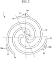
Fig. 2 is a plan view illustrating a driving-side scroll member inFig. 1 . -
Fig. 3 is a plan view illustrating a driven-side scroll member inFig. 1 . -
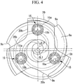
Fig. 4 is a side view of a driving-side supporting member inFig. 1 seen from the exhaust side. -
Fig. 5 is a side view of the driven-side supporting member inFig. 1 seen from the motor side. -
Fig. 6 is a longitudinal cross-sectional view illustrating a co-rotating scroll compressor according to a second embodiment of the present invention. - Embodiments according to the present invention are described below with reference to the drawings.
- A first embodiment of the present invention is described below with reference to
Fig. 1 and the like. -
Fig. 1 illustrates a co-rotating scroll compressor 1A. The co-rotating scroll compressor 1A can be used as a supercharger that compresses combustion air (fluid) to be supplied to an internal combustion engine such as a vehicle engine, for example. - The co-rotating scroll compressor 1A includes a
housing 3, and a driving-side scroll member 7 and the driven-side scroll member 9 accommodated in the other end side of thehousing 3. - The
housing 3 has a substantially cylindrical shape, and has one end (not shown) on which a motor accommodation portion that accommodates a drive unit such as an electric motor is provided. As illustrated inFig. 1 , ascroll accommodation portion 3b that accommodates the scroll members 7 and 9 are included on the other end. An exhaust opening 3d for exhausting air that has been compressed is formed in an end portion of thescroll accommodation portion 3b. Note that, although not shown inFig. 1 , an air suction opening that sucks air is provided in thehousing 3. - The rotational driving force from a rotor of the motor is transmitted to a driving-
side shaft portion 7c of the driving-side scroll member 7 that rotates about a driving rotational axis CL1. - The driving-side scroll member 7 includes a driving-
side end plate 7a, and a spiral driving-side wall 7b provided on one side of the driving-side end plate 7a. The driving-side end plate 7a is connected to the driving-side shaft portion 7c connected to a driving shaft 6, and extends in a direction orthogonal to the driving-side rotational axis CL1. The driving-side shaft portion 7c is provided so as to be rotatable with respect to thehousing 3 via a driving-side bearing 11 that is a ball bearing. - The driving-
side end plate 7a has a substantially disk-like shape when seen in planar view. As illustrated inFig. 2 , the driving-side scroll member 7 includes three spiral driving-side walls 7b, that is, three lines of spiral driving-side walls 7b. The three lines of driving-side walls 7b are provided about the driving-side rotational axis CL1 at regular intervals. Radiallyoutside end portions 7e of the driving-side walls 7b are not fixed to the other wall portions and are independent. That is, wall portions that connect the radially outsideend portions 7e to each other so as to provide reinforcement are not provided. - Driving-
side fixing portions 7f for fixing a driving-side supporting member 20 described below is provided near the radially outsideend portions 7e of the driving-side walls 7b. The driving-side fixing portion 7f is a bulging portion obtained by increasing the board thickness of the driving-side wall 7b radially outward. The forming position of the driving-side fixing portion 7f is a position separated from the radially outsideend portion 7e in the inner circumferential direction (winding starting direction) of the driving-side wall 7b. Specifically, an angle θ formed by the line connecting the driving-side rotational axis CL1 and the radiallyoutside end portion 7e to each other and the line connecting the driving-side rotational axis CL1 and the middle of the driving-side fixing portion 7f (more specifically, the center of afastening member 24a) to each other is 10° or more and 50° or less. - As illustrated in
Fig. 1 , the driven-side scroll member 9 is arranged so as to engage with the driving-side scroll member 7, and includes a driven-side end plate 9a and a spiral driven-side wall 9b provided on one side of the driven-side end plate 9a. A driven-side shaft portion 9c that extends in the direction of a driven-side rotational axis CL2 is connected to the driven-side end plate 9a. The driven-side shaft portion 9c is provided so as to be rotatable with respect to thehousing 3 via a driven-side bearing 13 that is a double row ball bearing. - The driven-
side end plate 9a has a substantially disk-like shape when seen in planar view. As illustrated inFig. 3 , three spiral driven-side walls 9b, that is, three lines of spiral driven-side walls 9b are provided in the driven-side scroll member 9. The three lines of driven-side walls 9b are arranged about the driven-side rotational axis CL2 at regular intervals. Anexhaust port 9d that exhausts air that has been compressed is formed in substantially the middle of the driven-side end plate 9a. Theexhaust port 9d communicates with theexhaust opening 3d formed in thehousing 3. Radiallyoutside end portions 9e of the driven-side walls 9b are not fixed to the other wall portions and are independent. That is, wall portions that connect the radially outsideend portions 9e to each other so as to provide reinforcement are not provided. - Driven-
side fixing portions 9f for fixing a driven-side supporting member 22 described below is provided near the radially outsideend portions 9e of the driven-side walls 9b. The driven-side fixing portion 9f is a bulging portion obtained by increasing the board thickness of the driven-side wall 9b radially outward. The forming position of the driven-side fixing portion 9f is a position separated from the radially outsideend portion 9e in the inner circumferential direction (winding starting direction) of the driven-side wall 9b. Specifically, an angle θ formed by the line connecting the driven-side rotational axis CL2 and the radiallyoutside end portion 9e to each other and the line connecting the driven-side rotational axis CL2 and the middle of the driven-side fixing portion 9f (more specifically, the center of afastening member 24b) to each other is 10° or more and 50° or less. - As described above, as illustrated in
Fig. 1 , the driving-side scroll member 7 rotates about the driving-side rotational axis CL1 and the driven-side scroll member 9 rotates about the driven-side rotational axis CL2. The driving-side rotational axis CL1 and the driven-side rotational axis CL2 are offset from each other by a distance with which a compression chamber can be formed. - As illustrated in
Fig. 1 , the driving-side supporting member 20 is fixed to the driving-side fixing portion 7f on the distal end (free end) of the driving-side wall 7b of the driving-side scroll member 7 via thefastening member 24a such as a pin or a bolt. The driven-side scroll member 9 is sandwiched between the driving-side supporting member 20 and the driving-side scroll member 7. Therefore, the driven-side end plate 9a is arranged so as to be opposed to the driving-side supporting member 20. - The driving-
side supporting member 20 includes ashaft portion 20a on the center side. Theshaft portion 20a is rotatably attached with respect to thehousing 3 via abearing 26 for the driving-side supporting member that is a ball bearing. As a result, the driving-side supporting member 20 rotates about the driving-side rotational axis CL1 as with the driving-side scroll member 7. - As illustrated in
Fig. 4 , the driving-side supporting member 20 includes aradially extending portion 20b that extends radially outward to the position of the outer periphery of the driving-side wall 7b for each position in which the distal end of the driving-side wall 7b is fixed by the fixingportion 7f (seeFig. 2 ). The region between the radially extendingportions 20b has a shape that does not extend to the outer periphery side of the driving-side wall 7b, and saves weight. In this embodiment, theradially extending portions 20b are provided in three directions at equiangular intervals. Note that, inFig. 4 , the driving-side supporting member 20 and the driven-side scroll member 9 are illustrated and the driving-side scroll member 7 is not illustrated. - As illustrated in
Fig. 1 , apin ring mechanism 15 is provided between the driving-side supporting member 20 and the driven-side end plate 9a. Thepin ring mechanism 15 is used as a synchronous driving mechanism that transmits driving force from the driving-side scroll member 7 to the driven-side scroll member 9 so that both of the scroll members 7 and 9 rotationally move in the same direction at the same angular velocity. That is, aring member 15a that is a ball bearing is provided in the driven-side end plate 9a, and apin member 15b is provided in the driving-side supporting member 20. As illustrated inFig. 4 , threepin members 15b are provided so as to correspond to the positions of theradially extending portions 20b of the driving-side supporting member 20. - As illustrated in
Fig. 1 , the driven-side supporting member 22 is fixed to the distal end (free end) of the driven-side wall 9b of the driven-side scroll member 9 via thefastening member 24b such as a pin or a bolt. The driving-side scroll member 7 is sandwiched between the driven-side supporting member 22 and the driven-side scroll member 9. Therefore, the driving-side end plate 7a is arranged so as to be opposed to the driven-side supporting member 22. - The driven-
side supporting member 22 includes ashaft portion 22a on the center side. Theshaft portion 22a is rotatably attached with respect to thehousing 3 via abearing 28 for the driven-side supporting member that is a ball bearing. As a result, the driven-side supporting member 22 rotates about the driven-side rotational axis CL2 as with the driven-side scroll member 9. - As illustrated in
Fig. 5 , the driven-side supporting member 22 includes aradially extending portion 22b that extends radially outward to the position of the outer periphery of the driven-side wall 9b for each position in which the distal end of the driven-side wall 9b is fixed. The region between the radially extendingportions 22b has a shape that does not extend to the outer periphery side of the driven-side wall 9b, and saves weight. In this embodiment, theradially extending portions 22b are provided in three directions at equiangular intervals. Note that, inFig. 5 , the driven-side supporting member 22 and the driving-side scroll member 7 are illustrated and the driven-side scroll member 9 is not illustrated. - As illustrated in
Fig. 1 , thepin ring mechanism 15 is provided between the driven-side supporting member 22 and the driving-side end plate 7a. Thepin ring mechanism 15 is used as a synchronous driving mechanism that transmits driving force from the driving-side scroll member 7 to the driven-side scroll member 9 so that both of the scroll members 7 and 9 rotationally move in the same direction at the same angular velocity. That is, thering member 15a is provided in the driving-side end plate 7a, and thepin member 15b is provided in the driven-side supporting member 22. As illustrated inFig. 5 , threepin members 15b are provided so as to correspond to the positions of theradially extending portions 22b of the driven-side supporting member 22. - The co-rotating scroll compressor 1A having the abovementioned configuration operates as follows. When the driving shaft is rotated about the driving-side rotational axis CL1 by the motor, the driving-
side shaft portion 7c connected to the driving shaft also rotates. As a result, the driving-side scroll member 7 rotates about the driving-side rotational axis CL1. When the driving-side scroll member 7 rotates, the driving force is transmitted from the driving-side end plate 7a to the driven-side supporting member 22 via thepin ring mechanism 15. Further, the driving force is transmitted from the driving-side supporting member 20 to the driven-side end plate 9a via thepin ring mechanism 15. As a result, the driving force is transmitted to the driven-side scroll member 9, and the driven-side scroll member 9 rotates about the driven-side rotational axis CL2. At this time, thepin member 15b of thepin ring mechanism 15 moves while being in contact with thering member 15a, and hence both of the scroll members 7 and 9 rotationally move in the same direction at the same angular velocity. - When both of the scroll members 7 and 9 rotationally move in the same direction at the same angular velocity, the air sucked from the suction opening in the
housing 3 is sucked from the outer periphery side of both of the scroll members 7 and 9, and is taken into the compression chamber formed by both of the scroll members 7 and 9. The capacity of the compression chamber decreases as the compression chamber approaches the center side, and air is compressed accordingly. The air compressed as above flows through theexhaust port 9d in the driven-side scroll member 9 and is exhausted to the outside from theexhaust opening 3d in thehousing 3. The exhausted compressed air is guided to an internal combustion engine (not shown) and is used as combustion air. - The effects of this embodiment is as follows.
- When the driving-side scroll member 7 and the driven-side scroll member 9 rotate and the number of revolutions increases, the distal ends of the
walls end plates walls end portions walls walls outside end portions members walls walls - The fixing
portions walls members walls portions end portions walls portions end portions portions portions end portions walls end portions walls portions end portions portions - The arrangement and the structure of the fixing
portions -
Fig. 6 illustrates aco-rotating scroll compressor 1B according to this embodiment. Note that structures similar to those in the co-rotating scroll compressor 1A described with reference toFig. 1 are the same denoted by the same reference character, and the description thereof is omitted. - As illustrated in
Fig. 6 , the driving-side scroll member 70 includes a first driving-side scroll portion 71 on the motor side (the right side inFig. 6 ) and a second driving-side scroll portion 72 on theexhaust opening 3d side. - The first driving-
side scroll portion 71 includes a first driving-side end plate 71a and a first driving-side wall 71b. Three lines of first driving-side walls 71b are provided as with the abovementioned driving-side walls 7b (seeFig. 2 ). - The second driving-
side scroll portion 72 includes a second driving-side end plate 72a and a second driving-side wall 72b. Three lines of second driving-side walls 72b are provided as with the abovementioned driving-side walls 7b (seeFig. 2 ). A second driving-side shaft portion 72c that extends in the direction of the driving-side rotational axis CL1 is connected to the second driving-side end plate 72a. The second driving-side shaft portion 72c is provided so as to be rotatable with respect to thehousing 3 via a second driving-side bearing 14 that is a ball bearing. Anexhaust port 72d is formed in the second driving-side shaft portion 72c along the driving-side rotational axis CL1. - The first driving-
side scroll portion 71 and the second driving-side scroll portion 72 are fixed in a state in which the distal ends (free ends) of thewalls side scroll portion 71 and the second driving-side scroll portion 72 are fixed by a bolt (wall fixing portion) 31 fastened with respect toflange parts 73 provided in a plurality of places so as to protrude radially outward. - The driven-
side scroll member 90 includes a driven-side end plate 90a provided in substantially the middle in the axial direction (the horizontal direction inFig. 6 ). A through hole (not shown) is formed in the middle of the driven-side end plate 90a, and air that has been compressed flows to theexhaust port 72d. - Driven-
side walls side end plate 90a. The first driven-side wall 91b provided from the driven-side end plate 90a to the motor side is engaged with the first driving-side wall 71b of the first driving-side scroll portion 71, and the second driven-side wall 92b provided from the driven-side end plate 90a to theexhaust opening 3d side is engaged with the second driving-side wall 72b of the second driving-side scroll portion 72. - A first supporting
member 33 and a second supportingmember 35 are provided on both ends of the driven-side scroll member 90 in the axial direction (the horizontal direction inFig. 6 ). The first supportingmember 33 is arranged on the motor side (the right side inFig. 6 ), and the second supportingmember 35 is arranged on theexhaust opening 3d side. The first supportingmember 33 is fixed to afirst fixing portion 91f on the distal end (free end) of the first driven-side wall 91b by afastening member 25a such as a pin or a bolt, and the second supportingmember 35 is fixed to asecond fixing portion 92f on the distal end (free end) of the second driven-side wall 92b by afastening member 25b such as a pin or a bolt. As with the driven-side fixing portion 9f described with reference toFig. 3 , the fixingportions side walls side walls side walls - A
shaft portion 33a is provided on the central axis side of the first supportingmember 33, and theshaft portion 33a is fixed to thehousing 3 via abearing 37 for the first supporting member. Ashaft portion 35a is provided on the central axis side of the second supportingmember 35, and theshaft portion 35a is fixed to thehousing 3 via abearing 38 for the second supporting member. As a result, the driven-side scroll member 90 is rotated about the second center axis CL2 via the supportingmembers members side supporting member 22 in the first embodiment described with reference toFig. 5 . - The
pin ring mechanism 15 is provided between the first supportingmember 33 and the first driving-side end plate 71a. That is, thering member 15a is provided in the first driving-side end plate 71a, and thepin member 15b is provided in the first supportingmember 33. As illustrated inFig. 5 , threepin members 15b are provided so as to correspond to the positions of the supporting portions of the first supportingmember 33. - The
pin ring mechanism 15 is provided between the second supportingmember 35 and the second driving-side end plate 72a. That is, thering member 15a is provided in the second driving-side end plate 72a, and thepin member 15b is provided in the second supportingmember 35. As illustrated inFig. 5 , threepin members 15b are provided so as to correspond to the positions of the supporting portions of the second supportingmember 35. - The
scroll accommodation portion 3b of thehousing 3 is divided at the substantially middle portion of thescroll members bolt 32. - The
co-rotating scroll compressor 1B having the abovementioned configuration operates as follows. - When the driving shaft connected to a rotor is rotated about the driving-side rotational axis CL1 by a motor, the driving-
side shaft portion 7c connected to the driving shaft also rotates. As a result, the driving-side scroll member 70 rotates about the driving-side rotational axis CL1. When the driving-side scroll member 70 rotates, the driving force is transmitted from the supportingmembers side scroll member 90 via thepin ring mechanism 15, and the driven-side scroll member 90 rotates about the driven-side rotational axis CL2. At this time, thepin member 15b of thepin ring mechanism 15 moves while being in contact with thering member 15a, and hence both of thescroll members - When both of the
scroll members housing 3 is sucked from the outer periphery side of both of thescroll members scroll members side wall 71b and the first driven-side wall 91b and the compression chamber formed by the second driving-side wall 72b and the second driven-side wall 92b are separately compressed. The capacity of the compression chambers decreases as the compression chambers approach the center side, and the air is compressed accordingly. The air compressed by the first driving-side wall 71b and the first driven-side wall 91b flows through a throughhole 90h formed in the driven-side end plate 90a, and is merged with air compressed by the second driving-side wall 72b and the second driven-side wall 92b. The merged air flows through theexhaust port 72d and is exhausted to the outside from theexhaust opening 3d in thehousing 3. The exhausted compressed air is guided to an internal combustion engine (not shown) and is used as combustion air. - Also in the
co-rotating scroll compressor 1B of this embodiment, as with the first embodiment, the fixingportions side walls portions - Note that, in the abovementioned embodiments, the co-rotating scroll compressor is used as the supercharger, but the present invention is not limited thereto, and the co-rotating scroll compressor can be widely used as long as fluid is compressed. For example, the co-rotating scroll compressor can be used as a refrigerant compressor used in an air conditioning unit.
- Further, as a "predetermined angular interval" by which the three lines of walls are separated about the center of the end plate, an equiangular interval that is 120° is preferred, but the present invention is not limited thereto. The angle tolerance for the equiangular interval is ±10°, and the interval may preferably be a substantially equiangular interval of which angle tolerance is ±1°.
- Further, the
pin ring mechanism 15 is used as a synchronous driving mechanism, but the present invention is not limited thereto, and thepin ring mechanism 15 may be used as a crank pin mechanism, for example. -
- 1A, 1B
- co-rotating scroll compressor
- 3
- housing
- 3b
- scroll accommodation portion
- 3d
- exhaust opening
- 7
- driving-side scroll member
- 7a
- driving-side end plate
- 7b
- driving-side wall
- 7c
- driving-side shaft portion
- 7e
- radially outside end portion
- 7f
- driving-side fixing portion
- 9
- driven-side scroll member
- 9a
- driven-side end plate
- 9b
- driven-side wall
- 9c
- driven-side shaft portion
- 9d
- exhaust port
- 9e
- radially outside end portion
- 9f
- driven-side fixing portion
- 11
- driving-side bearing
- 13
- driven-side bearing
- 15
- pin ring mechanism (synchronous driving mechanism)
- 15a
- ring member
- 15b
- pin member
- 20
- driving-side supporting member
- 20a
- shaft portion
- 20b
- radially extending portion
- 22
- driven-side supporting member
- 24a
- fastening member
- 24b
- fastening member
- 25a
- fastening member
- 25b
- fastening member
- 26
- bearing for driving-side supporting member
- 28
- bearing for driven-side supporting member
- 31
- bolt (wall fixing portion)
- 32
- bolt
- 33
- first supporting member
- 33a
- shaft portion
- 35
- second supporting member
- 35a
- shaft portion
- 37
- bearing for first supporting member
- 38
- bearing for second supporting member
- 70
- driving-side scroll member
- 71
- first driving-side scroll portion
- 71a
- first driving-side end plate
- 71b
- first driving-side wall
- 72
- second driving-side scroll portion
- 72a
- second driving-side end plate
- 72b
- second driving-side wall
- 72c
- second driving-side shaft portion
- 72d
- exhaust port
- 73
- flange part
- 90
- driven-side scroll member
- 90a
- driven-side end plate
- 90h
- through hole
- 91b
- first driven-side wall
- 91f
- first fixing portion
- 92b
- second driven-side wall
- 92f
- second fixing portion
Claims (3)
- A co-rotating scroll compressor, comprising:a driving-side scroll member driven by a drive unit so as to rotate, and comprising a plurality of spiral driving-side walls provided about a center of a driving-side end plate at predetermined angular intervals;a driven-side scroll member comprising spiral driven-side walls, the driven-side walls being provided about a center of a driven-side end plate at predetermined angular intervals and in a number corresponding to the driving-side walls, the driven-side walls being engaged with the corresponding driving-side walls so as to form a compression space;a synchronous driving mechanism that transmits driving force from the driving-side scroll member to the driven-side scroll member so that the driving-side scroll member and the driven-side scroll member rotationally move in a same direction at a same angular velocity; anda driving-side supporting member arranged across the driven-side end plate, fixed to free end sides of the driving-side walls in an arrangement direction, and rotated together with the driving-side scroll member, and/or a driven-side supporting member arranged across the driving-side end plate, fixed to a distal end side of the driven-side walls, and rotated together with the driven-side scroll member,wherein a fixing portion of each of the driving-side walls to which the driving-side supporting member is fixed is provided in a position close to a radially outside end portion of the driving-side wall and separated from the radially outside end portion in an inner circumferential direction of the driving-side wall, and/or a fixing portion of each of the driven-side walls to which the driven-side supporting member is fixed is provided in a position close to a radially outside end portion of the driven-side wall and separated from the radially outside end portion in an inner circumferential direction of the driven-side wall.
- The co-rotating scroll compressor according to claim 1, wherein:an angle formed by a line connecting a center of the driving-side wall and the radially outside end portion to each other and a line connecting the center of the driving-side wall and a middle of the fixing portion to each other is 10° or more and 40° or less when the driving-side wall is seen in planar view; and/oran angle formed by a line connecting a center of the driven-side wall and the radially outside end portion to each other and a line connecting the center of the driven-side wall and a middle of the fixing portion to each other is 10° or more and 40° or less when the driven-side wall is seen in planar view.
- The co-rotating scroll compressor according to claim 1 or 2, wherein:the driving-side scroll member comprises:a first driving-side scroll portion comprising a first driving-side end plate and a first driving-side wall, the first driving-side scroll portion being driven by the drive unit;a second driving-side scroll member comprising a second driving-side end plate and a second driving-side wall; anda wall fixing portion that performs fixing in a state in which distal ends of the first driving-side wall and the second driving-side wall in a rotation axis direction face each other;the driven-side scroll member comprises:a first driven-side wall provided on one side surface of the driven-side end plate, the first driven-side wall being engaged with the first driving-side wall; anda second driven-side wall provided on another side surface of the driven-side end plate, the second driven-side wall being engaged with the second driving-side wall; andthe driven-side supporting member comprises:a first supporting member arranged across the first driving-side end plate, fixed on a distal end side of the first driven-side wall in a rotation axis direction, and rotated together with the first driven-side wall; anda second supporting member arranged across the second driving-side end plate, fixed to a distal end side of the second driven-side wall in a rotation axis direction, and rotated together with the second driven-side wall.
Applications Claiming Priority (2)
| Application Number | Priority Date | Filing Date | Title |
|---|---|---|---|
| JP2016151542A JP6727978B2 (en) | 2016-08-01 | 2016-08-01 | Double rotary scroll compressor |
| PCT/JP2017/027944 WO2018025879A1 (en) | 2016-08-01 | 2017-08-01 | Double rotating scroll-type compressor |
Publications (3)
| Publication Number | Publication Date |
|---|---|
| EP3480466A1 true EP3480466A1 (en) | 2019-05-08 |
| EP3480466A4 EP3480466A4 (en) | 2019-06-26 |
| EP3480466B1 EP3480466B1 (en) | 2020-09-30 |
Family
ID=61072731
Family Applications (1)
| Application Number | Title | Priority Date | Filing Date |
|---|---|---|---|
| EP17836982.3A Not-in-force EP3480466B1 (en) | 2016-08-01 | 2017-08-01 | Double rotating scroll-type compressor |
Country Status (5)
| Country | Link |
|---|---|
| US (1) | US20190178249A1 (en) |
| EP (1) | EP3480466B1 (en) |
| JP (1) | JP6727978B2 (en) |
| CN (1) | CN109661518B (en) |
| WO (1) | WO2018025879A1 (en) |
Cited By (1)
| Publication number | Priority date | Publication date | Assignee | Title |
|---|---|---|---|---|
| EP3540230A1 (en) * | 2018-03-12 | 2019-09-18 | Mitsubishi Heavy Industries, Ltd. | Co-rotating scroll compressor |
Families Citing this family (4)
| Publication number | Priority date | Publication date | Assignee | Title |
|---|---|---|---|---|
| WO2019171448A1 (en) * | 2018-03-06 | 2019-09-12 | 三菱重工業株式会社 | Double-rotating scroll compressor |
| CN114729637B (en) * | 2019-11-15 | 2024-07-02 | 谷轮有限合伙公司 | Co-rotating scroll compressor |
| US12104594B2 (en) | 2021-11-05 | 2024-10-01 | Copeland Lp | Co-rotating compressor |
| US11624366B1 (en) | 2021-11-05 | 2023-04-11 | Emerson Climate Technologies, Inc. | Co-rotating scroll compressor having first and second Oldham couplings |
Family Cites Families (8)
| Publication number | Priority date | Publication date | Assignee | Title |
|---|---|---|---|---|
| JPS5360443A (en) | 1976-11-10 | 1978-05-31 | Hitachi Ltd | Shaft bearing device |
| US6884047B1 (en) * | 2003-10-20 | 2005-04-26 | Varian, Inc. | Compact scroll pump |
| JP5812693B2 (en) * | 2011-05-09 | 2015-11-17 | アネスト岩田株式会社 | Scroll type fluid machine |
| US20130236344A1 (en) * | 2012-03-09 | 2013-09-12 | RichStone Limited (Korea) | Scroll fluid machine |
| JP5925578B2 (en) * | 2012-04-25 | 2016-05-25 | アネスト岩田株式会社 | Scroll expander |
| JP5931564B2 (en) * | 2012-04-25 | 2016-06-08 | アネスト岩田株式会社 | Double-rotating scroll expander and power generation device including the expander |
| JP6185297B2 (en) * | 2013-06-14 | 2017-08-23 | アネスト岩田株式会社 | Scroll type fluid machine |
| JP6441645B2 (en) * | 2014-11-07 | 2018-12-19 | アネスト岩田株式会社 | Scroll fluid machinery |
-
2016
- 2016-08-01 JP JP2016151542A patent/JP6727978B2/en active Active
-
2017
- 2017-08-01 CN CN201780047230.5A patent/CN109661518B/en not_active Expired - Fee Related
- 2017-08-01 US US16/321,920 patent/US20190178249A1/en not_active Abandoned
- 2017-08-01 WO PCT/JP2017/027944 patent/WO2018025879A1/en not_active Ceased
- 2017-08-01 EP EP17836982.3A patent/EP3480466B1/en not_active Not-in-force
Cited By (1)
| Publication number | Priority date | Publication date | Assignee | Title |
|---|---|---|---|---|
| EP3540230A1 (en) * | 2018-03-12 | 2019-09-18 | Mitsubishi Heavy Industries, Ltd. | Co-rotating scroll compressor |
Also Published As
| Publication number | Publication date |
|---|---|
| WO2018025879A1 (en) | 2018-02-08 |
| EP3480466A4 (en) | 2019-06-26 |
| CN109661518A (en) | 2019-04-19 |
| CN109661518B (en) | 2021-01-01 |
| JP6727978B2 (en) | 2020-07-22 |
| JP2018021463A (en) | 2018-02-08 |
| EP3480466B1 (en) | 2020-09-30 |
| US20190178249A1 (en) | 2019-06-13 |
Similar Documents
| Publication | Publication Date | Title |
|---|---|---|
| EP3480466B1 (en) | Double rotating scroll-type compressor | |
| US11015599B2 (en) | Co-rotating scroll compressor and method for designing the same | |
| US11041494B2 (en) | Co-rotating scroll compressor | |
| US20190376513A1 (en) | Co-rotating scroll compressor and method of assembling the same | |
| EP3489514B1 (en) | Bidirectional-rotation-type scroll compressor | |
| JP6108967B2 (en) | Rotary compression mechanism | |
| US8157553B2 (en) | Scroll compressor having a shifted gravity center | |
| EP3480464B1 (en) | Double rotating scroll-type compressor | |
| EP3567252B1 (en) | Two-way-rotating scroll compressor | |
| EP3540230B1 (en) | Co-rotating scroll compressor | |
| JP2018059462A (en) | Double rotation scroll-type compressor | |
| JP2020186660A (en) | Rotary compressor | |
| WO2019171448A1 (en) | Double-rotating scroll compressor | |
| EP3530945A1 (en) | Double rotating scroll type compressor | |
| JP2018132034A (en) | Bidirectional rotation scroll type compressor |
Legal Events
| Date | Code | Title | Description |
|---|---|---|---|
| STAA | Information on the status of an ep patent application or granted ep patent |
Free format text: STATUS: THE INTERNATIONAL PUBLICATION HAS BEEN MADE |
|
| PUAI | Public reference made under article 153(3) epc to a published international application that has entered the european phase |
Free format text: ORIGINAL CODE: 0009012 |
|
| STAA | Information on the status of an ep patent application or granted ep patent |
Free format text: STATUS: REQUEST FOR EXAMINATION WAS MADE |
|
| 17P | Request for examination filed |
Effective date: 20190131 |
|
| AK | Designated contracting states |
Kind code of ref document: A1 Designated state(s): AL AT BE BG CH CY CZ DE DK EE ES FI FR GB GR HR HU IE IS IT LI LT LU LV MC MK MT NL NO PL PT RO RS SE SI SK SM TR |
|
| AX | Request for extension of the european patent |
Extension state: BA ME |
|
| A4 | Supplementary search report drawn up and despatched |
Effective date: 20190524 |
|
| RIC1 | Information provided on ipc code assigned before grant |
Ipc: F01C 17/06 20060101ALI20190520BHEP Ipc: F04C 18/02 20060101AFI20190520BHEP |
|
| DAV | Request for validation of the european patent (deleted) | ||
| DAX | Request for extension of the european patent (deleted) | ||
| RAP1 | Party data changed (applicant data changed or rights of an application transferred) |
Owner name: MITSUBISHI HEAVY INDUSTRIES, LTD. |
|
| STAA | Information on the status of an ep patent application or granted ep patent |
Free format text: STATUS: EXAMINATION IS IN PROGRESS |
|
| 17Q | First examination report despatched |
Effective date: 20200131 |
|
| GRAP | Despatch of communication of intention to grant a patent |
Free format text: ORIGINAL CODE: EPIDOSNIGR1 |
|
| STAA | Information on the status of an ep patent application or granted ep patent |
Free format text: STATUS: GRANT OF PATENT IS INTENDED |
|
| INTG | Intention to grant announced |
Effective date: 20200429 |
|
| GRAS | Grant fee paid |
Free format text: ORIGINAL CODE: EPIDOSNIGR3 |
|
| GRAA | (expected) grant |
Free format text: ORIGINAL CODE: 0009210 |
|
| STAA | Information on the status of an ep patent application or granted ep patent |
Free format text: STATUS: THE PATENT HAS BEEN GRANTED |
|
| AK | Designated contracting states |
Kind code of ref document: B1 Designated state(s): AL AT BE BG CH CY CZ DE DK EE ES FI FR GB GR HR HU IE IS IT LI LT LU LV MC MK MT NL NO PL PT RO RS SE SI SK SM TR |
|
| REG | Reference to a national code |
Ref country code: CH Ref legal event code: EP Ref country code: GB Ref legal event code: FG4D |
|
| REG | Reference to a national code |
Ref country code: AT Ref legal event code: REF Ref document number: 1319065 Country of ref document: AT Kind code of ref document: T Effective date: 20201015 |
|
| REG | Reference to a national code |
Ref country code: DE Ref legal event code: R096 Ref document number: 602017024778 Country of ref document: DE |
|
| REG | Reference to a national code |
Ref country code: IE Ref legal event code: FG4D |
|
| PG25 | Lapsed in a contracting state [announced via postgrant information from national office to epo] |
Ref country code: BG Free format text: LAPSE BECAUSE OF FAILURE TO SUBMIT A TRANSLATION OF THE DESCRIPTION OR TO PAY THE FEE WITHIN THE PRESCRIBED TIME-LIMIT Effective date: 20201230 Ref country code: SE Free format text: LAPSE BECAUSE OF FAILURE TO SUBMIT A TRANSLATION OF THE DESCRIPTION OR TO PAY THE FEE WITHIN THE PRESCRIBED TIME-LIMIT Effective date: 20200930 Ref country code: FI Free format text: LAPSE BECAUSE OF FAILURE TO SUBMIT A TRANSLATION OF THE DESCRIPTION OR TO PAY THE FEE WITHIN THE PRESCRIBED TIME-LIMIT Effective date: 20200930 Ref country code: GR Free format text: LAPSE BECAUSE OF FAILURE TO SUBMIT A TRANSLATION OF THE DESCRIPTION OR TO PAY THE FEE WITHIN THE PRESCRIBED TIME-LIMIT Effective date: 20201231 Ref country code: NO Free format text: LAPSE BECAUSE OF FAILURE TO SUBMIT A TRANSLATION OF THE DESCRIPTION OR TO PAY THE FEE WITHIN THE PRESCRIBED TIME-LIMIT Effective date: 20201230 Ref country code: HR Free format text: LAPSE BECAUSE OF FAILURE TO SUBMIT A TRANSLATION OF THE DESCRIPTION OR TO PAY THE FEE WITHIN THE PRESCRIBED TIME-LIMIT Effective date: 20200930 |
|
| REG | Reference to a national code |
Ref country code: AT Ref legal event code: MK05 Ref document number: 1319065 Country of ref document: AT Kind code of ref document: T Effective date: 20200930 |
|
| PG25 | Lapsed in a contracting state [announced via postgrant information from national office to epo] |
Ref country code: LV Free format text: LAPSE BECAUSE OF FAILURE TO SUBMIT A TRANSLATION OF THE DESCRIPTION OR TO PAY THE FEE WITHIN THE PRESCRIBED TIME-LIMIT Effective date: 20200930 Ref country code: RS Free format text: LAPSE BECAUSE OF FAILURE TO SUBMIT A TRANSLATION OF THE DESCRIPTION OR TO PAY THE FEE WITHIN THE PRESCRIBED TIME-LIMIT Effective date: 20200930 |
|
| REG | Reference to a national code |
Ref country code: NL Ref legal event code: MP Effective date: 20200930 |
|
| REG | Reference to a national code |
Ref country code: LT Ref legal event code: MG4D |
|
| PG25 | Lapsed in a contracting state [announced via postgrant information from national office to epo] |
Ref country code: CZ Free format text: LAPSE BECAUSE OF FAILURE TO SUBMIT A TRANSLATION OF THE DESCRIPTION OR TO PAY THE FEE WITHIN THE PRESCRIBED TIME-LIMIT Effective date: 20200930 Ref country code: RO Free format text: LAPSE BECAUSE OF FAILURE TO SUBMIT A TRANSLATION OF THE DESCRIPTION OR TO PAY THE FEE WITHIN THE PRESCRIBED TIME-LIMIT Effective date: 20200930 Ref country code: PT Free format text: LAPSE BECAUSE OF FAILURE TO SUBMIT A TRANSLATION OF THE DESCRIPTION OR TO PAY THE FEE WITHIN THE PRESCRIBED TIME-LIMIT Effective date: 20210201 Ref country code: EE Free format text: LAPSE BECAUSE OF FAILURE TO SUBMIT A TRANSLATION OF THE DESCRIPTION OR TO PAY THE FEE WITHIN THE PRESCRIBED TIME-LIMIT Effective date: 20200930 Ref country code: LT Free format text: LAPSE BECAUSE OF FAILURE TO SUBMIT A TRANSLATION OF THE DESCRIPTION OR TO PAY THE FEE WITHIN THE PRESCRIBED TIME-LIMIT Effective date: 20200930 Ref country code: SM Free format text: LAPSE BECAUSE OF FAILURE TO SUBMIT A TRANSLATION OF THE DESCRIPTION OR TO PAY THE FEE WITHIN THE PRESCRIBED TIME-LIMIT Effective date: 20200930 |
|
| PG25 | Lapsed in a contracting state [announced via postgrant information from national office to epo] |
Ref country code: AT Free format text: LAPSE BECAUSE OF FAILURE TO SUBMIT A TRANSLATION OF THE DESCRIPTION OR TO PAY THE FEE WITHIN THE PRESCRIBED TIME-LIMIT Effective date: 20200930 Ref country code: AL Free format text: LAPSE BECAUSE OF FAILURE TO SUBMIT A TRANSLATION OF THE DESCRIPTION OR TO PAY THE FEE WITHIN THE PRESCRIBED TIME-LIMIT Effective date: 20200930 Ref country code: ES Free format text: LAPSE BECAUSE OF FAILURE TO SUBMIT A TRANSLATION OF THE DESCRIPTION OR TO PAY THE FEE WITHIN THE PRESCRIBED TIME-LIMIT Effective date: 20200930 Ref country code: IS Free format text: LAPSE BECAUSE OF FAILURE TO SUBMIT A TRANSLATION OF THE DESCRIPTION OR TO PAY THE FEE WITHIN THE PRESCRIBED TIME-LIMIT Effective date: 20210130 Ref country code: PL Free format text: LAPSE BECAUSE OF FAILURE TO SUBMIT A TRANSLATION OF THE DESCRIPTION OR TO PAY THE FEE WITHIN THE PRESCRIBED TIME-LIMIT Effective date: 20200930 |
|
| PG25 | Lapsed in a contracting state [announced via postgrant information from national office to epo] |
Ref country code: NL Free format text: LAPSE BECAUSE OF FAILURE TO SUBMIT A TRANSLATION OF THE DESCRIPTION OR TO PAY THE FEE WITHIN THE PRESCRIBED TIME-LIMIT Effective date: 20200930 Ref country code: SK Free format text: LAPSE BECAUSE OF FAILURE TO SUBMIT A TRANSLATION OF THE DESCRIPTION OR TO PAY THE FEE WITHIN THE PRESCRIBED TIME-LIMIT Effective date: 20200930 |
|
| REG | Reference to a national code |
Ref country code: DE Ref legal event code: R097 Ref document number: 602017024778 Country of ref document: DE |
|
| PLBE | No opposition filed within time limit |
Free format text: ORIGINAL CODE: 0009261 |
|
| STAA | Information on the status of an ep patent application or granted ep patent |
Free format text: STATUS: NO OPPOSITION FILED WITHIN TIME LIMIT |
|
| PG25 | Lapsed in a contracting state [announced via postgrant information from national office to epo] |
Ref country code: DK Free format text: LAPSE BECAUSE OF FAILURE TO SUBMIT A TRANSLATION OF THE DESCRIPTION OR TO PAY THE FEE WITHIN THE PRESCRIBED TIME-LIMIT Effective date: 20200930 |
|
| 26N | No opposition filed |
Effective date: 20210701 |
|
| PG25 | Lapsed in a contracting state [announced via postgrant information from national office to epo] |
Ref country code: IT Free format text: LAPSE BECAUSE OF FAILURE TO SUBMIT A TRANSLATION OF THE DESCRIPTION OR TO PAY THE FEE WITHIN THE PRESCRIBED TIME-LIMIT Effective date: 20200930 |
|
| PG25 | Lapsed in a contracting state [announced via postgrant information from national office to epo] |
Ref country code: SI Free format text: LAPSE BECAUSE OF FAILURE TO SUBMIT A TRANSLATION OF THE DESCRIPTION OR TO PAY THE FEE WITHIN THE PRESCRIBED TIME-LIMIT Effective date: 20200930 |
|
| PGFP | Annual fee paid to national office [announced via postgrant information from national office to epo] |
Ref country code: DE Payment date: 20210630 Year of fee payment: 5 Ref country code: GB Payment date: 20210701 Year of fee payment: 5 |
|
| REG | Reference to a national code |
Ref country code: CH Ref legal event code: PL |
|
| PG25 | Lapsed in a contracting state [announced via postgrant information from national office to epo] |
Ref country code: MC Free format text: LAPSE BECAUSE OF FAILURE TO SUBMIT A TRANSLATION OF THE DESCRIPTION OR TO PAY THE FEE WITHIN THE PRESCRIBED TIME-LIMIT Effective date: 20200930 |
|
| REG | Reference to a national code |
Ref country code: BE Ref legal event code: MM Effective date: 20210831 |
|
| PG25 | Lapsed in a contracting state [announced via postgrant information from national office to epo] |
Ref country code: LI Free format text: LAPSE BECAUSE OF NON-PAYMENT OF DUE FEES Effective date: 20210831 Ref country code: CH Free format text: LAPSE BECAUSE OF NON-PAYMENT OF DUE FEES Effective date: 20210831 |
|
| PG25 | Lapsed in a contracting state [announced via postgrant information from national office to epo] |
Ref country code: IS Free format text: LAPSE BECAUSE OF FAILURE TO SUBMIT A TRANSLATION OF THE DESCRIPTION OR TO PAY THE FEE WITHIN THE PRESCRIBED TIME-LIMIT Effective date: 20210130 Ref country code: LU Free format text: LAPSE BECAUSE OF NON-PAYMENT OF DUE FEES Effective date: 20210801 |
|
| PG25 | Lapsed in a contracting state [announced via postgrant information from national office to epo] |
Ref country code: IE Free format text: LAPSE BECAUSE OF NON-PAYMENT OF DUE FEES Effective date: 20210801 Ref country code: FR Free format text: LAPSE BECAUSE OF NON-PAYMENT OF DUE FEES Effective date: 20210831 Ref country code: BE Free format text: LAPSE BECAUSE OF NON-PAYMENT OF DUE FEES Effective date: 20210831 |
|
| REG | Reference to a national code |
Ref country code: DE Ref legal event code: R119 Ref document number: 602017024778 Country of ref document: DE |
|
| REG | Reference to a national code |
Ref country code: DE Ref legal event code: R082 Ref document number: 602017024778 Country of ref document: DE Representative=s name: CBDL PATENTANWAELTE GBR, DE |
|
| GBPC | Gb: european patent ceased through non-payment of renewal fee |
Effective date: 20220801 |
|
| PG25 | Lapsed in a contracting state [announced via postgrant information from national office to epo] |
Ref country code: CY Free format text: LAPSE BECAUSE OF FAILURE TO SUBMIT A TRANSLATION OF THE DESCRIPTION OR TO PAY THE FEE WITHIN THE PRESCRIBED TIME-LIMIT Effective date: 20200930 |
|
| PG25 | Lapsed in a contracting state [announced via postgrant information from national office to epo] |
Ref country code: HU Free format text: LAPSE BECAUSE OF FAILURE TO SUBMIT A TRANSLATION OF THE DESCRIPTION OR TO PAY THE FEE WITHIN THE PRESCRIBED TIME-LIMIT; INVALID AB INITIO Effective date: 20170801 Ref country code: DE Free format text: LAPSE BECAUSE OF NON-PAYMENT OF DUE FEES Effective date: 20230301 |
|
| PG25 | Lapsed in a contracting state [announced via postgrant information from national office to epo] |
Ref country code: GB Free format text: LAPSE BECAUSE OF NON-PAYMENT OF DUE FEES Effective date: 20220801 |
|
| PG25 | Lapsed in a contracting state [announced via postgrant information from national office to epo] |
Ref country code: MK Free format text: LAPSE BECAUSE OF FAILURE TO SUBMIT A TRANSLATION OF THE DESCRIPTION OR TO PAY THE FEE WITHIN THE PRESCRIBED TIME-LIMIT Effective date: 20200930 |
|
| PG25 | Lapsed in a contracting state [announced via postgrant information from national office to epo] |
Ref country code: TR Free format text: LAPSE BECAUSE OF FAILURE TO SUBMIT A TRANSLATION OF THE DESCRIPTION OR TO PAY THE FEE WITHIN THE PRESCRIBED TIME-LIMIT Effective date: 20200930 |
|
| PG25 | Lapsed in a contracting state [announced via postgrant information from national office to epo] |
Ref country code: MT Free format text: LAPSE BECAUSE OF FAILURE TO SUBMIT A TRANSLATION OF THE DESCRIPTION OR TO PAY THE FEE WITHIN THE PRESCRIBED TIME-LIMIT Effective date: 20200930 |