EP3480459A1 - Gas supplying apparatus - Google Patents
Gas supplying apparatus Download PDFInfo
- Publication number
- EP3480459A1 EP3480459A1 EP18201260.9A EP18201260A EP3480459A1 EP 3480459 A1 EP3480459 A1 EP 3480459A1 EP 18201260 A EP18201260 A EP 18201260A EP 3480459 A1 EP3480459 A1 EP 3480459A1
- Authority
- EP
- European Patent Office
- Prior art keywords
- duct
- compressor
- additional
- port
- exhaust
- Prior art date
- Legal status (The legal status is an assumption and is not a legal conclusion. Google has not performed a legal analysis and makes no representation as to the accuracy of the status listed.)
- Granted
Links
Images



Classifications
-
- F—MECHANICAL ENGINEERING; LIGHTING; HEATING; WEAPONS; BLASTING
- F17—STORING OR DISTRIBUTING GASES OR LIQUIDS
- F17C—VESSELS FOR CONTAINING OR STORING COMPRESSED, LIQUEFIED OR SOLIDIFIED GASES; FIXED-CAPACITY GAS-HOLDERS; FILLING VESSELS WITH, OR DISCHARGING FROM VESSELS, COMPRESSED, LIQUEFIED, OR SOLIDIFIED GASES
- F17C5/00—Methods or apparatus for filling containers with liquefied, solidified, or compressed gases under pressures
- F17C5/06—Methods or apparatus for filling containers with liquefied, solidified, or compressed gases under pressures for filling with compressed gases
-
- F—MECHANICAL ENGINEERING; LIGHTING; HEATING; WEAPONS; BLASTING
- F04—POSITIVE - DISPLACEMENT MACHINES FOR LIQUIDS; PUMPS FOR LIQUIDS OR ELASTIC FLUIDS
- F04B—POSITIVE-DISPLACEMENT MACHINES FOR LIQUIDS; PUMPS
- F04B39/00—Component parts, details, or accessories, of pumps or pumping systems specially adapted for elastic fluids, not otherwise provided for in, or of interest apart from, groups F04B25/00 - F04B37/00
- F04B39/0027—Pulsation and noise damping means
- F04B39/0033—Pulsation and noise damping means with encapsulations
-
- F—MECHANICAL ENGINEERING; LIGHTING; HEATING; WEAPONS; BLASTING
- F04—POSITIVE - DISPLACEMENT MACHINES FOR LIQUIDS; PUMPS FOR LIQUIDS OR ELASTIC FLUIDS
- F04B—POSITIVE-DISPLACEMENT MACHINES FOR LIQUIDS; PUMPS
- F04B39/00—Component parts, details, or accessories, of pumps or pumping systems specially adapted for elastic fluids, not otherwise provided for in, or of interest apart from, groups F04B25/00 - F04B37/00
- F04B39/06—Cooling; Heating; Prevention of freezing
-
- F—MECHANICAL ENGINEERING; LIGHTING; HEATING; WEAPONS; BLASTING
- F04—POSITIVE - DISPLACEMENT MACHINES FOR LIQUIDS; PUMPS FOR LIQUIDS OR ELASTIC FLUIDS
- F04B—POSITIVE-DISPLACEMENT MACHINES FOR LIQUIDS; PUMPS
- F04B39/00—Component parts, details, or accessories, of pumps or pumping systems specially adapted for elastic fluids, not otherwise provided for in, or of interest apart from, groups F04B25/00 - F04B37/00
- F04B39/12—Casings; Cylinders; Cylinder heads; Fluid connections
- F04B39/121—Casings
-
- F—MECHANICAL ENGINEERING; LIGHTING; HEATING; WEAPONS; BLASTING
- F17—STORING OR DISTRIBUTING GASES OR LIQUIDS
- F17C—VESSELS FOR CONTAINING OR STORING COMPRESSED, LIQUEFIED OR SOLIDIFIED GASES; FIXED-CAPACITY GAS-HOLDERS; FILLING VESSELS WITH, OR DISCHARGING FROM VESSELS, COMPRESSED, LIQUEFIED, OR SOLIDIFIED GASES
- F17C13/00—Details of vessels or of the filling or discharging of vessels
- F17C13/12—Arrangements or mounting of devices for preventing or minimising the effect of explosion ; Other safety measures
-
- F—MECHANICAL ENGINEERING; LIGHTING; HEATING; WEAPONS; BLASTING
- F17—STORING OR DISTRIBUTING GASES OR LIQUIDS
- F17C—VESSELS FOR CONTAINING OR STORING COMPRESSED, LIQUEFIED OR SOLIDIFIED GASES; FIXED-CAPACITY GAS-HOLDERS; FILLING VESSELS WITH, OR DISCHARGING FROM VESSELS, COMPRESSED, LIQUEFIED, OR SOLIDIFIED GASES
- F17C5/00—Methods or apparatus for filling containers with liquefied, solidified, or compressed gases under pressures
- F17C5/002—Automated filling apparatus
- F17C5/007—Automated filling apparatus for individual gas tanks or containers, e.g. in vehicles
-
- F—MECHANICAL ENGINEERING; LIGHTING; HEATING; WEAPONS; BLASTING
- F04—POSITIVE - DISPLACEMENT MACHINES FOR LIQUIDS; PUMPS FOR LIQUIDS OR ELASTIC FLUIDS
- F04B—POSITIVE-DISPLACEMENT MACHINES FOR LIQUIDS; PUMPS
- F04B39/00—Component parts, details, or accessories, of pumps or pumping systems specially adapted for elastic fluids, not otherwise provided for in, or of interest apart from, groups F04B25/00 - F04B37/00
- F04B39/06—Cooling; Heating; Prevention of freezing
- F04B39/066—Cooling by ventilation
-
- F—MECHANICAL ENGINEERING; LIGHTING; HEATING; WEAPONS; BLASTING
- F04—POSITIVE - DISPLACEMENT MACHINES FOR LIQUIDS; PUMPS FOR LIQUIDS OR ELASTIC FLUIDS
- F04C—ROTARY-PISTON, OR OSCILLATING-PISTON, POSITIVE-DISPLACEMENT MACHINES FOR LIQUIDS; ROTARY-PISTON, OR OSCILLATING-PISTON, POSITIVE-DISPLACEMENT PUMPS
- F04C2210/00—Fluid
- F04C2210/10—Fluid working
- F04C2210/1055—Hydrogen (H2)
-
- F—MECHANICAL ENGINEERING; LIGHTING; HEATING; WEAPONS; BLASTING
- F17—STORING OR DISTRIBUTING GASES OR LIQUIDS
- F17C—VESSELS FOR CONTAINING OR STORING COMPRESSED, LIQUEFIED OR SOLIDIFIED GASES; FIXED-CAPACITY GAS-HOLDERS; FILLING VESSELS WITH, OR DISCHARGING FROM VESSELS, COMPRESSED, LIQUEFIED, OR SOLIDIFIED GASES
- F17C2205/00—Vessel construction, in particular mounting arrangements, attachments or identifications means
- F17C2205/01—Mounting arrangements
- F17C2205/0103—Exterior arrangements
-
- F—MECHANICAL ENGINEERING; LIGHTING; HEATING; WEAPONS; BLASTING
- F17—STORING OR DISTRIBUTING GASES OR LIQUIDS
- F17C—VESSELS FOR CONTAINING OR STORING COMPRESSED, LIQUEFIED OR SOLIDIFIED GASES; FIXED-CAPACITY GAS-HOLDERS; FILLING VESSELS WITH, OR DISCHARGING FROM VESSELS, COMPRESSED, LIQUEFIED, OR SOLIDIFIED GASES
- F17C2205/00—Vessel construction, in particular mounting arrangements, attachments or identifications means
- F17C2205/01—Mounting arrangements
- F17C2205/0123—Mounting arrangements characterised by number of vessels
- F17C2205/013—Two or more vessels
- F17C2205/0134—Two or more vessels characterised by the presence of fluid connection between vessels
- F17C2205/0142—Two or more vessels characterised by the presence of fluid connection between vessels bundled in parallel
-
- F—MECHANICAL ENGINEERING; LIGHTING; HEATING; WEAPONS; BLASTING
- F17—STORING OR DISTRIBUTING GASES OR LIQUIDS
- F17C—VESSELS FOR CONTAINING OR STORING COMPRESSED, LIQUEFIED OR SOLIDIFIED GASES; FIXED-CAPACITY GAS-HOLDERS; FILLING VESSELS WITH, OR DISCHARGING FROM VESSELS, COMPRESSED, LIQUEFIED, OR SOLIDIFIED GASES
- F17C2205/00—Vessel construction, in particular mounting arrangements, attachments or identifications means
- F17C2205/01—Mounting arrangements
- F17C2205/0153—Details of mounting arrangements
- F17C2205/0176—Details of mounting arrangements with ventilation
-
- F—MECHANICAL ENGINEERING; LIGHTING; HEATING; WEAPONS; BLASTING
- F17—STORING OR DISTRIBUTING GASES OR LIQUIDS
- F17C—VESSELS FOR CONTAINING OR STORING COMPRESSED, LIQUEFIED OR SOLIDIFIED GASES; FIXED-CAPACITY GAS-HOLDERS; FILLING VESSELS WITH, OR DISCHARGING FROM VESSELS, COMPRESSED, LIQUEFIED, OR SOLIDIFIED GASES
- F17C2205/00—Vessel construction, in particular mounting arrangements, attachments or identifications means
- F17C2205/03—Fluid connections, filters, valves, closure means or other attachments
- F17C2205/0302—Fittings, valves, filters, or components in connection with the gas storage device
- F17C2205/0323—Valves
- F17C2205/0326—Valves electrically actuated
-
- F—MECHANICAL ENGINEERING; LIGHTING; HEATING; WEAPONS; BLASTING
- F17—STORING OR DISTRIBUTING GASES OR LIQUIDS
- F17C—VESSELS FOR CONTAINING OR STORING COMPRESSED, LIQUEFIED OR SOLIDIFIED GASES; FIXED-CAPACITY GAS-HOLDERS; FILLING VESSELS WITH, OR DISCHARGING FROM VESSELS, COMPRESSED, LIQUEFIED, OR SOLIDIFIED GASES
- F17C2221/00—Handled fluid, in particular type of fluid
- F17C2221/01—Pure fluids
- F17C2221/012—Hydrogen
-
- F—MECHANICAL ENGINEERING; LIGHTING; HEATING; WEAPONS; BLASTING
- F17—STORING OR DISTRIBUTING GASES OR LIQUIDS
- F17C—VESSELS FOR CONTAINING OR STORING COMPRESSED, LIQUEFIED OR SOLIDIFIED GASES; FIXED-CAPACITY GAS-HOLDERS; FILLING VESSELS WITH, OR DISCHARGING FROM VESSELS, COMPRESSED, LIQUEFIED, OR SOLIDIFIED GASES
- F17C2223/00—Handled fluid before transfer, i.e. state of fluid when stored in the vessel or before transfer from the vessel
- F17C2223/01—Handled fluid before transfer, i.e. state of fluid when stored in the vessel or before transfer from the vessel characterised by the phase
- F17C2223/0107—Single phase
- F17C2223/0123—Single phase gaseous, e.g. CNG, GNC
-
- F—MECHANICAL ENGINEERING; LIGHTING; HEATING; WEAPONS; BLASTING
- F17—STORING OR DISTRIBUTING GASES OR LIQUIDS
- F17C—VESSELS FOR CONTAINING OR STORING COMPRESSED, LIQUEFIED OR SOLIDIFIED GASES; FIXED-CAPACITY GAS-HOLDERS; FILLING VESSELS WITH, OR DISCHARGING FROM VESSELS, COMPRESSED, LIQUEFIED, OR SOLIDIFIED GASES
- F17C2223/00—Handled fluid before transfer, i.e. state of fluid when stored in the vessel or before transfer from the vessel
- F17C2223/03—Handled fluid before transfer, i.e. state of fluid when stored in the vessel or before transfer from the vessel characterised by the pressure level
- F17C2223/033—Small pressure, e.g. for liquefied gas
-
- F—MECHANICAL ENGINEERING; LIGHTING; HEATING; WEAPONS; BLASTING
- F17—STORING OR DISTRIBUTING GASES OR LIQUIDS
- F17C—VESSELS FOR CONTAINING OR STORING COMPRESSED, LIQUEFIED OR SOLIDIFIED GASES; FIXED-CAPACITY GAS-HOLDERS; FILLING VESSELS WITH, OR DISCHARGING FROM VESSELS, COMPRESSED, LIQUEFIED, OR SOLIDIFIED GASES
- F17C2225/00—Handled fluid after transfer, i.e. state of fluid after transfer from the vessel
- F17C2225/01—Handled fluid after transfer, i.e. state of fluid after transfer from the vessel characterised by the phase
- F17C2225/0107—Single phase
- F17C2225/0123—Single phase gaseous, e.g. CNG, GNC
-
- F—MECHANICAL ENGINEERING; LIGHTING; HEATING; WEAPONS; BLASTING
- F17—STORING OR DISTRIBUTING GASES OR LIQUIDS
- F17C—VESSELS FOR CONTAINING OR STORING COMPRESSED, LIQUEFIED OR SOLIDIFIED GASES; FIXED-CAPACITY GAS-HOLDERS; FILLING VESSELS WITH, OR DISCHARGING FROM VESSELS, COMPRESSED, LIQUEFIED, OR SOLIDIFIED GASES
- F17C2225/00—Handled fluid after transfer, i.e. state of fluid after transfer from the vessel
- F17C2225/03—Handled fluid after transfer, i.e. state of fluid after transfer from the vessel characterised by the pressure level
- F17C2225/036—Very high pressure, i.e. above 80 bars
-
- F—MECHANICAL ENGINEERING; LIGHTING; HEATING; WEAPONS; BLASTING
- F17—STORING OR DISTRIBUTING GASES OR LIQUIDS
- F17C—VESSELS FOR CONTAINING OR STORING COMPRESSED, LIQUEFIED OR SOLIDIFIED GASES; FIXED-CAPACITY GAS-HOLDERS; FILLING VESSELS WITH, OR DISCHARGING FROM VESSELS, COMPRESSED, LIQUEFIED, OR SOLIDIFIED GASES
- F17C2227/00—Transfer of fluids, i.e. method or means for transferring the fluid; Heat exchange with the fluid
- F17C2227/01—Propulsion of the fluid
- F17C2227/0128—Propulsion of the fluid with pumps or compressors
- F17C2227/0157—Compressors
-
- F—MECHANICAL ENGINEERING; LIGHTING; HEATING; WEAPONS; BLASTING
- F17—STORING OR DISTRIBUTING GASES OR LIQUIDS
- F17C—VESSELS FOR CONTAINING OR STORING COMPRESSED, LIQUEFIED OR SOLIDIFIED GASES; FIXED-CAPACITY GAS-HOLDERS; FILLING VESSELS WITH, OR DISCHARGING FROM VESSELS, COMPRESSED, LIQUEFIED, OR SOLIDIFIED GASES
- F17C2227/00—Transfer of fluids, i.e. method or means for transferring the fluid; Heat exchange with the fluid
- F17C2227/01—Propulsion of the fluid
- F17C2227/0128—Propulsion of the fluid with pumps or compressors
- F17C2227/0157—Compressors
- F17C2227/0164—Compressors with specified compressor type, e.g. piston or impulsive type
-
- F—MECHANICAL ENGINEERING; LIGHTING; HEATING; WEAPONS; BLASTING
- F17—STORING OR DISTRIBUTING GASES OR LIQUIDS
- F17C—VESSELS FOR CONTAINING OR STORING COMPRESSED, LIQUEFIED OR SOLIDIFIED GASES; FIXED-CAPACITY GAS-HOLDERS; FILLING VESSELS WITH, OR DISCHARGING FROM VESSELS, COMPRESSED, LIQUEFIED, OR SOLIDIFIED GASES
- F17C2227/00—Transfer of fluids, i.e. method or means for transferring the fluid; Heat exchange with the fluid
- F17C2227/03—Heat exchange with the fluid
- F17C2227/0337—Heat exchange with the fluid by cooling
- F17C2227/0341—Heat exchange with the fluid by cooling using another fluid
-
- F—MECHANICAL ENGINEERING; LIGHTING; HEATING; WEAPONS; BLASTING
- F17—STORING OR DISTRIBUTING GASES OR LIQUIDS
- F17C—VESSELS FOR CONTAINING OR STORING COMPRESSED, LIQUEFIED OR SOLIDIFIED GASES; FIXED-CAPACITY GAS-HOLDERS; FILLING VESSELS WITH, OR DISCHARGING FROM VESSELS, COMPRESSED, LIQUEFIED, OR SOLIDIFIED GASES
- F17C2227/00—Transfer of fluids, i.e. method or means for transferring the fluid; Heat exchange with the fluid
- F17C2227/03—Heat exchange with the fluid
- F17C2227/0337—Heat exchange with the fluid by cooling
- F17C2227/0341—Heat exchange with the fluid by cooling using another fluid
- F17C2227/0348—Water cooling
-
- F—MECHANICAL ENGINEERING; LIGHTING; HEATING; WEAPONS; BLASTING
- F17—STORING OR DISTRIBUTING GASES OR LIQUIDS
- F17C—VESSELS FOR CONTAINING OR STORING COMPRESSED, LIQUEFIED OR SOLIDIFIED GASES; FIXED-CAPACITY GAS-HOLDERS; FILLING VESSELS WITH, OR DISCHARGING FROM VESSELS, COMPRESSED, LIQUEFIED, OR SOLIDIFIED GASES
- F17C2227/00—Transfer of fluids, i.e. method or means for transferring the fluid; Heat exchange with the fluid
- F17C2227/03—Heat exchange with the fluid
- F17C2227/0337—Heat exchange with the fluid by cooling
- F17C2227/0341—Heat exchange with the fluid by cooling using another fluid
- F17C2227/0355—Heat exchange with the fluid by cooling using another fluid in a closed loop
-
- F—MECHANICAL ENGINEERING; LIGHTING; HEATING; WEAPONS; BLASTING
- F17—STORING OR DISTRIBUTING GASES OR LIQUIDS
- F17C—VESSELS FOR CONTAINING OR STORING COMPRESSED, LIQUEFIED OR SOLIDIFIED GASES; FIXED-CAPACITY GAS-HOLDERS; FILLING VESSELS WITH, OR DISCHARGING FROM VESSELS, COMPRESSED, LIQUEFIED, OR SOLIDIFIED GASES
- F17C2227/00—Transfer of fluids, i.e. method or means for transferring the fluid; Heat exchange with the fluid
- F17C2227/04—Methods for emptying or filling
- F17C2227/043—Methods for emptying or filling by pressure cascade
-
- F—MECHANICAL ENGINEERING; LIGHTING; HEATING; WEAPONS; BLASTING
- F17—STORING OR DISTRIBUTING GASES OR LIQUIDS
- F17C—VESSELS FOR CONTAINING OR STORING COMPRESSED, LIQUEFIED OR SOLIDIFIED GASES; FIXED-CAPACITY GAS-HOLDERS; FILLING VESSELS WITH, OR DISCHARGING FROM VESSELS, COMPRESSED, LIQUEFIED, OR SOLIDIFIED GASES
- F17C2250/00—Accessories; Control means; Indicating, measuring or monitoring of parameters
- F17C2250/06—Controlling or regulating of parameters as output values
- F17C2250/0605—Parameters
- F17C2250/0663—Vibrations, e.g. of acoustic type
-
- F—MECHANICAL ENGINEERING; LIGHTING; HEATING; WEAPONS; BLASTING
- F17—STORING OR DISTRIBUTING GASES OR LIQUIDS
- F17C—VESSELS FOR CONTAINING OR STORING COMPRESSED, LIQUEFIED OR SOLIDIFIED GASES; FIXED-CAPACITY GAS-HOLDERS; FILLING VESSELS WITH, OR DISCHARGING FROM VESSELS, COMPRESSED, LIQUEFIED, OR SOLIDIFIED GASES
- F17C2260/00—Purposes of gas storage and gas handling
- F17C2260/04—Reducing risks and environmental impact
- F17C2260/042—Reducing risk of explosion
-
- F—MECHANICAL ENGINEERING; LIGHTING; HEATING; WEAPONS; BLASTING
- F17—STORING OR DISTRIBUTING GASES OR LIQUIDS
- F17C—VESSELS FOR CONTAINING OR STORING COMPRESSED, LIQUEFIED OR SOLIDIFIED GASES; FIXED-CAPACITY GAS-HOLDERS; FILLING VESSELS WITH, OR DISCHARGING FROM VESSELS, COMPRESSED, LIQUEFIED, OR SOLIDIFIED GASES
- F17C2265/00—Effects achieved by gas storage or gas handling
- F17C2265/06—Fluid distribution
- F17C2265/065—Fluid distribution for refuelling vehicle fuel tanks
-
- F—MECHANICAL ENGINEERING; LIGHTING; HEATING; WEAPONS; BLASTING
- F17—STORING OR DISTRIBUTING GASES OR LIQUIDS
- F17C—VESSELS FOR CONTAINING OR STORING COMPRESSED, LIQUEFIED OR SOLIDIFIED GASES; FIXED-CAPACITY GAS-HOLDERS; FILLING VESSELS WITH, OR DISCHARGING FROM VESSELS, COMPRESSED, LIQUEFIED, OR SOLIDIFIED GASES
- F17C2270/00—Applications
- F17C2270/01—Applications for fluid transport or storage
- F17C2270/0134—Applications for fluid transport or storage placed above the ground
- F17C2270/0139—Fuel stations
-
- Y—GENERAL TAGGING OF NEW TECHNOLOGICAL DEVELOPMENTS; GENERAL TAGGING OF CROSS-SECTIONAL TECHNOLOGIES SPANNING OVER SEVERAL SECTIONS OF THE IPC; TECHNICAL SUBJECTS COVERED BY FORMER USPC CROSS-REFERENCE ART COLLECTIONS [XRACs] AND DIGESTS
- Y02—TECHNOLOGIES OR APPLICATIONS FOR MITIGATION OR ADAPTATION AGAINST CLIMATE CHANGE
- Y02E—REDUCTION OF GREENHOUSE GAS [GHG] EMISSIONS, RELATED TO ENERGY GENERATION, TRANSMISSION OR DISTRIBUTION
- Y02E60/00—Enabling technologies; Technologies with a potential or indirect contribution to GHG emissions mitigation
- Y02E60/30—Hydrogen technology
- Y02E60/32—Hydrogen storage
Definitions
- the present invention relates to a gas supplying apparatus of a hydrogen station.
- a conventional hydrogen station for feeding hydrogen gas as a fuel to a fuel cell vehicle is known.
- Japanese Patent Application Laid-Open No. 2011-132876 discloses a hydrogen station including a hydrogen compressing apparatus that compresses hydrogen gas, an accumulator unit that stores hydrogen gas discharged from the hydrogen compressing apparatus, a dispenser that feeds the hydrogen gas, supplied from the accumulator unit, to a tank of a fuel cell vehicle.
- the hydrogen compressing apparatus includes a hydrogen compressing apparatus body, a noise shielding cover that houses the hydrogen compressing apparatus, and a suction fan.
- the noise shielding cover has a suction port and an discharge port. The suction fan creates an airflow that flows from the suction port to the discharge port.
- the airflow prevents hydrogen gas, which has leaked from the hydrogen compressing apparatus body, from remaining in the noise shielding cover.
- the suction fan is provided in a lower portion of a side wall of the noise shielding cover, and the intake duct is connected to the lower portion of the side wall.
- the hydrogen station disclosed in Japanese Patent Application Laid-Open No. 2011-132876 it is preferable for the hydrogen station disclosed in Japanese Patent Application Laid-Open No. 2011-132876 to have a working space, where an operator can perform maintenance, around a housing that houses the compressor.
- an intake duct is provided in the lower portion of the side wall of the noise shielding cover, which makes it difficult to provide a working space.
- Noise generated by driving the compressor leaks from an intake port and an exhaust port. If the intake port and the exhaust port are provided on the lower portion of the housing and if the intake port and the exhaust port are opened downward (toward the ground), some kind of noise shielding measure is necessary.
- An object of the present invention is to provide a gas supplying apparatus that is provided with a working space for an operator around a housing that houses a compressor or a refrigerator and can suppress noise generated by the compressor or the refrigerator.
- a gas supplying apparatus is a gas supplying apparatus installed in premises of a facility that supplies hydrogen gas, the gas supplying apparatus including a compressor that compresses the hydrogen gas, a housing that has a compressor space housing the compressor and an exhaust port for discharging air in the compressor space to outside, and an exhaust duct that guides the air in the compressor space to outside of the housing through the exhaust port.
- the housing includes a circumferential wall surrounding the compressor, and a top wall connected to a top of the circumferential wall.
- the circumferential wall includes access sections that allow an operator to enter inside the circumferential wall.
- the exhaust port is provided on at least one of the circumferential wall and the top wall at a location higher than the access sections.
- the exhaust duct includes a discharge port for discharging air exhausted from the exhaust port to the outside. The discharge port is opened upward or opened downward in an area overlapping the top wall in an up-and-down direction.
- FIG. 1 illustrates a hydrogen station 1 including a gas supplying apparatus 2.
- the hydrogen station 1 is for filling hydrogen gas to a tank of a tank mounted device such as a fuel cell vehicle 5.
- the hydrogen station 1 will be described with reference to FIG. 1 , and then the gas supplying apparatus 2 constituting a part of the hydrogen station 1 will be described in detail.
- the hydrogen station 1 includes the gas supplying apparatus 2, an accumulator unit 3, and a dispenser 4 as main components.
- the gas supplying apparatus 2 compresses hydrogen gas to a predetermined high pressure state.
- the high pressure hydrogen gas generated by the gas supplying apparatus 2 is supplied to the dispenser 4 via the accumulator unit 3.
- the gas supplying apparatus 2 includes a receiving unit 21 that receives hydrogen gas from a reservoir (not shown), a compressor 22 that compresses the received hydrogen gas to a predetermined high pressure state, a gas in-flow line 27, and a gas out-flow line 28.
- the dispenser 4 and the receiving unit 21 need not be provided to the gas supplying apparatus 2.
- the compressor 22 is, for example, a compressor that operates with a reciprocating motion (reciprocating compressor). Multiple stages of compressing chambers are provided inside the compressor 22. As illustrated in FIG. 1 , a downstream end of a receiving line 26 is connected to an inlet of the compressor 22. The hydrogen gas which is not yet compressed is supplied from the receiving unit 21 to the compressor 22 through the receiving line 26. In each compressing chamber, the hydrogen gas suctioned into a cylinder through a suction port is boosted by a reciprocating piston, and the boosted hydrogen gas is exhausted through an discharge port.
- reciprocating compressor reciprocating compressor
- the compressor 22 is a large compressor designed to operate in a range where the suction pressure is 1 MPa or lower and the discharge pressure is 80 MPa or higher and to exert a flowrate of about 300 Nm 3 /h or more (under a suction pressure of 1 MPa).
- a plurality of accumulators 23 can continuously and repetitively be filled with hydrogen gas within a predetermined time (for example, within an hour).
- the accumulator unit 3 includes a plurality of (three, in the embodiment) accumulators 23.
- Each accumulator 23 is a container that stores high pressure hydrogen gas discharged from the compressor 22.
- Each accumulator 23 has a form of a capsule as illustrated in FIG. 1 and is designed to hold the same pressure (for example, 82 MPa).
- the gas in-flow line 27 interconnects the compressor 22 and the accumulator 23, thereby allowing the high pressure hydrogen gas to flow from the compressor 22 to the accumulators 23.
- the upstream end of the gas in-flow line 27 is connected to the discharge port of the compressor 22, and the downstream end of the gas in-flow line 27 branches by a number corresponding to the number of the accumulators 23 (branches into three lines in the embodiment). That is, the gas in-flow line 27 includes a main pipe and a plurality of branch pipes connected to the downstream end of the main pipe. Each branched portion (branch pipe) is connected to the inlet/outlet of the accumulator 23.
- an on-off valve 27A that allows hydrogen gas to flow therein or cuts off the hydrogen gas flow is provided to each branched portion of the gas in-flow line 27.
- the on-off valve 27A By opening the on-off valve 27A, the high pressure hydrogen gas discharged from the compressor 22 flows into the accumulator 23 through the gas in-flow line 27.
- the gas out-flow line 28 is a path for guiding the high pressure hydrogen gas stored in the accumulator 23 to the dispenser 4.
- the upstream portion of the gas out-flow line 28 branches by a number corresponding to the number of the accumulators 23. That is, the gas out-flow line 28 includes a main pipe and a plurality of branch pipes connected to the upstream end of the main pipe. Each branched portion (branch pipe) is connected to a portion further in the downstream along the gas in-flow line 27 than the on-off valve 27A.
- An on-off valve 28A that allows hydrogen gas to flow therein or cuts off the hydrogen gas flow is provided to each branched portion (branch pipe) of the gas out-flow line 28. By opening the on-off valve 28A with the on-off valve 27A closed, the high pressure hydrogen gas stored in the accumulator 23 is guided to the dispenser 4 through the gas out-flow line 28.
- the gas supplying apparatus 2 includes a refrigerator 24 used for cooling the compressed hydrogen gas.
- the refrigerator 24 includes a coolant path 24B in which the coolant circulates, an evaporating unit 24A, a compressing unit, a condensing unit, and an expansion unit respectively provided on the coolant path 24B.
- the compressing unit, the condensing unit, and the expansion unit are collectively denoted by 24C for convenience.
- the evaporating unit 24A is connected to a brine path 37.
- the evaporating unit 24A exchanges heat between the coolant flowing in the coolant path 24B and the brine flowing in the brine path 37.
- the coolant evaporates and the brine is cooled.
- the cooled brine flows into a pre-cooler 35 provided to the dispenser 4 to exchange heat with the hydrogen gas that has flown into the pre-cooler 35 from the accumulator 23.
- the compressed hydrogen gas is cooled by the brine.
- the refrigerator 24 cools the brine, which is a secondary coolant, and is indirectly used for cooling the hydrogen gas.
- the compressing unit of the refrigerator 24 compresses the gaseous coolant flown out of the evaporating unit 24A.
- the condensing unit exchanges heat between the coolant compressed by the compressing unit and air, thereby condensing the coolant.
- the expansion unit expands the liquid coolant flown out of the condensing unit. The coolant that has passed through the expansion unit flows into the evaporating unit 24A.
- the gas supplying apparatus 2 further includes a controller 29 that controls the operation of the gas supplying apparatus 2.
- the controller 29 includes an integrated control-board that controls driving of the compressor 22, opening and closing of the on-off valves 27A and 28A, driving of the refrigerator 24, and driving of the dispenser 4.
- the integrated control-board is connected to the components (the compressor 22, the refrigerator 24, the dispenser 4, etc.) not by individual wires but by a field bus or a field network.
- the integrated control-board may be configured to communicate with a portable manipulating board, such as a tablet computer, over a radio.
- a portable manipulating board such as a tablet computer
- various types of data may be displayed on the portable manipulating board and manipulating commands may be given to the components using the portable manipulating board.
- the portable manipulating board By using the portable manipulating board, the operating status of each component can be monitored and each component can be manipulated from any location in the hydrogen station 1.
- the dispenser 4 is for feeding high pressure hydrogen gas, which is supplied from the accumulator 23 through the gas out-flow line 28, to the fuel cell vehicle 5.
- the dispenser 4 includes the pre-cooler 35 for cooling hydrogen gas, and a nozzle 4A for feeding the hydrogen gas cooled by the pre-cooler 35 to the fuel cell vehicle 5.
- the nozzle 4A has such a shape that can be inserted in a supply port (not shown) of the tank of the fuel cell vehicle 5.
- the pre-cooler 35 is, for example, a micro-channel heat exchanger and exchanges heat between the hydrogen gas and the brine as described above.
- the hydrogen gas cooled by the brine is fed to the tank of the fuel cell vehicle 5 through the nozzle 4A.
- the brine that has absorbed heat from the hydrogen gas by heat exchange is sent to the evaporating unit 24A by a brine pump 36 and cooled again by the coolant flowing in the coolant path 24B.
- direct heat exchange is not performed between the coolant of the refrigerator 24 and the hydrogen gas, but cold energy generated in the refrigerator 24 is temporarily stored in the secondary coolant, such as brine, to efficiently cool the hydrogen gas.
- the secondary coolant is not limited to the brine, and for example, liquefied carbon dioxide can be used instead of the brine.
- the configuration of the gas supplying apparatus 2 includes a housing 50, a compressor intake duct (first intake duct) 110, a refrigerator intake duct (second intake duct) 210 which is an additional intake duct, a compressor exhaust duct (first exhaust duct) 120, a refrigerator exhaust duct (second exhaust duct) 220 which is an additional exhaust duct, a compressor rain guard 116, a refrigerator rain guard 216, a compressor fan 130, a compressor regulator 140, a refrigerator fan 230, a refrigerator regulator 240, and a joint 310.
- the housing 50 houses the compressor 22 and the refrigerator 24.
- the housing 50 includes a bottom wall 51, a circumferential wall 52, a top wall 54, and a partitioning wall 56.
- the partitioning wall 56 partitions the space surrounded by the circumferential wall 52 and the top wall 54 into a compressor space S1 where the compressor 22 is housed and a refrigerator space S2 where the refrigerator 24 is housed.
- the compressor space S1 of the embodiment is made explosion-proof.
- the bottom wall 51 has a form of a flat plate.
- the compressor 22 and the refrigerator 24 are placed on the bottom wall 51.
- the circumferential wall 52 is connected to the rim of the bottom wall 51 and surrounds the compressor 22 and the refrigerator 24.
- the circumferential wall 52 has a form of a square tube.
- the circumferential wall 52 has access sections 52A and 52B that allow an operator to enter the compressor space S1 and the refrigerator space S2.
- the access section 52A is provided on a portion of the circumferential wall 52 that defines the compressor space S1
- the access section 52B is provided on a portion of the circumferential wall 52 that defines the refrigerator space S2.
- the access section 52A is provided on the portion defining the compressor space S1 and in the opposite side of the refrigerator 24 with respect to the compressor 22 in an arrangement direction, which is the direction along which the compressor 22 and the refrigerator 24 are disposed.
- the access section 52B is provided on the portion defining the refrigerator space S2 and is in the opposite side of the compressor 22 with respect to the refrigerator 24 in the arrangement direction.
- doors are used for the access sections 52A and 52B to open and close the opening provided on the circumferential wall 52.
- the top wall 54 is connected to the top of the circumferential wall 52.
- the top wall 54 is provided with a compressor intake port (first intake port) 100A, a compressor exhaust port (first exhaust port) 100B, a refrigerator intake port (second intake port) 200A which is an additional intake port, and a refrigerator exhaust port (second exhaust port) 200B which is an additional exhaust port.
- the compressor intake port 100A is an opening through which ambient air is taken in to the compressor space S1 from outside the housing 50.
- the compressor exhaust port 100B is an opening through which the air in the compressor space S1 is discharged to the outside of the housing 50.
- the refrigerator intake port 200A is an opening through which ambient air is taken in to the refrigerator space S2 from outside the housing 50.
- the refrigerator exhaust port 200B is an opening through which the air in the refrigerator space S2 is discharged to the outside of the housing 50.
- the compressor intake port 100A is provided on a portion of the top wall 54 that defines the compressor space S1 (the portion covering the compressor 22 from above) and in the inner side in the arrangement direction.
- the compressor exhaust port 100B is provided on the portion of the top wall 54 that defines the compressor space S1 and in the outer side in the arrangement direction. That is, the compressor exhaust port 100B is located farther from the refrigerator space S2 and the partitioning wall 56 than the compressor intake port 100A.
- the refrigerator intake port 200A is provided on a portion of the top wall 54 that defines the refrigerator space S2 (the portion covering the refrigerator 24 from above) and in the inner side in the arrangement direction.
- the refrigerator exhaust port 200B is provided on the portion of the top wall 54 that defines the refrigerator space S2 and in the outer side in the arrangement direction. That is, the refrigerator exhaust port 200B is located farther from the compressor space S1 and the partitioning wall 56 than the refrigerator intake port 200A.
- the partitioning wall 56 has a form of a flat plate.
- the bottom end of the partitioning wall 56 is connected to the bottom wall 51.
- the top end of the partitioning wall 56 is connected to a portion of the top wall 54 at a location between the compressor intake port 100A and the refrigerator intake port 200A.
- the compressor intake duct 110 (hereinafter simply referred to as "intake duct 110") is for guiding the ambient air suctioned through an ambient air intake port 109 to the compressor intake port 100A.
- the ambient air intake port 109 includes a duct inlet 110A of the intake duct 110, and a duct inlet 210A of the refrigerator intake duct 210.
- the ambient air intake port 109 (that is, the duct inlets 110A and 210A) is opened downward at a position where the intake ducts 110 and 210 overlaps the top wall 54 in the up-and-down direction (that is, in the direction of gravitational force).
- the intake duct 110 includes an air introducing portion 112 that connects the ambient air intake port 109 and the compressor intake port 100A.
- the ambient air suctioned through the ambient air intake port 109 is introduced to the compressor intake port 100A via the air introducing portion 112.
- the air introducing portion 112 is provided above the top wall 54 and exists, longitudinally, within the dimension of the top wall 54. Thus, the intake duct 110 does not exist laterally beyond the top wall 54.
- the intake duct 110 (air introducing portion 112) extends upward from the top wall 54 (compressor intake port 100A) and then bends to be directed to a lateral direction.
- the bent portion directed to the lateral direction has a bottom face separated from the top wall 54.
- a compressor rain guard 116 (hereinafter simply referred to as “rain guard 116") that prevents entry of rainwater from the ambient air intake port 109 toward the compressor intake port 100A is provided in the air introducing portion 112.
- the rain guard 116 includes a baffle plate that stands perpendicular to the flow of the suctioned ambient air.
- the compressor exhaust duct 120 (hereinafter simply referred to as “exhaust duct 120") is for guiding the air in the compressor space S1 to the outside through the compressor exhaust port 100B.
- the exhaust duct 120 includes a duct outlet 120A which is a discharge port for discharging the air to the outside, and an air lead-out portion 122 that connects the duct outlet 120A and the compressor exhaust port 100B.
- the duct outlet 120A is provided on the exhaust duct 120 to open upward in an area overlapping the top wall 54 in the up-and-down direction.
- the air lead-out portion 122 is provided above the top wall 54 and exists, longitudinally, within the dimension of the top wall 54. That is, the exhaust duct 120 does not exist laterally beyond the top wall 54.
- the exhaust duct 120 extends upward from the top wall 54 (compressor exhaust port 100B) and then bends to be directed to a lateral direction.
- the bending portion extends in the horizontal direction toward the intake duct 110.
- the air exhausted upward from the compressor exhaust port 100B is guided horizontally and then upward to be discharged to the outside through the duct outlet 120A.
- the compressor fan 130 is provided in the air lead-out portion 122 of the exhaust duct 120.
- the compressor fan 130 generates an airflow that flows from the compressor intake port 100A to the compressor exhaust port 100B through the compressor space S1.
- the airflow (indicated by an arrow in FIG. 2 ) generated by the compressor fan 130 is such that the ambient air taken in through the ambient air intake port 109 flows through the compressor intake port 100A, the bottom portion of the compressor space S1, and the compressor exhaust port 100B to the duct outlet 120A.
- the compressor regulator 140 is provided in the exhaust duct 120 and in the downstream of the compressor fan 130.
- the compressor regulator 140 allows passing of the airflow from the compressor exhaust port 100B to the duct outlet 120A and restricts entry of rainwater from the duct outlet 120A toward the compressor exhaust port 100B.
- the embodiment uses a louver as the compressor regulator 140. In the exhaust duct 120, the airflow generated by the compressor fan 130 also prevents entry of rainwater.
- the refrigerator intake duct 210 (hereinafter simply referred to as "intake duct 210") is for guiding the ambient air taken in through the ambient air intake port 109 to the refrigerator intake port 200A.
- the intake duct 210 includes an air introducing portion 212 that connects the ambient air intake port 109 and the refrigerator intake port 200A.
- the ambient air taken in through the ambient air intake port 109 is introduced to the refrigerator intake port 200A via the air introducing portion 212.
- the air introducing portion 212 is provided above the top wall 54 and exists, longitudinally, within the dimension of the top wall 54. That is, the intake duct 210 does not exist laterally beyond the top wall 54.
- the intake duct 210 (air introducing portion 212) extends upward from the top wall 54 (refrigerator intake port 200A) and then bends to be directed to a lateral direction.
- the bent portion directed to the lateral direction has a bottom face separated from the top wall 54.
- a refrigerator rain guard 216 (hereinafter simply referred to as “rain guard 216") that prevents entry of rainwater from the ambient air intake port 109 toward the refrigerator intake port 200A is provided in the air introducing portion 212.
- the rain guard 216 includes a baffle plate that stands perpendicular to the flow of the suctioned ambient air.
- the refrigerator exhaust duct 220 (hereinafter simply referred to as “exhaust duct 220") is for guiding the air in the refrigerator space S2 to the outside through the refrigerator exhaust port 200B.
- the exhaust duct 220 includes a duct outlet 220A which is an additional discharge port for discharging air to the outside, and an air lead-out portion 222 that connects the duct outlet 220A and the refrigerator exhaust port 200B.
- the duct outlet 220A is provided on the exhaust duct 220 to open upward in an area overlapping the top wall 54 in the up-and-down direction.
- the air lead-out portion 222 is provided above the top wall 54 and exists, longitudinally, within the dimension of the top wall 54. That is, the exhaust duct 220 does not exist laterally beyond the top wall 54.
- the exhaust duct 220 extends upward from the top wall 54 (refrigerator exhaust port 200B) and then bends to be directed to a lateral direction.
- the bending portion extends in the horizontal direction toward the intake duct 210.
- the air exhausted upward from the refrigerator exhaust port 200B is guided horizontally and then upward to be discharged to the outside through the duct outlet 220A.
- the exhaust duct 120, the intake duct 110, the intake duct 210, and the exhaust duct 220 are arranged in line on the top wall 54 as illustrated in FIG. 3 .
- On the top wall 54 there is a sufficient space in the direction perpendicular to the arrangement direction. This provides a sufficient working space for an operator or a sufficient space for installing other devices on the top wall 54.
- the refrigerator fan 230 is provided in the air lead-out portion 222 of the exhaust duct 220.
- the airflow (the airflow indicated by an arrow in FIG. 2 ) generated by the refrigerator fan 230 is such that the ambient air taken in through the ambient air intake port 109 flows through the refrigerator intake port 200A, the bottom portion of the refrigerator space S2, and the refrigerator exhaust port 200B to the duct outlet 220A.
- the refrigerator regulator 240 is provided in the exhaust duct 220 and in the downstream of the refrigerator fan 230.
- the refrigerator regulator 240 allows passing of the airflow from the refrigerator exhaust port 200B to the duct outlet 220A and restricts entry of rainwater from the duct outlet 220A toward the refrigerator exhaust port 200B.
- the embodiment uses a louver as the refrigerator regulator 240. In the exhaust duct 220, the airflow generated by the refrigerator fan 230 also prevents entry of rainwater.
- the intake duct 110 and the intake duct 210 are joined and thereby the duct inlet 110A and the additional duct inlet 210A form a single ambient air intake port 109.
- the joined section is referred to as a joint 310.
- the joint 310 joining the intake duct 110 and the intake duct 210, the required space for installing the intake duct 110 and the additional intake duct 210 is small compared to a structure in which the intake duct 110 and the intake duct 210 are separately provided.
- the bottom face of the intake duct 110 and the intake duct 210 joined by the joint 310 is separated from the top wall 54.
- the ambient air intake port 109 is provided on the bottom face separated from the top wall 54.
- the gas supplying apparatus 2 of the embodiment includes the intake ports 100A and 200A and the exhaust ports 100B and 200B provided on the top wall 54. This allows a sufficient working space to be provided around the circumferential wall 52 (in particular, around the access sections 52A and 52B). Since the duct outlets 120A and 220A of the exhaust ducts 120 and 220 are opened upward, propagation of the noise generated by driving the compressor 22 to the surrounding of the housing 50 is suppressed.
- the ambient air intake port 109 (that is, the duct inlets 110A and 210A) is opened downward in the area overlapping the top wall 54 in the up-and-down direction. The noise emitted from the ambient air intake port 109 is reflected on the top wall 54 and likely to propagate to the upper side of the housing 50. This effectively reduces noise around the housing 50.
- Directing the ambient air intake port 109 downward prevents rainwater from entering the compressor intake port 100A and the refrigerator intake port 200A.
- Providing the duct inlets of the intake ducts 110 and 210 as a single ambient air intake port 109 further reliably prevents rainwater from entering the compressor intake port 100A and the refrigerator intake port 200A.
- housing the compressor 22 and the refrigerator 24 in a single housing 50 reduces the area for installing the compressor 22 and the refrigerator 24.
- the intake ducts 110 and 210 and the exhaust ducts 120 and 220 are each disposed so that the entire longitudinal dimension thereof overlaps the top wall 54 in the up-and-down direction. Thus, it is not necessary to secure a large installation space for the gas supplying apparatus 2.
- the air lead-out portion 122 horizontally extends toward the intake duct 210, a large installation space for the exhaust duct 120 is not necessary to be provided on the limited space of the top wall 54. The same can be said for the air lead-out portion 222 of the exhaust duct 220.
- the duct outlet 120A of the exhaust duct 120 may be opened downward at a location overlapping the top wall 54 in the up-and-down direction as illustrated in FIG. 4 . That is, the exhaust duct 120 having the duct outlet 120A opened downward may be provided not to exist laterally beyond the top wall 54. In such a configuration, the noise emitted from the duct outlet 120A can effectively be suppressed.
- FIG. 4 is a schematic view when the gas supplying apparatus 2 is seen along the arrangement direction from the outer side of the access section 52A.
- the air lead-out portion 122 may guide the gas, which is exhausted upward through the compressor exhaust port 100B, to the side opposite the intake duct 110.
- the duct inlet 110A of the embodiment may be opened to the horizontal direction as long as the duct inlet 110A is disposed at a location overlapping the top wall 54 in the up-and-down direction.
- the same can be said for the duct inlet 210A of the refrigerator intake duct 210, the duct outlet 220A of the refrigerator exhaust duct 220, and the air lead-out portion 222.
- the compressor intake duct 110 and the refrigerator intake duct 210 of the embodiment may be separated. That is, the duct inlet 110A of the intake duct 110 and the duct inlet 210A of the intake duct 210 may be provided separately.
- the compressor intake duct 110 and the compressor exhaust duct 120 described in the embodiment may be used for a housing that houses only the compressor 22.
- the refrigerator 24 is housed in a housing 50' provided separately from the housing 50 that houses only the compressor 22.
- a refrigerator intake duct 210 and a refrigerator exhaust duct 220 are provided on the housing 50'.
- the compressor intake duct 110 and the refrigerator intake duct 210 are provided separately.
- the compressor intake duct 110 exists, longitudinally, within the dimension of the top wall 54 of the housing 50.
- the refrigerator intake duct 210 exists, longitudinally, within the dimension of a top wall 54' of the housing 50'.
- the duct outlet 120A is opened upward or opened downward in an area overlapping the top wall 54 in the up-and-down direction.
- the duct inlet 110A of the intake duct 110 is disposed in an area overlapping the top wall 54 in the up-and-down direction.
- the exhaust duct 120 exists, longitudinally, within the dimension of the top wall 54 of the housing 50.
- the air lead-out portion 122 of the compressor exhaust duct 120 provided on the top wall 54 may have a bent section and an extending section. The same can be said for the air lead-out portion 222 of the refrigerator exhaust duct 220. With the air lead-out portions 122 and 222 each bent along a horizontal plane, the noise from the exhaust ducts 120 and 220 is further reduced. Providing a sound absorbing material on the inner face of the exhaust ducts 120 and 220 further suppresses the noise.
- the shape of the air lead-out portion may be different from that illustrated in FIG. 6 .
- the air lead-out portions 122 and 222 may be disposed with a portion laterally existing beyond the top wall 54. In such a case, noise can still be reduced by opening the duct outlets 120A and 220A upward or downward in an area overlapping the top wall 54 in the up-and-down direction.
- the compressor exhaust port 100B may be provided at any place on the circumferential wall 52 at a location higher than the access section 52A.
- the refrigerator exhaust port 200B may be provided at any place on the circumferential wall 52 at a location higher than the access section 52B.
- the exhaust port 100B may be provided both on the circumferential wall 52, at a location higher than the access section 52A, and on the top wall 54.
- the compressor rain guard 116 may be provided with a baffle plate of a different shape as long as it prevents entry of rainwater. The same can be said for the refrigerator rain guard 216.
- the gas supplying apparatus is such that the exhaust port is provided on at least one of the circumferential wall and the top wall at a portion higher than the access section. This allows a sufficient working space to be provided around the circumferential wall in a portion below the exhaust port.
- the discharge port of the exhaust duct is opened upward or opened downward in an area overlapping the top wall in the up-and-down direction. This suppresses the noise generated by driving the compressor.
- the noise generated by the compressor and emitted downward from the duct inlet is reflected on the top wall. This suppresses propagation of the noise to the surrounding of the housing.
- the noise emitted from the duct inlet is reflected on the top wall, and thus propagation of the noise to the surrounding of the housing is further reliably suppressed.
- the compressor and the refrigerator are housed in a single housing, and therefore the installation area for the compressor and the refrigerator is smaller than that of a configuration in which the compressor and the refrigerator are housed in different housings.
- the housing has the partitioning wall, so that the compressor space and the refrigerator space can be configured differently. For example, only the compressor space may be made explosion-proof.
- the additional discharge port is opened upward or opened downward in an area overlapping the top wall in the up-and-down direction.
- the additional duct inlet is provided in an area overlapping the top wall in the up-and-down direction. This suppresses propagation of noise generated by driving the compressor and the refrigerator to the surrounding of the housing.
- the space required for installing the intake duct can be made small compared to a structure in which the intake duct and the additional intake duct are separated. This further reliably prevents water from entering the duct inlet.
- a sufficient working space for an operator or a sufficient space for installing other devices on the top wall can be provided.
- water is further reliably prevented from entering the intake ports.
- water such as rainwater
- water is further reliably prevented from entering the exhaust ports.
- the gas supplying apparatus that is provided with a working space for an operator around a housing that houses the compressor or the refrigerator and reduces the noise generated by the compressor or the refrigerator can be provided.
- a gas supplying apparatus includes a compressor, a housing having an exhaust port, and an exhaust duct.
- the housing has a circumferential wall and a top wall.
- the circumferential wall has an access section.
- the exhaust port is provided on at least one of the circumferential wall and the top wall at a location higher than the access section.
- the exhaust duct includes a discharge port for discharging the air, exhausted from the exhaust port, to the outside.
- the discharge port is opened upward or opened downward in an area overlapping the top wall in an up-and-down direction.
Landscapes
- Engineering & Computer Science (AREA)
- Mechanical Engineering (AREA)
- General Engineering & Computer Science (AREA)
- Compressor (AREA)
- Filling Or Discharging Of Gas Storage Vessels (AREA)
- Other Air-Conditioning Systems (AREA)
Abstract
Description
- The present invention relates to a gas supplying apparatus of a hydrogen station.
- A conventional hydrogen station for feeding hydrogen gas as a fuel to a fuel cell vehicle is known. For example, Japanese Patent Application Laid-Open No.
2011-132876 - It is preferable for the hydrogen station disclosed in Japanese Patent Application Laid-Open No.
2011-132876 2011-132876 - Noise generated by driving the compressor leaks from an intake port and an exhaust port. If the intake port and the exhaust port are provided on the lower portion of the housing and if the intake port and the exhaust port are opened downward (toward the ground), some kind of noise shielding measure is necessary.
- An object of the present invention is to provide a gas supplying apparatus that is provided with a working space for an operator around a housing that houses a compressor or a refrigerator and can suppress noise generated by the compressor or the refrigerator.
- A gas supplying apparatus according to one aspect of the present invention is a gas supplying apparatus installed in premises of a facility that supplies hydrogen gas, the gas supplying apparatus including a compressor that compresses the hydrogen gas, a housing that has a compressor space housing the compressor and an exhaust port for discharging air in the compressor space to outside, and an exhaust duct that guides the air in the compressor space to outside of the housing through the exhaust port. The housing includes a circumferential wall surrounding the compressor, and a top wall connected to a top of the circumferential wall. The circumferential wall includes access sections that allow an operator to enter inside the circumferential wall. The exhaust port is provided on at least one of the circumferential wall and the top wall at a location higher than the access sections. The exhaust duct includes a discharge port for discharging air exhausted from the exhaust port to the outside. The discharge port is opened upward or opened downward in an area overlapping the top wall in an up-and-down direction.
-
-
FIG. 1 schematically illustrates a hydrogen station according to one embodiment of the present invention; -
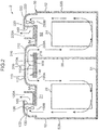
FIG. 2 schematically illustrates a gas supplying apparatus; -
FIG. 3 is a plan view schematically illustrating the gas supplying apparatus; -
FIG. 4 schematically illustrates an exemplary modification of the gas supplying apparatus; -
FIG. 5 schematically illustrates another exemplary modification of the gas supplying apparatus; and -
FIG. 6 schematically illustrates yet another exemplary modification of the gas supplying apparatus. - A gas supplying apparatus according to one embodiment of the present invention will now be described with reference to
FIGS. 1 to 3 .FIG. 1 illustrates a hydrogen station 1 including agas supplying apparatus 2. The hydrogen station 1 is for filling hydrogen gas to a tank of a tank mounted device such as a fuel cell vehicle 5. The hydrogen station 1 will be described with reference toFIG. 1 , and then thegas supplying apparatus 2 constituting a part of the hydrogen station 1 will be described in detail. - As illustrated in
FIG. 1 , the hydrogen station 1 includes thegas supplying apparatus 2, an accumulator unit 3, and adispenser 4 as main components. - The
gas supplying apparatus 2 compresses hydrogen gas to a predetermined high pressure state. The high pressure hydrogen gas generated by thegas supplying apparatus 2 is supplied to thedispenser 4 via the accumulator unit 3. Thegas supplying apparatus 2 includes areceiving unit 21 that receives hydrogen gas from a reservoir (not shown), acompressor 22 that compresses the received hydrogen gas to a predetermined high pressure state, a gas in-flow line 27, and a gas out-flow line 28. Thedispenser 4 and thereceiving unit 21 need not be provided to thegas supplying apparatus 2. - The
compressor 22 is, for example, a compressor that operates with a reciprocating motion (reciprocating compressor). Multiple stages of compressing chambers are provided inside thecompressor 22. As illustrated inFIG. 1 , a downstream end of areceiving line 26 is connected to an inlet of thecompressor 22. The hydrogen gas which is not yet compressed is supplied from thereceiving unit 21 to thecompressor 22 through thereceiving line 26. In each compressing chamber, the hydrogen gas suctioned into a cylinder through a suction port is boosted by a reciprocating piston, and the boosted hydrogen gas is exhausted through an discharge port. - For example, three or more stages of compressing chambers are provided inside the
compressor 22. Thecompressor 22 is a large compressor designed to operate in a range where the suction pressure is 1 MPa or lower and the discharge pressure is 80 MPa or higher and to exert a flowrate of about 300 Nm3/h or more (under a suction pressure of 1 MPa). Thus, a plurality ofaccumulators 23 can continuously and repetitively be filled with hydrogen gas within a predetermined time (for example, within an hour). - The accumulator unit 3 includes a plurality of (three, in the embodiment)
accumulators 23. Eachaccumulator 23 is a container that stores high pressure hydrogen gas discharged from thecompressor 22. Eachaccumulator 23 has a form of a capsule as illustrated inFIG. 1 and is designed to hold the same pressure (for example, 82 MPa). - The gas in-
flow line 27 interconnects thecompressor 22 and theaccumulator 23, thereby allowing the high pressure hydrogen gas to flow from thecompressor 22 to theaccumulators 23. Specifically, the upstream end of the gas in-flow line 27 is connected to the discharge port of thecompressor 22, and the downstream end of the gas in-flow line 27 branches by a number corresponding to the number of the accumulators 23 (branches into three lines in the embodiment). That is, the gas in-flow line 27 includes a main pipe and a plurality of branch pipes connected to the downstream end of the main pipe. Each branched portion (branch pipe) is connected to the inlet/outlet of theaccumulator 23. - As illustrated in
FIG. 1 , an on-offvalve 27A that allows hydrogen gas to flow therein or cuts off the hydrogen gas flow is provided to each branched portion of the gas in-flow line 27. By opening the on-offvalve 27A, the high pressure hydrogen gas discharged from thecompressor 22 flows into theaccumulator 23 through the gas in-flow line 27. - The gas out-
flow line 28 is a path for guiding the high pressure hydrogen gas stored in theaccumulator 23 to thedispenser 4. Specifically, the upstream portion of the gas out-flow line 28 branches by a number corresponding to the number of theaccumulators 23. That is, the gas out-flow line 28 includes a main pipe and a plurality of branch pipes connected to the upstream end of the main pipe. Each branched portion (branch pipe) is connected to a portion further in the downstream along the gas in-flow line 27 than the on-offvalve 27A. An on-offvalve 28A that allows hydrogen gas to flow therein or cuts off the hydrogen gas flow is provided to each branched portion (branch pipe) of the gas out-flow line 28. By opening the on-offvalve 28A with the on-offvalve 27A closed, the high pressure hydrogen gas stored in theaccumulator 23 is guided to thedispenser 4 through the gas out-flow line 28. - The
gas supplying apparatus 2 includes arefrigerator 24 used for cooling the compressed hydrogen gas. Therefrigerator 24 includes acoolant path 24B in which the coolant circulates, anevaporating unit 24A, a compressing unit, a condensing unit, and an expansion unit respectively provided on thecoolant path 24B. InFIG. 1 , the compressing unit, the condensing unit, and the expansion unit are collectively denoted by 24C for convenience. - As illustrated in
FIG. 1 , the evaporatingunit 24A is connected to abrine path 37. The evaporatingunit 24A exchanges heat between the coolant flowing in thecoolant path 24B and the brine flowing in thebrine path 37. The coolant evaporates and the brine is cooled. The cooled brine flows into a pre-cooler 35 provided to thedispenser 4 to exchange heat with the hydrogen gas that has flown into the pre-cooler 35 from theaccumulator 23. The compressed hydrogen gas is cooled by the brine. In this manner, therefrigerator 24 cools the brine, which is a secondary coolant, and is indirectly used for cooling the hydrogen gas. - The compressing unit of the
refrigerator 24 compresses the gaseous coolant flown out of the evaporatingunit 24A. The condensing unit exchanges heat between the coolant compressed by the compressing unit and air, thereby condensing the coolant. The expansion unit expands the liquid coolant flown out of the condensing unit. The coolant that has passed through the expansion unit flows into the evaporatingunit 24A. - The
gas supplying apparatus 2 further includes acontroller 29 that controls the operation of thegas supplying apparatus 2. For example, thecontroller 29 includes an integrated control-board that controls driving of thecompressor 22, opening and closing of the on-offvalves refrigerator 24, and driving of thedispenser 4. - The integrated control-board is connected to the components (the
compressor 22, therefrigerator 24, thedispenser 4, etc.) not by individual wires but by a field bus or a field network. The integrated control-board may be configured to communicate with a portable manipulating board, such as a tablet computer, over a radio. In such a case, various types of data may be displayed on the portable manipulating board and manipulating commands may be given to the components using the portable manipulating board. By using the portable manipulating board, the operating status of each component can be monitored and each component can be manipulated from any location in the hydrogen station 1. - The
dispenser 4 is for feeding high pressure hydrogen gas, which is supplied from theaccumulator 23 through the gas out-flow line 28, to the fuel cell vehicle 5. Thedispenser 4 includes the pre-cooler 35 for cooling hydrogen gas, and anozzle 4A for feeding the hydrogen gas cooled by the pre-cooler 35 to the fuel cell vehicle 5. Thenozzle 4A has such a shape that can be inserted in a supply port (not shown) of the tank of the fuel cell vehicle 5. - The pre-cooler 35 is, for example, a micro-channel heat exchanger and exchanges heat between the hydrogen gas and the brine as described above. The hydrogen gas cooled by the brine is fed to the tank of the fuel cell vehicle 5 through the
nozzle 4A. The brine that has absorbed heat from the hydrogen gas by heat exchange is sent to the evaporatingunit 24A by abrine pump 36 and cooled again by the coolant flowing in thecoolant path 24B. - As described above, direct heat exchange is not performed between the coolant of the
refrigerator 24 and the hydrogen gas, but cold energy generated in therefrigerator 24 is temporarily stored in the secondary coolant, such as brine, to efficiently cool the hydrogen gas. The secondary coolant is not limited to the brine, and for example, liquefied carbon dioxide can be used instead of the brine. - The configuration of the
gas supplying apparatus 2 will now be described in detail with reference toFIG. 2 . Thegas supplying apparatus 2 includes ahousing 50, a compressor intake duct (first intake duct) 110, a refrigerator intake duct (second intake duct) 210 which is an additional intake duct, a compressor exhaust duct (first exhaust duct) 120, a refrigerator exhaust duct (second exhaust duct) 220 which is an additional exhaust duct, acompressor rain guard 116, arefrigerator rain guard 216, acompressor fan 130, acompressor regulator 140, arefrigerator fan 230, arefrigerator regulator 240, and a joint 310. - The
housing 50 houses thecompressor 22 and therefrigerator 24. Thehousing 50 includes abottom wall 51, acircumferential wall 52, atop wall 54, and apartitioning wall 56. Thepartitioning wall 56 partitions the space surrounded by thecircumferential wall 52 and thetop wall 54 into a compressor space S1 where thecompressor 22 is housed and a refrigerator space S2 where therefrigerator 24 is housed. The compressor space S1 of the embodiment is made explosion-proof. - The
bottom wall 51 has a form of a flat plate. Thecompressor 22 and therefrigerator 24 are placed on thebottom wall 51. - The
circumferential wall 52 is connected to the rim of thebottom wall 51 and surrounds thecompressor 22 and therefrigerator 24. Thecircumferential wall 52 has a form of a square tube. Thecircumferential wall 52 hasaccess sections access section 52A is provided on a portion of thecircumferential wall 52 that defines the compressor space S1, and theaccess section 52B is provided on a portion of thecircumferential wall 52 that defines the refrigerator space S2. Specifically, theaccess section 52A is provided on the portion defining the compressor space S1 and in the opposite side of therefrigerator 24 with respect to thecompressor 22 in an arrangement direction, which is the direction along which thecompressor 22 and therefrigerator 24 are disposed. Theaccess section 52B is provided on the portion defining the refrigerator space S2 and is in the opposite side of thecompressor 22 with respect to therefrigerator 24 in the arrangement direction. In the embodiment, doors are used for theaccess sections circumferential wall 52. - The
top wall 54 is connected to the top of thecircumferential wall 52. Thetop wall 54 is provided with a compressor intake port (first intake port) 100A, a compressor exhaust port (first exhaust port) 100B, a refrigerator intake port (second intake port) 200A which is an additional intake port, and a refrigerator exhaust port (second exhaust port) 200B which is an additional exhaust port. Thecompressor intake port 100A is an opening through which ambient air is taken in to the compressor space S1 from outside thehousing 50. Thecompressor exhaust port 100B is an opening through which the air in the compressor space S1 is discharged to the outside of thehousing 50. Therefrigerator intake port 200A is an opening through which ambient air is taken in to the refrigerator space S2 from outside thehousing 50. Therefrigerator exhaust port 200B is an opening through which the air in the refrigerator space S2 is discharged to the outside of thehousing 50. Thecompressor intake port 100A is provided on a portion of thetop wall 54 that defines the compressor space S1 (the portion covering thecompressor 22 from above) and in the inner side in the arrangement direction. Thecompressor exhaust port 100B is provided on the portion of thetop wall 54 that defines the compressor space S1 and in the outer side in the arrangement direction. That is, thecompressor exhaust port 100B is located farther from the refrigerator space S2 and thepartitioning wall 56 than thecompressor intake port 100A. Therefrigerator intake port 200A is provided on a portion of thetop wall 54 that defines the refrigerator space S2 (the portion covering therefrigerator 24 from above) and in the inner side in the arrangement direction. Therefrigerator exhaust port 200B is provided on the portion of thetop wall 54 that defines the refrigerator space S2 and in the outer side in the arrangement direction. That is, therefrigerator exhaust port 200B is located farther from the compressor space S1 and thepartitioning wall 56 than therefrigerator intake port 200A. - The
partitioning wall 56 has a form of a flat plate. The bottom end of thepartitioning wall 56 is connected to thebottom wall 51. The top end of thepartitioning wall 56 is connected to a portion of thetop wall 54 at a location between thecompressor intake port 100A and therefrigerator intake port 200A. - The compressor intake duct 110 (hereinafter simply referred to as "
intake duct 110") is for guiding the ambient air suctioned through an ambientair intake port 109 to thecompressor intake port 100A. In the embodiment, the ambientair intake port 109 includes aduct inlet 110A of theintake duct 110, and aduct inlet 210A of therefrigerator intake duct 210. The ambient air intake port 109 (that is, theduct inlets intake ducts top wall 54 in the up-and-down direction (that is, in the direction of gravitational force). Theintake duct 110 includes anair introducing portion 112 that connects the ambientair intake port 109 and thecompressor intake port 100A. The ambient air suctioned through the ambientair intake port 109 is introduced to thecompressor intake port 100A via theair introducing portion 112. Theair introducing portion 112 is provided above thetop wall 54 and exists, longitudinally, within the dimension of thetop wall 54. Thus, theintake duct 110 does not exist laterally beyond thetop wall 54. The intake duct 110 (air introducing portion 112) extends upward from the top wall 54 (compressor intake port 100A) and then bends to be directed to a lateral direction. The bent portion directed to the lateral direction has a bottom face separated from thetop wall 54. - A compressor rain guard 116 (hereinafter simply referred to as "
rain guard 116") that prevents entry of rainwater from the ambientair intake port 109 toward thecompressor intake port 100A is provided in theair introducing portion 112. Therain guard 116 includes a baffle plate that stands perpendicular to the flow of the suctioned ambient air. - The compressor exhaust duct 120 (hereinafter simply referred to as "
exhaust duct 120") is for guiding the air in the compressor space S1 to the outside through thecompressor exhaust port 100B. Theexhaust duct 120 includes aduct outlet 120A which is a discharge port for discharging the air to the outside, and an air lead-outportion 122 that connects theduct outlet 120A and thecompressor exhaust port 100B. Theduct outlet 120A is provided on theexhaust duct 120 to open upward in an area overlapping thetop wall 54 in the up-and-down direction. The air lead-outportion 122 is provided above thetop wall 54 and exists, longitudinally, within the dimension of thetop wall 54. That is, theexhaust duct 120 does not exist laterally beyond thetop wall 54. Theexhaust duct 120 extends upward from the top wall 54 (compressor exhaust port 100B) and then bends to be directed to a lateral direction. The bending portion extends in the horizontal direction toward theintake duct 110. In the air lead-outportion 122, the air exhausted upward from thecompressor exhaust port 100B is guided horizontally and then upward to be discharged to the outside through theduct outlet 120A. - The
compressor fan 130 is provided in the air lead-outportion 122 of theexhaust duct 120. Thecompressor fan 130 generates an airflow that flows from thecompressor intake port 100A to thecompressor exhaust port 100B through the compressor space S1. Specifically, the airflow (indicated by an arrow inFIG. 2 ) generated by thecompressor fan 130 is such that the ambient air taken in through the ambientair intake port 109 flows through thecompressor intake port 100A, the bottom portion of the compressor space S1, and thecompressor exhaust port 100B to theduct outlet 120A. - The
compressor regulator 140 is provided in theexhaust duct 120 and in the downstream of thecompressor fan 130. Thecompressor regulator 140 allows passing of the airflow from thecompressor exhaust port 100B to theduct outlet 120A and restricts entry of rainwater from theduct outlet 120A toward thecompressor exhaust port 100B. The embodiment uses a louver as thecompressor regulator 140. In theexhaust duct 120, the airflow generated by thecompressor fan 130 also prevents entry of rainwater. - The refrigerator intake duct 210 (hereinafter simply referred to as "
intake duct 210") is for guiding the ambient air taken in through the ambientair intake port 109 to therefrigerator intake port 200A. Theintake duct 210 includes anair introducing portion 212 that connects the ambientair intake port 109 and therefrigerator intake port 200A. The ambient air taken in through the ambientair intake port 109 is introduced to therefrigerator intake port 200A via theair introducing portion 212. Theair introducing portion 212 is provided above thetop wall 54 and exists, longitudinally, within the dimension of thetop wall 54. That is, theintake duct 210 does not exist laterally beyond thetop wall 54. The intake duct 210 (air introducing portion 212) extends upward from the top wall 54 (refrigerator intake port 200A) and then bends to be directed to a lateral direction. The bent portion directed to the lateral direction has a bottom face separated from thetop wall 54. - A refrigerator rain guard 216 (hereinafter simply referred to as "
rain guard 216") that prevents entry of rainwater from the ambientair intake port 109 toward therefrigerator intake port 200A is provided in theair introducing portion 212. Therain guard 216 includes a baffle plate that stands perpendicular to the flow of the suctioned ambient air. - The refrigerator exhaust duct 220 (hereinafter simply referred to as "
exhaust duct 220") is for guiding the air in the refrigerator space S2 to the outside through therefrigerator exhaust port 200B. Theexhaust duct 220 includes aduct outlet 220A which is an additional discharge port for discharging air to the outside, and an air lead-outportion 222 that connects theduct outlet 220A and therefrigerator exhaust port 200B. Theduct outlet 220A is provided on theexhaust duct 220 to open upward in an area overlapping thetop wall 54 in the up-and-down direction. The air lead-outportion 222 is provided above thetop wall 54 and exists, longitudinally, within the dimension of thetop wall 54. That is, theexhaust duct 220 does not exist laterally beyond thetop wall 54. Theexhaust duct 220 extends upward from the top wall 54 (refrigerator exhaust port 200B) and then bends to be directed to a lateral direction. The bending portion extends in the horizontal direction toward theintake duct 210. In the air lead-outportion 222, the air exhausted upward from therefrigerator exhaust port 200B is guided horizontally and then upward to be discharged to the outside through theduct outlet 220A. - In the embodiment, the
exhaust duct 120, theintake duct 110, theintake duct 210, and theexhaust duct 220 are arranged in line on thetop wall 54 as illustrated inFIG. 3 . On thetop wall 54, there is a sufficient space in the direction perpendicular to the arrangement direction. This provides a sufficient working space for an operator or a sufficient space for installing other devices on thetop wall 54. - The
refrigerator fan 230 is provided in the air lead-outportion 222 of theexhaust duct 220. The airflow (the airflow indicated by an arrow inFIG. 2 ) generated by therefrigerator fan 230 is such that the ambient air taken in through the ambientair intake port 109 flows through therefrigerator intake port 200A, the bottom portion of the refrigerator space S2, and therefrigerator exhaust port 200B to theduct outlet 220A. - The
refrigerator regulator 240 is provided in theexhaust duct 220 and in the downstream of therefrigerator fan 230. Therefrigerator regulator 240 allows passing of the airflow from therefrigerator exhaust port 200B to theduct outlet 220A and restricts entry of rainwater from theduct outlet 220A toward therefrigerator exhaust port 200B. The embodiment uses a louver as therefrigerator regulator 240. In theexhaust duct 220, the airflow generated by therefrigerator fan 230 also prevents entry of rainwater. - The
intake duct 110 and theintake duct 210 are joined and thereby theduct inlet 110A and theadditional duct inlet 210A form a single ambientair intake port 109. The joined section is referred to as a joint 310. With the joint 310 joining theintake duct 110 and theintake duct 210, the required space for installing theintake duct 110 and theadditional intake duct 210 is small compared to a structure in which theintake duct 110 and theintake duct 210 are separately provided. The bottom face of theintake duct 110 and theintake duct 210 joined by the joint 310 is separated from thetop wall 54. The ambientair intake port 109 is provided on the bottom face separated from thetop wall 54. - As described above, the
gas supplying apparatus 2 of the embodiment includes theintake ports exhaust ports top wall 54. This allows a sufficient working space to be provided around the circumferential wall 52 (in particular, around theaccess sections duct outlets exhaust ducts compressor 22 to the surrounding of thehousing 50 is suppressed. The ambient air intake port 109 (that is, theduct inlets top wall 54 in the up-and-down direction. The noise emitted from the ambientair intake port 109 is reflected on thetop wall 54 and likely to propagate to the upper side of thehousing 50. This effectively reduces noise around thehousing 50. - Directing the ambient
air intake port 109 downward prevents rainwater from entering thecompressor intake port 100A and therefrigerator intake port 200A. Providing the duct inlets of theintake ducts air intake port 109 further reliably prevents rainwater from entering thecompressor intake port 100A and therefrigerator intake port 200A. - Furthermore, housing the
compressor 22 and therefrigerator 24 in asingle housing 50 reduces the area for installing thecompressor 22 and therefrigerator 24. - The
intake ducts exhaust ducts top wall 54 in the up-and-down direction. Thus, it is not necessary to secure a large installation space for thegas supplying apparatus 2. - Since the air lead-out
portion 122 horizontally extends toward theintake duct 210, a large installation space for theexhaust duct 120 is not necessary to be provided on the limited space of thetop wall 54. The same can be said for the air lead-outportion 222 of theexhaust duct 220. - It should be construed that the embodiments are disclosed herein by all means of illustration, not by means of limitation. The scope of the present invention is defined by the claims, not by the description on the embodiments, and includes all alterations and modifications within the scope of the meanings equivalent to the claims and within the scope of the claims.
- For example, the
duct outlet 120A of theexhaust duct 120 may be opened downward at a location overlapping thetop wall 54 in the up-and-down direction as illustrated inFIG. 4 . That is, theexhaust duct 120 having theduct outlet 120A opened downward may be provided not to exist laterally beyond thetop wall 54. In such a configuration, the noise emitted from theduct outlet 120A can effectively be suppressed.FIG. 4 is a schematic view when thegas supplying apparatus 2 is seen along the arrangement direction from the outer side of theaccess section 52A. The air lead-outportion 122 may guide the gas, which is exhausted upward through thecompressor exhaust port 100B, to the side opposite theintake duct 110. Theduct inlet 110A of the embodiment may be opened to the horizontal direction as long as theduct inlet 110A is disposed at a location overlapping thetop wall 54 in the up-and-down direction. The same can be said for theduct inlet 210A of therefrigerator intake duct 210, theduct outlet 220A of therefrigerator exhaust duct 220, and the air lead-outportion 222. - The
compressor intake duct 110 and therefrigerator intake duct 210 of the embodiment may be separated. That is, theduct inlet 110A of theintake duct 110 and theduct inlet 210A of theintake duct 210 may be provided separately. - The
compressor intake duct 110 and thecompressor exhaust duct 120 described in the embodiment may be used for a housing that houses only thecompressor 22. In this case, as illustrated inFIG. 5 , therefrigerator 24 is housed in a housing 50' provided separately from thehousing 50 that houses only thecompressor 22. Arefrigerator intake duct 210 and arefrigerator exhaust duct 220 are provided on the housing 50'. In this case, thecompressor intake duct 110 and therefrigerator intake duct 210 are provided separately. Thecompressor intake duct 110 exists, longitudinally, within the dimension of thetop wall 54 of thehousing 50. Therefrigerator intake duct 210 exists, longitudinally, within the dimension of a top wall 54' of the housing 50'. Theduct outlet 120A is opened upward or opened downward in an area overlapping thetop wall 54 in the up-and-down direction. Theduct inlet 110A of theintake duct 110 is disposed in an area overlapping thetop wall 54 in the up-and-down direction. Theexhaust duct 120 exists, longitudinally, within the dimension of thetop wall 54 of thehousing 50. - As illustrated in
FIG. 6 , the air lead-outportion 122 of thecompressor exhaust duct 120 provided on thetop wall 54 may have a bent section and an extending section. The same can be said for the air lead-outportion 222 of therefrigerator exhaust duct 220. With the air lead-outportions exhaust ducts exhaust ducts FIG. 6 . - To avoid interference with a member provided on the
top wall 54, the air lead-outportions top wall 54. In such a case, noise can still be reduced by opening theduct outlets top wall 54 in the up-and-down direction. - The
compressor exhaust port 100B may be provided at any place on thecircumferential wall 52 at a location higher than theaccess section 52A. Likewise, therefrigerator exhaust port 200B may be provided at any place on thecircumferential wall 52 at a location higher than theaccess section 52B. Theexhaust port 100B may be provided both on thecircumferential wall 52, at a location higher than theaccess section 52A, and on thetop wall 54. - In the embodiment, the
compressor rain guard 116 may be provided with a baffle plate of a different shape as long as it prevents entry of rainwater. The same can be said for therefrigerator rain guard 216. - The embodiment will now be summarized.
- (1) The embodiment, which is the gas supplying apparatus installed in premises of a facility that supplies hydrogen gas, includes a compressor that compresses the hydrogen gas, a housing that has a compressor space housing the compressor and an exhaust port for discharging air in the compressor space to outside, and an exhaust duct that guides the air in the compressor space to outside of the housing through the exhaust port. The housing includes a circumferential wall surrounding the compressor, and a top wall connected to a top of the circumferential wall. The circumferential wall includes access sections that allow an operator to enter inside the circumferential wall. The exhaust port is provided on at least one of the circumferential wall and the top wall at a location higher than the access sections. The exhaust duct includes a discharge port for discharging air exhausted from the exhaust port to the outside. The discharge port is opened upward or opened downward in an area overlapping the top wall in an up-and-down direction.
- The gas supplying apparatus is such that the exhaust port is provided on at least one of the circumferential wall and the top wall at a portion higher than the access section. This allows a sufficient working space to be provided around the circumferential wall in a portion below the exhaust port. The discharge port of the exhaust duct is opened upward or opened downward in an area overlapping the top wall in the up-and-down direction. This suppresses the noise generated by driving the compressor.
- (2) The gas supplying apparatus is such that an intake port that takes in ambient air to the compressor space may be provided on at least one of the circumferential wall and the top wall at a location higher than the access section. The gas supplying apparatus may further include an intake duct that guides ambient air into the compressor space through the intake port. The duct inlet of the intake duct is disposed in an area overlapping the top wall in the up-and-down direction.
- In this embodiment, the noise generated by the compressor and emitted downward from the duct inlet is reflected on the top wall. This suppresses propagation of the noise to the surrounding of the housing.
- (3) The duct inlet may be opened downward at a location overlapping the top wall in the up-and-down direction.
- In this embodiment, the noise emitted from the duct inlet is reflected on the top wall, and thus propagation of the noise to the surrounding of the housing is further reliably suppressed.
- (4) The exhaust port of the gas supplying apparatus may be provided on the top wall. The exhaust duct may further include an air lead-out portion that extends in a horizontal direction to connect the exhaust port and the discharge port. The air lead-out portion may be provided above the top wall and exists, longitudinally, within the dimension of the top wall.
- In this embodiment, it is not necessary to secure a large installation space for the gas supplying apparatus including the exhaust duct.
- (5) The gas supplying apparatus may further include a refrigerator that cools hydrogen gas that is discharged from the compressor and is supplied to a dispenser for feeding the hydrogen gas to a tank of a tank mounted device, an additional exhaust duct that is provided separately from the exhaust duct and connected to the housing, and an additional intake duct that is provided separately from the intake duct and connected to the housing. The housing may further include a partitioning wall that partitions a space surrounded by the circumferential wall and the top wall into the compressor space and a refrigerator space in which the refrigerator is housed, an additional exhaust port that is provided separately from the exhaust port and for discharging air in the refrigerator space to outside, and an additional intake port that is provided separately from the intake port and for taking in ambient air to the refrigerator. The additional exhaust port and the additional intake port may be provided on a portion of the top wall that defines the refrigerator space. The additional exhaust duct may include an additional discharge port for discharging air, exhausted from the additional exhaust port, to the outside. The additional discharge port is opened upward or opened downward in an area overlapping the top wall in the up-and-down direction. The additional intake duct may include an additional duct inlet for taking in ambient air to be supplied to the additional intake port. The additional duct inlet may be provided in an area overlapping the top wall in the up-and-down direction.
- In this embodiment, the compressor and the refrigerator are housed in a single housing, and therefore the installation area for the compressor and the refrigerator is smaller than that of a configuration in which the compressor and the refrigerator are housed in different housings. The housing has the partitioning wall, so that the compressor space and the refrigerator space can be configured differently. For example, only the compressor space may be made explosion-proof. The additional discharge port is opened upward or opened downward in an area overlapping the top wall in the up-and-down direction. At the same time, the additional duct inlet is provided in an area overlapping the top wall in the up-and-down direction. This suppresses propagation of noise generated by driving the compressor and the refrigerator to the surrounding of the housing.
- (6) The gas supplying apparatus may further include a joint that joins the duct inlet and the additional duct inlet to form a single ambient air intake port.
- In this embodiment, the space required for installing the intake duct can be made small compared to a structure in which the intake duct and the additional intake duct are separated. This further reliably prevents water from entering the duct inlet.
- (7) The exhaust duct, the intake duct, the additional intake duct, and the additional exhaust duct may be disposed in line.
- In this embodiment, a sufficient working space for an operator or a sufficient space for installing other devices on the top wall can be provided.
- (8) The gas supplying apparatus may further include a compressor rain guard that is provided in the intake duct to prevent entry of rainwater from the duct inlet toward the intake port, and a refrigerator rain guard that is provided in the additional intake duct to prevent entry of rainwater from the additional duct inlet toward the additional intake port.
- In this embodiment, water is further reliably prevented from entering the intake ports.
- (9) The gas supplying apparatus may further include a compressor fan that is provided in the exhaust duct to generate an airflow flowing from the intake port to the exhaust port, and a refrigerator fan that is provided in the additional exhaust duct to generate an airflow flowing from the additional intake port to the additional exhaust port.
- In this embodiment, rainwater entering the exhaust duct along with the airflow generated by the fan can be prevented. In particular, this configuration is preferable if the discharge port and the additional discharge port are opened upward.
- (10) The gas supplying apparatus may further include a compressor regulator that is provided in the exhaust duct and in downstream of the compressor fan to allow passing of the airflow from the exhaust port to the discharge port and restrict entry of rainwater from the discharge port toward the exhaust port, and a refrigerator regulator that is provided in the additional exhaust duct and in downstream of the refrigerator fan to allow passing of the airflow from the additional exhaust port to the additional discharge port and restrict entry of rainwater from the additional discharge port toward the additional exhaust port.
- In this embodiment, water (such as rainwater) is further reliably prevented from entering the exhaust ports.
- As described above, the gas supplying apparatus that is provided with a working space for an operator around a housing that houses the compressor or the refrigerator and reduces the noise generated by the compressor or the refrigerator can be provided.
- This application is based on Japanese Patent application No.
2017-212673 - Although the present invention has been fully described by way of example with reference to the accompanying drawings, it is to be understood that various changes and modifications will be apparent to those skilled in the art. Therefore, unless otherwise such changes and modifications depart from the scope of the present invention hereinafter defined, they should be construed as being included therein.
- A gas supplying apparatus includes a compressor, a housing having an exhaust port, and an exhaust duct. The housing has a circumferential wall and a top wall. The circumferential wall has an access section. The exhaust port is provided on at least one of the circumferential wall and the top wall at a location higher than the access section. The exhaust duct includes a discharge port for discharging the air, exhausted from the exhaust port, to the outside. The discharge port is opened upward or opened downward in an area overlapping the top wall in an up-and-down direction.
Claims (10)
- A gas supplying apparatus provided in premises of a facility that supplies hydrogen gas, the gas supplying apparatus comprising:a compressor (22) that compresses the hydrogen gas;a housing (50) that has a compressor space (S1) housing the compressor (22) and an exhaust port (100B) for discharging air in the compressor space (S1) to outside; andan exhaust duct (120) that guides air in the compressor space (S1) to outside of the housing (50) through the exhaust port (100B),wherein the housing (50) includes a circumferential wall (52) surrounding the compressor (22), and a top wall (54) connected to a top of the circumferential wall (52),the circumferential wall (52) includes access sections (52A, 52B) that allow an operator to enter inside the circumferential wall (52),the exhaust port (100B) is provided on at least one of the circumferential wall (52) and the top wall (54), the exhaust port (100B) being provided at a location higher than the access sections (52A, 52B),the exhaust duct (120) includes a discharge port (120A) for discharging air exhausted from the exhaust port (100B) to the outside, andthe discharge port (120A) is opened upward or opened downward in an area overlapping the top wall (54) in an up-and-down direction.
- The gas supplying apparatus according to claim 1, further comprising:an intake port (100A) provided on at least one of the circumferential wall (52) and the top wall (54) to take in ambient air to the compressor space (S1), the intake port (100A) being located higher than the access sections (52A, 52B); andan intake duct (110) that has a duct inlet (110A) and guides ambient air to the compressor space (S1) through the intake port (100A),wherein the duct inlet (110A) of the intake duct (110) is disposed in an area overlapping the top wall (54) in the up-and-down direction.
- The gas supplying apparatus according to claim 2, wherein the duct inlet (110A) is opened downward at a location overlapping the top wall (54) in the up-and-down direction.
- The gas supplying apparatus according to claim 2, wherein
the exhaust port (100B) is provided on the top wall (54),
the exhaust duct (120) further includes an air lead-out portion (122) that extends horizontally and connects the exhaust port (100B) and the discharge port (120A), and
the air lead-out portion (122) is provided above the top wall (54) and exists, longitudinally, within a dimension of the top wall (54). - The gas supplying apparatus according to any one of claims 1 to 4, further comprising:a refrigerator (24) that cools hydrogen gas that is discharged from the compressor (22) and supplied to a dispenser (4) that feeds the hydrogen gas to a tank of a tank mounted device;an additional exhaust duct (220) that is provided separately from the exhaust duct (120) and connected to the housing (50); andan additional intake duct (210) that is provided separately from the intake duct (110) and connected to the housing (50),wherein the housing (50) includesa partitioning wall (56) that partitions a space surrounded by the circumferential wall (52) and the top wall (54) into the compressor space (S1) and a refrigerator space (S2) in which the refrigerator (24) is housed,an additional exhaust port (200B) that is provided separately from the exhaust port (100B) and for discharging air in the refrigerator space (S2) to outside, andan additional intake port (200A) that is provided separately from the intake port (100A) and for taking in ambient air to the refrigerator space (S2),the additional exhaust port (200B) and the additional intake port (200A) are provided on a portion of the top wall (54), the portion defining the refrigerator space (S2),the additional exhaust duct (220) includes an additional discharge port (220A) for discharging air, exhausted from the additional exhaust port (200B), to the outside,the additional discharge port (220A) is opened upward or opened downward in an area overlapping the top wall (54) in the up-and-down direction,the additional intake duct (210) includes an additional duct inlet (210A) for taking in ambient air to be supplied to the additional intake port (200A), andthe additional duct inlet (210A) is provided in an area overlapping the top wall (54) in the up-and-down direction.
- The gas supplying apparatus according to claim 5, further comprising a joint (310) that joins the duct inlet (110A) and the additional duct inlet (210A) to form a single ambient air intake port (109).
- The gas supplying apparatus according to claim 5, wherein the exhaust duct (120), the intake duct (110), the additional intake duct (210), and the additional exhaust duct (220) are disposed in line.
- The gas supplying apparatus according to claim 5, further comprising:a compressor rain guard (116) that is provided in the intake duct (110) to prevent entry of rainwater from the duct inlet (110A) toward the intake port (100A); anda refrigerator rain guard (216) that is provided in the additional intake duct (210) to prevent entry of rainwater from the additional duct inlet (210A) toward the additional intake port (200A).
- The gas supplying apparatus according to claim 5, further comprising:a compressor fan (130) that is provided in the exhaust duct (120) to generate an airflow flowing from the intake port (100A) to the exhaust port (100B); anda refrigerator fan (230) that is provided in the additional exhaust duct (220) to generate an airflow flowing from the additional intake port (200A) to the additional exhaust port (200B).
- The gas supplying apparatus according to claim 9, further comprising:a compressor regulator (140) that is provided in the exhaust duct (120) and in downstream of the compressor fan (130) to allow passing of the airflow from the exhaust port (100B) to the discharge port (120A) and restrict entry of rainwater from the discharge port (120A) toward the exhaust port (100B); anda refrigerator regulator (240) that is provided in the additional exhaust duct (220) and in downstream of the refrigerator fan (230) to allow passing of the airflow from the additional exhaust port (200B) to the additional discharge port (220A) and restrict entry of rainwater from the additional discharge port (220A) toward the additional exhaust port (200B).
Applications Claiming Priority (1)
| Application Number | Priority Date | Filing Date | Title |
|---|---|---|---|
| JP2017212673A JP6810015B2 (en) | 2017-11-02 | 2017-11-02 | Gas supply device |
Publications (2)
| Publication Number | Publication Date |
|---|---|
| EP3480459A1 true EP3480459A1 (en) | 2019-05-08 |
| EP3480459B1 EP3480459B1 (en) | 2020-02-19 |
Family
ID=63914891
Family Applications (1)
| Application Number | Title | Priority Date | Filing Date |
|---|---|---|---|
| EP18201260.9A Active EP3480459B1 (en) | 2017-11-02 | 2018-10-18 | Gas supplying apparatus |
Country Status (6)
| Country | Link |
|---|---|
| US (1) | US11015589B2 (en) |
| EP (1) | EP3480459B1 (en) |
| JP (1) | JP6810015B2 (en) |
| KR (1) | KR102130606B1 (en) |
| CN (1) | CN109751512B (en) |
| CA (1) | CA3021167C (en) |
Families Citing this family (21)
| Publication number | Priority date | Publication date | Assignee | Title |
|---|---|---|---|---|
| CN214247597U (en) | 2020-12-11 | 2021-09-21 | 烟台杰瑞石油装备技术有限公司 | Fracturing device |
| US11680474B2 (en) | 2019-06-13 | 2023-06-20 | Yantai Jereh Petroleum Equipment & Technologies Co., Ltd. | Fracturing apparatus and control method thereof, fracturing system |
| US12173594B2 (en) | 2019-06-13 | 2024-12-24 | Yantai Jereh Petroleum Equipment & Technologies Co., Ltd. | Fracturing system |
| CN112983381A (en) * | 2021-04-20 | 2021-06-18 | 烟台杰瑞石油装备技术有限公司 | Fracturing equipment, control method thereof and fracturing system |
| US12326074B2 (en) | 2019-06-13 | 2025-06-10 | Yantai Jereh Petroleum Equipment & Technologies Co., Ltd. | Fracturing apparatus and control method thereof, fracturing system |
| US11746636B2 (en) * | 2019-10-30 | 2023-09-05 | Yantai Jereh Petroleum Equipment & Technologies Co., Ltd. | Fracturing apparatus and control method thereof, fracturing system |
| CN110118127A (en) | 2019-06-13 | 2019-08-13 | 烟台杰瑞石油装备技术有限公司 | A kind of electricity drives the power supply semitrailer of fracturing unit |
| CN214887011U (en) | 2020-11-24 | 2021-11-26 | 烟台杰瑞石油装备技术有限公司 | Fracturing system |
| US12234712B2 (en) | 2019-09-20 | 2025-02-25 | Yantai Jereh Petroleum Equipment & Technologies Co., Ltd. | Adaptive mobile power generation system |
| US12313059B2 (en) | 2019-10-30 | 2025-05-27 | Yantai Jereh Petroleum Equipment & Technologies Co., Ltd. | Variable-speed integrated machine and wellsite apparatus |
| JP2022030435A (en) * | 2020-08-07 | 2022-02-18 | 株式会社神戸製鋼所 | Gas supply device |
| US11662384B2 (en) | 2020-11-13 | 2023-05-30 | Yantai Jereh Petroleum Equipment & Technologies Co., Ltd. | Motor malfunction monitoring device, drive motor system and motor malfunction monitoring method |
| CA3157232A1 (en) | 2020-11-24 | 2022-05-24 | Yantai Jereh Petroleum Equipment & Technologies Co., Ltd. | Fracturing system |
| CN113315111B (en) | 2021-04-26 | 2023-01-24 | 烟台杰瑞石油装备技术有限公司 | Power supply method and power supply system |
| CN215870792U (en) | 2021-10-12 | 2022-02-18 | 烟台杰瑞石油装备技术有限公司 | Power supply system for wellsite electric drive equipment |
| CA3179258A1 (en) | 2021-10-14 | 2023-04-14 | Yantai Jereh Petroleum Equipment & Technologies Co., Ltd. | A fracturing device driven by a variable-frequency adjustable-speed integrated machine and a well site layout |
| CN114198635B (en) * | 2021-12-09 | 2023-02-28 | 上海氢枫能源技术有限公司 | An intelligent hydrogenation system and method |
| US12272987B2 (en) | 2022-02-15 | 2025-04-08 | Yantai Jereh Petroleum Equipment & Technologies Co., Ltd. | Electrically-driven pumping system and driving method thereof |
| US12203353B2 (en) | 2022-02-16 | 2025-01-21 | Yantai Jereh Petroleum Equipment & Technologies Co., Ltd. | Electrically-driven fracturing system |
| BE1030350B1 (en) * | 2022-03-16 | 2023-10-17 | Atlas Copco Airpower Nv | Air-cooled pressure forming device |
| CN119309146B (en) * | 2023-07-11 | 2025-11-21 | 中国石油化工股份有限公司 | Hydrogen gas emptying system |
Citations (5)
| Publication number | Priority date | Publication date | Assignee | Title |
|---|---|---|---|---|
| CH676951A5 (en) * | 1988-08-12 | 1991-03-28 | Sulzer Ag | Vehicle gas tank filling appliance - has second internal housing for compressor-motor group |
| JP2011132876A (en) | 2009-12-24 | 2011-07-07 | Hitachi Plant Technologies Ltd | Hydrogen compression device and hydrogen gas leakage monitoring system |
| JP2015158213A (en) * | 2014-02-21 | 2015-09-03 | 株式会社神戸製鋼所 | gas supply system and hydrogen station |
| WO2016067780A1 (en) * | 2014-10-31 | 2016-05-06 | 株式会社神戸製鋼所 | Hydrogen station |
| JP2017212673A (en) | 2016-05-27 | 2017-11-30 | 日本電信電話株式会社 | Radio communication method and radio communication system |
Family Cites Families (21)
| Publication number | Priority date | Publication date | Assignee | Title |
|---|---|---|---|---|
| JPS5021195B2 (en) * | 1971-09-22 | 1975-07-21 | ||
| JPS5166151A (en) * | 1974-12-05 | 1976-06-08 | Matsushita Seiko Kk | KANKISOCHI |
| JPH0422195Y2 (en) * | 1986-07-17 | 1992-05-20 | ||
| US5643077A (en) * | 1995-06-16 | 1997-07-01 | Ayer; Jacqueline | Continually optimized, variable flow rate ventilation system |
| DE19933791A1 (en) * | 1999-07-20 | 2001-02-01 | Linde Gas Ag | Method and filling station for refueling a vehicle tank with a gaseous fuel |
| JP2001342962A (en) * | 2000-05-31 | 2001-12-14 | Chiyoda Security Service:Kk | Gas filling equipment |
| DE10117791A1 (en) | 2001-04-10 | 2002-10-17 | Boge Kompressoren | Compressor system for producing compressed air comprises a compressor stage arranged in a sound-proof compressor chamber (26) within a housing but spatially removed from a drive motor |
| US6793699B2 (en) * | 2001-09-05 | 2004-09-21 | Dennis D. Coleman | Continuous tracer generation apparatus |
| KR100519309B1 (en) * | 2003-06-03 | 2005-10-10 | 엘지전자 주식회사 | air conditioning system with fresh air supplying device |
| KR100577256B1 (en) * | 2004-01-28 | 2006-05-10 | 엘지전자 주식회사 | Ventilation combined air cleaner |
| JP5021195B2 (en) * | 2005-06-30 | 2012-09-05 | 株式会社日立産機システム | Package type compressor |
| US7380544B2 (en) * | 2006-05-19 | 2008-06-03 | Modine Manufacturing Company | EGR cooler with dual coolant loop |
| JP5397107B2 (en) | 2009-09-09 | 2014-01-22 | 株式会社デンソー | Humidity control equipment |
| US20110139097A1 (en) * | 2009-12-11 | 2011-06-16 | Anthony Scott Brown | Gas generation and management system |
| US20130084794A1 (en) * | 2011-09-29 | 2013-04-04 | Vitali Victor Lissianski | Systems and methods for providing utilities and carbon dioxide |
| US20130233388A1 (en) * | 2012-03-06 | 2013-09-12 | General Electric Company | Modular compressed natural gas system |
| CN203082528U (en) * | 2012-12-25 | 2013-07-24 | 煤炭科学研究总院 | Automatic rapid filling system |
| KR101337439B1 (en) * | 2013-07-16 | 2013-12-10 | 권우득 | Ventilation system for bathroom |
| WO2015125585A1 (en) * | 2014-02-21 | 2015-08-27 | 株式会社神戸製鋼所 | Gas supply system and hydrogen station |
| US9404623B2 (en) * | 2014-02-25 | 2016-08-02 | General Electric Company | Modular compressed natural gas system for use at a wellsite |
| JP6659401B2 (en) * | 2016-02-29 | 2020-03-04 | 株式会社神戸製鋼所 | Combustible gas supply unit and barrier |
-
2017
- 2017-11-02 JP JP2017212673A patent/JP6810015B2/en not_active Expired - Fee Related
-
2018
- 2018-10-16 US US16/161,563 patent/US11015589B2/en not_active Expired - Fee Related
- 2018-10-17 CA CA3021167A patent/CA3021167C/en active Active
- 2018-10-18 EP EP18201260.9A patent/EP3480459B1/en active Active
- 2018-10-29 KR KR1020180129609A patent/KR102130606B1/en not_active Expired - Fee Related
- 2018-10-30 CN CN201811279298.9A patent/CN109751512B/en not_active Expired - Fee Related
Patent Citations (5)
| Publication number | Priority date | Publication date | Assignee | Title |
|---|---|---|---|---|
| CH676951A5 (en) * | 1988-08-12 | 1991-03-28 | Sulzer Ag | Vehicle gas tank filling appliance - has second internal housing for compressor-motor group |
| JP2011132876A (en) | 2009-12-24 | 2011-07-07 | Hitachi Plant Technologies Ltd | Hydrogen compression device and hydrogen gas leakage monitoring system |
| JP2015158213A (en) * | 2014-02-21 | 2015-09-03 | 株式会社神戸製鋼所 | gas supply system and hydrogen station |
| WO2016067780A1 (en) * | 2014-10-31 | 2016-05-06 | 株式会社神戸製鋼所 | Hydrogen station |
| JP2017212673A (en) | 2016-05-27 | 2017-11-30 | 日本電信電話株式会社 | Radio communication method and radio communication system |
Also Published As
| Publication number | Publication date |
|---|---|
| KR20190050281A (en) | 2019-05-10 |
| EP3480459B1 (en) | 2020-02-19 |
| JP2019086037A (en) | 2019-06-06 |
| CA3021167A1 (en) | 2019-05-02 |
| US11015589B2 (en) | 2021-05-25 |
| CA3021167C (en) | 2020-08-25 |
| KR102130606B1 (en) | 2020-07-06 |
| CN109751512B (en) | 2020-10-09 |
| CN109751512A (en) | 2019-05-14 |
| JP6810015B2 (en) | 2021-01-06 |
| US20190128265A1 (en) | 2019-05-02 |
Similar Documents
| Publication | Publication Date | Title |
|---|---|---|
| EP3480459B1 (en) | Gas supplying apparatus | |
| US10801671B2 (en) | Gas supply system and hydrogen station | |
| KR101970904B1 (en) | Hydrogen station | |
| JP5661057B2 (en) | Hydrogen station | |
| CN101952172B (en) | Systems and methods for ventilating blast zones of spacecraft | |
| KR101543945B1 (en) | Outdoor unit for refrigeration device | |
| JP2013024287A (en) | Hydrogen gas filling device | |
| WO2015125585A1 (en) | Gas supply system and hydrogen station | |
| JP7083660B2 (en) | Combustible gas supply unit and hydrogen station | |
| JP2015158213A (en) | gas supply system and hydrogen station | |
| US10711946B2 (en) | Combustible gas supply unit and hydrogen station | |
| US9644853B2 (en) | Packaged engine working machine | |
| EP2990242A1 (en) | Air conditioning device for vehicle | |
| US5964659A (en) | Ventilated enclosure for gas cylinders and manifolds | |
| JP7057100B2 (en) | Gas supply device | |
| JP6077293B2 (en) | In-vehicle purge system | |
| JP2003261200A (en) | Beverage dispenser | |
| PT2292509E (en) | Submarine with a compactor | |
| KR20180003033U (en) | Gas valve unit for generator |
Legal Events
| Date | Code | Title | Description |
|---|---|---|---|
| PUAI | Public reference made under article 153(3) epc to a published international application that has entered the european phase |
Free format text: ORIGINAL CODE: 0009012 |
|
| STAA | Information on the status of an ep patent application or granted ep patent |
Free format text: STATUS: THE APPLICATION HAS BEEN PUBLISHED |
|
| AK | Designated contracting states |
Kind code of ref document: A1 Designated state(s): AL AT BE BG CH CY CZ DE DK EE ES FI FR GB GR HR HU IE IS IT LI LT LU LV MC MK MT NL NO PL PT RO RS SE SI SK SM TR |
|
| AX | Request for extension of the european patent |
Extension state: BA ME |
|
| STAA | Information on the status of an ep patent application or granted ep patent |
Free format text: STATUS: REQUEST FOR EXAMINATION WAS MADE |
|
| 17P | Request for examination filed |
Effective date: 20190614 |
|
| RBV | Designated contracting states (corrected) |
Designated state(s): AL AT BE BG CH CY CZ DE DK EE ES FI FR GB GR HR HU IE IS IT LI LT LU LV MC MK MT NL NO PL PT RO RS SE SI SK SM TR |
|
| GRAP | Despatch of communication of intention to grant a patent |
Free format text: ORIGINAL CODE: EPIDOSNIGR1 |
|
| STAA | Information on the status of an ep patent application or granted ep patent |
Free format text: STATUS: GRANT OF PATENT IS INTENDED |
|
| RIC1 | Information provided on ipc code assigned before grant |
Ipc: F04B 39/12 20060101ALI20190705BHEP Ipc: F04B 39/06 20060101ALI20190705BHEP Ipc: F17C 5/00 20060101ALI20190705BHEP Ipc: F04B 39/00 20060101AFI20190705BHEP |
|
| INTG | Intention to grant announced |
Effective date: 20190806 |
|
| RIN1 | Information on inventor provided before grant (corrected) |
Inventor name: HASHIMOTO, KOICHIRO Inventor name: WASHIO, TAKUYA Inventor name: NAGURA, KENJI Inventor name: FUJISAWA, AKITOSHI Inventor name: WADA, DAISUKE |
|
| GRAS | Grant fee paid |
Free format text: ORIGINAL CODE: EPIDOSNIGR3 |
|
| GRAA | (expected) grant |
Free format text: ORIGINAL CODE: 0009210 |
|
| STAA | Information on the status of an ep patent application or granted ep patent |
Free format text: STATUS: THE PATENT HAS BEEN GRANTED |
|
| AK | Designated contracting states |
Kind code of ref document: B1 Designated state(s): AL AT BE BG CH CY CZ DE DK EE ES FI FR GB GR HR HU IE IS IT LI LT LU LV MC MK MT NL NO PL PT RO RS SE SI SK SM TR |
|
| REG | Reference to a national code |
Ref country code: CH Ref legal event code: EP |
|
| REG | Reference to a national code |
Ref country code: DE Ref legal event code: R096 Ref document number: 602018002547 Country of ref document: DE |
|
| REG | Reference to a national code |
Ref country code: AT Ref legal event code: REF Ref document number: 1235275 Country of ref document: AT Kind code of ref document: T Effective date: 20200315 |
|
| REG | Reference to a national code |
Ref country code: IE Ref legal event code: FG4D |
|
| REG | Reference to a national code |
Ref country code: NL Ref legal event code: MP Effective date: 20200219 |
|
| PG25 | Lapsed in a contracting state [announced via postgrant information from national office to epo] |
Ref country code: RS Free format text: LAPSE BECAUSE OF FAILURE TO SUBMIT A TRANSLATION OF THE DESCRIPTION OR TO PAY THE FEE WITHIN THE PRESCRIBED TIME-LIMIT Effective date: 20200219 Ref country code: NO Free format text: LAPSE BECAUSE OF FAILURE TO SUBMIT A TRANSLATION OF THE DESCRIPTION OR TO PAY THE FEE WITHIN THE PRESCRIBED TIME-LIMIT Effective date: 20200519 Ref country code: FI Free format text: LAPSE BECAUSE OF FAILURE TO SUBMIT A TRANSLATION OF THE DESCRIPTION OR TO PAY THE FEE WITHIN THE PRESCRIBED TIME-LIMIT Effective date: 20200219 |
|
| REG | Reference to a national code |
Ref country code: LT Ref legal event code: MG4D |
|
| PG25 | Lapsed in a contracting state [announced via postgrant information from national office to epo] |
Ref country code: LV Free format text: LAPSE BECAUSE OF FAILURE TO SUBMIT A TRANSLATION OF THE DESCRIPTION OR TO PAY THE FEE WITHIN THE PRESCRIBED TIME-LIMIT Effective date: 20200219 Ref country code: SE Free format text: LAPSE BECAUSE OF FAILURE TO SUBMIT A TRANSLATION OF THE DESCRIPTION OR TO PAY THE FEE WITHIN THE PRESCRIBED TIME-LIMIT Effective date: 20200219 Ref country code: HR Free format text: LAPSE BECAUSE OF FAILURE TO SUBMIT A TRANSLATION OF THE DESCRIPTION OR TO PAY THE FEE WITHIN THE PRESCRIBED TIME-LIMIT Effective date: 20200219 Ref country code: IS Free format text: LAPSE BECAUSE OF FAILURE TO SUBMIT A TRANSLATION OF THE DESCRIPTION OR TO PAY THE FEE WITHIN THE PRESCRIBED TIME-LIMIT Effective date: 20200619 Ref country code: GR Free format text: LAPSE BECAUSE OF FAILURE TO SUBMIT A TRANSLATION OF THE DESCRIPTION OR TO PAY THE FEE WITHIN THE PRESCRIBED TIME-LIMIT Effective date: 20200520 Ref country code: BG Free format text: LAPSE BECAUSE OF FAILURE TO SUBMIT A TRANSLATION OF THE DESCRIPTION OR TO PAY THE FEE WITHIN THE PRESCRIBED TIME-LIMIT Effective date: 20200519 |
|
| PG25 | Lapsed in a contracting state [announced via postgrant information from national office to epo] |
Ref country code: NL Free format text: LAPSE BECAUSE OF FAILURE TO SUBMIT A TRANSLATION OF THE DESCRIPTION OR TO PAY THE FEE WITHIN THE PRESCRIBED TIME-LIMIT Effective date: 20200219 |
|
| PG25 | Lapsed in a contracting state [announced via postgrant information from national office to epo] |
Ref country code: SK Free format text: LAPSE BECAUSE OF FAILURE TO SUBMIT A TRANSLATION OF THE DESCRIPTION OR TO PAY THE FEE WITHIN THE PRESCRIBED TIME-LIMIT Effective date: 20200219 Ref country code: PT Free format text: LAPSE BECAUSE OF FAILURE TO SUBMIT A TRANSLATION OF THE DESCRIPTION OR TO PAY THE FEE WITHIN THE PRESCRIBED TIME-LIMIT Effective date: 20200712 Ref country code: SM Free format text: LAPSE BECAUSE OF FAILURE TO SUBMIT A TRANSLATION OF THE DESCRIPTION OR TO PAY THE FEE WITHIN THE PRESCRIBED TIME-LIMIT Effective date: 20200219 Ref country code: LT Free format text: LAPSE BECAUSE OF FAILURE TO SUBMIT A TRANSLATION OF THE DESCRIPTION OR TO PAY THE FEE WITHIN THE PRESCRIBED TIME-LIMIT Effective date: 20200219 Ref country code: EE Free format text: LAPSE BECAUSE OF FAILURE TO SUBMIT A TRANSLATION OF THE DESCRIPTION OR TO PAY THE FEE WITHIN THE PRESCRIBED TIME-LIMIT Effective date: 20200219 Ref country code: RO Free format text: LAPSE BECAUSE OF FAILURE TO SUBMIT A TRANSLATION OF THE DESCRIPTION OR TO PAY THE FEE WITHIN THE PRESCRIBED TIME-LIMIT Effective date: 20200219 Ref country code: CZ Free format text: LAPSE BECAUSE OF FAILURE TO SUBMIT A TRANSLATION OF THE DESCRIPTION OR TO PAY THE FEE WITHIN THE PRESCRIBED TIME-LIMIT Effective date: 20200219 Ref country code: ES Free format text: LAPSE BECAUSE OF FAILURE TO SUBMIT A TRANSLATION OF THE DESCRIPTION OR TO PAY THE FEE WITHIN THE PRESCRIBED TIME-LIMIT Effective date: 20200219 Ref country code: DK Free format text: LAPSE BECAUSE OF FAILURE TO SUBMIT A TRANSLATION OF THE DESCRIPTION OR TO PAY THE FEE WITHIN THE PRESCRIBED TIME-LIMIT Effective date: 20200219 |
|
| REG | Reference to a national code |
Ref country code: AT Ref legal event code: MK05 Ref document number: 1235275 Country of ref document: AT Kind code of ref document: T Effective date: 20200219 |
|
| REG | Reference to a national code |
Ref country code: DE Ref legal event code: R097 Ref document number: 602018002547 Country of ref document: DE |
|
| PLBE | No opposition filed within time limit |
Free format text: ORIGINAL CODE: 0009261 |
|
| STAA | Information on the status of an ep patent application or granted ep patent |
Free format text: STATUS: NO OPPOSITION FILED WITHIN TIME LIMIT |
|
| 26N | No opposition filed |
Effective date: 20201120 |
|
| PG25 | Lapsed in a contracting state [announced via postgrant information from national office to epo] |
Ref country code: AT Free format text: LAPSE BECAUSE OF FAILURE TO SUBMIT A TRANSLATION OF THE DESCRIPTION OR TO PAY THE FEE WITHIN THE PRESCRIBED TIME-LIMIT Effective date: 20200219 Ref country code: IT Free format text: LAPSE BECAUSE OF FAILURE TO SUBMIT A TRANSLATION OF THE DESCRIPTION OR TO PAY THE FEE WITHIN THE PRESCRIBED TIME-LIMIT Effective date: 20200219 |
|
| PG25 | Lapsed in a contracting state [announced via postgrant information from national office to epo] |
Ref country code: SI Free format text: LAPSE BECAUSE OF FAILURE TO SUBMIT A TRANSLATION OF THE DESCRIPTION OR TO PAY THE FEE WITHIN THE PRESCRIBED TIME-LIMIT Effective date: 20200219 Ref country code: PL Free format text: LAPSE BECAUSE OF FAILURE TO SUBMIT A TRANSLATION OF THE DESCRIPTION OR TO PAY THE FEE WITHIN THE PRESCRIBED TIME-LIMIT Effective date: 20200219 |
|
| PG25 | Lapsed in a contracting state [announced via postgrant information from national office to epo] |
Ref country code: LU Free format text: LAPSE BECAUSE OF NON-PAYMENT OF DUE FEES Effective date: 20201018 Ref country code: MC Free format text: LAPSE BECAUSE OF FAILURE TO SUBMIT A TRANSLATION OF THE DESCRIPTION OR TO PAY THE FEE WITHIN THE PRESCRIBED TIME-LIMIT Effective date: 20200219 |
|
| REG | Reference to a national code |
Ref country code: BE Ref legal event code: MM Effective date: 20201031 |
|
| PG25 | Lapsed in a contracting state [announced via postgrant information from national office to epo] |
Ref country code: FR Free format text: LAPSE BECAUSE OF NON-PAYMENT OF DUE FEES Effective date: 20201031 |
|
| PG25 | Lapsed in a contracting state [announced via postgrant information from national office to epo] |
Ref country code: BE Free format text: LAPSE BECAUSE OF NON-PAYMENT OF DUE FEES Effective date: 20201031 |
|
| PG25 | Lapsed in a contracting state [announced via postgrant information from national office to epo] |
Ref country code: IE Free format text: LAPSE BECAUSE OF NON-PAYMENT OF DUE FEES Effective date: 20201018 |
|
| REG | Reference to a national code |
Ref country code: CH Ref legal event code: PL |
|
| PG25 | Lapsed in a contracting state [announced via postgrant information from national office to epo] |
Ref country code: TR Free format text: LAPSE BECAUSE OF FAILURE TO SUBMIT A TRANSLATION OF THE DESCRIPTION OR TO PAY THE FEE WITHIN THE PRESCRIBED TIME-LIMIT Effective date: 20200219 Ref country code: MT Free format text: LAPSE BECAUSE OF FAILURE TO SUBMIT A TRANSLATION OF THE DESCRIPTION OR TO PAY THE FEE WITHIN THE PRESCRIBED TIME-LIMIT Effective date: 20200219 Ref country code: CY Free format text: LAPSE BECAUSE OF FAILURE TO SUBMIT A TRANSLATION OF THE DESCRIPTION OR TO PAY THE FEE WITHIN THE PRESCRIBED TIME-LIMIT Effective date: 20200219 |
|
| PG25 | Lapsed in a contracting state [announced via postgrant information from national office to epo] |
Ref country code: MK Free format text: LAPSE BECAUSE OF FAILURE TO SUBMIT A TRANSLATION OF THE DESCRIPTION OR TO PAY THE FEE WITHIN THE PRESCRIBED TIME-LIMIT Effective date: 20200219 Ref country code: AL Free format text: LAPSE BECAUSE OF FAILURE TO SUBMIT A TRANSLATION OF THE DESCRIPTION OR TO PAY THE FEE WITHIN THE PRESCRIBED TIME-LIMIT Effective date: 20200219 |
|
| PG25 | Lapsed in a contracting state [announced via postgrant information from national office to epo] |
Ref country code: LI Free format text: LAPSE BECAUSE OF NON-PAYMENT OF DUE FEES Effective date: 20211031 Ref country code: CH Free format text: LAPSE BECAUSE OF NON-PAYMENT OF DUE FEES Effective date: 20211031 |
|
| PGFP | Annual fee paid to national office [announced via postgrant information from national office to epo] |
Ref country code: DE Payment date: 20220831 Year of fee payment: 5 |
|
| GBPC | Gb: european patent ceased through non-payment of renewal fee |
Effective date: 20221018 |
|
| PG25 | Lapsed in a contracting state [announced via postgrant information from national office to epo] |
Ref country code: GB Free format text: LAPSE BECAUSE OF NON-PAYMENT OF DUE FEES Effective date: 20221018 |
|
| REG | Reference to a national code |
Ref country code: DE Ref legal event code: R119 Ref document number: 602018002547 Country of ref document: DE |
|
| PG25 | Lapsed in a contracting state [announced via postgrant information from national office to epo] |
Ref country code: DE Free format text: LAPSE BECAUSE OF NON-PAYMENT OF DUE FEES Effective date: 20240501 |