EP3480444A1 - Electronic throttle - Google Patents
Electronic throttle Download PDFInfo
- Publication number
- EP3480444A1 EP3480444A1 EP18206200.0A EP18206200A EP3480444A1 EP 3480444 A1 EP3480444 A1 EP 3480444A1 EP 18206200 A EP18206200 A EP 18206200A EP 3480444 A1 EP3480444 A1 EP 3480444A1
- Authority
- EP
- European Patent Office
- Prior art keywords
- throttle
- insert
- hole
- mounting hole
- shaft
- Prior art date
- Legal status (The legal status is an assumption and is not a legal conclusion. Google has not performed a legal analysis and makes no representation as to the accuracy of the status listed.)
- Withdrawn
Links
Images





Classifications
-
- F—MECHANICAL ENGINEERING; LIGHTING; HEATING; WEAPONS; BLASTING
- F02—COMBUSTION ENGINES; HOT-GAS OR COMBUSTION-PRODUCT ENGINE PLANTS
- F02D—CONTROLLING COMBUSTION ENGINES
- F02D9/00—Controlling engines by throttling air or fuel-and-air induction conduits or exhaust conduits
- F02D9/08—Throttle valves specially adapted therefor; Arrangements of such valves in conduits
- F02D9/10—Throttle valves specially adapted therefor; Arrangements of such valves in conduits having pivotally-mounted flaps
- F02D9/1035—Details of the valve housing
- F02D9/106—Sealing of the valve shaft in the housing, e.g. details of the bearings
-
- F—MECHANICAL ENGINEERING; LIGHTING; HEATING; WEAPONS; BLASTING
- F02—COMBUSTION ENGINES; HOT-GAS OR COMBUSTION-PRODUCT ENGINE PLANTS
- F02D—CONTROLLING COMBUSTION ENGINES
- F02D9/00—Controlling engines by throttling air or fuel-and-air induction conduits or exhaust conduits
- F02D9/08—Throttle valves specially adapted therefor; Arrangements of such valves in conduits
- F02D9/10—Throttle valves specially adapted therefor; Arrangements of such valves in conduits having pivotally-mounted flaps
- F02D9/1035—Details of the valve housing
- F02D9/104—Shaping of the flow path in the vicinity of the flap, e.g. having inserts in the housing
-
- F—MECHANICAL ENGINEERING; LIGHTING; HEATING; WEAPONS; BLASTING
- F02—COMBUSTION ENGINES; HOT-GAS OR COMBUSTION-PRODUCT ENGINE PLANTS
- F02D—CONTROLLING COMBUSTION ENGINES
- F02D9/00—Controlling engines by throttling air or fuel-and-air induction conduits or exhaust conduits
- F02D9/08—Throttle valves specially adapted therefor; Arrangements of such valves in conduits
- F02D9/10—Throttle valves specially adapted therefor; Arrangements of such valves in conduits having pivotally-mounted flaps
- F02D9/1035—Details of the valve housing
- F02D9/105—Details of the valve housing having a throttle position sensor
Definitions
- the present device relates to a motor vehicle component product, in particular to an electronic throttle for use in a motor vehicle motive power assembly.
- a throttle device is generally provided in an internal combustion engine, arranged upstream of the air intake manifold and in communication with the air intake pipeline. It is used to control the flow rate of air supplied to the air intake manifold, and thereby control the flow rate of air entering the engine cylinders.
- a throttle shaft thereof must always be supported by bearings (e.g. needle roller bearings) mounted in throttle mounting holes on two sides of the throat; 2) a sealing plug is mounted in one of the bearing mounting holes to achieve sealing; 3) locating is performed by mounting a C-shaped washer on the throttle shaft; 4) a seal is always contained inside a needle roller bearing or roller bearing mounted in a bearing mounting hole on one side of a gearbox, and one side of the gearbox inside the throttle is sealed by means of the seal; 5) the throat of the throttle contains no insert, or contains an insert but has a complex structure.
- bearings e.g. needle roller bearings
- a throttle having the structural features described above has the following drawbacks: 1) During machining, the precision requirements for the positions of the two bearing mounting holes are very high; high equipment processing precision is needed, the processing time is long, and the rejection rate is high. 2) A high-precision adjusting apparatus is needed to adjust axial gaps; costs are increased, adjustment is difficult, and the rejection rate is high. 3) Since the seal is integrated in the interior of the needle roller bearing or roller bearing, regions which are exposed outside the seal are very easily corroded by external media; in extreme cases, this results in the throttle being unable to regulate airflow normally.
- the structure of the seal will have a complex design, resulting in a high price and making manufacture difficult.
- the inside surface of the bearing outer ring and the throttle shaft are required to be of very high quality in the case where the sealing pressure is not high. 4)
- a single-piece throttle valve body made of a metal material is heavy, involves a complex process, causes serious pollution, and has high production costs.
- JP 2009 162085 A , DE 10 2011 079742 A1 , CN 203 867 715 U and CN 204 003 113 U each refer to an electronic throttle device.
- the object of the present device is to provide an electronic throttle, to solve the following problems which affect existing throttles: 1) component processing precision is low, while processing equipment requirements are high; 2) a precise instrument is needed to perform axial gap adjustment during axial positioning of the throttle shaft; 3) the sealing structure is complex, components outside the seal may cause corrosion, and manufacturing is difficult; 4) the manufacturing cost is high, and pollution is serious.
- the electronic throttle provided by the present device comprises : a throttle housing 1 and, located inside the throttle housing 1: an electric machine 2; a torque transfer means 3 meshed with a gear on an output shaft of the electric machine 2; a throttle shaft 4 connected in a fixed manner to the torque transfer means 3, the throttle shaft 4 passing through a throttle throat, and being supported by being inserted into a first mounting hole 6 and a second mounting hole 7 in the throttle housing 1, wherein the first mounting hole 6 and the second mounting hole 7 are located in the throttle housing 1 on two sides of the throttle throat respectively, the second mounting hole 7 being located on that side which is closer to the torque transfer means 3; a butterfly valve 5 which is mounted on the throttle shaft 4 and located inside the throttle throat; the first mounting hole 6 and second mounting hole 7 having hole inner diameters of the same size.
- the electronic throttle also comprises: an insert 15 mounted inside the throttle housing 1.
- the insert 15 is an annular three-dimensional structure formed and enclosed by a first flange face 16, a second flange face 17, an outer cylindrical face 18 and an inner cylindrical face 19, the inner cylindrical face 19 of the insert 15 forming the throat of the throttle; a front shaft hole 20 and a rear shaft hole 21, positioned opposite each other, are formed in the insert 15; one end of the throttle shaft 4 is inserted into the front shaft hole 20 and then mounted in the second mounting hole 7 and third mounting hole 8; the other end of the throttle shaft 4 is inserted into the rear shaft hole 21 and then mounted in the first mounting hole 6; multiple axial holes 22 running in the axial direction of the insert 15 are formed on the first flange face 16 of the insert 15, each axial hole 22 being located between the outer cylindrical face 18 and the inner cylindrical face 19, and the interior of each axial hole 22 being filled with the material from which the throttle housing 1 is manufactured.
- Each of the axial holes 22 is surrounded by a flange 23, the flange 23 being a protruding structure located on the outer cylindrical face 18 of the insert 15.
- Two flanges 23 are distributed symmetrically on two sides of the front shaft hole 20, with a pin hole 24 being formed on each flange 23.
- the two pin holes 24 on the two flanges 23 distributed symmetrically on two sides of the front shaft hole 20 are distributed on two sides of the axis center of the throttle shaft 4.
- the protrusion height of the two flanges 23 on two sides of the front shaft hole 20 is greater than the protrusion height of the flanges 23 in other positions on the insert 15.
- Each of the flanges 23 extends from the first flange face 16 of the insert 15 to the second flange face 17.
- the interiors of the front shaft hole 20 and rear shaft hole 21 are partially filled with the material from which the throttle housing 1 is manufactured.
- the axial holes 22 penetrate to the second flange face 17 from the first flange face
- the insert 15 is an annular three-dimensional structure formed and enclosed by a first flange face 33, a second flange face 34, an inner cylindrical face 35 and an outer cylindrical face 36, the inner cylindrical face 35 of the insert 15 forming the throat of the throttle; a front shaft hole 37 and a rear shaft hole 38, positioned opposite each other, are formed in the insert 15; one end of the throttle shaft 4 is inserted into the front shaft hole 37 and then mounted in the second mounting hole 7 and third mounting hole 8; the other end of the throttle shaft 4 is inserted into the rear shaft hole 38 and then mounted in the first mounting hole 6; multiple protruding structures 39 and the same number of recess structures 40 are formed on the first flange face 33 of the insert 15; any two adjacent protruding structures 39 are separated by one recess structure 40.
- Each of the protruding structures 39 has one side connected to the outer cylindrical face 36 of the insert 15.
- Provided on the outer cylindrical face 36 are at least two arcuate grooves 42 extending from the first flange face 33 to the second flange face 34, each of the arcuate grooves 42 sharing an edge with one of the recess structures 40.
- Two flanges 43 are distributed symmetrically on two sides of the front shaft hole 37 on the outer cylindrical face 36, with a pin hole 44 being formed on each flange 43, and the two pin holes 44 being distributed on two sides of the axis center of the throttle shaft 4.
- the interiors of the front shaft hole 37 and rear shaft hole 38 are partially filled with the material from which the throttle housing 1 is manufactured.
- an outer cover assembly 25 fitted to the housing 1, an electrical connector 26 for supplying power to the electric machine 2 and transmitting signals, a magnet 27 mounted on the torque transfer means 3, and a position sensor 28 mounted inside the outer cover assembly 25.
- the use of the electronic throttle provided by the present device has the advantages of a simple structure, high processing precision, good sealing, low manufacturing costs, and a simple assembly process flow.
- Fig. 1 is a schematic exploded view of the components of the throttle of the present device.
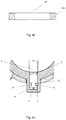
- Fig. 2 is a schematic sectional view of the throttle of the present device after assembly.
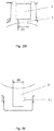
- Fig. 3A is a front view of the throttle housing of the present device.
- Fig. 3B is an enlarged schematic view of part A shown in Fig. 3A .
- Fig. 3C is an enlarged schematic view of part B shown in Fig. 3A .
- Figs. 1 is a schematic exploded view of the components of the throttle of the present device.
- Fig. 2 is a schematic sectional view of the throttle of the present device after assembly.
- Fig. 3A is a front view of the throttle housing of the present device.
- Fig. 3B is an enlarged schematic view of part A shown in Fig. 3A .
- Fig. 3C is an enlarged schematic view of part B shown in Fig. 3A .
- the throttle comprises: a throttle housing 1 for providing support and a protective function, and an electric machine 2 located inside the throttle housing 1, the electric machine 2 being used for supplying a torque; a torque transfer means 3 meshed with a gear on an output shaft of the electric machine 2, wherein in this embodiment, the torque transfer means may comprise an intermediate gear 31 meshed with the output gear of the electric machine 2 (the intermediate gear 31 being mounted on an intermediate shaft on the throttle housing 1), and a sector gear 32 meshed with the intermediate gear 31, with a return spring being mounted on the sector gear 32; a throttle shaft 4 connected in a fixed manner to the torque transfer means 3 (connected in a fixed manner to the sector gear 32), wherein an output torque of the electric machine 2 is transferred to the throttle shaft 4 via the torque transfer means 3, and the throttle shaft 4 passes through a throttle throat and is supported by being inserted into a first mounting hole 6 and a second mounting hole 7 in the throttle housing 1, wherein the first mounting hole 6 and the second mounting hole 7 are located in the throttle housing on two sides respectively of the throttle throat
- the first mounting hole 6 and second mounting hole 7 have hole inner diameters of the same size; as Figs. 3B and 3C show, the inner diameter d2 of the first mounting hole 6 is equal to the inner diameter d1 of the second mounting hole 7, and as Figs. 2 , 3A and 3C show, the first mounting hole 6 has a blind hole design. Regardless of whether the throttle housing 1 is of metal material or plastic material, the abovementioned blind hole design is suitable.
- a forming cutter may be used to form the first mounting hole 6 and second mounting hole 7 in a single operation from the side on which the second mounting hole 7 is located, thereby increasing the precision of hole positioning and lowering the requirements on equipment capability, as well as reducing the number of processing cutters and saving time and costs.
- a plastic housing only one mandrel is needed for core pulling, the precision of hole positioning can be increased, the mold scheme is simple, and the cost of injection molding is reduced.
- the first mounting hole 6 is a blind hole, sealing is better, the system leakage amount can be reduced effectively, no machining and subsequent press-fitting is needed, the number of components is small, and the cost is low.
- the electronic throttle also comprises a third mounting hole 8 which is located in the throttle housing 1 and used for supporting the throttle shaft 4, the third mounting hole 8 being located between the second mounting hole 7 and the torque transfer means 3 and being in communication with the second mounting hole 7; in general, the inner diameter of the third mounting hole 8 is greater than the inner diameter of the second mounting hole 7.
- a supporting bearing 9 which forms a clearance fit with the throttle shaft 4 and a sealing ring 10 mounted on the periphery of the throttle shaft 4; the sealing ring 10 may be located on either side of the supporting bearing 9.
- the supporting bearing 9 may be a sliding bearing, with an interference fit between an outer ring thereof and the third mounting hole 8.
- the sealing ring 10 is preferably located between the supporting bearing 9 and the second mounting hole 7.
- an interference fit is formed between an inner ring of the sealing ring 10 and the throttle shaft 4, and an interference fit is formed between an outer ring of the sealing ring 10 and the third mounting hole 8.
- the sealing ring 10 is similar to an annular structure; the cross-sectional shape thereof may be X-shaped, B-shaped, Y-shaped, O-shaped or rectangular, but in this embodiment is preferably X-shaped ( Fig. 4C ) ; this is because in this case, the inner ring and outer ring of the sealing ring will each form two protruding points, such that two sealing lips are formed between the sealing ring 10 and the throttle shaft 4, and between the sealing ring 10 and the third mounting hole 8, respectively; such an X-shaped structure is more stable, and not liable to experience twisting deformation which would impair the sealing effect.
- the sealing ring 10 is located outside the supporting bearing 9, and there is a gap 11 between the sealing ring 10 and the supporting bearing 9 in the axial direction of the supporting bearing 9.
- an oil/grease or molybdenum disulphide is provided between the first mounting hole 6 and the throttle shaft 4.
- the interior of the supporting bearing 9 no longer contains another seal.
- a first locating pin mounting groove 61 is formed on the throttle housing 1, and a second locating pin mounting groove 41 is formed on the throttle shaft 4 (the second locating pin mounting groove 41 may be a groove which runs all the way round the outer surface of the throttle shaft 4) ; a space between the first locating pin mounting groove 61 and the second locating pin mounting groove 41 forms a locating pin mounting hole 12.
- the electronic throttle also comprises a locating pin 11 mounted inside the locating pin mounting hole 12.
- the first locating pin mounting groove 61, second locating pin mounting groove 41, locating pin mounting hole 12 and locating pin 11 are all located inside the first mounting hole 6.
- At least one small boss structure 13 is formed at the bottom of the first mounting hole 6.
- the boss structure 13 is used to set an initial positioning face on the throttle housing 1, for performing initial positioning of the throttle shaft 4, and the first locating pin mounting groove 61 is set on the throttle housing 1, for determining a final stop position of the throttle shaft 4.
- the position tolerance thereof must be designed to be +/-0.3mm or less.
- an end face of the throttle shaft 4 located inside the first mounting hole 6 and a top surface of the boss structure 13 may be in contact with and press against each other, with a gap 14 being formed between an end face of the throttle shaft 4 located inside the first mounting hole 6 and the bottom of the first mounting hole 6.
- the function of the gap 14 is to prevent the throttle shaft 4 from becoming jammed in the throttle housing 1 due to the action of expansion upon heating and contraction upon cooling during operation of the throttle.
- the electronic throttle also comprises: an insert 15 mounted inside the throttle housing 1.
- an insert 15 mounted inside the throttle housing 1.
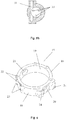
- Many schemes are possible for the structure of the insert 15; two preferred schemes are described in this embodiment: The first scheme is shown in Figs. 2 , 6 and 7 .
- the insert 15 is an annular three-dimensional structure formed and enclosed by a first flange face 16, a second flange face 17, an outer cylindrical face 18 and an inner cylindrical face 19, the inner cylindrical face 19 of the insert 15 forming the throat of the throttle.
- a front shaft hole 20 and a rear shaft hole 21, positioned opposite each other, are formed in the insert 15.
- One end of the throttle shaft 4 is inserted into the front shaft hole 20 and then mounted in the second mounting hole 7 and third mounting hole 8.
- the other end of the throttle shaft 4 is inserted into the rear shaft hole 21 and then mounted in the first mounting hole 6.
- Multiple axial holes 22 running in the axial direction of the insert 15 are formed on the first flange face 16 of the insert 15, each axial hole 22 being located between the outer cylindrical face 18 and the inner cylindrical face 19, and the interior of each axial hole 22 being filled with the material from which the throttle housing 1 is manufactured.
- Each of the axial holes 22 is surrounded by a flange 23, the flange 23 being a protruding structure located on the outer cylindrical face 18 of the insert 15.
- Two flanges 23 are distributed symmetrically on two sides of the front shaft hole 20, with a pin hole 24 being formed on each flange 23.
- the two pin holes 24 on the two flanges 23 distributed symmetrically on two sides of the front shaft hole 20 are distributed on two sides of the axis center of the throttle shaft 4.
- the protrusion height of the two flanges 23 on two sides of the front shaft hole 20 is greater than the protrusion height of the flanges 23 in other positions on the insert 15.
- Each of the flanges 23 extends from the first flange face 16 of the insert 15 to the second flange face 17.
- the interiors of the front shaft hole 20 and rear shaft hole 21 are partially filled with the material from which the throttle housing 1 is manufactured.
- the axial holes 22 penetrate to the second flange face 17 from the first flange face 16 of the insert 15.
- the insert 15 is an annular three-dimensional structure formed and enclosed by a first flange face 33, a second flange face 34, an inner cylindrical face 35 and an outer cylindrical face 36, the inner cylindrical face 35 of the insert 15 forming the throat of the throttle.
- a front shaft hole 37 and a rear shaft hole 38, positioned opposite each other, are formed in the insert 15.
- One end of the throttle shaft 4 is inserted into the front shaft hole 37 and then mounted in the second mounting hole 7 and third mounting hole 8.
- the other end of the throttle shaft 4 is inserted into the rear shaft hole 38 and then mounted in the first mounting hole 6.
- protruding structures 39 and the same number of recess structures 40 are formed on the first flange face 33 of the insert 15; any two adjacent protruding structures 39 are separated by one recess structure 40.
- Each of the protruding structures 39 has one side connected to the outer cylindrical face 36 of the insert 15.
- Provided on the outer cylindrical face 36 are at least two arcuate grooves 42 extending from the first flange face 33 to the second flange face 34, each of the arcuate grooves 42 sharing an edge with one of the recess structures 40.
- Two flanges 43 are distributed symmetrically on two sides of the front shaft hole 37 on the outer cylindrical face 36, with a pin hole 44 being formed on each flange 43, and the two pin holes 44 being distributed on two sides of the axis center of the throttle shaft 4.
- the interiors of the front shaft hole 37 and rear shaft hole 38 are partially filled with the material from which the throttle housing 1 is manufactured.
- the throttle also comprises an outer cover assembly 25 fitted to the housing 1, an electrical connector 26 for supplying power to the electric machine 2 and transmitting signals, a magnet 27 mounted on the torque transfer means 3, and a position sensor 28 mounted inside the outer cover assembly 25.
- a blank can be produced first by extrusion or diecasting, or by machining, then the insert is placed into a mold, and the throttle housing 1 containing the insert 15 is formed by injection molding.
- the plastic material of the throttle housing 1 partially fills the front shaft hole 20 and rear shaft hole 21 of the insert 15, and to achieve precise airflow control, the required airflow channel precision is ensured by a small amount of machining.
Landscapes
- Engineering & Computer Science (AREA)
- Chemical & Material Sciences (AREA)
- Combustion & Propulsion (AREA)
- Mechanical Engineering (AREA)
- General Engineering & Computer Science (AREA)
- Control Of Throttle Valves Provided In The Intake System Or In The Exhaust System (AREA)
Abstract
The present device relates to an electronic throttle, comprising:
a throttle housing (1) and, located inside the throttle housing (1) :
an electric machine (2);
a torque transfer means (3) meshed with a gear on an output shaft of the electric machine (2);
a throttle shaft (4) connected in a fixed manner to the torque transfer means (3), the throttle shaft (4) passing through a throttle throat, and being supported by being inserted into a first mounting hole (6) and a second mounting hole (7) in the throttle housing (1), wherein the first mounting hole (6) and the second mounting hole (7) are located in the throttle housing (1) on two sides of the throttle throat respectively, the second mounting hole (7) being located on that side which is closer to the torque transfer means (3);
a butterfly valve (5) which is mounted on the throttle shaft (4) and located inside the throttle throat;
wherein
the first mounting hole (6) and second mounting hole (7) have hole inner diameters of the same size, characterized in that the electronic throttle also comprises: an insert (15) mounted inside the throttle housing (1).
a throttle housing (1) and, located inside the throttle housing (1) :
an electric machine (2);
a torque transfer means (3) meshed with a gear on an output shaft of the electric machine (2);
a throttle shaft (4) connected in a fixed manner to the torque transfer means (3), the throttle shaft (4) passing through a throttle throat, and being supported by being inserted into a first mounting hole (6) and a second mounting hole (7) in the throttle housing (1), wherein the first mounting hole (6) and the second mounting hole (7) are located in the throttle housing (1) on two sides of the throttle throat respectively, the second mounting hole (7) being located on that side which is closer to the torque transfer means (3);
a butterfly valve (5) which is mounted on the throttle shaft (4) and located inside the throttle throat;
wherein
the first mounting hole (6) and second mounting hole (7) have hole inner diameters of the same size, characterized in that the electronic throttle also comprises: an insert (15) mounted inside the throttle housing (1).
Description
- The present device relates to a motor vehicle component product, in particular to an electronic throttle for use in a motor vehicle motive power assembly.
- A throttle device is generally provided in an internal combustion engine, arranged upstream of the air intake manifold and in communication with the air intake pipeline. It is used to control the flow rate of air supplied to the air intake manifold, and thereby control the flow rate of air entering the engine cylinders.
- Commonly used throttles on the market at present have the following structural features: 1) a throttle shaft thereof must always be supported by bearings (e.g. needle roller bearings) mounted in throttle mounting holes on two sides of the throat; 2) a sealing plug is mounted in one of the bearing mounting holes to achieve sealing; 3) locating is performed by mounting a C-shaped washer on the throttle shaft; 4) a seal is always contained inside a needle roller bearing or roller bearing mounted in a bearing mounting hole on one side of a gearbox, and one side of the gearbox inside the throttle is sealed by means of the seal; 5) the throat of the throttle contains no insert, or contains an insert but has a complex structure.
- A throttle having the structural features described above has the following drawbacks: 1) During machining, the precision requirements for the positions of the two bearing mounting holes are very high; high equipment processing precision is needed, the processing time is long, and the rejection rate is high. 2) A high-precision adjusting apparatus is needed to adjust axial gaps; costs are increased, adjustment is difficult, and the rejection rate is high. 3) Since the seal is integrated in the interior of the needle roller bearing or roller bearing, regions which are exposed outside the seal are very easily corroded by external media; in extreme cases, this results in the throttle being unable to regulate airflow normally. In order to enable the seal to be integrated in the needle roller or roller bearing and ensure the reliability of sealing and a smaller frictional torque, the structure of the seal will have a complex design, resulting in a high price and making manufacture difficult. Moreover, since single-point sealing is required, the inside surface of the bearing outer ring and the throttle shaft are required to be of very high quality in the case where the sealing pressure is not high. 4) A single-piece throttle valve body made of a metal material is heavy, involves a complex process, causes serious pollution, and has high production costs.
- The prior art documents
JP 2009 162085 A DE 10 2011 079742 A1CN 203 867 715 U andCN 204 003 113 U each refer to an electronic throttle device. - The object of the present device is to provide an electronic throttle, to solve the following problems which affect existing throttles: 1) component processing precision is low, while processing equipment requirements are high; 2) a precise instrument is needed to perform axial gap adjustment during axial positioning of the throttle shaft; 3) the sealing structure is complex, components outside the seal may cause corrosion, and manufacturing is difficult; 4) the manufacturing cost is high, and pollution is serious.
- The electronic throttle provided by the present device comprises :
athrottle housing 1 and, located inside the throttle housing 1:
anelectric machine 2; a torque transfer means 3 meshed with a gear on an output shaft of theelectric machine 2; athrottle shaft 4 connected in a fixed manner to the torque transfer means 3, thethrottle shaft 4 passing through a throttle throat, and being supported by being inserted into afirst mounting hole 6 and asecond mounting hole 7 in thethrottle housing 1, wherein thefirst mounting hole 6 and thesecond mounting hole 7 are located in thethrottle housing 1 on two sides of the throttle throat respectively, thesecond mounting hole 7 being located on that side which is closer to the torque transfer means 3; abutterfly valve 5 which is mounted on thethrottle shaft 4 and located inside the throttle throat; thefirst mounting hole 6 and second mountinghole 7 having hole inner diameters of the same size. - Furthermore, the electronic throttle also comprises: an
insert 15 mounted inside thethrottle housing 1. - Furthermore, the
insert 15 is an annular three-dimensional structure formed and enclosed by afirst flange face 16, asecond flange face 17, an outercylindrical face 18 and an innercylindrical face 19, the innercylindrical face 19 of theinsert 15 forming the throat of the throttle; afront shaft hole 20 and arear shaft hole 21, positioned opposite each other, are formed in theinsert 15; one end of thethrottle shaft 4 is inserted into thefront shaft hole 20 and then mounted in thesecond mounting hole 7 andthird mounting hole 8; the other end of thethrottle shaft 4 is inserted into therear shaft hole 21 and then mounted in thefirst mounting hole 6; multipleaxial holes 22 running in the axial direction of theinsert 15 are formed on thefirst flange face 16 of theinsert 15, eachaxial hole 22 being located between the outercylindrical face 18 and the innercylindrical face 19, and the interior of eachaxial hole 22 being filled with the material from which thethrottle housing 1 is manufactured. Each of theaxial holes 22 is surrounded by aflange 23, theflange 23 being a protruding structure located on the outercylindrical face 18 of theinsert 15. Twoflanges 23 are distributed symmetrically on two sides of thefront shaft hole 20, with apin hole 24 being formed on eachflange 23. The twopin holes 24 on the twoflanges 23 distributed symmetrically on two sides of thefront shaft hole 20 are distributed on two sides of the axis center of thethrottle shaft 4. The protrusion height of the twoflanges 23 on two sides of thefront shaft hole 20 is greater than the protrusion height of theflanges 23 in other positions on theinsert 15. Each of theflanges 23 extends from thefirst flange face 16 of theinsert 15 to thesecond flange face 17. The interiors of thefront shaft hole 20 andrear shaft hole 21 are partially filled with the material from which thethrottle housing 1 is manufactured. Theaxial holes 22 penetrate to thesecond flange face 17 from thefirst flange face 16 of theinsert 15. - Optionally, the
insert 15 is an annular three-dimensional structure formed and enclosed by afirst flange face 33, asecond flange face 34, an innercylindrical face 35 and an outercylindrical face 36, the innercylindrical face 35 of theinsert 15 forming the throat of the throttle; afront shaft hole 37 and arear shaft hole 38, positioned opposite each other, are formed in theinsert 15; one end of thethrottle shaft 4 is inserted into thefront shaft hole 37 and then mounted in thesecond mounting hole 7 andthird mounting hole 8; the other end of thethrottle shaft 4 is inserted into therear shaft hole 38 and then mounted in thefirst mounting hole 6;multiple protruding structures 39 and the same number ofrecess structures 40 are formed on thefirst flange face 33 of theinsert 15; any twoadjacent protruding structures 39 are separated by onerecess structure 40. Each of theprotruding structures 39 has one side connected to the outercylindrical face 36 of theinsert 15. Provided on the outercylindrical face 36 are at least twoarcuate grooves 42 extending from thefirst flange face 33 to thesecond flange face 34, each of thearcuate grooves 42 sharing an edge with one of therecess structures 40. Twoflanges 43 are distributed symmetrically on two sides of thefront shaft hole 37 on the outercylindrical face 36, with apin hole 44 being formed on eachflange 43, and the twopin holes 44 being distributed on two sides of the axis center of thethrottle shaft 4. The interiors of thefront shaft hole 37 andrear shaft hole 38 are partially filled with the material from which thethrottle housing 1 is manufactured. - Furthermore, an
outer cover assembly 25 fitted to thehousing 1, anelectrical connector 26 for supplying power to theelectric machine 2 and transmitting signals, amagnet 27 mounted on the torque transfer means 3, and aposition sensor 28 mounted inside theouter cover assembly 25. - Compared with the prior art, the use of the electronic throttle provided by the present device has the advantages of a simple structure, high processing precision, good sealing, low manufacturing costs, and a simple assembly process flow.
- The accompanying drawings, which form part of the present application, are used to furnish further understanding of the present device. The schematic embodiments of the present device and the explanations thereof are intended to explain the present device, without constituting an inappropriate limitation thereof. Drawings:
- Fig. 1
- is a schematic exploded view of the components of the throttle of the present device.
- Fig. 2
- is a schematic sectional view of the throttle of the present device after assembly.
- Fig. 3A
- is a front view of the throttle housing of the present device.
- Fig. 3B
- is an enlarged schematic view of part A shown in
Fig. 3A . - Fig. 3C
- is an enlarged schematic view of part B shown in
Fig. 3A . - Fig. 4A
- is an enlarged schematic view of part C shown in
Fig. 2 . - Fig. 4B
- is a schematic perspective view of the sealing ring shown in
Fig. 4A . - Fig. 4C
- is a sectional front view of the sealing ring shown in
Fig. 4B . - Fig. 5A
- is an enlarged schematic view of part D shown in
Fig. 2 . - Fig. 5B
- is a schematic top view of the bottom of the blind hole shown in
Fig. 5A (in the case where no throttle shaft is mounted). - Fig. 6
- is a schematic perspective view of one embodiment of the insert.
- Fig. 7
- is a front view of the insert shown in
Fig. 6 . - Fig. 8
- is a schematic perspective view of another embodiment of the insert.
- Fig. 9
- is a front view of the insert shown in
Fig. 8 . - The electronic throttle of the present device is described below by way of embodiments with reference to the accompanying drawings.
-
Fig. 1 is a schematic exploded view of the components of the throttle of the present device.Fig. 2 is a schematic sectional view of the throttle of the present device after assembly.Fig. 3A is a front view of the throttle housing of the present device.Fig. 3B is an enlarged schematic view of part A shown inFig. 3A .Fig. 3C is an enlarged schematic view of part B shown inFig. 3A . AsFigs. 1 and2 show, the throttle comprises: a throttle housing 1 for providing support and a protective function, and an electric machine 2 located inside the throttle housing 1, the electric machine 2 being used for supplying a torque; a torque transfer means 3 meshed with a gear on an output shaft of the electric machine 2, wherein in this embodiment, the torque transfer means may comprise an intermediate gear 31 meshed with the output gear of the electric machine 2 (the intermediate gear 31 being mounted on an intermediate shaft on the throttle housing 1), and a sector gear 32 meshed with the intermediate gear 31, with a return spring being mounted on the sector gear 32; a throttle shaft 4 connected in a fixed manner to the torque transfer means 3 (connected in a fixed manner to the sector gear 32), wherein an output torque of the electric machine 2 is transferred to the throttle shaft 4 via the torque transfer means 3, and the throttle shaft 4 passes through a throttle throat and is supported by being inserted into a first mounting hole 6 and a second mounting hole 7 in the throttle housing 1, wherein the first mounting hole 6 and the second mounting hole 7 are located in the throttle housing on two sides respectively of the throttle throat, the second mounting hole 7 being located on that side which is closer to the torque transfer means 3; and a butterfly valve 5 which is mounted on the throttle shaft 4 and located inside the throttle throat, the butterfly valve 5 being capable of rotating together with the throttle shaft 4, so as to control the degree of opening of the throttle throat. - Preferably, to reduce the machining difficulty, the rejection rate and costs, in this embodiment the first mounting
hole 6 and second mountinghole 7 have hole inner diameters of the same size; asFigs. 3B and 3C show, the inner diameter d2 of the first mountinghole 6 is equal to the inner diameter d1 of thesecond mounting hole 7, and asFigs. 2 ,3A and3C show, the first mountinghole 6 has a blind hole design. Regardless of whether thethrottle housing 1 is of metal material or plastic material, the abovementioned blind hole design is suitable. In the case of a metal housing, a forming cutter may be used to form the first mountinghole 6 and second mountinghole 7 in a single operation from the side on which thesecond mounting hole 7 is located, thereby increasing the precision of hole positioning and lowering the requirements on equipment capability, as well as reducing the number of processing cutters and saving time and costs. In the case of a plastic housing, only one mandrel is needed for core pulling, the precision of hole positioning can be increased, the mold scheme is simple, and the cost of injection molding is reduced. Moreover, when the first mountinghole 6 is a blind hole, sealing is better, the system leakage amount can be reduced effectively, no machining and subsequent press-fitting is needed, the number of components is small, and the cost is low. - Preferably, as
Figs. 2 ,3A and4A show, the electronic throttle also comprises athird mounting hole 8 which is located in thethrottle housing 1 and used for supporting thethrottle shaft 4, the third mountinghole 8 being located between thesecond mounting hole 7 and the torque transfer means 3 and being in communication with thesecond mounting hole 7; in general, the inner diameter of the third mountinghole 8 is greater than the inner diameter of thesecond mounting hole 7. - Preferably, as
Fig. 4A shows, inside the third mountinghole 8 are mounted a supportingbearing 9 which forms a clearance fit with thethrottle shaft 4 and a sealingring 10 mounted on the periphery of thethrottle shaft 4; the sealingring 10 may be located on either side of the supportingbearing 9. The supportingbearing 9 may be a sliding bearing, with an interference fit between an outer ring thereof and the third mountinghole 8. In this embodiment, the sealingring 10 is preferably located between the supportingbearing 9 and thesecond mounting hole 7. - Preferably, an interference fit is formed between an inner ring of the sealing
ring 10 and thethrottle shaft 4, and an interference fit is formed between an outer ring of the sealingring 10 and the third mountinghole 8. - Preferably, as
Figs. 4B and4C show, the sealingring 10 is similar to an annular structure; the cross-sectional shape thereof may be X-shaped, B-shaped, Y-shaped, O-shaped or rectangular, but in this embodiment is preferably X-shaped (Fig. 4C ) ; this is because in this case, the inner ring and outer ring of the sealing ring will each form two protruding points, such that two sealing lips are formed between the sealingring 10 and thethrottle shaft 4, and between the sealingring 10 and the third mountinghole 8, respectively; such an X-shaped structure is more stable, and not liable to experience twisting deformation which would impair the sealing effect. - Preferably, as
Fig. 4A shows, the sealingring 10 is located outside the supportingbearing 9, and there is agap 11 between the sealingring 10 and the supportingbearing 9 in the axial direction of the supportingbearing 9. - Preferably, to achieve the object of reducing friction, an oil/grease or molybdenum disulphide is provided between the first mounting
hole 6 and thethrottle shaft 4. - Preferably, to simplify components, and reduce the difficulty of design and assembly, the interior of the supporting
bearing 9 no longer contains another seal. - Preferably, as
Figs. 5A and5B show, a first locatingpin mounting groove 61 is formed on thethrottle housing 1, and a second locatingpin mounting groove 41 is formed on the throttle shaft 4 (the second locatingpin mounting groove 41 may be a groove which runs all the way round the outer surface of the throttle shaft 4) ; a space between the first locatingpin mounting groove 61 and the second locatingpin mounting groove 41 forms a locatingpin mounting hole 12. - Preferably, the electronic throttle also comprises a locating
pin 11 mounted inside the locatingpin mounting hole 12. - Preferably, the first locating
pin mounting groove 61, second locatingpin mounting groove 41, locatingpin mounting hole 12 and locatingpin 11 are all located inside the first mountinghole 6. - Preferably, at least one
small boss structure 13 is formed at the bottom of the first mountinghole 6. (In this embodiment, there are threesuch boss structures 13.) In terms of function, theboss structure 13 is used to set an initial positioning face on thethrottle housing 1, for performing initial positioning of thethrottle shaft 4, and the first locatingpin mounting groove 61 is set on thethrottle housing 1, for determining a final stop position of thethrottle shaft 4. There is a designed positional relationship between the positioning face formed by theboss structure 13 and the first locatingpin mounting groove 61; the position tolerance thereof must be designed to be +/-0.3mm or less. Moreover, an end face of thethrottle shaft 4 located inside the first mountinghole 6 and a top surface of theboss structure 13 may be in contact with and press against each other, with agap 14 being formed between an end face of thethrottle shaft 4 located inside the first mountinghole 6 and the bottom of the first mountinghole 6. The function of thegap 14 is to prevent thethrottle shaft 4 from becoming jammed in thethrottle housing 1 due to the action of expansion upon heating and contraction upon cooling during operation of the throttle. - Preferably, the electronic throttle also comprises: an
insert 15 mounted inside thethrottle housing 1. Many schemes are possible for the structure of theinsert 15; two preferred schemes are described in this embodiment:
The first scheme is shown inFigs. 2 ,6 and7 . Theinsert 15 is an annular three-dimensional structure formed and enclosed by afirst flange face 16, asecond flange face 17, an outercylindrical face 18 and an innercylindrical face 19, the innercylindrical face 19 of theinsert 15 forming the throat of the throttle. Afront shaft hole 20 and arear shaft hole 21, positioned opposite each other, are formed in theinsert 15. One end of thethrottle shaft 4 is inserted into thefront shaft hole 20 and then mounted in thesecond mounting hole 7 and third mountinghole 8. The other end of thethrottle shaft 4 is inserted into therear shaft hole 21 and then mounted in the first mountinghole 6. Multipleaxial holes 22 running in the axial direction of theinsert 15 are formed on thefirst flange face 16 of theinsert 15, eachaxial hole 22 being located between the outercylindrical face 18 and the innercylindrical face 19, and the interior of eachaxial hole 22 being filled with the material from which thethrottle housing 1 is manufactured. Each of theaxial holes 22 is surrounded by aflange 23, theflange 23 being a protruding structure located on the outercylindrical face 18 of theinsert 15. Twoflanges 23 are distributed symmetrically on two sides of thefront shaft hole 20, with apin hole 24 being formed on eachflange 23. The two pin holes 24 on the twoflanges 23 distributed symmetrically on two sides of thefront shaft hole 20 are distributed on two sides of the axis center of thethrottle shaft 4. The protrusion height of the twoflanges 23 on two sides of thefront shaft hole 20 is greater than the protrusion height of theflanges 23 in other positions on theinsert 15. Each of theflanges 23 extends from thefirst flange face 16 of theinsert 15 to thesecond flange face 17. The interiors of thefront shaft hole 20 andrear shaft hole 21 are partially filled with the material from which thethrottle housing 1 is manufactured. Theaxial holes 22 penetrate to thesecond flange face 17 from thefirst flange face 16 of theinsert 15. - A drawing showing another structure of the
insert 15 combined with thethrottle housing 1 is not shown in this patent, but the specific structure thereof is shown inFigs. 8 and9 . Theinsert 15 is an annular three-dimensional structure formed and enclosed by afirst flange face 33, asecond flange face 34, an innercylindrical face 35 and an outercylindrical face 36, the innercylindrical face 35 of theinsert 15 forming the throat of the throttle. Afront shaft hole 37 and arear shaft hole 38, positioned opposite each other, are formed in theinsert 15. One end of thethrottle shaft 4 is inserted into thefront shaft hole 37 and then mounted in thesecond mounting hole 7 and third mountinghole 8. The other end of thethrottle shaft 4 is inserted into therear shaft hole 38 and then mounted in the first mountinghole 6. Multiple protrudingstructures 39 and the same number ofrecess structures 40 are formed on thefirst flange face 33 of theinsert 15; any two adjacent protrudingstructures 39 are separated by onerecess structure 40. Each of the protrudingstructures 39 has one side connected to the outercylindrical face 36 of theinsert 15. Provided on the outercylindrical face 36 are at least twoarcuate grooves 42 extending from thefirst flange face 33 to thesecond flange face 34, each of thearcuate grooves 42 sharing an edge with one of therecess structures 40. Twoflanges 43 are distributed symmetrically on two sides of thefront shaft hole 37 on the outercylindrical face 36, with apin hole 44 being formed on eachflange 43, and the twopin holes 44 being distributed on two sides of the axis center of thethrottle shaft 4. The interiors of thefront shaft hole 37 andrear shaft hole 38 are partially filled with the material from which thethrottle housing 1 is manufactured. - Preferably, the throttle also comprises an
outer cover assembly 25 fitted to thehousing 1, anelectrical connector 26 for supplying power to theelectric machine 2 and transmitting signals, amagnet 27 mounted on the torque transfer means 3, and aposition sensor 28 mounted inside theouter cover assembly 25. - During actual production, in the case of the
insert 15 serving as an airflow delivery channel, a blank can be produced first by extrusion or diecasting, or by machining, then the insert is placed into a mold, and thethrottle housing 1 containing theinsert 15 is formed by injection molding. During the injection molding, the plastic material of thethrottle housing 1 partially fills thefront shaft hole 20 andrear shaft hole 21 of theinsert 15, and to achieve precise airflow control, the required airflow channel precision is ensured by a small amount of machining.
Claims (15)
- An electronic throttle, comprising:a throttle housing (1) and, located inside the throttle housing (1):an electric machine (2);a torque transfer means (3) meshed with a gear on an output shaft of the electric machine (2);a throttle shaft (4) connected in a fixed manner to the torque transfer means (3), the throttle shaft (4) passing through a throttle throat, and being supported by being inserted into a first mounting hole (6) and a second mounting hole (7) in the throttle housing (1), wherein the first mounting hole (6) and the second mounting hole (7) are located in the throttle housing (1) on two sides of the throttle throat respectively, the second mounting hole (7) being located on that side which is closer to the torque transfer means (3);a butterfly valve (5) which is mounted on the throttle shaft (4) and located inside the throttle throat;whereinthe first mounting hole (6) and second mounting hole (7) have hole inner diameters of the same size, characterized in that the electronic throttle also comprises: an insert (15) mounted inside the throttle housing (1).
- The electronic throttle as claimed in claim 1, characterized in that the insert (15) is an annular three-dimensional structure formed and enclosed by a first flange face (16), a second flange face (17), an outer cylindrical face (18) and an inner cylindrical face (19), the inner cylindrical face (19) of the insert (15) forming the throat of the throttle; a front shaft hole (20) and a rear shaft hole (21), positioned opposite each other, are formed in the insert (15) ; one end of the throttle shaft (4) is inserted into the front shaft hole (20) and then mounted in the second mounting hole (7) and third mounting hole (8); the other end of the throttle shaft (4) is inserted into the rear shaft hole (21) and then mounted in the first mounting hole (6); multiple axial holes (22) running in the axial direction of the insert (15) are formed on the first flange face (16) of the insert (15), each axial hole (22) being located between the outer cylindrical face (18) and the inner cylindrical face (19), and the interior of each axial hole (22) being filled with the material from which the throttle housing (1) is manufactured.
- The electronic throttle as claimed in claim 2, characterized in that each of the axial holes (22) is surrounded by a flange (23), the flange (23) being a protruding structure located on the outer cylindrical face (18) of the insert (15).
- The electronic throttle as claimed in claim 3, characterized in that two flanges (23) are distributed symmetrically on two sides of the front shaft hole (20), with a pin hole (24) being formed on each flange (23).
- The electronic throttle as claimed in claim 4, characterized in that the two pin holes (24) on the two flanges (23) distributed symmetrically on two sides of the front shaft hole (20) are distributed on two sides of the axis center of the throttle shaft (4).
- The electronic throttle as claimed in claim 4, characterized in that the protrusion height of the two flanges (23) on two sides of the front shaft hole (20) is greater than the protrusion height of the flanges (23) in other positions on the insert (15).
- The electronic throttle as claimed in claim 3, characterized in that each of the flanges (23) extends from the first flange face (16) of the insert (15) to the second flange face (17) .
- The electronic throttle as claimed in claim 2, characterized in that the interiors of the front shaft hole (20) and rear shaft hole (21) are partially filled with the material from which the throttle housing (1) is manufactured.
- The electronic throttle as claimed in claim 2, characterized in that the axial holes (22) penetrate to the second flange face (17) from the first flange face (16) of the insert (15) .
- The electronic throttle as claimed in claim 1, characterized in that the insert (15) is an annular three-dimensional structure formed and enclosed by a first flange face (33), a second flange face (34), an inner cylindrical face (35) and an outer cylindrical face (36), the inner cylindrical face (35) of the insert (15) forming the throat of the throttle; a front shaft hole (37) and a rear shaft hole (38), positioned opposite each other, are formed in the insert (15) ; one end of the throttle shaft (4) is inserted into the front shaft hole (37) and then mounted in the second mounting hole (7) and third mounting hole (8); the other end of the throttle shaft (4) is inserted into the rear shaft hole (38) and then mounted in the first mounting hole (6); multiple protruding structures (39) and the same number of recess structures (40) are formed on the first flange face (33) of the insert (15) ; any two adjacent protruding structures (39) are separated by one recess structure (40).
- The electronic throttle as claimed in claim 10, characterized in that each of the protruding structures (39) has one side connected to the outer cylindrical face (36) of the insert (15).
- The electronic throttle as claimed in claim 10, characterized in that provided on the outer cylindrical face (36) are at least two arcuate grooves (42) extending from the first flange face (33) to the second flange face (34), each of the arcuate grooves (42) sharing an edge with one of the recess structures (40).
- The electronic throttle as claimed in claim 10, characterized in that two flanges (43) are distributed symmetrically on two sides of the front shaft hole (37) on the outer cylindrical face (36), with a pin hole (44) being formed on each flange (43), and the two pin holes (44) being distributed on two sides of the axis center of the throttle shaft (4).
- The electronic throttle as claimed in claim 10, characterized in that the interiors of the front shaft hole (37) and rear shaft hole (38) are partially filled with the material from which the throttle housing (1) is manufactured.
- The electronic throttle as claimed in claim 1, characterized by also comprising an outer cover assembly (25) fitted to the housing (1), an electrical connector (26) for supplying power to the electric machine (2) and transmitting signals, a magnet (27) mounted on the torque transfer means (3), and a position sensor (28) mounted inside the outer cover assembly (25).
Applications Claiming Priority (3)
| Application Number | Priority Date | Filing Date | Title |
|---|---|---|---|
| CN201520926271.XU CN205225467U (en) | 2015-11-19 | 2015-11-19 | Electronic air throttle |
| PCT/EP2016/077986 WO2017085179A1 (en) | 2015-11-19 | 2016-11-17 | Electronic throttle |
| EP16798466.5A EP3377747B1 (en) | 2015-11-19 | 2016-11-17 | Electronic throttle |
Related Parent Applications (2)
| Application Number | Title | Priority Date | Filing Date |
|---|---|---|---|
| EP16798466.5A Division EP3377747B1 (en) | 2015-11-19 | 2016-11-17 | Electronic throttle |
| EP16798466.5A Division-Into EP3377747B1 (en) | 2015-11-19 | 2016-11-17 | Electronic throttle |
Publications (1)
| Publication Number | Publication Date |
|---|---|
| EP3480444A1 true EP3480444A1 (en) | 2019-05-08 |
Family
ID=55900538
Family Applications (2)
| Application Number | Title | Priority Date | Filing Date |
|---|---|---|---|
| EP18206200.0A Withdrawn EP3480444A1 (en) | 2015-11-19 | 2016-11-17 | Electronic throttle |
| EP16798466.5A Active EP3377747B1 (en) | 2015-11-19 | 2016-11-17 | Electronic throttle |
Family Applications After (1)
| Application Number | Title | Priority Date | Filing Date |
|---|---|---|---|
| EP16798466.5A Active EP3377747B1 (en) | 2015-11-19 | 2016-11-17 | Electronic throttle |
Country Status (4)
| Country | Link |
|---|---|
| US (1) | US20180266335A1 (en) |
| EP (2) | EP3480444A1 (en) |
| CN (1) | CN205225467U (en) |
| WO (1) | WO2017085179A1 (en) |
Families Citing this family (4)
| Publication number | Priority date | Publication date | Assignee | Title |
|---|---|---|---|---|
| MX2012011155A (en) | 2010-03-29 | 2012-12-05 | Abraxis Bioscience Llc | Methods of enhancing drug delivery and effectiveness of therapeutic agents. |
| KR101970890B1 (en) * | 2017-10-12 | 2019-04-19 | 주식회사 현대케피코 | Assembly structure of electronic throttle valve device |
| USD868838S1 (en) * | 2018-01-01 | 2019-12-03 | Huayi Mechanical And Electrical Co., Ltd. | Electronic fuel injection (EFI) throttle valve |
| CN114278442A (en) * | 2021-12-27 | 2022-04-05 | 重庆渝辉机械有限公司 | Stable Diesel Electronic Throttle |
Citations (10)
| Publication number | Priority date | Publication date | Assignee | Title |
|---|---|---|---|---|
| JPH0318632A (en) * | 1989-06-14 | 1991-01-28 | Nippon Carbureter Co Ltd | Intake air quantity control device for engine |
| JPH10339178A (en) * | 1997-06-09 | 1998-12-22 | Aisan Ind Co Ltd | Throttle body |
| EP1083317A2 (en) * | 1999-09-08 | 2001-03-14 | Siemens Canada limited | Throttle body insert for intake manifold |
| EP1227228A2 (en) * | 2001-01-29 | 2002-07-31 | Denso Corporation | Throttle body with insert-molded member |
| DE102005041910A1 (en) * | 2005-09-03 | 2007-03-08 | GM Global Technology Operations, Inc., Detroit | Throttle body-intake manifold unit for e.g. passenger car, has throttle body unit partially inserted into manifold and sprayed with plastic e.g. polyamide, such that complete positive-fit connection is formed between body unit and manifold |
| JP2009162085A (en) | 2007-12-28 | 2009-07-23 | Denso Corp | Throttle device for a supercharged internal combustion engine |
| DE102011079742A1 (en) | 2011-07-25 | 2013-01-31 | Schaeffler Technologies AG & Co. KG | Control unit for exhaust gas recirculation in internal combustion engines, has throttle valve housing with gas channel, and throttle valve for regulating gas passing through gas channel |
| CN203867715U (en) | 2014-06-04 | 2014-10-08 | 四川田奥环保科技有限公司 | Electronic throttle valve installed on engine intake manifold |
| CN204003113U (en) | 2014-07-16 | 2014-12-10 | 重庆渝辉机械有限公司 | Electronic throttle of engine |
| EP2881564A1 (en) * | 2013-12-04 | 2015-06-10 | Magneti Marelli S.p.A. | Throttle valve for an internal combustion engine provided with a metal valve seat overmoulded inside a valve body made of a plastic material |
Family Cites Families (10)
| Publication number | Priority date | Publication date | Assignee | Title |
|---|---|---|---|---|
| DE4229587A1 (en) * | 1992-09-04 | 1994-03-10 | Hella Kg Hueck & Co | Air supply control for IC engine intake - has housing accommodating throttle with shaft in roller bearings held in through holes |
| JPH09170459A (en) * | 1997-01-20 | 1997-06-30 | Aisan Ind Co Ltd | Butterfly valve device |
| DE19854595A1 (en) * | 1998-11-26 | 2000-06-08 | Mannesmann Vdo Ag | Throttle valve neck |
| DE10138931A1 (en) * | 2001-08-08 | 2003-03-06 | Bosch Gmbh Robert | Throttle device housing with flexible compensating elements for internal combustion engines |
| JP2005090419A (en) * | 2003-09-19 | 2005-04-07 | Denso Corp | Throttle device for internal combustion engine |
| CN2823572Y (en) * | 2005-09-13 | 2006-10-04 | 上海奥众汽车部件制造有限公司 | Electric spraying gas saving valve for automobile |
| US8635986B2 (en) * | 2009-10-26 | 2014-01-28 | Aisan Kogyo Kabushiki Kaisha | Rotation angle sensors |
| JP5287887B2 (en) * | 2011-01-28 | 2013-09-11 | 株式会社デンソー | Intake device for internal combustion engine |
| JP5987877B2 (en) * | 2013-10-04 | 2016-09-07 | 株式会社デンソー | Electronic throttle |
| CN204704016U (en) * | 2015-06-08 | 2015-10-14 | 福建福鼎京科化油器有限公司 | A kind of EFI throttle-valve body of step motor control |
-
2015
- 2015-11-19 CN CN201520926271.XU patent/CN205225467U/en not_active Expired - Lifetime
-
2016
- 2016-11-17 EP EP18206200.0A patent/EP3480444A1/en not_active Withdrawn
- 2016-11-17 WO PCT/EP2016/077986 patent/WO2017085179A1/en not_active Ceased
- 2016-11-17 EP EP16798466.5A patent/EP3377747B1/en active Active
-
2018
- 2018-05-17 US US15/982,702 patent/US20180266335A1/en not_active Abandoned
Patent Citations (10)
| Publication number | Priority date | Publication date | Assignee | Title |
|---|---|---|---|---|
| JPH0318632A (en) * | 1989-06-14 | 1991-01-28 | Nippon Carbureter Co Ltd | Intake air quantity control device for engine |
| JPH10339178A (en) * | 1997-06-09 | 1998-12-22 | Aisan Ind Co Ltd | Throttle body |
| EP1083317A2 (en) * | 1999-09-08 | 2001-03-14 | Siemens Canada limited | Throttle body insert for intake manifold |
| EP1227228A2 (en) * | 2001-01-29 | 2002-07-31 | Denso Corporation | Throttle body with insert-molded member |
| DE102005041910A1 (en) * | 2005-09-03 | 2007-03-08 | GM Global Technology Operations, Inc., Detroit | Throttle body-intake manifold unit for e.g. passenger car, has throttle body unit partially inserted into manifold and sprayed with plastic e.g. polyamide, such that complete positive-fit connection is formed between body unit and manifold |
| JP2009162085A (en) | 2007-12-28 | 2009-07-23 | Denso Corp | Throttle device for a supercharged internal combustion engine |
| DE102011079742A1 (en) | 2011-07-25 | 2013-01-31 | Schaeffler Technologies AG & Co. KG | Control unit for exhaust gas recirculation in internal combustion engines, has throttle valve housing with gas channel, and throttle valve for regulating gas passing through gas channel |
| EP2881564A1 (en) * | 2013-12-04 | 2015-06-10 | Magneti Marelli S.p.A. | Throttle valve for an internal combustion engine provided with a metal valve seat overmoulded inside a valve body made of a plastic material |
| CN203867715U (en) | 2014-06-04 | 2014-10-08 | 四川田奥环保科技有限公司 | Electronic throttle valve installed on engine intake manifold |
| CN204003113U (en) | 2014-07-16 | 2014-12-10 | 重庆渝辉机械有限公司 | Electronic throttle of engine |
Also Published As
| Publication number | Publication date |
|---|---|
| CN205225467U (en) | 2016-05-11 |
| EP3377747A1 (en) | 2018-09-26 |
| EP3377747B1 (en) | 2020-01-15 |
| US20180266335A1 (en) | 2018-09-20 |
| WO2017085179A1 (en) | 2017-05-26 |
Similar Documents
| Publication | Publication Date | Title |
|---|---|---|
| EP3377747B1 (en) | Electronic throttle | |
| EP1947312B1 (en) | Butterfly valve device | |
| US9188159B2 (en) | Half thrust bearing and bearing device | |
| EP0947681A2 (en) | Clamshell throttle valve assembly | |
| CN218294522U (en) | Valve device | |
| WO2012014069A1 (en) | Roller bearing with seal integral with cage and camshaft apparatus having such a roller bearing | |
| JP2013072402A (en) | Variable capacity-type exhaust turbocharger equipped with variable nozzle mechanism | |
| US20170342914A1 (en) | Valve device | |
| DE102020121523A1 (en) | Throttle valve device | |
| US20100050984A1 (en) | Throttle device | |
| CN205101123U (en) | Air throttle with novel seal structure | |
| CN205605777U (en) | Spacing bearing seat of axial | |
| US8696214B2 (en) | Drawn bushing, particularly in form of a raceway bushing for an automatic transmission | |
| CN204692518U (en) | Automobile integrated component worm bearing | |
| CN204692336U (en) | Automobile EPS special self lubricating centre regulating worm component bearing | |
| CN110541930A (en) | Fluid passage structure and device having same | |
| US20210071743A1 (en) | Ball-screw nut with over-molded shell | |
| CN222254150U (en) | A flow control valve with a new axial positioning structure | |
| CN107883003B (en) | Electric valve for regulating fluid flow | |
| CN106762162A (en) | The axial gap method of adjustment of air throttle and throttle plate pin with axial positioning structure | |
| CN221683562U (en) | Transmission structure and electric drive system | |
| JP2005321026A (en) | Lubricating structure of rotor device and manufacturing method of lubricating structure of rotor device | |
| CN114857840B (en) | Air door device | |
| CN218022529U (en) | Continuous type blows embedment all-in-one forming die device | |
| US11174799B2 (en) | Integrated VDA housing with anti-rotation feature |
Legal Events
| Date | Code | Title | Description |
|---|---|---|---|
| PUAI | Public reference made under article 153(3) epc to a published international application that has entered the european phase |
Free format text: ORIGINAL CODE: 0009012 |
|
| AC | Divisional application: reference to earlier application |
Ref document number: 3377747 Country of ref document: EP Kind code of ref document: P |
|
| AK | Designated contracting states |
Kind code of ref document: A1 Designated state(s): AL AT BE BG CH CY CZ DE DK EE ES FI FR GB GR HR HU IE IS IT LI LT LU LV MC MK MT NL NO PL PT RO RS SE SI SK SM TR |
|
| STAA | Information on the status of an ep patent application or granted ep patent |
Free format text: STATUS: THE APPLICATION HAS BEEN WITHDRAWN |
|
| 18W | Application withdrawn |
Effective date: 20190820 |