EP3480370A1 - Hybrid load bucket assembly - Google Patents
Hybrid load bucket assembly Download PDFInfo
- Publication number
- EP3480370A1 EP3480370A1 EP18204521.1A EP18204521A EP3480370A1 EP 3480370 A1 EP3480370 A1 EP 3480370A1 EP 18204521 A EP18204521 A EP 18204521A EP 3480370 A1 EP3480370 A1 EP 3480370A1
- Authority
- EP
- European Patent Office
- Prior art keywords
- bucket
- shell
- frame
- struts
- assembly
- Prior art date
- Legal status (The legal status is an assumption and is not a legal conclusion. Google has not performed a legal analysis and makes no representation as to the accuracy of the status listed.)
- Granted
Links
Images






Classifications
-
- E—FIXED CONSTRUCTIONS
- E02—HYDRAULIC ENGINEERING; FOUNDATIONS; SOIL SHIFTING
- E02F—DREDGING; SOIL-SHIFTING
- E02F3/00—Dredgers; Soil-shifting machines
- E02F3/04—Dredgers; Soil-shifting machines mechanically-driven
- E02F3/28—Dredgers; Soil-shifting machines mechanically-driven with digging tools mounted on a dipper- or bucket-arm, i.e. there is either one arm or a pair of arms, e.g. dippers, buckets
- E02F3/36—Component parts
- E02F3/40—Dippers; Buckets ; Grab devices, e.g. manufacturing processes for buckets, form, geometry or material of buckets
-
- E—FIXED CONSTRUCTIONS
- E02—HYDRAULIC ENGINEERING; FOUNDATIONS; SOIL SHIFTING
- E02F—DREDGING; SOIL-SHIFTING
- E02F3/00—Dredgers; Soil-shifting machines
- E02F3/04—Dredgers; Soil-shifting machines mechanically-driven
- E02F3/28—Dredgers; Soil-shifting machines mechanically-driven with digging tools mounted on a dipper- or bucket-arm, i.e. there is either one arm or a pair of arms, e.g. dippers, buckets
- E02F3/30—Dredgers; Soil-shifting machines mechanically-driven with digging tools mounted on a dipper- or bucket-arm, i.e. there is either one arm or a pair of arms, e.g. dippers, buckets with a dipper-arm pivoted on a cantilever beam, i.e. boom
- E02F3/308—Dredgers; Soil-shifting machines mechanically-driven with digging tools mounted on a dipper- or bucket-arm, i.e. there is either one arm or a pair of arms, e.g. dippers, buckets with a dipper-arm pivoted on a cantilever beam, i.e. boom working outwardly
-
- E—FIXED CONSTRUCTIONS
- E02—HYDRAULIC ENGINEERING; FOUNDATIONS; SOIL SHIFTING
- E02F—DREDGING; SOIL-SHIFTING
- E02F3/00—Dredgers; Soil-shifting machines
- E02F3/04—Dredgers; Soil-shifting machines mechanically-driven
- E02F3/28—Dredgers; Soil-shifting machines mechanically-driven with digging tools mounted on a dipper- or bucket-arm, i.e. there is either one arm or a pair of arms, e.g. dippers, buckets
- E02F3/34—Dredgers; Soil-shifting machines mechanically-driven with digging tools mounted on a dipper- or bucket-arm, i.e. there is either one arm or a pair of arms, e.g. dippers, buckets with bucket-arms, i.e. a pair of arms, e.g. manufacturing processes, form, geometry, material of bucket-arms directly pivoted on the frames of tractors or self-propelled machines
- E02F3/3417—Buckets emptying by tilting
Definitions
- This disclosure relates to work vehicles and load buckets in which the work vehicles carry material.
- a loader may include a bucket pivotally coupled by a boom or loader arms to the vehicle chassis.
- One or more hydraulic cylinders move the boom or loader arms and/or the bucket to move the bucket between positions relative to the chassis to lift and move materials.
- the disclosure provides a hybrid load bucket assembly in which a skeleton framework that mounts to a loader arm carrier supports a bucket shell.
- the bucket shell may be of lightweight construction and removably attached to the skeleton.
- the disclosure provides a hybrid bucket assembly for a work vehicle having movable loader arms includes a structural skeleton having a frame, one or more support struts mounted to the frame, and one or more brackets coupled to the support struts configured to interface with a carrier at distal ends of the loader arms.
- a bucket shell is mounted to the skeleton that defines a carry volume for materials. Force loading on the bucket shell is carried by the skeleton through the struts.
- the brackets releasably connect to couplers of the carrier.
- the skeleton is made of at least one of structural steel, aluminum and carbon fiber.
- the bucket shell includes one or more recessed cavities that open to and augment the carry volume of the bucket shell.
- at least a portion of the bucket shell includes a structural reinforcement including one or more of a stiffening rib and an outer shell wall that is, at least in part, spaced apart from an inner wall of the bucket shell that defines the carry volume.
- the disclosure provides a work vehicle having a chassis, loader arms movably mounted to the chassis, and a carrier mounted to distal ends of the loader arms.
- a hybrid bucket assembly includes a structural skeleton having a frame, one or more support struts mounted to the frame, and one or more brackets coupled to the support struts and mountable to the carrier.
- a bucket shell is mounted to the skeleton that defines a carry volume for materials. Force loading on the bucket shell is carried by the skeleton through the struts.
- the one or more brackets can be coupled to the support struts configured to interface with a carrier at distal ends of the loader arms.
- some of the struts are shell-conforming struts that have opposite ends coupled to the frame and have lengths that follow one or more outer surfaces of the bucket shell; wherein the one or more outer surfaces of the bucket shell contact the shell-conforming struts along the lengths of the shell-conforming struts from the lower lateral member to the upper lateral member of the frame; wherein the shell-conforming struts are spaced apart laterally with at least one shell-conforming strut in a first lateral third of the bucket, at least one bent strut in a second lateral third of the bucket, and at least one in a third lateral third of the bucket; and wherein the shell-conforming struts are arranged at one or more oblique angles with respect to a fore-aft centerline of the bucket.
- lists with elements that are separated by conjunctive terms (e.g., "and") and that are also preceded by the phrase "one or more of” or "at least one of” indicate configurations or arrangements that potentially include individual elements of the list, or any combination thereof.
- “at least one of A, B, and C” or “one or more of A, B, and C” indicates the possibilities of only A, only B, only C, or any combination of two or more of A, B, and C (e.g., A and B; B and C; A and C; or A, B, and C).
- Conventional load buckets for use in various construction and agricultural applications to haul materials are typically cast or fabricated of heavy-duty construction using high-strength materials (e.g., steel).
- the heavy-duty construction affords conventional load buckets the ability to undergo extreme loading and treatment during use as well as provide for high load volumes (e.g., 1, 2 or more cubic yards).
- the weight of the heavy-duty bucket most be accommodated by the host machine, and specifically by its hydraulic system, to ensure that the machine performs as expected, that is will raise and lower the load bucket at the rate and range of motion desired. Further, as heavy and rugged as they are, encountering sufficient loading, abrasion or other forces can cause damage to conventional load buckets.
- the load buckets may yield (i.e., crack) due to impact or stress concentrations, or they may experience wear (e.g., at the lower leading or "cutting" edge of the bucket) that may impact the performance of the machine. Damage or worn load buckets may need to be replaced or repaired at significant expense or operational downtime of the machine.
- the disclosed hybrid load bucket assembly may have a bucket shell formed of a resin material (e.g., a suitable thermo- or other plastic, such as an ABS, polypropylene, polyethylene, or high impact polystyrene material).
- the bucket shell could also be a composite material, such as a reinforced resin material (e.g., glass reinforced polypropylene).
- Such a bucket shell may be a homogeneous or composite, thin-walled (relative to conventional steel load buckets) resin formed using any suitable molding technique (e.g., rotational molding, injection molding, resin transfer molding, and so on).
- the disclosed HLBA may have both lightweight and low-cost attributes.
- the bucket shell may be formed with non-resin materials, such as various metals, in which case the bucket shell may also have a thin-walled, lightweight construction.
- Various advanced, technical materials e.g., magnesium alloys, carbon fiber, Kevlar® and the like
- the bucket shell is supported and coupled to the machine by the skeletal framework.
- the bucket shell may be primarily supported and reinforced by the framework so that the loading realized by the bucket shell during use is carried by the framework to the machine.
- the framework may also provide for perimetric support around the periphery of the bucket shell as well as at the leading (or cutting) edge of the HLBA, which tends to maintain the shape of the bucket shell (and thereby the load volume) as well as provide a leading edge that is more resistant to wear.
- the HLBA may also be configured so that the bucket shell is recessed within the framework to further reduce leading edge wear on the bucket shell.
- the framework is a structural skeleton, in some cases an exoskeleton, that includes a frame and support struts.
- the frame may form the perimeter support of the bucket shell, for example, having a rectangular configuration sized and shaped to correspond to the top, bottom and sides of the bucket shell.
- the support struts may be various structural members (e.g., solid or hollow tubular members) of straight or bent configuration that are sized, shaped and positioned to support the bucket shell.
- the support struts may include various bent or angled struts shaped to conform (loosely or closely) to a back surface of the bucket shell so that some or all the length of these struts contact, and thus back, the bucket shell.
- the struts may be located, oriented and configured to back the bucket shell along areas of known or expected relatively high load concentrations, for example, in regions that are within the outer one-quarter to one-third of the lateral dimension (i.e., side-to-side dimension or width) of the HLBA.
- Various cross-struts may rigidly connect the bent bucket shell-conforming struts to stabilize and rigidify the framework.
- the network of struts and the frame may be assembled in any known way providing for a rigid, structural framework, including mechanical fasteners, adhesives, welding, brazing and so on.
- the HLBA may be configured so that the bucket shell is removably mounted to the skeletal framework.
- various mechanical fasteners, adhesives and the like may be used to secure the bucket shell to the frame and/or support struts.
- the bucket shell and/or the framework may also be configured with features that aid in mounting and dismounting such a removable bucket shell.
- the bucket shell may have a mounting flange along some of or all its periphery through which the mechanical fasteners may extend when mounting to the framework.
- the bucket shell may have an upper flange that is formed to fit over a top lateral member of the frame in hanger-like fashion.
- removably mounting the bucket shell allows for rapid (and as mentioned above, low-cost) replacement of the bucket shell, and thus repair of the HLBA, without necessarily separating the HLBA from the machine (i.e., by disconnecting it from the carrier to dismount it from the loader arms).
- the HLBA may be utilized with various machines or work vehicles, including loaders and other machines for lifting and moving various materials in the agricultural and construction industries.
- the HLBA may be used with an agricultural loader 10.
- the configuration of the loader 10 is presented as an example only.
- the disclosed HLBA may be implemented as a front loader removably coupled to a work vehicle, such as a tractor.
- Other work vehicles such as dedicated wheel loaders used in the construction industry, may benefit from the disclosed HLBA as well.
- the loader 10 includes a source of propulsion, such as an engine 12 that supplies power to a transmission 14.
- the engine 12 is an internal combustion engine, such as a diesel engine, that is controlled by an engine control module.
- the transmission 14 transfers power from the engine 12 to a suitable driveline coupled to one or more driven wheels 16 of the loader 10 to enable the loader 10 to move.
- the engine 12, the transmission 14 and the rest of the driveline are supported by a vehicle chassis 18, which is supported off the ground by the wheels 16.
- the transmission 14 can include a suitable gear transmission, which can be operated in a variety of ranges containing one or more gears, including, but not limited to a park range, a neutral range, a reverse range, a drive range, a low range, a high range, etc.
- the transmission 14 may be controlled by a transmission control module, which is, along with the engine control module, in communication with a master controller 22 (or group of controllers).
- the controller 22 may control various aspects of the operation of the loader 10 and may be configured as a computing device with associated processor devices and memory architectures, as a hard-wired computing circuit (or circuits), as a programmable circuit, as a hydraulic, electrical or electro-hydraulic controller, or otherwise. As such, the controller 22 may be configured to execute various computational and control functionality with respect to the loader 10 (or other machinery). In some embodiments, the controller 22 may be configured to receive input signals in various formats (e.g., as hydraulic signals, voltage signals, current signals, and so on), and to output command signals in various formats (e.g., as hydraulic signals, voltage signals, current signals, mechanical movements, and so on).
- various formats e.g., as hydraulic signals, voltage signals, current signals, and so on
- command signals e.g., as hydraulic signals, voltage signals, current signals, mechanical movements, and so on.
- the controller 22 may be configured as an assembly of hydraulic components (e.g., valves, flow lines, pistons and cylinders, and so on), such that control of various devices (e.g., pumps or motors) may be effected with, and based upon, hydraulic, mechanical, or other signals and movements.
- hydraulic components e.g., valves, flow lines, pistons and cylinders, and so on
- various devices e.g., pumps or motors
- the controller 22 may be in electronic, hydraulic, mechanical, or other communication with various other systems or devices of the loader 10 (or other machinery).
- the controller 22 may be in electronic or hydraulic communication with various actuators, sensors, and other devices within (or outside of) the loader 10, including various devices associated with a hydraulic system.
- the controller 22 may communicate with other systems or devices (including other controllers) in various known ways, including via a CAN bus (not shown) of the loader 10, via wireless or hydraulic communication means, or otherwise.
- An example location for the controller 22 is depicted in FIG. 1 . It will be understood, however, that other locations are possible including other locations on the loader 10, or various remote locations.
- the controller 22 may be configured to receive input commands and to interface with an operator via a human-machine interface 26, which may be disposed inside a cab 28 of the loader 10 for easy access by the operator.
- the human-machine interface 26 may be configured in a variety of ways and may include one or more joysticks, various switches or levers, one or more buttons, a touchscreen interface that may be overlaid on a display, a keyboard, a speaker, a microphone associated with a speech recognition system, or various other human-machine interface devices.
- the loader 10 also has a hydraulic system that includes one or more pumps and accumulators (designated generally by reference number 30), which may be driven by the engine 12 of the loader 10.
- Flow from the pumps 30 may be routed through various control valves and various conduits (e.g., flexible hoses) to drive various hydraulic cylinders, such as hydraulic cylinders 34, 36, 38, shown in FIG. 1 .
- Flow from the pumps (and accumulators) 30 may also power various other components of the loader 10.
- the flow from the pumps 30 may be controlled in various ways (e.g., through control of various electro-hydraulic control valves 40) to cause movement of the hydraulic cylinders 34, 36, 38, and thus, a HLBA 50 relative to the loader 10. In this way, for example, movement of the HLBA 50 between various positions relative to the chassis 18 of the loader 10 may be implemented by various control signals to the pumps 30, control valves 40, and so on.
- the HLBA 50 is pivotally mounted to a boom assembly 60, which in this example, includes a first loader arm 62 and a second loader arm 64, which are interconnected via a cross-beam 66 to operate in parallel.
- the loader arms 62, 64 are each coupled to the chassis 18, directly or via another frame portion of the loader 10, at one end, and are coupled at an opposite end to the HLBA 50 via a carrier 68, which is pivoted via first and second (left and right) pivot linkages 70, 72.
- the carrier 68 comprises first and second (left and right) couplers 74, 76, connected by a cross-rod 78, that mount to the distal ends of the respective loader arms 62, 64 via coupling pins 80. Additional pins pivotally couple the pivot linkages 70, 72 between the loader arms 62, 64 and the respective first and second couplers 74, 76.
- the pivot linkages 70, 72 enable pivotal movement of the HLBA 50 upon actuation of the hydraulic cylinders 36, 38.
- the hydraulic cylinders may be actuated to raise and lower the boom assembly 60 relative to the loader 10.
- the boom assembly 60 includes two hydraulic cylinders, namely the hydraulic cylinder 34 coupled between the chassis 18 and the first loader arm 62 and a corresponding cylinder on the opposite side of the loader (not shown) coupled between the chassis 18 and the second loader arm 64.
- the loader 10 may have any number of hydraulic cylinders, such as one, three, etc.
- Each of the hydraulic cylinders 34 includes an end coupled to the chassis 18 (e.g., via a coupling pin) and an end mounted to the respective one of the first loader arm 62 and the second loader arm 64 (e.g., via another pin).
- the boom assembly 60 may be moved between various positions to elevate the boom assembly 60, and thus the HLBA 50, relative to the chassis 18 of the loader 10.
- One or more hydraulic cylinders 36 are mounted to the first loader arm 62 and the first pivot linkage 70, and one or more hydraulic cylinders 38 are mounted to the second loader arm 64 and the second pivot linkage 72.
- the loader 10 includes a single hydraulic cylinder 36, 38 associated with a respective one of the first loader arm 62 and the second loader arm 64, respectively.
- Each of the hydraulic cylinders 36, 38 includes an end mounted to the respective one of the first loader arm 62 and the second loader arm 64 (via another pin) and an end mounted to the respective one of the first pivot linkage 70 and the second pivot linkage 72 (via another pin).
- the HLBA 50 may be moved between various positions, namely to pivot the carrier 68, and thereby the HLBA 50, relative to the boom assembly 60.
- the HLBA 50 is pivotable about the carrier 68 of the boom assembly 60 by the hydraulic cylinders 36, 38.
- a different number or configuration of hydraulic cylinders or other actuators may be used.
- a hoist boom e.g. the boom assembly 60
- an end effector e.g., the HLBA 50.
- the carrier 68 (e.g., the couplers 74, 76) may be generally viewed as a component effecting pivotal attachment of a bucket (e.g. the HLBA 50) to a vehicle frame.
- a tilt actuator e.g., the hydraulic cylinders 36, 38
- the hoist actuator e.g. the hydraulic cylinders 34
- the carrier 68 may be generally viewed as an actuator for pivoting a hoist boom with respect to a vehicle frame.
- sensors may be provided to observe various conditions associated with the loader 10.
- the sensors may include one or more pressure sensors that observe a pressure within the hydraulic circuit, such as a pressure associated with at least one of the pumps 30, the control valves 40 and/or one or more hydraulic cylinders 34, 36, 38 to observe a pressure within the hydraulic cylinders and generate sensor signals based thereon.
- various sensors may be disposed on or near the carrier 68 and/or the HLBA 50.
- sensors e.g., pressure, flow or other sensors
- inertial measurement sensors may be coupled on or near the HLBA 50 to observe or measure parameters including the acceleration of the boom assembly 60 and/or the HLBA 50 and generate sensor signals, which may indicate if the boom assembly 60 and/or the HLBA 50 is accelerating or decelerating.
- various sensors e.g., angular position sensors
- angular position sensors may be configured to detect the angular orientation of the HLBA 50 relative to the boom assembly 60, or to detect the angular orientation of the boom assembly relative to the chassis 18, and various other indicators of the current orientation or position of the HLBA 50.
- rotary angular positon sensors may be used or linear position or displacement sensors may be used to determine the length of the hydraulic cylinders 34, 36, 38 relative to the boom assembly 60.
- the HLBA 50 generally defines a receptacle for carrying various materials, such as dirt, rocks, wet dirt, sand, hay, etc. In one example, the HLBA 50 may receive about two cubic yards of material to over about five cubic yards of material.
- the HLBA 50 is movable upon actuation of the hydraulic cylinders 36, 38 between a level position, a roll-back position and a dump position, along with various positions in between. In the level position, the HLBA 50 can receive various materials. In the roll-back position, the HLBA 50 is pivoted upward relative to the earth's surface or ground by the actuation of the hydraulic cylinders 36, 38 such that the HLBA 50 may be loaded with and retain the various materials. In the dump position, the HLBA 50 is pivoted downward relative to the earth's surface or ground by the actuation of the hydraulic cylinders 36, 38 such that the various materials may fall from the HLBA 50 to substantially empty the HLBA 50.
- the HLBA 50 includes a structural skeleton 100 supporting a bucket shell 102.
- the skeleton 100 is an exoskeleton in that it external to the bucket shell 102.
- the exoskeleton construction facilitates removal and replacement of the bucket shell 102 should it be damaged.
- the skeleton may be internal to the bucket shell, for example, with the bucket shell being constructed or formed (e.g., via an insert-molding operation) about the skeleton in which molecular bonding or mechanical fasteners are used to connect, and transfer loads from, the bucket shell to the skeleton.
- the bucket shell 102 may be, and is in the illustrated example, of light-duty construction such that the skeleton 100 supports the bucket shell and provides the primary load-handling component of the HLBA 50.
- the bucket shell 102 has a relatively thin-walled construction (e.g., less than 1/4 inch) of relatively lightweight material, when compared to the plate or cast steel constructions of conventional load buckets that may have a wall-thickness of 10-20 mm (approximately 1/2 - 3/4 inches).
- the example bucket shell 102 illustrated is a composite (e.g., glass reinforced polypropylene) formed of a base resin material (e.g., a suitable thermo- or other plastic such as an ABS, polypropylene, polyethylene, or high impact polystyrene material) that is impregnated with a reinforcing material (e.g., a suitable fibrous material such as glass or carbon fiber).
- a base resin material e.g., a suitable thermo- or other plastic such as an ABS, polypropylene, polyethylene, or high impact polystyrene material
- a reinforcing material e.g., a suitable fibrous material such as glass or carbon fiber.
- the walls of the bucket shell 102 are approximately 6 mm thick, giving the bucket shell 102 a weight of approximately 78 kg (approximately 170 lbs.).
- a bucket shell 102 of such composite construction may be formed using any suitable molding technique (e.g., rotational molding, injection molding, resin transfer molding, etc
- the bucket shell 102 may also be formed with non-resin materials, such as various metals, and still have a relatively thin-walled, lightweight construction. Further, the bucket shell 102 has a single-wall construction being a single layer of composite material throughout the bucket shell 102. However, various multi-wall configurations are envisioned. For example, the bucket shell may be a double-walled construction (i.e., two walls spaced apart in cross section). Further, the bucket shell 102 may include various internal or external reinforcing members, such as integrally formed (e.g., molded) walls, ribs or lattice structures that aid in the rigidity of the bucket shell 102. In the case of a double-walled bucket shell, the reinforcing members may be internal, extending between two outer walls forming the exterior of the bucket shell.
- the bucket shell 102 is formed in a configuration suitable to carry loads of material (e.g., gravel, dirt, etc.) similar to conventional load buckets.
- the bucket shell 102 has lateral upper and lower walls 110, 112 continuously joined by an angled or curved section in the back and generally forming a forwardly tipped "V" shape.
- the walls 110, 112 are generally flat and straight (other than at the rounded area).
- the walls may be formed with load cavities or recesses 114 (e.g., recesses 114a-d) that increase the carry volume of the HLBA (HLBA 50' in the FIG. 9 embodiment).
- Side walls 116, 118 cap the volume defined by the walls 110, 112.
- the side walls may also have carry volume-enhancing recesses (although not shown in the FIG. 9 embodiment).
- a front periphery 120 of the bucket shell 102 has a rectangular configuration, with, as shown in FIGS. 4B and 5B , a top edge thereof having a continuous and integral right-angle flange 122 and a bottom edge that is contoured with an inflection point at which the bucket shell 102 forms a continuous and integral downwardly extending portion 124, which angles away from the top edge out of plane with the rest of the lower wall 112.
- the top and bottom edge features, flange 122 and portion 124 are detailed further below.
- the skeleton 100 includes a frame 130, a network of trusses or support struts 132, and first and second coupling brackets 134, 136.
- the frame 130 is rectangular, formed as an assembly of long 138a, 138b and short 138c, 138d straight frame members.
- the frame 130 forms a support for the front periphery 120 of the bucket shell 102 at the leading (or cutting) edge of the HLBA 50 to maintain the shape of the bucket shell 102 (and thereby the load volume).
- the frame 130 may also mount to the bucket shell 102 to extend or project forward of the bucket shell 102, particularly at the lower (or cutting) edge.
- the HLBA 50 By recessing the bucket shell 102 into the frame 130, the HLBA 50 provides a load bucket with a leading edge that is less prone to wear, thus enhancing cutting operation of the HLBA 50 and reducing or eliminating the need to repair or replace the bucket shell 102 due to wear.
- the lower frame member 138b is formed with a tapered cutting edge 140, to aid in cutting, and a recessed rear edge 142 defining a shoulder 144 against which the leading edge of the lower wall 112 of the bucket shell 102 may abut or for which the shoulder 144 may act as a stopping surface.
- the side frame members 138c, 138d also project forward of the bucket shell 102 and effectively establish side wear plates to reduce or eliminate side wall damage and wear.
- the lower frame member 138b and frame members 138c, 138d are generally flat, straight structural members, for example, made of a suitable steel or other high-strength rigid structural material.
- the upper frame member 138a is also a straight structural member, although in the example embodiment, it has a hollow rectangular cross-section that is sized to fit within the right-angle flange 122 of the bucket shell 102. As shown in FIGS. 7 and 7A , the flange 122 wraps around the front- and upward-facing surfaces of the upper frame member 138a.
- the flange 122 may thus provide a hanger or hook feature, which may facilitate connection of the bucket shell 102 to the skeleton 100 and in positioning the bucket shell 102 prior to application of mechanical fasteners or other connection techniques.
- the HLBA 50 is configured so that the bucket shell 102 is removably mounted to the skeleton 100. Removably mounting the bucket shell 102 facilitates rapid replacement of the bucket shell 102 if damaged or worn, and thus repair of the HLBA 50, while retaining the skeleton 100 (i.e., without discarding or replacing it if undamaged), and without necessarily separating the HLBA 50 from the machine (i.e., dismounting it from the loader arms 62, 64 by disconnecting it from the carrier 68).
- mechanical fasteners e.g., threaded screws
- adhesives and other fastening techniques may be used, and similar connections may be made between the bucket shell 102 and the support struts 132.
- the support struts 132 form the structural backbone of the HLBA 50.
- the support struts 132 may be variously configured solid or hollow structural members of straight or bent configuration that are sized, shaped and positioned to support the bucket shell 102.
- the configuration of the support struts 132a-f match that of the bucket shell 102 to extend along a back side of the walls 110, 112, such that they may physically contact, and thereby support, the walls 110, 112 along their entire lengths (i.e., from one end to the other each support strut).
- the support struts 132a, 132b are closely spaced in parallel as are the support struts 132e, 132f, which are oriented with respect to a fore-aft central reference plane "C" of the HLBA 50 (see FIG. 6B ) at a generally equal and opposite angle (e.g., about 30 degrees).
- Support struts 132c, 132d are oriented at oblique angles with respect to the respective support struts 132a, 132b and 132e, 132f, generally being mirror images on each side of the central reference plane C.
- Support strut 132g is a straight member extending generally perpendicular to the central reference plane C and joining the other support struts 132a-f by a rigid connection at or near the apices of the bends therein to stabilize and rigidify the skeleton 100.
- the support struts 132 may be located, oriented and configured to back the bucket shell 102 along areas of known or expected high load concentrations, for example, in the shaded or filled regions "HL" shown.
- areas of relatively high load concentrations may occur within the outer one-quarter to one-third of the lateral dimension (i.e., side-to-side dimension or width) of the HLBA 50.
- the support struts 132, and especially the strut pairs are located generally along the regions HL.
- front peripheral support to the bucket shell 102 is provided by the frame 130. of.
- the network of support struts 132 and the frame 130 may be assembled in any known way providing for a rigid, structural framework, including mechanical fasteners, adhesives, welding, brazing and the like.
- the lower ends of the support struts 132 couple to the lower frame member 138b at three upstanding connection tabs 160.
- the upper ends of the support struts 132 connect directly to the frame member 138a.
- This connection may be releasable.
- the coupling brackets 134, 136 include backing plates 150 that attach to the support struts 132 and mount upper hooks 152 that open downwardly to receive from above the cross-rod 78 of the carrier 68.
- Lugs 154 extend rearwardly from the coupling brackets 134, 136 to align with openings in the couplers 74, 76 and receive pins that couple the skeleton 100 to the carrier 68.
- the HLBA 50 may then be separated from the loader 10 by lowering the loader arms 62, 64 relative to a stationary HLBA 50 (e.g., when resting on a platform).
Landscapes
- Engineering & Computer Science (AREA)
- Mechanical Engineering (AREA)
- Mining & Mineral Resources (AREA)
- Civil Engineering (AREA)
- General Engineering & Computer Science (AREA)
- Structural Engineering (AREA)
- Shovels (AREA)
- Operation Control Of Excavators (AREA)
Abstract
Description
- This disclosure relates to work vehicles and load buckets in which the work vehicles carry material.
- In the agriculture, construction and forestry industries, various work machines, such as loaders, may be utilized in lifting and moving various materials. In certain examples, a loader may include a bucket pivotally coupled by a boom or loader arms to the vehicle chassis. One or more hydraulic cylinders move the boom or loader arms and/or the bucket to move the bucket between positions relative to the chassis to lift and move materials.
- Various factors are considered when designing or selecting the loader and bucket arrangement used, for example, the durability and wear resistance of the bucket, especially at the bottom leading edge, and the volume of material the bucket can carry. These factors typical indicate that the loader arms and bucket be made of heavy steel plate construction to handle large volumes of material and the corresponding weight and other forces associated with loading and carrying the heavy material. This also requires a robust hydraulic system with correspondingly large-capacity pumps, accumulators, valves and cylinders. Further, wear or damage to the bucket may also require replacement or vehicle downtime to repair the heavy-duty components.
- The disclosure provides a hybrid load bucket assembly in which a skeleton framework that mounts to a loader arm carrier supports a bucket shell. In some cases, the bucket shell may be of lightweight construction and removably attached to the skeleton.
- In one aspect, the disclosure provides a hybrid bucket assembly for a work vehicle having movable loader arms includes a structural skeleton having a frame, one or more support struts mounted to the frame, and one or more brackets coupled to the support struts configured to interface with a carrier at distal ends of the loader arms. A bucket shell is mounted to the skeleton that defines a carry volume for materials. Force loading on the bucket shell is carried by the skeleton through the struts. In an embodiment, the brackets releasably connect to couplers of the carrier. In yet another embodiment, the skeleton is made of at least one of structural steel, aluminum and carbon fiber. In a further embodiment, the bucket shell includes one or more recessed cavities that open to and augment the carry volume of the bucket shell. In a further embodiment, at least a portion of the bucket shell includes a structural reinforcement including one or more of a stiffening rib and an outer shell wall that is, at least in part, spaced apart from an inner wall of the bucket shell that defines the carry volume.
- In another aspect, the disclosure provides a work vehicle having a chassis, loader arms movably mounted to the chassis, and a carrier mounted to distal ends of the loader arms. A hybrid bucket assembly includes a structural skeleton having a frame, one or more support struts mounted to the frame, and one or more brackets coupled to the support struts and mountable to the carrier. A bucket shell is mounted to the skeleton that defines a carry volume for materials. Force loading on the bucket shell is carried by the skeleton through the struts. The one or more brackets can be coupled to the support struts configured to interface with a carrier at distal ends of the loader arms. In an embodiment, some of the struts are shell-conforming struts that have opposite ends coupled to the frame and have lengths that follow one or more outer surfaces of the bucket shell; wherein the one or more outer surfaces of the bucket shell contact the shell-conforming struts along the lengths of the shell-conforming struts from the lower lateral member to the upper lateral member of the frame; wherein the shell-conforming struts are spaced apart laterally with at least one shell-conforming strut in a first lateral third of the bucket, at least one bent strut in a second lateral third of the bucket, and at least one in a third lateral third of the bucket; and wherein the shell-conforming struts are arranged at one or more oblique angles with respect to a fore-aft centerline of the bucket.
- The details of one or more embodiments are set forth in the accompanying drawings and the description below. Other features and advantages will become apparent from the description, the drawings, and the claims.
-
FIG. 1 is a perspective view of an example work vehicle in the form of an agricultural loader in which the disclosed hybrid load bucket assembly may be used; -
FIG. 2 is a side view of an example loader arm assembly with the hybrid load bucket assembly as shown inFIG. 1 ; -
FIG. 3 is a partial exploded rear perspective view thereof; -
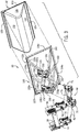
FIGS. 4A and4B are rear perspective views of the example hybrid load bucket assembly with a bucket shell shown mounted and dismounted, respectively, to a skeletal frame; -
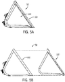
FIGS. 5A and 5B are respective side views thereof; -
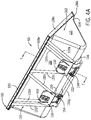
FIGS. 6A and 6B are respective front views thereof, showing the bucket shell alone inFIG. 6A and the skeleton alone inFIG. 6B ; -
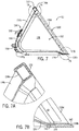
FIG. 7 is a side sectional view of the example hybrid load bucket assembly taken along line 7-7 ofFIG. 4A ; -
FIGS. 7A and 7B are detail views ofareas 7A-7A and 7B-7B, respectively, inFIG. 7 ; -
FIG. 8 is a front perspective view depicting example high load concentrations areas; and -
FIG. 9 is a front perspective view of an alternative example hybrid load bucket assembly in which the bucket shell has recessed material cavities. - Like reference symbols in the various drawings indicate like elements.
- The following describes one or more example embodiments of the disclosed hybrid load bucket assembly, as shown in the accompanying figures of the drawings described briefly above. Various modifications to the example embodiments may be contemplated by one of skill in the art.
- As used herein, unless otherwise limited or modified, lists with elements that are separated by conjunctive terms (e.g., "and") and that are also preceded by the phrase "one or more of" or "at least one of" indicate configurations or arrangements that potentially include individual elements of the list, or any combination thereof. For example, "at least one of A, B, and C" or "one or more of A, B, and C" indicates the possibilities of only A, only B, only C, or any combination of two or more of A, B, and C (e.g., A and B; B and C; A and C; or A, B, and C).
- Conventional load buckets for use in various construction and agricultural applications to haul materials (e.g., dirt, sand, aggregate and so on) are typically cast or fabricated of heavy-duty construction using high-strength materials (e.g., steel). The heavy-duty construction affords conventional load buckets the ability to undergo extreme loading and treatment during use as well as provide for high load volumes (e.g., 1, 2 or more cubic yards). In addition to the material itself, the weight of the heavy-duty bucket most be accommodated by the host machine, and specifically by its hydraulic system, to ensure that the machine performs as expected, that is will raise and lower the load bucket at the rate and range of motion desired. Further, as heavy and rugged as they are, encountering sufficient loading, abrasion or other forces can cause damage to conventional load buckets. The load buckets may yield (i.e., crack) due to impact or stress concentrations, or they may experience wear (e.g., at the lower leading or "cutting" edge of the bucket) that may impact the performance of the machine. Damage or worn load buckets may need to be replaced or repaired at significant expense or operational downtime of the machine.
- This disclosure provides an alternative to the conventional load bucket through the use of a hybrid assembly of a skeletal framework that supports a bucket shell, which defines the load volume for containing the material. In certain embodiments, this permits the bucket shell to be a light-duty construction, such as made with any suitable thin-walled or lightweight materials. For example, the disclosed hybrid load bucket assembly ("HLBA") may have a bucket shell formed of a resin material (e.g., a suitable thermo- or other plastic, such as an ABS, polypropylene, polyethylene, or high impact polystyrene material). The bucket shell could also be a composite material, such as a reinforced resin material (e.g., glass reinforced polypropylene). Such a bucket shell may be a homogeneous or composite, thin-walled (relative to conventional steel load buckets) resin formed using any suitable molding technique (e.g., rotational molding, injection molding, resin transfer molding, and so on). In this way, the disclosed HLBA may have both lightweight and low-cost attributes. It should be noted that the bucket shell may be formed with non-resin materials, such as various metals, in which case the bucket shell may also have a thin-walled, lightweight construction. Various advanced, technical materials (e.g., magnesium alloys, carbon fiber, Kevlar® and the like) may also be used. Further, it is also possible to utilize a bucket shell that has a heavy-duty construction, such as being formed of various steel materials (e.g., stainless steel or thick-walled, high-strengh and high-wear steel, as in conventional load buckets).
- In any case, the bucket shell is supported and coupled to the machine by the skeletal framework. In the case of light-duty constructions the bucket shell may be primarily supported and reinforced by the framework so that the loading realized by the bucket shell during use is carried by the framework to the machine. Further, the framework may also provide for perimetric support around the periphery of the bucket shell as well as at the leading (or cutting) edge of the HLBA, which tends to maintain the shape of the bucket shell (and thereby the load volume) as well as provide a leading edge that is more resistant to wear. The HLBA may also be configured so that the bucket shell is recessed within the framework to further reduce leading edge wear on the bucket shell.
- In certain embodiments, the framework is a structural skeleton, in some cases an exoskeleton, that includes a frame and support struts. The frame may form the perimeter support of the bucket shell, for example, having a rectangular configuration sized and shaped to correspond to the top, bottom and sides of the bucket shell. The support struts may be various structural members (e.g., solid or hollow tubular members) of straight or bent configuration that are sized, shaped and positioned to support the bucket shell. For example, the support struts may include various bent or angled struts shaped to conform (loosely or closely) to a back surface of the bucket shell so that some or all the length of these struts contact, and thus back, the bucket shell. The struts may be located, oriented and configured to back the bucket shell along areas of known or expected relatively high load concentrations, for example, in regions that are within the outer one-quarter to one-third of the lateral dimension (i.e., side-to-side dimension or width) of the HLBA. Various cross-struts may rigidly connect the bent bucket shell-conforming struts to stabilize and rigidify the framework. The network of struts and the frame may be assembled in any known way providing for a rigid, structural framework, including mechanical fasteners, adhesives, welding, brazing and so on.
- In various embodiments, the HLBA may be configured so that the bucket shell is removably mounted to the skeletal framework. For example, various mechanical fasteners, adhesives and the like may be used to secure the bucket shell to the frame and/or support struts. The bucket shell and/or the framework may also be configured with features that aid in mounting and dismounting such a removable bucket shell. For example, the bucket shell may have a mounting flange along some of or all its periphery through which the mechanical fasteners may extend when mounting to the framework. In some embodiments, the bucket shell may have an upper flange that is formed to fit over a top lateral member of the frame in hanger-like fashion. Irrespective of the configurational details, removably mounting the bucket shell allows for rapid (and as mentioned above, low-cost) replacement of the bucket shell, and thus repair of the HLBA, without necessarily separating the HLBA from the machine (i.e., by disconnecting it from the carrier to dismount it from the loader arms).
- The following describes one or more example implementations of the disclosed HLBA. The HLBA may be utilized with various machines or work vehicles, including loaders and other machines for lifting and moving various materials in the agricultural and construction industries. Referring to
FIGS. 1 and2 , in some embodiments, the HLBA may be used with anagricultural loader 10. It will be understood that the configuration of theloader 10 is presented as an example only. In this regard, the disclosed HLBA may be implemented as a front loader removably coupled to a work vehicle, such as a tractor. Other work vehicles, such as dedicated wheel loaders used in the construction industry, may benefit from the disclosed HLBA as well. - Generally, the
loader 10 includes a source of propulsion, such as anengine 12 that supplies power to atransmission 14. In one example, theengine 12 is an internal combustion engine, such as a diesel engine, that is controlled by an engine control module. Thetransmission 14 transfers power from theengine 12 to a suitable driveline coupled to one or more drivenwheels 16 of theloader 10 to enable theloader 10 to move. Theengine 12, thetransmission 14 and the rest of the driveline are supported by avehicle chassis 18, which is supported off the ground by thewheels 16. As is known to one skilled in the art, thetransmission 14 can include a suitable gear transmission, which can be operated in a variety of ranges containing one or more gears, including, but not limited to a park range, a neutral range, a reverse range, a drive range, a low range, a high range, etc. Thetransmission 14 may be controlled by a transmission control module, which is, along with the engine control module, in communication with a master controller 22 (or group of controllers). - The
controller 22 may control various aspects of the operation of theloader 10 and may be configured as a computing device with associated processor devices and memory architectures, as a hard-wired computing circuit (or circuits), as a programmable circuit, as a hydraulic, electrical or electro-hydraulic controller, or otherwise. As such, thecontroller 22 may be configured to execute various computational and control functionality with respect to the loader 10 (or other machinery). In some embodiments, thecontroller 22 may be configured to receive input signals in various formats (e.g., as hydraulic signals, voltage signals, current signals, and so on), and to output command signals in various formats (e.g., as hydraulic signals, voltage signals, current signals, mechanical movements, and so on). In some embodiments, the controller 22 (or a portion thereof) may be configured as an assembly of hydraulic components (e.g., valves, flow lines, pistons and cylinders, and so on), such that control of various devices (e.g., pumps or motors) may be effected with, and based upon, hydraulic, mechanical, or other signals and movements. - The
controller 22 may be in electronic, hydraulic, mechanical, or other communication with various other systems or devices of the loader 10 (or other machinery). For example, thecontroller 22 may be in electronic or hydraulic communication with various actuators, sensors, and other devices within (or outside of) theloader 10, including various devices associated with a hydraulic system. Thecontroller 22 may communicate with other systems or devices (including other controllers) in various known ways, including via a CAN bus (not shown) of theloader 10, via wireless or hydraulic communication means, or otherwise. An example location for thecontroller 22 is depicted inFIG. 1 . It will be understood, however, that other locations are possible including other locations on theloader 10, or various remote locations. In some embodiments, thecontroller 22 may be configured to receive input commands and to interface with an operator via a human-machine interface 26, which may be disposed inside acab 28 of theloader 10 for easy access by the operator. The human-machine interface 26 may be configured in a variety of ways and may include one or more joysticks, various switches or levers, one or more buttons, a touchscreen interface that may be overlaid on a display, a keyboard, a speaker, a microphone associated with a speech recognition system, or various other human-machine interface devices. - The
loader 10 also has a hydraulic system that includes one or more pumps and accumulators (designated generally by reference number 30), which may be driven by theengine 12 of theloader 10. Flow from thepumps 30 may be routed through various control valves and various conduits (e.g., flexible hoses) to drive various hydraulic cylinders, such ashydraulic cylinders FIG. 1 . Flow from the pumps (and accumulators) 30 may also power various other components of theloader 10. The flow from thepumps 30 may be controlled in various ways (e.g., through control of various electro-hydraulic control valves 40) to cause movement of thehydraulic cylinders loader 10. In this way, for example, movement of theHLBA 50 between various positions relative to thechassis 18 of theloader 10 may be implemented by various control signals to thepumps 30,control valves 40, and so on. - In the embodiment depicted, the
HLBA 50 is pivotally mounted to aboom assembly 60, which in this example, includes afirst loader arm 62 and asecond loader arm 64, which are interconnected via across-beam 66 to operate in parallel. Theloader arms chassis 18, directly or via another frame portion of theloader 10, at one end, and are coupled at an opposite end to theHLBA 50 via acarrier 68, which is pivoted via first and second (left and right)pivot linkages carrier 68 comprises first and second (left and right)couplers respective loader arms pivot linkages loader arms second couplers pivot linkages HLBA 50 upon actuation of thehydraulic cylinders - The hydraulic cylinders may be actuated to raise and lower the
boom assembly 60 relative to theloader 10. In the illustrated example, theboom assembly 60 includes two hydraulic cylinders, namely thehydraulic cylinder 34 coupled between thechassis 18 and thefirst loader arm 62 and a corresponding cylinder on the opposite side of the loader (not shown) coupled between thechassis 18 and thesecond loader arm 64. It should be noted that theloader 10 may have any number of hydraulic cylinders, such as one, three, etc. Each of thehydraulic cylinders 34 includes an end coupled to the chassis 18 (e.g., via a coupling pin) and an end mounted to the respective one of thefirst loader arm 62 and the second loader arm 64 (e.g., via another pin). Upon activation of thehydraulic cylinders 34, theboom assembly 60 may be moved between various positions to elevate theboom assembly 60, and thus theHLBA 50, relative to thechassis 18 of theloader 10. - One or more
hydraulic cylinders 36 are mounted to thefirst loader arm 62 and thefirst pivot linkage 70, and one or morehydraulic cylinders 38 are mounted to thesecond loader arm 64 and thesecond pivot linkage 72. In the illustrated example, theloader 10 includes a singlehydraulic cylinder first loader arm 62 and thesecond loader arm 64, respectively. Each of thehydraulic cylinders first loader arm 62 and the second loader arm 64 (via another pin) and an end mounted to the respective one of thefirst pivot linkage 70 and the second pivot linkage 72 (via another pin). Upon activation of thehydraulic cylinders HLBA 50 may be moved between various positions, namely to pivot thecarrier 68, and thereby theHLBA 50, relative to theboom assembly 60. - Thus, in the embodiment depicted, the
HLBA 50 is pivotable about thecarrier 68 of theboom assembly 60 by thehydraulic cylinders boom assembly 60 is presented as an example only. In this regard, in other contexts, a hoist boom (e.g. the boom assembly 60) may be generally viewed as a boom that is pivotally attached to a vehicle frame, and that is also pivotally attached to an end effector (e.g., the HLBA 50). Similarly, the carrier 68 (e.g., thecouplers 74, 76) may be generally viewed as a component effecting pivotal attachment of a bucket (e.g. the HLBA 50) to a vehicle frame. In this light, a tilt actuator (e.g., thehydraulic cylinders 36, 38) may be generally viewed as an actuator for pivoting a receptacle with respect to a hoist boom, and the hoist actuator (e.g. the hydraulic cylinders 34) may be generally viewed as an actuator for pivoting a hoist boom with respect to a vehicle frame. - In certain applications, sensors (e.g., pressure, flow or other sensors) may be provided to observe various conditions associated with the
loader 10. For example, the sensors may include one or more pressure sensors that observe a pressure within the hydraulic circuit, such as a pressure associated with at least one of thepumps 30, thecontrol valves 40 and/or one or morehydraulic cylinders carrier 68 and/or theHLBA 50. For example, sensors (e.g. inertial measurement sensors) may be coupled on or near theHLBA 50 to observe or measure parameters including the acceleration of theboom assembly 60 and/or theHLBA 50 and generate sensor signals, which may indicate if theboom assembly 60 and/or theHLBA 50 is accelerating or decelerating. In some embodiments, various sensors (e.g., angular position sensors) may be configured to detect the angular orientation of the HLBA 50 relative to theboom assembly 60, or to detect the angular orientation of the boom assembly relative to thechassis 18, and various other indicators of the current orientation or position of theHLBA 50. For example, rotary angular positon sensors may be used or linear position or displacement sensors may be used to determine the length of thehydraulic cylinders boom assembly 60. - The
HLBA 50 generally defines a receptacle for carrying various materials, such as dirt, rocks, wet dirt, sand, hay, etc. In one example, theHLBA 50 may receive about two cubic yards of material to over about five cubic yards of material. TheHLBA 50 is movable upon actuation of thehydraulic cylinders HLBA 50 can receive various materials. In the roll-back position, theHLBA 50 is pivoted upward relative to the earth's surface or ground by the actuation of thehydraulic cylinders HLBA 50 may be loaded with and retain the various materials. In the dump position, theHLBA 50 is pivoted downward relative to the earth's surface or ground by the actuation of thehydraulic cylinders HLBA 50 to substantially empty theHLBA 50. - Referring also to
FIGS. 3-6B , theexample HLBA 50 will now be detailed. TheHLBA 50 includes astructural skeleton 100 supporting abucket shell 102. In the illustrated example, theskeleton 100 is an exoskeleton in that it external to thebucket shell 102. The exoskeleton construction facilitates removal and replacement of thebucket shell 102 should it be damaged. However, in other contexts, the skeleton may be internal to the bucket shell, for example, with the bucket shell being constructed or formed (e.g., via an insert-molding operation) about the skeleton in which molecular bonding or mechanical fasteners are used to connect, and transfer loads from, the bucket shell to the skeleton. As noted above, thebucket shell 102 may be, and is in the illustrated example, of light-duty construction such that theskeleton 100 supports the bucket shell and provides the primary load-handling component of theHLBA 50. - The
bucket shell 102 has a relatively thin-walled construction (e.g., less than 1/4 inch) of relatively lightweight material, when compared to the plate or cast steel constructions of conventional load buckets that may have a wall-thickness of 10-20 mm (approximately 1/2 - 3/4 inches). Thebucket shell 102, and indeed theHLBA 50 overall, thus may be significantly lighter than conventional buckets of comparable size and volume. Theexample bucket shell 102 illustrated is a composite (e.g., glass reinforced polypropylene) formed of a base resin material (e.g., a suitable thermo- or other plastic such as an ABS, polypropylene, polyethylene, or high impact polystyrene material) that is impregnated with a reinforcing material (e.g., a suitable fibrous material such as glass or carbon fiber). The walls of thebucket shell 102 are approximately 6 mm thick, giving the bucket shell 102 a weight of approximately 78 kg (approximately 170 lbs.). Abucket shell 102 of such composite construction may be formed using any suitable molding technique (e.g., rotational molding, injection molding, resin transfer molding, etc.). Thebucket shell 102 may also be formed with non-resin materials, such as various metals, and still have a relatively thin-walled, lightweight construction. Further, thebucket shell 102 has a single-wall construction being a single layer of composite material throughout thebucket shell 102. However, various multi-wall configurations are envisioned. For example, the bucket shell may be a double-walled construction (i.e., two walls spaced apart in cross section). Further, thebucket shell 102 may include various internal or external reinforcing members, such as integrally formed (e.g., molded) walls, ribs or lattice structures that aid in the rigidity of thebucket shell 102. In the case of a double-walled bucket shell, the reinforcing members may be internal, extending between two outer walls forming the exterior of the bucket shell. - The
bucket shell 102 is formed in a configuration suitable to carry loads of material (e.g., gravel, dirt, etc.) similar to conventional load buckets. Specifically, thebucket shell 102 has lateral upper andlower walls walls FIG. 9 , the walls (lateral walls 110', 112' of bucket shell 102') may be formed with load cavities or recesses 114 (e.g., recesses 114a-d) that increase the carry volume of the HLBA (HLBA 50' in theFIG. 9 embodiment).Side walls walls FIG. 9 embodiment). - The walls of the
bucket shell 102 are integrally formed and connected given their molded construction. However, they may instead be separate walls joined together by a suitable mechanical connection or bonding technique (e.g., fasteners, adhesives, ultrasonic or other welding, etc.). Afront periphery 120 of thebucket shell 102 has a rectangular configuration, with, as shown inFIGS. 4B and5B , a top edge thereof having a continuous and integral right-angle flange 122 and a bottom edge that is contoured with an inflection point at which thebucket shell 102 forms a continuous and integral downwardly extendingportion 124, which angles away from the top edge out of plane with the rest of thelower wall 112. The top and bottom edge features,flange 122 andportion 124, are detailed further below. - The
skeleton 100 includes aframe 130, a network of trusses or support struts 132, and first andsecond coupling brackets frame 130 is rectangular, formed as an assembly of long 138a, 138b and short 138c, 138d straight frame members. Theframe 130 forms a support for thefront periphery 120 of thebucket shell 102 at the leading (or cutting) edge of theHLBA 50 to maintain the shape of the bucket shell 102 (and thereby the load volume). Theframe 130 may also mount to thebucket shell 102 to extend or project forward of thebucket shell 102, particularly at the lower (or cutting) edge. By recessing thebucket shell 102 into theframe 130, theHLBA 50 provides a load bucket with a leading edge that is less prone to wear, thus enhancing cutting operation of theHLBA 50 and reducing or eliminating the need to repair or replace thebucket shell 102 due to wear. As shown inFIGS. 7 and 7B , thelower frame member 138b is formed with atapered cutting edge 140, to aid in cutting, and a recessedrear edge 142 defining ashoulder 144 against which the leading edge of thelower wall 112 of thebucket shell 102 may abut or for which theshoulder 144 may act as a stopping surface. Theside frame members bucket shell 102 and effectively establish side wear plates to reduce or eliminate side wall damage and wear. - In the illustrated example, the
lower frame member 138b andframe members upper frame member 138a is also a straight structural member, although in the example embodiment, it has a hollow rectangular cross-section that is sized to fit within the right-angle flange 122 of thebucket shell 102. As shown inFIGS. 7 and 7A , theflange 122 wraps around the front- and upward-facing surfaces of theupper frame member 138a. Theflange 122 may thus provide a hanger or hook feature, which may facilitate connection of thebucket shell 102 to theskeleton 100 and in positioning thebucket shell 102 prior to application of mechanical fasteners or other connection techniques. - The
HLBA 50 is configured so that thebucket shell 102 is removably mounted to theskeleton 100. Removably mounting thebucket shell 102 facilitates rapid replacement of thebucket shell 102 if damaged or worn, and thus repair of theHLBA 50, while retaining the skeleton 100 (i.e., without discarding or replacing it if undamaged), and without necessarily separating theHLBA 50 from the machine (i.e., dismounting it from theloader arms front periphery 120 secure thebucket shell 102 to theframe members 138a-d of theframe 130. Alternatively, or additionally, adhesives and other fastening techniques may be used, and similar connections may be made between thebucket shell 102 and the support struts 132. - With the
frame 130, the support struts 132 form the structural backbone of theHLBA 50. The support struts 132 may be variously configured solid or hollow structural members of straight or bent configuration that are sized, shaped and positioned to support thebucket shell 102. In the illustrated example, there are sixsupport struts 132a-f having a bent configuration generally in the shape of a "V." The configuration of the support struts 132a-f match that of thebucket shell 102 to extend along a back side of thewalls walls FIG. 6B ) at a generally equal and opposite angle (e.g., about 30 degrees). Support struts 132c, 132d are oriented at oblique angles with respect to the respective support struts 132a, 132b and 132e, 132f, generally being mirror images on each side of the central reference planeC. Support strut 132g is a straight member extending generally perpendicular to the central reference plane C and joining the other support struts 132a-f by a rigid connection at or near the apices of the bends therein to stabilize and rigidify theskeleton 100. - Referring also to
FIG. 8 , the support struts 132 may be located, oriented and configured to back thebucket shell 102 along areas of known or expected high load concentrations, for example, in the shaded or filled regions "HL" shown. When theHLBA 50 is loaded with material, such areas of relatively high load concentrations may occur within the outer one-quarter to one-third of the lateral dimension (i.e., side-to-side dimension or width) of theHLBA 50. As can be seen, the support struts 132, and especially the strut pairs (support struts 132a, 132b and 132e, 132f), are located generally along the regions HL. As mentioned previously, front peripheral support to thebucket shell 102 is provided by theframe 130. of. The network of support struts 132 and theframe 130 may be assembled in any known way providing for a rigid, structural framework, including mechanical fasteners, adhesives, welding, brazing and the like. In the illustrated example, the lower ends of the support struts 132 couple to thelower frame member 138b at threeupstanding connection tabs 160. The upper ends of the support struts 132 connect directly to theframe member 138a. - The support struts 132, and thereby the
skeleton 100 and thebucket shell 102, connect to theloader arms coupling brackets couplers carrier 68. This connection may be releasable. In the illustrated example, thecoupling brackets plates 150 that attach to the support struts 132 and mountupper hooks 152 that open downwardly to receive from above the cross-rod 78 of thecarrier 68.Lugs 154 extend rearwardly from thecoupling brackets couplers skeleton 100 to thecarrier 68. Removing the pins, disconnects thelugs 154, while theHLBA 50 remains mounted to thecarrier 68 by engagement of thehooks 152 and the cross-rod 78. TheHLBA 50 may then be separated from theloader 10 by lowering theloader arms - The terminology used herein is for the purpose of describing particular embodiments only and is not intended to be limiting of the disclosure. As used herein, the singular forms "a", "an" and "the" are intended to include the plural forms as well, unless the context clearly indicates otherwise. It will be further understood that the terms "comprises" and/or "comprising," when used in this specification, specify the presence of stated features, integers, steps, operations, elements, and/or components, but do not preclude the presence or addition of one or more other features, integers, steps, operations, elements, components, and/or groups thereof.
- The description of the present disclosure has been presented for purposes of illustration and description, but is not intended to be exhaustive or limited to the disclosure in the form disclosed. Many modifications and variations will be apparent to those of ordinary skill in the art without departing from the scope and spirit of the disclosure. Explicitly referenced embodiments herein were chosen and described to best explain the principles of the disclosure and their practical application, and to enable others of ordinary skill in the art to understand the disclosure and recognize many alternatives, modifications, and variations on the described example(s). Accordingly, various embodiments and implementations other than those explicitly described are within the scope of the following claims.
Claims (15)
- A hybrid bucket assembly for a work vehicle having movable loader arms (62, 64), the bucket assembly comprising:a structural skeleton (100) having a frame (130), one or more support struts (132, 132a, 132b, 132c, 132d, 132e, 132f) mounted to the frame (130), and one or more brackets (134, 136) coupled to the support struts (132, 132a, 132b, 132c, 132d, 132e, 132f) configured to interface with a carrier (68) at distal ends of the loader arms (62, 64); anda bucket shell (102) mounted to the skeleton (100) and defining a carry volume for materials;wherein force loading on the bucket shell (102) is carried by the skeleton (100) through the struts (132, 132a, 132b, 132c, 132d, 132e, 132f).
- The assembly of claim 1, wherein the bucket shell (102) is a resin material.
- The assembly of claim 1 or 2, wherein the bucket shell (102) is a composite reinforced resin material.
- The assembly in accordance with at least any one of the preceding claims,
wherein the bucket shell (102) is removably mounted to the skeleton (100). - The assembly in accordance with at least any one of the preceding claims,
wherein the bucket shell (102) is mounted to the frame (130) via mechanical fasteners. - The assembly in accordance with at least any one of the preceding claims,
wherein the bucket shell (102) is recessed within the frame (130) such that at least a lower lateral member of the frame (130) has a leading edge that projects beyond a lower lateral leading edge of the bucket shell (102). - The assembly in accordance with at least any one of the preceding claims,
wherein the frame (130) has a recessed inner periphery and defines a shoulder against which abuts the lower lateral leading edge of the bucket shell (102). - The assembly in accordance with at least any one of the preceding claims,
wherein the frame (130) has a tubular upper lateral member; and
wherein the bucket shell (102) has an upper lateral flange suspended on the upper lateral member of the frame (130). - The assembly in accordance with at least any one of the preceding claims,
wherein some of the struts (132, 132a, 132b, 132c, 132d, 132e, 132f) are shell-conforming struts
that have opposite ends coupled to the frame (130) and have lengths that follow one or more outer surfaces of the bucket shell (102);
wherein the one or more outer surfaces of the bucket shell (102) contact the shell-conforming struts along the lengths of the shell-conforming struts from the lower lateral member to the upper lateral member of the frame. - The assembly in accordance with at least any one of the preceding claims,
wherein the shell-conforming struts are spaced apart laterally with at least one shell-conforming strut in a first lateral third of the bucket, at least one bent strut in a second lateral third of the bucket, and at least one in a third lateral third of the bucket. - The assembly in accordance with at least any one of the preceding claims,
wherein the shell-conforming struts are arranged at one or more oblique angles with respect to a fore-aft centerline of the bucket. - The assembly in accordance with at least any one of the preceding claims,
wherein at least one of the struts (132, 132a, 132b, 132c, 132d, 132e, 132f) is a lateral strut that ties together the shell-conforming struts. - A work vehicle comprising:a chassis (18);loader arms (62, 64) movably mounted to the chassis (18);a carrier (68) mounted to distal ends of the loader arms (62, 64); anda hybrid bucket assembly having:a structural skeleton (100) having a frame (130), one or more support struts (132, 132a, 132b, 132c, 132d, 132e, 132f) mounted to the frame (130), and one or more brackets (134, 136) coupled to the support struts (132, 132a, 132b, 132c, 132d, 132e, 132f) and mountable to the carrier (68); anda bucket shell (102) mounted to the skeleton (100) and defining a carry volume for materials;wherein force loading on the bucket shell (102) is carried by the skeleton (100) through the struts (132, 132a, 132b, 132c, 132d, 132e, 132f).
- The work vehicle of claim 13, wherein the bucket shell (102) is a composite reinforced resin material removably mounted to the skeleton (100) via mechanical fasteners; and
wherein the skeleton (100) is made of at least one of structural steel, aluminum and carbon fiber. - The work vehicle of claim 13 or 14, wherein the bucket shell (102) is recessed within the frame (130) such that at least a lower lateral member of the frame (130) has a leading edge that projects beyond a lower lateral leading edge of the bucket shell (102); and
wherein the frame (130) has a tubular upper lateral member and the bucket shell (102) has an upper lateral flange suspended on the upper lateral member of the frame (130).
Applications Claiming Priority (1)
| Application Number | Priority Date | Filing Date | Title |
|---|---|---|---|
| US15/805,476 US10662610B2 (en) | 2017-11-07 | 2017-11-07 | Hybrid load bucket assembly |
Publications (2)
| Publication Number | Publication Date |
|---|---|
| EP3480370A1 true EP3480370A1 (en) | 2019-05-08 |
| EP3480370B1 EP3480370B1 (en) | 2021-10-06 |
Family
ID=64267476
Family Applications (1)
| Application Number | Title | Priority Date | Filing Date |
|---|---|---|---|
| EP18204521.1A Active EP3480370B1 (en) | 2017-11-07 | 2018-11-06 | Hybrid load bucket assembly |
Country Status (3)
| Country | Link |
|---|---|
| US (3) | US10662610B2 (en) |
| EP (1) | EP3480370B1 (en) |
| CA (1) | CA3019825C (en) |
Families Citing this family (4)
| Publication number | Priority date | Publication date | Assignee | Title |
|---|---|---|---|---|
| US11078644B2 (en) * | 2018-04-11 | 2021-08-03 | Deere & Company | Hybrid load bucket assembly |
| US11525237B2 (en) * | 2018-08-31 | 2022-12-13 | Clark Equipment Company | Loader bucket |
| US12227918B2 (en) | 2020-12-31 | 2025-02-18 | Caterpillar Global Mining Llc | Dipper lattice frame and wearable structural liner |
| US11952743B2 (en) | 2021-10-15 | 2024-04-09 | Deere & Company | Loader with moving apparatus |
Citations (2)
| Publication number | Priority date | Publication date | Assignee | Title |
|---|---|---|---|---|
| US5267402A (en) * | 1992-11-17 | 1993-12-07 | Russell Lee A | Bucket assembly for a tractor |
| DE202010002040U1 (en) * | 2010-02-09 | 2010-05-27 | Lrt Gmbh Tharandter Baumaschinenservice | Construction equipment |
Family Cites Families (14)
| Publication number | Priority date | Publication date | Assignee | Title |
|---|---|---|---|---|
| US2228447A (en) * | 1940-01-15 | 1941-01-14 | Evelev Michael | Vegetable harvester |
| US3807587A (en) * | 1972-03-27 | 1974-04-30 | Case Co J I | Material handling bucket |
| US4086712A (en) * | 1977-03-31 | 1978-05-02 | Caterpillar Tractor Co. | Bucket construction having improved reinforcing means |
| SE9602798L (en) * | 1996-07-17 | 1998-01-18 | Stig Pettersson | Bucket |
| US5901479A (en) * | 1997-07-29 | 1999-05-11 | Langdon; Dess | Bucket for a front-end loader |
| US6098321A (en) * | 1999-05-07 | 2000-08-08 | Logan; John Duncan | Bucket converter for an excavation bucket |
| US20050036875A1 (en) | 2003-08-15 | 2005-02-17 | Bruce Downing | Bucket attachment for loader |
| US7360327B2 (en) * | 2004-02-12 | 2008-04-22 | Ralph L. Osgood, Inc. | Material moving pusher/bucket |
| US7484321B1 (en) * | 2006-08-09 | 2009-02-03 | Stafne Sr John D | Anti-freeze backhoe bucket insert |
| US7718724B2 (en) | 2007-03-14 | 2010-05-18 | Alcatel-Lucent Usa Inc. | Thermoplastic composite materials for wear surfaces and methods for making same |
| US8827627B2 (en) | 2010-03-05 | 2014-09-09 | Ronnie Joseph Landry | Rotatable bucket for attachment to three point hitch of tractor |
| WO2015196251A1 (en) | 2014-06-23 | 2015-12-30 | Peach Bryan | Narrow trencher bucket |
| US10024027B2 (en) * | 2016-08-23 | 2018-07-17 | Caterpillar Inc. | Multi-component shell profile for a bucket |
| US10378188B2 (en) * | 2016-09-23 | 2019-08-13 | Rockland Manufacturing Company | Bucket, blade, liner, or chute with visual wear indicator |
-
2017
- 2017-11-07 US US15/805,476 patent/US10662610B2/en active Active
-
2018
- 2018-10-05 CA CA3019825A patent/CA3019825C/en active Active
- 2018-11-06 EP EP18204521.1A patent/EP3480370B1/en active Active
-
2020
- 2020-04-30 US US16/863,211 patent/US11015318B2/en active Active
-
2021
- 2021-05-25 US US17/329,457 patent/US12071740B2/en active Active
Patent Citations (2)
| Publication number | Priority date | Publication date | Assignee | Title |
|---|---|---|---|---|
| US5267402A (en) * | 1992-11-17 | 1993-12-07 | Russell Lee A | Bucket assembly for a tractor |
| DE202010002040U1 (en) * | 2010-02-09 | 2010-05-27 | Lrt Gmbh Tharandter Baumaschinenservice | Construction equipment |
Also Published As
| Publication number | Publication date |
|---|---|
| US12071740B2 (en) | 2024-08-27 |
| US11015318B2 (en) | 2021-05-25 |
| US20190136484A1 (en) | 2019-05-09 |
| EP3480370B1 (en) | 2021-10-06 |
| CA3019825A1 (en) | 2019-05-07 |
| US20200256033A1 (en) | 2020-08-13 |
| CA3019825C (en) | 2020-10-20 |
| US20210277622A1 (en) | 2021-09-09 |
| US10662610B2 (en) | 2020-05-26 |
Similar Documents
| Publication | Publication Date | Title |
|---|---|---|
| US12071740B2 (en) | Hybrid load bucket assembly | |
| US7824145B2 (en) | Common pivot and support member for attachment interface | |
| EP3553232B1 (en) | Hybrid load bucket assembly | |
| CN108713081B (en) | Wheel Loader Front Unit and Wheel Loader | |
| CN114396089B (en) | Wheel loader front unit and wheel loader | |
| CN108602539B (en) | Crawler-type multifunctional vehicle | |
| JPH04316405A (en) | Structure for attaching front loader of tractor | |
| US10662609B2 (en) | Hybrid loader boom arm assembly | |
| US10822768B2 (en) | Hybrid loader boom arm assembly | |
| WO2014098652A1 (en) | Front frame arrangement for a working machine and a wheel loader | |
| EP3553230A1 (en) | Hybrid loader boom arm assembly | |
| US10697148B2 (en) | Hybrid loader boom arm assembly | |
| US10294629B1 (en) | Holder for coupling a work implement to a work vehicle | |
| US11608839B2 (en) | Bracket mount for engine with pump package | |
| CN116065645A (en) | Work machine | |
| JP6452371B2 (en) | Working machine | |
| CN202245938U (en) | Small-sized multifunctional overland forklift | |
| CN207064066U (en) | Dynamic power machine | |
| GB2634788A (en) | A material handling machine | |
| JP2016069997A (en) | Work machine |
Legal Events
| Date | Code | Title | Description |
|---|---|---|---|
| PUAI | Public reference made under article 153(3) epc to a published international application that has entered the european phase |
Free format text: ORIGINAL CODE: 0009012 |
|
| STAA | Information on the status of an ep patent application or granted ep patent |
Free format text: STATUS: THE APPLICATION HAS BEEN PUBLISHED |
|
| AK | Designated contracting states |
Kind code of ref document: A1 Designated state(s): AL AT BE BG CH CY CZ DE DK EE ES FI FR GB GR HR HU IE IS IT LI LT LU LV MC MK MT NL NO PL PT RO RS SE SI SK SM TR |
|
| AX | Request for extension of the european patent |
Extension state: BA ME |
|
| STAA | Information on the status of an ep patent application or granted ep patent |
Free format text: STATUS: REQUEST FOR EXAMINATION WAS MADE |
|
| 17P | Request for examination filed |
Effective date: 20191108 |
|
| RBV | Designated contracting states (corrected) |
Designated state(s): AL AT BE BG CH CY CZ DE DK EE ES FI FR GB GR HR HU IE IS IT LI LT LU LV MC MK MT NL NO PL PT RO RS SE SI SK SM TR |
|
| GRAP | Despatch of communication of intention to grant a patent |
Free format text: ORIGINAL CODE: EPIDOSNIGR1 |
|
| STAA | Information on the status of an ep patent application or granted ep patent |
Free format text: STATUS: GRANT OF PATENT IS INTENDED |
|
| INTG | Intention to grant announced |
Effective date: 20210504 |
|
| GRAS | Grant fee paid |
Free format text: ORIGINAL CODE: EPIDOSNIGR3 |
|
| GRAA | (expected) grant |
Free format text: ORIGINAL CODE: 0009210 |
|
| STAA | Information on the status of an ep patent application or granted ep patent |
Free format text: STATUS: THE PATENT HAS BEEN GRANTED |
|
| AK | Designated contracting states |
Kind code of ref document: B1 Designated state(s): AL AT BE BG CH CY CZ DE DK EE ES FI FR GB GR HR HU IE IS IT LI LT LU LV MC MK MT NL NO PL PT RO RS SE SI SK SM TR |
|
| REG | Reference to a national code |
Ref country code: GB Ref legal event code: FG4D |
|
| REG | Reference to a national code |
Ref country code: CH Ref legal event code: EP Ref country code: AT Ref legal event code: REF Ref document number: 1436345 Country of ref document: AT Kind code of ref document: T Effective date: 20211015 |
|
| REG | Reference to a national code |
Ref country code: IE Ref legal event code: FG4D |
|
| REG | Reference to a national code |
Ref country code: DE Ref legal event code: R096 Ref document number: 602018024565 Country of ref document: DE |
|
| REG | Reference to a national code |
Ref country code: LT Ref legal event code: MG9D |
|
| REG | Reference to a national code |
Ref country code: NL Ref legal event code: MP Effective date: 20211006 |
|
| REG | Reference to a national code |
Ref country code: AT Ref legal event code: MK05 Ref document number: 1436345 Country of ref document: AT Kind code of ref document: T Effective date: 20211006 |
|
| PG25 | Lapsed in a contracting state [announced via postgrant information from national office to epo] |
Ref country code: RS Free format text: LAPSE BECAUSE OF FAILURE TO SUBMIT A TRANSLATION OF THE DESCRIPTION OR TO PAY THE FEE WITHIN THE PRESCRIBED TIME-LIMIT Effective date: 20211006 Ref country code: LT Free format text: LAPSE BECAUSE OF FAILURE TO SUBMIT A TRANSLATION OF THE DESCRIPTION OR TO PAY THE FEE WITHIN THE PRESCRIBED TIME-LIMIT Effective date: 20211006 Ref country code: FI Free format text: LAPSE BECAUSE OF FAILURE TO SUBMIT A TRANSLATION OF THE DESCRIPTION OR TO PAY THE FEE WITHIN THE PRESCRIBED TIME-LIMIT Effective date: 20211006 Ref country code: BG Free format text: LAPSE BECAUSE OF FAILURE TO SUBMIT A TRANSLATION OF THE DESCRIPTION OR TO PAY THE FEE WITHIN THE PRESCRIBED TIME-LIMIT Effective date: 20220106 Ref country code: AT Free format text: LAPSE BECAUSE OF FAILURE TO SUBMIT A TRANSLATION OF THE DESCRIPTION OR TO PAY THE FEE WITHIN THE PRESCRIBED TIME-LIMIT Effective date: 20211006 |
|
| PG25 | Lapsed in a contracting state [announced via postgrant information from national office to epo] |
Ref country code: IS Free format text: LAPSE BECAUSE OF FAILURE TO SUBMIT A TRANSLATION OF THE DESCRIPTION OR TO PAY THE FEE WITHIN THE PRESCRIBED TIME-LIMIT Effective date: 20220206 Ref country code: SE Free format text: LAPSE BECAUSE OF FAILURE TO SUBMIT A TRANSLATION OF THE DESCRIPTION OR TO PAY THE FEE WITHIN THE PRESCRIBED TIME-LIMIT Effective date: 20211006 Ref country code: PT Free format text: LAPSE BECAUSE OF FAILURE TO SUBMIT A TRANSLATION OF THE DESCRIPTION OR TO PAY THE FEE WITHIN THE PRESCRIBED TIME-LIMIT Effective date: 20220207 Ref country code: PL Free format text: LAPSE BECAUSE OF FAILURE TO SUBMIT A TRANSLATION OF THE DESCRIPTION OR TO PAY THE FEE WITHIN THE PRESCRIBED TIME-LIMIT Effective date: 20211006 Ref country code: NO Free format text: LAPSE BECAUSE OF FAILURE TO SUBMIT A TRANSLATION OF THE DESCRIPTION OR TO PAY THE FEE WITHIN THE PRESCRIBED TIME-LIMIT Effective date: 20220106 Ref country code: NL Free format text: LAPSE BECAUSE OF FAILURE TO SUBMIT A TRANSLATION OF THE DESCRIPTION OR TO PAY THE FEE WITHIN THE PRESCRIBED TIME-LIMIT Effective date: 20211006 Ref country code: LV Free format text: LAPSE BECAUSE OF FAILURE TO SUBMIT A TRANSLATION OF THE DESCRIPTION OR TO PAY THE FEE WITHIN THE PRESCRIBED TIME-LIMIT Effective date: 20211006 Ref country code: HR Free format text: LAPSE BECAUSE OF FAILURE TO SUBMIT A TRANSLATION OF THE DESCRIPTION OR TO PAY THE FEE WITHIN THE PRESCRIBED TIME-LIMIT Effective date: 20211006 Ref country code: GR Free format text: LAPSE BECAUSE OF FAILURE TO SUBMIT A TRANSLATION OF THE DESCRIPTION OR TO PAY THE FEE WITHIN THE PRESCRIBED TIME-LIMIT Effective date: 20220107 Ref country code: ES Free format text: LAPSE BECAUSE OF FAILURE TO SUBMIT A TRANSLATION OF THE DESCRIPTION OR TO PAY THE FEE WITHIN THE PRESCRIBED TIME-LIMIT Effective date: 20211006 |
|
| REG | Reference to a national code |
Ref country code: DE Ref legal event code: R097 Ref document number: 602018024565 Country of ref document: DE |
|
| REG | Reference to a national code |
Ref country code: CH Ref legal event code: PL |
|
| PG25 | Lapsed in a contracting state [announced via postgrant information from national office to epo] |
Ref country code: SM Free format text: LAPSE BECAUSE OF FAILURE TO SUBMIT A TRANSLATION OF THE DESCRIPTION OR TO PAY THE FEE WITHIN THE PRESCRIBED TIME-LIMIT Effective date: 20211006 Ref country code: SK Free format text: LAPSE BECAUSE OF FAILURE TO SUBMIT A TRANSLATION OF THE DESCRIPTION OR TO PAY THE FEE WITHIN THE PRESCRIBED TIME-LIMIT Effective date: 20211006 Ref country code: RO Free format text: LAPSE BECAUSE OF FAILURE TO SUBMIT A TRANSLATION OF THE DESCRIPTION OR TO PAY THE FEE WITHIN THE PRESCRIBED TIME-LIMIT Effective date: 20211006 Ref country code: MC Free format text: LAPSE BECAUSE OF FAILURE TO SUBMIT A TRANSLATION OF THE DESCRIPTION OR TO PAY THE FEE WITHIN THE PRESCRIBED TIME-LIMIT Effective date: 20211006 Ref country code: LU Free format text: LAPSE BECAUSE OF NON-PAYMENT OF DUE FEES Effective date: 20211106 Ref country code: EE Free format text: LAPSE BECAUSE OF FAILURE TO SUBMIT A TRANSLATION OF THE DESCRIPTION OR TO PAY THE FEE WITHIN THE PRESCRIBED TIME-LIMIT Effective date: 20211006 Ref country code: DK Free format text: LAPSE BECAUSE OF FAILURE TO SUBMIT A TRANSLATION OF THE DESCRIPTION OR TO PAY THE FEE WITHIN THE PRESCRIBED TIME-LIMIT Effective date: 20211006 Ref country code: CZ Free format text: LAPSE BECAUSE OF FAILURE TO SUBMIT A TRANSLATION OF THE DESCRIPTION OR TO PAY THE FEE WITHIN THE PRESCRIBED TIME-LIMIT Effective date: 20211006 Ref country code: BE Free format text: LAPSE BECAUSE OF NON-PAYMENT OF DUE FEES Effective date: 20211130 |
|
| REG | Reference to a national code |
Ref country code: BE Ref legal event code: MM Effective date: 20211130 |
|
| PLBE | No opposition filed within time limit |
Free format text: ORIGINAL CODE: 0009261 |
|
| STAA | Information on the status of an ep patent application or granted ep patent |
Free format text: STATUS: NO OPPOSITION FILED WITHIN TIME LIMIT |
|
| 26N | No opposition filed |
Effective date: 20220707 |
|
| PG25 | Lapsed in a contracting state [announced via postgrant information from national office to epo] |
Ref country code: IE Free format text: LAPSE BECAUSE OF NON-PAYMENT OF DUE FEES Effective date: 20211106 Ref country code: AL Free format text: LAPSE BECAUSE OF FAILURE TO SUBMIT A TRANSLATION OF THE DESCRIPTION OR TO PAY THE FEE WITHIN THE PRESCRIBED TIME-LIMIT Effective date: 20211006 |
|
| PG25 | Lapsed in a contracting state [announced via postgrant information from national office to epo] |
Ref country code: SI Free format text: LAPSE BECAUSE OF FAILURE TO SUBMIT A TRANSLATION OF THE DESCRIPTION OR TO PAY THE FEE WITHIN THE PRESCRIBED TIME-LIMIT Effective date: 20211006 |
|
| PG25 | Lapsed in a contracting state [announced via postgrant information from national office to epo] |
Ref country code: IT Free format text: LAPSE BECAUSE OF FAILURE TO SUBMIT A TRANSLATION OF THE DESCRIPTION OR TO PAY THE FEE WITHIN THE PRESCRIBED TIME-LIMIT Effective date: 20211006 |
|
| PG25 | Lapsed in a contracting state [announced via postgrant information from national office to epo] |
Ref country code: CY Free format text: LAPSE BECAUSE OF FAILURE TO SUBMIT A TRANSLATION OF THE DESCRIPTION OR TO PAY THE FEE WITHIN THE PRESCRIBED TIME-LIMIT Effective date: 20211006 |
|
| PG25 | Lapsed in a contracting state [announced via postgrant information from national office to epo] |
Ref country code: LI Free format text: LAPSE BECAUSE OF NON-PAYMENT OF DUE FEES Effective date: 20220701 Ref country code: HU Free format text: LAPSE BECAUSE OF FAILURE TO SUBMIT A TRANSLATION OF THE DESCRIPTION OR TO PAY THE FEE WITHIN THE PRESCRIBED TIME-LIMIT; INVALID AB INITIO Effective date: 20181106 Ref country code: CH Free format text: LAPSE BECAUSE OF NON-PAYMENT OF DUE FEES Effective date: 20220701 |
|
| PG25 | Lapsed in a contracting state [announced via postgrant information from national office to epo] |
Ref country code: MK Free format text: LAPSE BECAUSE OF FAILURE TO SUBMIT A TRANSLATION OF THE DESCRIPTION OR TO PAY THE FEE WITHIN THE PRESCRIBED TIME-LIMIT Effective date: 20211006 |
|
| PG25 | Lapsed in a contracting state [announced via postgrant information from national office to epo] |
Ref country code: TR Free format text: LAPSE BECAUSE OF FAILURE TO SUBMIT A TRANSLATION OF THE DESCRIPTION OR TO PAY THE FEE WITHIN THE PRESCRIBED TIME-LIMIT Effective date: 20211006 |
|
| PG25 | Lapsed in a contracting state [announced via postgrant information from national office to epo] |
Ref country code: MT Free format text: LAPSE BECAUSE OF FAILURE TO SUBMIT A TRANSLATION OF THE DESCRIPTION OR TO PAY THE FEE WITHIN THE PRESCRIBED TIME-LIMIT Effective date: 20211006 |
|
| PGFP | Annual fee paid to national office [announced via postgrant information from national office to epo] |
Ref country code: DE Payment date: 20251021 Year of fee payment: 8 |
|
| PGFP | Annual fee paid to national office [announced via postgrant information from national office to epo] |
Ref country code: GB Payment date: 20251127 Year of fee payment: 8 |
|
| PGFP | Annual fee paid to national office [announced via postgrant information from national office to epo] |
Ref country code: FR Payment date: 20251125 Year of fee payment: 8 |