EP3480111B1 - Slouching divan with damped motion - Google Patents
Slouching divan with damped motion Download PDFInfo
- Publication number
- EP3480111B1 EP3480111B1 EP18203970.1A EP18203970A EP3480111B1 EP 3480111 B1 EP3480111 B1 EP 3480111B1 EP 18203970 A EP18203970 A EP 18203970A EP 3480111 B1 EP3480111 B1 EP 3480111B1
- Authority
- EP
- European Patent Office
- Prior art keywords
- seatpan
- divan
- slouching
- backrest
- degrees
- Prior art date
- Legal status (The legal status is an assumption and is not a legal conclusion. Google has not performed a legal analysis and makes no representation as to the accuracy of the status listed.)
- Active
Links
- 230000033001 locomotion Effects 0.000 title claims description 14
- 238000013016 damping Methods 0.000 claims description 24
- 210000001364 upper extremity Anatomy 0.000 claims description 15
- 230000004044 response Effects 0.000 claims description 4
- 230000002265 prevention Effects 0.000 claims description 3
- 230000007704 transition Effects 0.000 description 11
- 230000007246 mechanism Effects 0.000 description 5
- 238000000034 method Methods 0.000 description 4
- 230000005484 gravity Effects 0.000 description 3
- 230000001105 regulatory effect Effects 0.000 description 3
- 230000008901 benefit Effects 0.000 description 2
- 230000008569 process Effects 0.000 description 2
- 230000001154 acute effect Effects 0.000 description 1
- 238000006243 chemical reaction Methods 0.000 description 1
- 238000010276 construction Methods 0.000 description 1
- 239000011521 glass Substances 0.000 description 1
- 238000009499 grossing Methods 0.000 description 1
- 230000002452 interceptive effect Effects 0.000 description 1
- 210000003141 lower extremity Anatomy 0.000 description 1
- 230000000284 resting effect Effects 0.000 description 1
- 230000002441 reversible effect Effects 0.000 description 1
Images


Classifications
-
- B—PERFORMING OPERATIONS; TRANSPORTING
- B64—AIRCRAFT; AVIATION; COSMONAUTICS
- B64D—EQUIPMENT FOR FITTING IN OR TO AIRCRAFT; FLIGHT SUITS; PARACHUTES; ARRANGEMENTS OR MOUNTING OF POWER PLANTS OR PROPULSION TRANSMISSIONS IN AIRCRAFT
- B64D11/00—Passenger or crew accommodation; Flight-deck installations not otherwise provided for
- B64D11/06—Arrangements of seats, or adaptations or details specially adapted for aircraft seats
- B64D11/0619—Arrangements of seats, or adaptations or details specially adapted for aircraft seats with energy absorbing means specially adapted for mitigating impact loads for passenger seats, e.g. at a crash
-
- B—PERFORMING OPERATIONS; TRANSPORTING
- B64—AIRCRAFT; AVIATION; COSMONAUTICS
- B64D—EQUIPMENT FOR FITTING IN OR TO AIRCRAFT; FLIGHT SUITS; PARACHUTES; ARRANGEMENTS OR MOUNTING OF POWER PLANTS OR PROPULSION TRANSMISSIONS IN AIRCRAFT
- B64D11/00—Passenger or crew accommodation; Flight-deck installations not otherwise provided for
- B64D11/06—Arrangements of seats, or adaptations or details specially adapted for aircraft seats
- B64D11/062—Belts or other passenger restraint means for passenger seats
- B64D11/06205—Arrangements of airbags
- B64D11/0621—Airbag initiation or activation means
-
- B—PERFORMING OPERATIONS; TRANSPORTING
- B64—AIRCRAFT; AVIATION; COSMONAUTICS
- B64D—EQUIPMENT FOR FITTING IN OR TO AIRCRAFT; FLIGHT SUITS; PARACHUTES; ARRANGEMENTS OR MOUNTING OF POWER PLANTS OR PROPULSION TRANSMISSIONS IN AIRCRAFT
- B64D11/00—Passenger or crew accommodation; Flight-deck installations not otherwise provided for
- B64D11/06—Arrangements of seats, or adaptations or details specially adapted for aircraft seats
- B64D11/0639—Arrangements of seats, or adaptations or details specially adapted for aircraft seats with features for adjustment or converting of seats
- B64D11/064—Adjustable inclination or position of seats
-
- B—PERFORMING OPERATIONS; TRANSPORTING
- B64—AIRCRAFT; AVIATION; COSMONAUTICS
- B64D—EQUIPMENT FOR FITTING IN OR TO AIRCRAFT; FLIGHT SUITS; PARACHUTES; ARRANGEMENTS OR MOUNTING OF POWER PLANTS OR PROPULSION TRANSMISSIONS IN AIRCRAFT
- B64D11/00—Passenger or crew accommodation; Flight-deck installations not otherwise provided for
- B64D11/06—Arrangements of seats, or adaptations or details specially adapted for aircraft seats
- B64D11/0639—Arrangements of seats, or adaptations or details specially adapted for aircraft seats with features for adjustment or converting of seats
- B64D11/0641—Seats convertible into beds
-
- B—PERFORMING OPERATIONS; TRANSPORTING
- B64—AIRCRAFT; AVIATION; COSMONAUTICS
- B64D—EQUIPMENT FOR FITTING IN OR TO AIRCRAFT; FLIGHT SUITS; PARACHUTES; ARRANGEMENTS OR MOUNTING OF POWER PLANTS OR PROPULSION TRANSMISSIONS IN AIRCRAFT
- B64D11/00—Passenger or crew accommodation; Flight-deck installations not otherwise provided for
- B64D11/06—Arrangements of seats, or adaptations or details specially adapted for aircraft seats
- B64D11/0696—Means for fastening seats to floors, e.g. to floor rails
-
- B—PERFORMING OPERATIONS; TRANSPORTING
- B64—AIRCRAFT; AVIATION; COSMONAUTICS
- B64D—EQUIPMENT FOR FITTING IN OR TO AIRCRAFT; FLIGHT SUITS; PARACHUTES; ARRANGEMENTS OR MOUNTING OF POWER PLANTS OR PROPULSION TRANSMISSIONS IN AIRCRAFT
- B64D11/00—Passenger or crew accommodation; Flight-deck installations not otherwise provided for
- B64D11/06—Arrangements of seats, or adaptations or details specially adapted for aircraft seats
- B64D11/062—Belts or other passenger restraint means for passenger seats
Definitions
- Modem business and executive aircraft may incorporate, in addition to or instead of conventional forward-facing single-passenger seating associated with commercial aircraft, convertible seating configurations able to be reconfigured to allow the occupying passengers to sleep in a prone or near-prone position while inflight.
- divans e.g., sofas, couches, settees
- Such an aircraft divan may be configured for compliance with any applicable seating regulations, e.g., equipped with seatbelts or harnesses to restrain the occupying passengers in an upright position during taxi, takeoff, and landing (TToL) phases or flight segments.
- the passenger/s may reposition or reconfigure the divan from an upright seated position (e.g., where the seatpan of the divan is substantially parallel to the aircraft floor and the backrest of the divan is substantially perpendicular, or at a slightly obtuse angle, thereto) to a fully extended, or berthed, position wherein the seatpan and backrest of the divan are substantially coplanar with each other and substantially parallel to the aircraft floor.
- an upright seated position e.g., where the seatpan of the divan is substantially parallel to the aircraft floor and the backrest of the divan is substantially perpendicular, or at a slightly obtuse angle, thereto
- United States patent application US 2017/021930 A1 discloses a cradle recline mechanism for an aircraft passenger seat including a guide mechanism for guiding a seat bottom of the aircraft passenger seat forward and lower as the seat bottom moves from an upright sitting position to a cradle recline sitting position, where a rear portion of the seat bottom is lowered more than a front portion of the seat bottom, causing the seat bottom to angle upwards from a bottom edge of the seat back.
- a seat back of the passenger seat may be pivotably connected to the seat bottom such that it is pulled forward and down with the movement of the seat bottom, with the recline angle determined by a rigid support mechanism disposed behind the seat back.
- Passenger weight may be counterbalanced using a moveable control mechanism such as a locking gas spring.
- European patent application EP 0 869 060 A1 discloses a seat for an aircraft having an open outer shell which embraces a seat portion, a seat back, a headrest and a footrest when the seat is in an upright position.
- the seat is reclinable into a bed configuration such that the seat portion is moved forwardly out of the open end of the shell.
- United States patent application US 2007/262625 A1 discloses a seating unit for an aircraft cabin and comprising a fixed housing containing a primary seat with a reclinable back arranged to recline in such a manner that it remains within the housing.
- the seat comprises a leg-rest arranged to cooperate with the seating portion to form part of a substantially flat surface when the back is reclined in a substantially horizontal position.
- the seating unit comprises a secondary seat having a seating portion positioned to cooperate with the leg-rest of the primary seat to form a portion of the substantially flat surface when the back of the primary seat is reclined in the substantially horizontal position.
- An occupying passenger may additionally reposition the divan to one or more intermediate reclining or "slouching" positions between the upright position and the berthed position.
- a slouched position may be characterized by a seatpan at a slightly acute angle to the aircraft floor (e.g., wherein the rear end of the seatpan has dropped from its upright position, the front end of the seatpan has remained in its upright position, and the angle of the backrest to the aircraft floor has slightly increased).
- intermediate positions between the upright and berthed positions may require complex and heavy locking and articulation equipment for securing the divan in the desired intermediate position.
- the divan may be configured for transition from the upright to the slouched position at least partially assisted by gravity and/or the weight of the occupying passenger.
- the transition from the upright to the slouched position which may involve tracking the rear end of the seatpan along a downward path, may be uncomfortably rapid for the occupying passenger; similarly, achieving the slouched position may result in an abrupt jolt for the occupying passenger.
- embodiments of the inventive concepts disclosed herein are directed to a slouching divan (e.g., couch) installable aboard an aircraft.
- the divan may be of single-, double-, or triple-passenger size and transitionable between three discrete configurations-upright/seated, slouched (e.g., reclined), and berthed (e.g., fully extended for sleeping)-and may regulate the transition between configurations via motion dampers.
- the divan is mountable to the aircraft floor (e.g., forward-facing, aft-facing, or inboard-facing) via front and rear legs.
- the front and rear legs are connected by frame rails, the frame rails including lateral slots extending from a rear end downward to a midpoint, and then up from the midpoint toward a front end.
- a seatpan (upon which a seatpan cushion may provide additional comfort for occupying passengers) may incorporate rollers traveling within the lateral slots.
- the divan may be in the upright, slouched, or berthed configuration.
- the seatpan may include seatpan rails at the right and left sides.
- the divan has a backrest also including roller slots extending from the top of the backrest down to the bottom in a path that curves to the rear.
- the divan includes a back follower panel (to which a backrest cushion may be attached) connected to the seatpan and connected to the backrest by rollers or bearings.
- the back follower panel follows the seatpan as it tracks forward along the lateral slots; the curvature in the backrest roller slots allows the back follower panel to track forward far enough that the backrest and seatpan cushions provide a flat surface (e.g., parallel to the floor) for the occupying passengers to rest upon.
- the divan may incorporate one-way damping devices to regulate the speed with which the seatpan rollers track forward and downward, and the suddenness with which the rollers stop tracking when the midpoint of the lateral slots is reached and the divan achieves the slouched configuration.
- the damping devices are one-way in that they do not interfere with the stowing of the divan from the slouched configuration back to the upright configuration (e.g., for taxi, takeoff and landing procedures).
- inventive concepts are not limited in their application to the details of construction and the arrangement of the components or steps or methodologies set forth in the following description or illustrated in the drawings.
- the current invention is limited only by the appended claim 1.
- inventive concepts disclosed herein may be practiced without these specific details.
- well-known features may not be described in detail to avoid unnecessarily complicating the instant disclosure.
- inventive concepts disclosed herein are capable of other embodiments or of being practiced or carried out in various ways. Also, it is to be understood that the phraseology and terminology employed herein is for the purpose of description and should not be regarded as limiting.
- a letter following a reference numeral is intended to reference an embodiment of the feature or element that may be similar, but not necessarily identical, to a previously described element or feature bearing the same reference numeral (e.g., 1, 1a, 1b).
- reference numeral e.g. 1, 1a, 1b
- Such shorthand notations are used for purposes of convenience only, and should not be construed to limit the inventive concepts disclosed herein in any way unless expressly stated to the contrary.
- any reference to "one embodiment,” or “some embodiments” means that a particular element, feature, structure, or characteristic described in connection with the embodiment is included in at least one embodiment of the inventive concepts disclosed herein.
- the appearances of the phrase “in some embodiments” in various places in the specification are not necessarily all referring to the same embodiment, and embodiments of the inventive concepts disclosed may include one or more of the features expressly described or inherently present herein, or any combination of sub-combination of two or more such features, along with any other features which may not necessarily be expressly described or inherently present in the instant disclosure.
- embodiments of the inventive concepts disclosed herein are directed to a slouching aircraft divan with damped motion.
- the divan is convertible by an occupying passenger between an upright seated configuration into a reclined or "slouched” configuration and a sleeping or “berthed” configuration.
- Damping devices prevent the transition from the seated to slouched configuration from becoming sudden or jarring without otherwise interfering with the conversion process in either direction.
- the divan may save weight and complexity by easily locking into one of the above three configurations as opposed to an infinite number of intermediate positions.
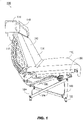
- an exemplary embodiment of a slouching divan 100 includes a supporting structure including front and rear legs 102, 104, frame rails 106 supporting a seatpan 108, a seatpan cushion 110 attachable to the seatpan, a backrest 112 connected to the frame rails, a backrest cushion 114 attachable to the backrest, a headrest 116 mounted atop the backrest (at least partially covered by a removable fixed shoulder support cushion 118), and a back follower panel 120 at least partially covering the backrest.
- the slouching divan 100 may ordinarily include a left and right set of front and rear legs 102, 104 as well as a left and right frame rail 106.
- the back follower panel 120 and the seatpan 108 may be fully or partially covered by seat cushions (e.g., respectively the backrest cushion 114 and the seatpan cushion 110) to comfortably support a passenger occupying the slouching divan 100.
- the slouching divan 100 may be configured for single-passenger, double-passenger, or triple-passenger occupancy, e.g. simultaneous use by one, two, or three passengers; for example, the seatpan 108, backrest 112, and back follower panel 120 may be extended to twice or thrice the width of a single-passenger divan.
- the slouching divan 100 may be mounted to an aircraft interior, e.g., to the floor of an aircraft, by track attachment fittings 122 configured to secure the slouching divan to tracks (not shown) set into the aircraft floor; alternatively, the slouching divan 100 may be mounted directly into the floor tracks.
- the track attachment fittings 122 may be quick-release track fittings configured to fit into the tracks without leaving loose parts when removed from the tracks, e.g., by a single shear retainer vertically adjustable and insertable into/removable from the floor track.
- the slouching divan 100 may be installable within an aircraft in either a forward-facing, aft-facing, or inboard-facing configuration.
- Inboard-facing embodiments of the slouching divan 100 may include additional safety features to detect (e.g., via accelerometers or similar crash sensors), and protect occupying passengers from, sudden lateral impact forces associated with a crash or other rapid deceleration, e.g., a leg-flail prevention device for preventing the legs and/or lower extremities of an inboard-facing passenger (whose upper body may otherwise be protected from impact forces by armrests) from flailing forward in a crash scenario.
- the leg-flail prevention device may be mounted to the frame rail 106 or to the front legs and rear legs 102, 104 on the left or right side, deploying forward in response to a detected inertial event.
- a front-facing or aft-facing slouching divan 100 may include a harness (e.g., a lap belt, shoulder belt, or lap/shoulder belt combination) including one or more airbags configured to rapidly deploy in response to a detected crash or impact force, providing additional protection for the occupying passenger/s.
- a harness e.g., a lap belt, shoulder belt, or lap/shoulder belt combination
- airbags configured to rapidly deploy in response to a detected crash or impact force, providing additional protection for the occupying passenger/s.
- the slouching divan 100 may be further stabilized by additional cross-members 124 connecting the front legs 102 and rear legs 104 on each side of the divan; the cross-members 124 may evenly distribute the interface load throughout the divan and to the floor tracks (e.g., the shifting weight of one or more occupying passengers) when the slouching divan transitions between upright, slouched, and berthed configurations.
- additional cross-members 124 connecting the front legs 102 and rear legs 104 on each side of the divan; the cross-members 124 may evenly distribute the interface load throughout the divan and to the floor tracks (e.g., the shifting weight of one or more occupying passengers) when the slouching divan transitions between upright, slouched, and berthed configurations.
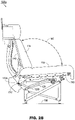
- a slouching divan 100a may be implemented and may function similarly to the slouching divan 100 of FIG. 1 , except that the slouching divan 100a may be positioned in an upright seating configuration.
- the slouching divan 100a may remain in the upright configuration during taxi, take-off and landing (TTOL) phases or flight segments, until the aircraft within which the slouching divan 100a is installed reaches a safe cruising altitude.
- the slouching divan 100a may then be transitioned to a slouching or berthed configuration (see, e.g., FIGS.
- the slouching divan 100a may include shoulder harnesses (116a) as described above, stowed within the headrests 116 and accessible (e.g., rotatable to a vertical position) via handles 116b.
- the seatpan 108 may be connected to the frame rails 106 by roller bearings 126 (or any similarly appropriate tracking members) disposed within lateral roller slots (128) machined into the frame rails.
- the lateral roller slots 128 may be incorporated (e.g., machined or set) into separate attachable components which may be mounted to the frame rails 106.
- the lateral roller slots 128 may track substantially forward (e.g., the direction in which the slouching divan 100a is oriented) towards the front end of the seatpan 108.
- the passenger may do so by articulating the seatpan 108 forward and the forward motion of the seatpan will be regulated by the lateral roller slots 128.
- the seatpan 108 may be coupled to the back follower panel 120 by a set of J-connectors 130 (or any appropriate linking members) such that forward motion of the seatpan 108 is transmitted to the back follower panel 120, which may follow the motion of the seatpan along a counterpart set of backrest roller slots 132 machined into the backrest 110.
- the backrest roller slots 132 may curve rearward, such that the distance traveled by the back follower panel 120 in its substantially downward path is slightly increased and the depth achievable by the slouching divan 100a in the berthing configuration (see, e.g., FIGS. 6A / B ) is accordingly greater than would be the case with a straight-beam backrest.
- the back follower panel 120 and seatpan 108 of the slouching divan 100a may be aligned so that in the upright configuration, the seatpan angle (134; e.g., the angle of the seatpan to the aircraft floor (136), or to the horizontal) is between three and eight degrees, e.g., 4.73 degrees as shown by FIG. 2A .
- the backrest angle (138; e.g., the angle of the back follower panel 120 to the vertical) may be between 13 and 18 degrees (e.g., 16.1 degrees, as shown by FIG. 2A ).
- the included angle 140, or the angle between the seatpan 108 and the back follower panel 120 may be between 95 and 105 degrees (e.g., 101.37 degrees, as shown by FIG. 2A ).
- the slouching divan 100a may include a seatpan cushion 110 of a substantially uniform thickness, such that when the seatpan cushion and the backrest cushion 114 are attached to the seatpan 108 and back follower panel 120 respectively, the cushion angle (142; e.g., the angle between the seatpan cushion 110 and the backrest cushion 114) is between 104 and 114 degrees (e.g., 108.92 degrees as shown by FIG. 2B ).
- the seatpan 108 may have, on its left and right sides, a seatpan rail (144) fixed to the seatpan in close proximity to the frame rails 106.
- each seatpan rail 144 may have an upright locking slot (146) set thereinto which accepts a locking pin (148) for securing the slouching divan 100a into the upright configuration.
- the seatpan roller 126, FIG. 2B
- the lateral roller slot 128 may track downward from the rear endpoint 128a to a midpoint (128b, FIG.
- the seatpan roller 126 may track forward and down from the rear endpoint 128a to the midpoint 128b and stop there, the slouched divan 100a having achieved the slouched configuration.
- the tracking of the seatpan from the rear endpoint 128a to the midpoint 128b may be rapid, and the termination of said tracking-i.e., when the seatpan roller 126 reaches the midpoint 128b-may be abrupt. From the perspective of the occupying passenger, this process may be uncomfortably jarring; for example, if the passenger is holding a glass, dish, or other container at the time, its contents may be spilled or otherwise upset.
- the slouching divan 100a may employ a damping system to regulate the rate at which the seatpan 108 tracks from the upright configuration (as shown by FIGS. 2A / B ) to the slouched configuration (as shown by FIGS. 5A / B ).
- the seatpan rail 144 may further include a set of rack teeth 150 machined along the rail.
- the frame rail 106 may include a rotary damping device 152a configured to rotate forward (e.g., toward the front of the slouching divan 100a, or in the direction in which the divan is oriented to face) at no more than a maximum rate.
- the rotary damping device 152a may include a set of damping teeth 152 around its circumference, the damping teeth proportioned so as to engage with the rack teeth 150.
- the rack teeth 150 may be located along the seatpan rail 144 such that when the slouching divan 100a is in the upright configuration (as shown by FIGS. 2A / B ), the rack teeth are immediately adjacent to the rotary damping device (e.g., toward the rear of the divan). Accordingly, when the seatpan 108 is articulated forward (108a) to transition the slouching divan 100a from the upright configuration to the slouched configuration (as shown by FIGS.
- the rack teeth 150 may immediately engage the rotary damping device (in particular, the damping teeth 152). As the rack teeth 150 proceed forward with the seatpan 108, the damping teeth 152 engage the rack teeth, rotating forward (152b) at no more than the predetermined maximum rate and preventing the seatpan 108 from moving forward any faster than the maximum rate, regulating and smoothing the transition to the slouched configuration.
- the damping teeth 152 engage the rack teeth, rotating forward (152b) at no more than the predetermined maximum rate and preventing the seatpan 108 from moving forward any faster than the maximum rate, regulating and smoothing the transition to the slouched configuration.
- the rotary damping device may be unidirectional, such that while the damping teeth 152 engage with the rack teeth 150 and thereby constrain the forward movement of the seatpan 108, the rotary damping device does not impede the rearward motion of the seatpan, e.g., while re-stowing the slouching divan from the slouched configuration to the upright configuration.
- the slouched divan 100a may include any other appropriate rotary or non-rotary means of constraining the forward movement of the seatpan 108 during transition from the upright configuration to the slouched configuration, e.g., linear plunger-type dampers or catch-fork type dampers.
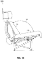
- the slouched divan 100b may be implemented and may function similarly to the slouched divan 100a of FIGS. 2A /B, except that the slouched divan 100b has fully transitioned into the slouched configuration.
- the seatpan 108 may track forward from its upright position (as shown by FIGS. 2A / B ) as the seatpan roller 126 tracks forward and downward to the midpoint 128b in the lateral roller slot 128.
- the seatpan angle 134 of the seatpan 108 relative to the aircraft floor 136)and to the horizontal may increase, e.g., the rear end of the seatpan may drop as the seatpan roller 126 tracks forward and downward to the midpoint 128b of the lateral roller slot 128.
- the left and right locking pins 148 may engage with slouch locking slots 146a positioned rearward of the upright locking slots 146, and configured for securing the slouching divan 100b in the slouched configuration.
- the back follower panel 120 connected to the seatpan 108 by J-connectors 130, may follow the seatpan by tracking downward and rearward along the backrest roller slot 132 to rest at a slightly increased angle to the seatpan 108 and the aircraft floor 136; for example, the backrest angle 138 may range from 24 to 30 degrees to the vertical (e.g., 26.89 degrees, as shown by FIG. 5A ).
- the rack teeth 150 having engaged the rotary damping device 152a, may rest fully outside the rotary damping device, such that no rack teeth remain to engage with the rotary damping device as the seatpan 108 tracks forward from the slouched configuration to the berthed configuration shown by FIGS. 6A /B.
- the included angle 140 between the seatpan 108 and the back follower panel 120 may range from 101 to 111 degrees (e.g., 106.47 degrees as shown by FIG. 5A ).
- the cushion angle 142 between the seatpan cushion 110 and the backrest cushion 114 may range from 109 to 119 degrees (e.g., 114.02 degrees, as shown by FIG. 5B ).
- the slouching divan 100c may be implemented and may function similarly to the slouching divan 100b of FIGS. 5A /B, except that the slouching divan 100c has fully transitioned from the slouched configuration shown by FIGS. 5A /B into a berthed configuration (e.g., for passengers wishing to sleep).
- the seatpan roller 126 may track forward and upward from the midpoint 128b of the lateral roller slot 128 to a forward endpoint 128c; the seatpan 108 may follow to a maximally forward position.
- the back follower panel 120 connected to the seatpan 108 by J-connectors 130, may follow the seatpan forward (tracking along the backrest roller slot 132) to a position substantially parallel to the seatpan 108 (and to a horizontal plane parallel to the aircraft floor 136, resulting in a seatpan angle 134 of substantially zero).
- the seatpan may be locked in place by left and right berth locking slots (146b) machined into the seatpan rail 144 (e.g., to the rear of the upright locking slots 146 and the slouch locking slots 146a) and configured to accommodate the left and right locking pins 148.
- the slouching divan 100c may save weight and complexity by being lockable into one of these three discrete configurations (the berthed configuration or the upright and slouched configurations shown by FIGS. 2A /B and 5A/B) rather than, e.g., an infinite number of possible configurations between the berthed configuration and the upright configuration shown by FIGS. 2A /B.
- the backrest angle 138 of the back follower panel 120 to the vertical may range from 80 to 86 degrees, e.g., 82.8 degrees as shown by FIG. 6A .
- the included angle 140 between the back follower panel 120 and the seatpan 108 may range from 167 to 177 degrees (e.g., 172.8 degrees, as shown by FIG. 6A ).
- the cross-members 124 may evenly distribute the interface load supported thereby (e.g., among the front legs 102 and rear legs 104).
- the seatpan cushion 110 may be of a uniform depth, and the depth of the backrest cushion 114 may vary from top to bottom such that when the slouching divan 100b is in the berthed configuration, the cushion angle 142 between the seatpan cushion 110 and the backrest cushion 114 is substantially 180 degrees; e.g., the surface of the backrest cushion 114 is substantially coplanar with the surface of the seatpan cushion 110, with both cushions substantially parallel to the aircraft floor (136).
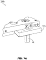
- the seatpan 108b may be implemented and may function similarly to the seatpan 108 of FIGS. 2A /B, except that the seatpan 108b may include a handle 154 for unlocking the seatpan 108b for transitioning the slouching divan 100a ( FIGS. 2A / B ) from the upright configuration shown by FIGS. 2A /B into the slouched and berthed configurations 100b-c shown by FIGS. 5A /B and 6A/B respectively.
- the handle 154 may be mounted to the forward left, or forward outboard, side of the seatpan 108b proximate to a front leg 102 and to forward support rails 156 supporting the seatpan 108b laterally between left-side and right-side front legs 102.
- the handle 154 may be partially enclosed in a housing 154a to prevent unintentional unlocking of the seatpan 108b.
- An occupying passenger may grasp the handle 154, pulling the handle forward to disengage the left and right locking pins (148, FIG. 3 ) from the particular left and right locking slots (146, 146a-b; FIG. 6B ) with which the locking pins are currently engaged (e.g., the upright locking slots 146, FIG.
- the seatpan 108b to freely track forward from the upright configuration to the slouched configuration and the berthed configuration (or, for example, tracking the seatpan rearward to re-stow a berthed slouching divan (100c, FIGS. 6A / B ) in the slouched or upright configuration.
- the locking pins 148 which engage the locking slots 146, 146a-b on the left and right sides of the slouching divan 100a-c (see FIGS.
- 2A /B, 5A/B, 6A/B may be disengaged from the locking slots 146 and re-engaged with different locking slots 146a-b by locking cables 158 controlled by the handle 154 and extending laterally underneath the seatpan 108b (e.g., proximate and parallel to the forward support rail 158) to the reverse side of the locking pins 148 on either side of the seatpan 108b.
- a slouching divan may provide for optimally comfortable transitions between upright and slouched configurations by regulating the rate of said transitions. Further, the slouching divan saves weight and complexity by being configurable and lockable in three discrete positions rather than an infinite number of possible intermediate positions.
Description
- Modem business and executive aircraft may incorporate, in addition to or instead of conventional forward-facing single-passenger seating associated with commercial aircraft, convertible seating configurations able to be reconfigured to allow the occupying passengers to sleep in a prone or near-prone position while inflight. For example, divans (e.g., sofas, couches, settees) may accommodate one or more passengers in a forward-facing, aft-facing, or inboard-facing orientation. Such an aircraft divan may be configured for compliance with any applicable seating regulations, e.g., equipped with seatbelts or harnesses to restrain the occupying passengers in an upright position during taxi, takeoff, and landing (TToL) phases or flight segments. Once the aircraft is inflight and a safe cruising altitude is achieved, the passenger/s may reposition or reconfigure the divan from an upright seated position (e.g., where the seatpan of the divan is substantially parallel to the aircraft floor and the backrest of the divan is substantially perpendicular, or at a slightly obtuse angle, thereto) to a fully extended, or berthed, position wherein the seatpan and backrest of the divan are substantially coplanar with each other and substantially parallel to the aircraft floor.
- United States patent application
US 2017/021930 A1 discloses a cradle recline mechanism for an aircraft passenger seat including a guide mechanism for guiding a seat bottom of the aircraft passenger seat forward and lower as the seat bottom moves from an upright sitting position to a cradle recline sitting position, where a rear portion of the seat bottom is lowered more than a front portion of the seat bottom, causing the seat bottom to angle upwards from a bottom edge of the seat back. A seat back of the passenger seat may be pivotably connected to the seat bottom such that it is pulled forward and down with the movement of the seat bottom, with the recline angle determined by a rigid support mechanism disposed behind the seat back. Passenger weight may be counterbalanced using a moveable control mechanism such as a locking gas spring. - European
patent application EP 0 869 060 A1 discloses a seat for an aircraft having an open outer shell which embraces a seat portion, a seat back, a headrest and a footrest when the seat is in an upright position. The seat is reclinable into a bed configuration such that the seat portion is moved forwardly out of the open end of the shell. - United States patent application
US 2007/262625 A1 discloses a seating unit for an aircraft cabin and comprising a fixed housing containing a primary seat with a reclinable back arranged to recline in such a manner that it remains within the housing. The seat comprises a leg-rest arranged to cooperate with the seating portion to form part of a substantially flat surface when the back is reclined in a substantially horizontal position. The seating unit comprises a secondary seat having a seating portion positioned to cooperate with the leg-rest of the primary seat to form a portion of the substantially flat surface when the back of the primary seat is reclined in the substantially horizontal position. - An occupying passenger may additionally reposition the divan to one or more intermediate reclining or "slouching" positions between the upright position and the berthed position. For example, a slouched position may be characterized by a seatpan at a slightly acute angle to the aircraft floor (e.g., wherein the rear end of the seatpan has dropped from its upright position, the front end of the seatpan has remained in its upright position, and the angle of the backrest to the aircraft floor has slightly increased). However, for the divan to be capable of multiple, or infinite, intermediate positions between the upright and berthed positions may require complex and heavy locking and articulation equipment for securing the divan in the desired intermediate position. Further, the divan may be configured for transition from the upright to the slouched position at least partially assisted by gravity and/or the weight of the occupying passenger. As a result, the transition from the upright to the slouched position, which may involve tracking the rear end of the seatpan along a downward path, may be uncomfortably rapid for the occupying passenger; similarly, achieving the slouched position may result in an abrupt jolt for the occupying passenger.
- In one aspect, embodiments of the inventive concepts disclosed herein are directed to a slouching divan (e.g., couch) installable aboard an aircraft. The divan may be of single-, double-, or triple-passenger size and transitionable between three discrete configurations-upright/seated, slouched (e.g., reclined), and berthed (e.g., fully extended for sleeping)-and may regulate the transition between configurations via motion dampers. The divan is mountable to the aircraft floor (e.g., forward-facing, aft-facing, or inboard-facing) via front and rear legs. The front and rear legs are connected by frame rails, the frame rails including lateral slots extending from a rear end downward to a midpoint, and then up from the midpoint toward a front end. A seatpan (upon which a seatpan cushion may provide additional comfort for occupying passengers) may incorporate rollers traveling within the lateral slots. For example, when the rollers are at the rear end, midpoint, or front end respectively, the divan may be in the upright, slouched, or berthed configuration. The seatpan may include seatpan rails at the right and left sides. The divan has a backrest also including roller slots extending from the top of the backrest down to the bottom in a path that curves to the rear. The divan includes a back follower panel (to which a backrest cushion may be attached) connected to the seatpan and connected to the backrest by rollers or bearings. For example, the back follower panel follows the seatpan as it tracks forward along the lateral slots; the curvature in the backrest roller slots allows the back follower panel to track forward far enough that the backrest and seatpan cushions provide a flat surface (e.g., parallel to the floor) for the occupying passengers to rest upon. Because the seatpan rollers travel downward (e.g., assisted by gravity) when transitioning from the upright to the slouched configuration, the divan may incorporate one-way damping devices to regulate the speed with which the seatpan rollers track forward and downward, and the suddenness with which the rollers stop tracking when the midpoint of the lateral slots is reached and the divan achieves the slouched configuration. The damping devices are one-way in that they do not interfere with the stowing of the divan from the slouched configuration back to the upright configuration (e.g., for taxi, takeoff and landing procedures).
- Implementations of the inventive concepts disclosed herein may be better understood when consideration is given to the following detailed description thereof. Such description makes reference to the included drawings, which are not necessarily to scale, and in which some features may be exaggerated and some features may be omitted or may be represented schematically in the interest of clarity. Like reference numerals in the drawings may represent and refer to the same or similar element, feature, or function. In the drawings:
-
FIG. 1 is a perspective view of an exemplary embodiment of a slouching divan according to the inventive concepts disclosed herein; -
FIGS. 2A and2B illustrate a right profile view of the slouching divan ofFIG. 1 in an upright seating configuration; -
FIG. 3 is a closeup right profile view of a locking mechanism of the slouching divan ofFIGS. 2A and2B ; -
FIG. 4 is a closeup right profile view of a damping device of the slouching divan ofFIGS. 2A and2B ; -
FIGS. 5A and5B illustrate a right profile view of the slouching divan ofFIG. 1 in a slouched configuration; -
FIGS. 6A and6B is a right profile view of the slouching divan ofFIG. 1 in a berthed configuration; -
FIG. 7A is a forward perspective view of the mechanical controls of the seatpan ofFIGS. 2A and2B ; and -
FIGS. 7B and7C are underside views of the mechanical controls and pin-lock housing of the seatpan ofFIG. 7A . - Before explaining at least one embodiment of the inventive concepts disclosed herein in detail, it is to be understood that the inventive concepts are not limited in their application to the details of construction and the arrangement of the components or steps or methodologies set forth in the following description or illustrated in the drawings. The current invention is limited only by the appended
claim 1. In the following detailed description of embodiments of the instant inventive concepts, numerous specific details are set forth in order to provide a more thorough understanding of the inventive concepts defined in the claims. However, it will be apparent to one of ordinary skill in the art having the benefit of the instant disclosure that the inventive concepts disclosed herein may be practiced without these specific details. In other instances, well-known features may not be described in detail to avoid unnecessarily complicating the instant disclosure. The inventive concepts disclosed herein are capable of other embodiments or of being practiced or carried out in various ways. Also, it is to be understood that the phraseology and terminology employed herein is for the purpose of description and should not be regarded as limiting. - As used herein a letter following a reference numeral is intended to reference an embodiment of the feature or element that may be similar, but not necessarily identical, to a previously described element or feature bearing the same reference numeral (e.g., 1, 1a, 1b). Such shorthand notations are used for purposes of convenience only, and should not be construed to limit the inventive concepts disclosed herein in any way unless expressly stated to the contrary.
- Further, unless expressly stated to the contrary, "or" refers to an inclusive or and not to an exclusive or. For example, a condition A or B is satisfied by anyone of the following: A is true (or present) and B is false (or not present), A is false (or not present) and B is true (or present), and both A and B are true (or present).
- In addition, use of the "a" or "an" are employed to describe elements and components of embodiments of the instant inventive concepts. This is done merely for convenience and to give a general sense of the inventive concepts, and "a' and "an" are intended to include one or at least one and the singular also includes the plural unless it is obvious that it is meant otherwise.
- Finally, as used herein any reference to "one embodiment," or "some embodiments" means that a particular element, feature, structure, or characteristic described in connection with the embodiment is included in at least one embodiment of the inventive concepts disclosed herein. The appearances of the phrase "in some embodiments" in various places in the specification are not necessarily all referring to the same embodiment, and embodiments of the inventive concepts disclosed may include one or more of the features expressly described or inherently present herein, or any combination of sub-combination of two or more such features, along with any other features which may not necessarily be expressly described or inherently present in the instant disclosure.
- Broadly, embodiments of the inventive concepts disclosed herein are directed to a slouching aircraft divan with damped motion. The divan is convertible by an occupying passenger between an upright seated configuration into a reclined or "slouched" configuration and a sleeping or "berthed" configuration. Damping devices prevent the transition from the seated to slouched configuration from becoming sudden or jarring without otherwise interfering with the conversion process in either direction. The divan may save weight and complexity by easily locking into one of the above three configurations as opposed to an infinite number of intermediate positions.
- Referring to
FIG. 1 , an exemplary embodiment of a slouchingdivan 100 according to the inventive concepts disclosed herein includes a supporting structure including front andrear legs seatpan 108, aseatpan cushion 110 attachable to the seatpan, abackrest 112 connected to the frame rails, abackrest cushion 114 attachable to the backrest, aheadrest 116 mounted atop the backrest (at least partially covered by a removable fixed shoulder support cushion 118), and aback follower panel 120 at least partially covering the backrest. The slouchingdivan 100 may ordinarily include a left and right set of front andrear legs right frame rail 106. Theback follower panel 120 and theseatpan 108 may be fully or partially covered by seat cushions (e.g., respectively thebackrest cushion 114 and the seatpan cushion 110) to comfortably support a passenger occupying the slouchingdivan 100. The slouchingdivan 100 may be configured for single-passenger, double-passenger, or triple-passenger occupancy, e.g. simultaneous use by one, two, or three passengers; for example, theseatpan 108,backrest 112, and backfollower panel 120 may be extended to twice or thrice the width of a single-passenger divan. The slouchingdivan 100 may be mounted to an aircraft interior, e.g., to the floor of an aircraft, bytrack attachment fittings 122 configured to secure the slouching divan to tracks (not shown) set into the aircraft floor; alternatively, the slouchingdivan 100 may be mounted directly into the floor tracks. Thetrack attachment fittings 122 may be quick-release track fittings configured to fit into the tracks without leaving loose parts when removed from the tracks, e.g., by a single shear retainer vertically adjustable and insertable into/removable from the floor track. The slouchingdivan 100 may be installable within an aircraft in either a forward-facing, aft-facing, or inboard-facing configuration. Inboard-facing embodiments of the slouchingdivan 100 may include additional safety features to detect (e.g., via accelerometers or similar crash sensors), and protect occupying passengers from, sudden lateral impact forces associated with a crash or other rapid deceleration, e.g., a leg-flail prevention device for preventing the legs and/or lower extremities of an inboard-facing passenger (whose upper body may otherwise be protected from impact forces by armrests) from flailing forward in a crash scenario. For example, the leg-flail prevention device may be mounted to theframe rail 106 or to the front legs andrear legs slouching divan 100 may include a harness (e.g., a lap belt, shoulder belt, or lap/shoulder belt combination) including one or more airbags configured to rapidly deploy in response to a detected crash or impact force, providing additional protection for the occupying passenger/s. The slouchingdivan 100 may be further stabilized byadditional cross-members 124 connecting thefront legs 102 andrear legs 104 on each side of the divan; the cross-members 124 may evenly distribute the interface load throughout the divan and to the floor tracks (e.g., the shifting weight of one or more occupying passengers) when the slouching divan transitions between upright, slouched, and berthed configurations. - Referring now to
FIGS. 2A and2B , a slouchingdivan 100a may be implemented and may function similarly to the slouchingdivan 100 ofFIG. 1 , except that the slouchingdivan 100a may be positioned in an upright seating configuration. For example, the slouchingdivan 100a may remain in the upright configuration during taxi, take-off and landing (TTOL) phases or flight segments, until the aircraft within which the slouchingdivan 100a is installed reaches a safe cruising altitude. The slouchingdivan 100a may then be transitioned to a slouching or berthed configuration (see, e.g.,FIGS. 3 and4 ) by passengers wishing a more accommodating resting or sleeping position, and re-stowed to the upright configuration upon initial descent. The slouchingdivan 100a may include shoulder harnesses (116a) as described above, stowed within theheadrests 116 and accessible (e.g., rotatable to a vertical position) viahandles 116b. - The
seatpan 108 may be connected to the frame rails 106 by roller bearings 126 (or any similarly appropriate tracking members) disposed within lateral roller slots (128) machined into the frame rails. Alternatively, thelateral roller slots 128 may be incorporated (e.g., machined or set) into separate attachable components which may be mounted to the frame rails 106. Thelateral roller slots 128 may track substantially forward (e.g., the direction in which the slouchingdivan 100a is oriented) towards the front end of theseatpan 108. For example, if an occupying passenger wishes to transition the slouchingdivan 100a into the slouched or berthed configuration, the passenger may do so by articulating theseatpan 108 forward and the forward motion of the seatpan will be regulated by thelateral roller slots 128. Theseatpan 108 may be coupled to theback follower panel 120 by a set of J-connectors 130 (or any appropriate linking members) such that forward motion of theseatpan 108 is transmitted to theback follower panel 120, which may follow the motion of the seatpan along a counterpart set ofbackrest roller slots 132 machined into thebackrest 110. Thebackrest roller slots 132 may curve rearward, such that the distance traveled by theback follower panel 120 in its substantially downward path is slightly increased and the depth achievable by the slouchingdivan 100a in the berthing configuration (see, e.g.,FIGS. 6A /B ) is accordingly greater than would be the case with a straight-beam backrest. - The
back follower panel 120 and seatpan 108 of the slouchingdivan 100a may be aligned so that in the upright configuration, the seatpan angle (134; e.g., the angle of the seatpan to the aircraft floor (136), or to the horizontal) is between three and eight degrees, e.g., 4.73 degrees as shown byFIG. 2A . Similarly, the backrest angle (138; e.g., the angle of theback follower panel 120 to the vertical) may be between 13 and 18 degrees (e.g., 16.1 degrees, as shown byFIG. 2A ). Accordingly, the includedangle 140, or the angle between the seatpan 108 and theback follower panel 120, may be between 95 and 105 degrees (e.g., 101.37 degrees, as shown byFIG. 2A ). - Referring in particular to
FIG. 2B , the slouchingdivan 100a may include aseatpan cushion 110 of a substantially uniform thickness, such that when the seatpan cushion and thebackrest cushion 114 are attached to theseatpan 108 and backfollower panel 120 respectively, the cushion angle (142; e.g., the angle between theseatpan cushion 110 and the backrest cushion 114) is between 104 and 114 degrees (e.g., 108.92 degrees as shown byFIG. 2B ). - The
seatpan 108 may have, on its left and right sides, a seatpan rail (144) fixed to the seatpan in close proximity to the frame rails 106. Referring also toFIG. 3 , eachseatpan rail 144 may have an upright locking slot (146) set thereinto which accepts a locking pin (148) for securing the slouchingdivan 100a into the upright configuration. When the slouchingdivan 100a is in the upright configuration, the seatpan roller (126,FIG. 2B ) may be disposed at a rear endpoint (128a,FIG. 2B ) of the lateral roller slots (128,FIG. 2B ). Thelateral roller slot 128 may track downward from therear endpoint 128a to a midpoint (128b,FIG. 2B ). When the slouchingdivan 100a is transitioned into the slouching configuration (as shown byFIGS. 5A /B; e.g., by articulation of theseatpan 108 by the occupying passenger after "unlocking" the divan by releasing the left and right locking pins 148 from the upright locking slots 146), theseatpan roller 126 may track forward and down from therear endpoint 128a to themidpoint 128b and stop there, the sloucheddivan 100a having achieved the slouched configuration. If the forward- and-down tracking of theseatpan 108 is assisted by gravity and the weight of the occupying passenger, the tracking of the seatpan from therear endpoint 128a to themidpoint 128b may be rapid, and the termination of said tracking-i.e., when theseatpan roller 126 reaches themidpoint 128b-may be abrupt. From the perspective of the occupying passenger, this process may be uncomfortably jarring; for example, if the passenger is holding a glass, dish, or other container at the time, its contents may be spilled or otherwise upset. - Accordingly, the slouching
divan 100a may employ a damping system to regulate the rate at which the seatpan 108 tracks from the upright configuration (as shown byFIGS. 2A /B ) to the slouched configuration (as shown byFIGS. 5A /B ). For example, referring also toFIG. 4 , theseatpan rail 144 may further include a set ofrack teeth 150 machined along the rail. Theframe rail 106 may include a rotary dampingdevice 152a configured to rotate forward (e.g., toward the front of the slouchingdivan 100a, or in the direction in which the divan is oriented to face) at no more than a maximum rate. For example, therotary damping device 152a may include a set of dampingteeth 152 around its circumference, the damping teeth proportioned so as to engage with therack teeth 150. Therack teeth 150 may be located along theseatpan rail 144 such that when the slouchingdivan 100a is in the upright configuration (as shown byFIGS. 2A /B ), the rack teeth are immediately adjacent to the rotary damping device (e.g., toward the rear of the divan). Accordingly, when theseatpan 108 is articulated forward (108a) to transition the slouchingdivan 100a from the upright configuration to the slouched configuration (as shown byFIGS. 5A /B ), therack teeth 150 may immediately engage the rotary damping device (in particular, the damping teeth 152). As therack teeth 150 proceed forward with theseatpan 108, the dampingteeth 152 engage the rack teeth, rotating forward (152b) at no more than the predetermined maximum rate and preventing the seatpan 108 from moving forward any faster than the maximum rate, regulating and smoothing the transition to the slouched configuration. The rotary damping device may be unidirectional, such that while the dampingteeth 152 engage with therack teeth 150 and thereby constrain the forward movement of theseatpan 108, the rotary damping device does not impede the rearward motion of the seatpan, e.g., while re-stowing the slouching divan from the slouched configuration to the upright configuration. The sloucheddivan 100a may include any other appropriate rotary or non-rotary means of constraining the forward movement of the seatpan 108 during transition from the upright configuration to the slouched configuration, e.g., linear plunger-type dampers or catch-fork type dampers. - Referring to
FIGS. 5A and5B , the sloucheddivan 100b may be implemented and may function similarly to the sloucheddivan 100a ofFIGS. 2A /B, except that the sloucheddivan 100b has fully transitioned into the slouched configuration. For example, theseatpan 108 may track forward from its upright position (as shown byFIGS. 2A /B ) as theseatpan roller 126 tracks forward and downward to themidpoint 128b in thelateral roller slot 128. As a result, theseatpan angle 134 of theseatpan 108 relative to the aircraft floor 136)and to the horizontal may increase, e.g., the rear end of the seatpan may drop as theseatpan roller 126 tracks forward and downward to themidpoint 128b of thelateral roller slot 128. The left and right locking pins 148 may engage withslouch locking slots 146a positioned rearward of theupright locking slots 146, and configured for securing the slouchingdivan 100b in the slouched configuration. In addition, theback follower panel 120, connected to theseatpan 108 by J-connectors 130, may follow the seatpan by tracking downward and rearward along thebackrest roller slot 132 to rest at a slightly increased angle to theseatpan 108 and theaircraft floor 136; for example, thebackrest angle 138 may range from 24 to 30 degrees to the vertical (e.g., 26.89 degrees, as shown byFIG. 5A ). Finally, therack teeth 150, having engaged the rotary dampingdevice 152a, may rest fully outside the rotary damping device, such that no rack teeth remain to engage with the rotary damping device as the seatpan 108 tracks forward from the slouched configuration to the berthed configuration shown byFIGS. 6A /B. - When the slouching
divan 100b is in the slouched configuration, the includedangle 140 between the seatpan 108 and theback follower panel 120 may range from 101 to 111 degrees (e.g., 106.47 degrees as shown byFIG. 5A ). Referring also toFIG. 5B , thecushion angle 142 between theseatpan cushion 110 and thebackrest cushion 114 may range from 109 to 119 degrees (e.g., 114.02 degrees, as shown byFIG. 5B ). - Referring now to
FIGS. 6A and6B , the slouchingdivan 100c may be implemented and may function similarly to the slouchingdivan 100b ofFIGS. 5A /B, except that the slouchingdivan 100c has fully transitioned from the slouched configuration shown byFIGS. 5A /B into a berthed configuration (e.g., for passengers wishing to sleep). For example, theseatpan roller 126 may track forward and upward from themidpoint 128b of thelateral roller slot 128 to aforward endpoint 128c; theseatpan 108 may follow to a maximally forward position. Theback follower panel 120, connected to theseatpan 108 by J-connectors 130, may follow the seatpan forward (tracking along the backrest roller slot 132) to a position substantially parallel to the seatpan 108 (and to a horizontal plane parallel to theaircraft floor 136, resulting in aseatpan angle 134 of substantially zero). Once theseatpan 108 has tracked forward to its berthed position, the seatpan may be locked in place by left and right berth locking slots (146b) machined into the seatpan rail 144 (e.g., to the rear of theupright locking slots 146 and theslouch locking slots 146a) and configured to accommodate the left and right locking pins 148. The slouchingdivan 100c may save weight and complexity by being lockable into one of these three discrete configurations (the berthed configuration or the upright and slouched configurations shown byFIGS. 2A /B and 5A/B) rather than, e.g., an infinite number of possible configurations between the berthed configuration and the upright configuration shown byFIGS. 2A /B. When the slouchingdivan 100b is in the berthed configuration, thebackrest angle 138 of theback follower panel 120 to the vertical may range from 80 to 86 degrees, e.g., 82.8 degrees as shown byFIG. 6A . Similarly, the includedangle 140 between theback follower panel 120 and theseatpan 108 may range from 167 to 177 degrees (e.g., 172.8 degrees, as shown byFIG. 6A ). - Referring also to
FIG. 6B , as the seatpan 108 tracks forward, the cross-members 124 may evenly distribute the interface load supported thereby (e.g., among thefront legs 102 and rear legs 104). Theseatpan cushion 110 may be of a uniform depth, and the depth of thebackrest cushion 114 may vary from top to bottom such that when the slouchingdivan 100b is in the berthed configuration, thecushion angle 142 between theseatpan cushion 110 and thebackrest cushion 114 is substantially 180 degrees; e.g., the surface of thebackrest cushion 114 is substantially coplanar with the surface of theseatpan cushion 110, with both cushions substantially parallel to the aircraft floor (136). - Referring to
FIGS. 7A through 7C , the seatpan 108b may be implemented and may function similarly to theseatpan 108 ofFIGS. 2A /B, except that the seatpan 108b may include ahandle 154 for unlocking the seatpan 108b for transitioning the slouchingdivan 100a (FIGS. 2A /B ) from the upright configuration shown byFIGS. 2A /B into the slouched and berthedconfigurations 100b-c shown byFIGS. 5A /B and 6A/B respectively. For example, thehandle 154 may be mounted to the forward left, or forward outboard, side of the seatpan 108b proximate to afront leg 102 and to forward support rails 156 supporting the seatpan 108b laterally between left-side and right-sidefront legs 102. Thehandle 154 may be partially enclosed in ahousing 154a to prevent unintentional unlocking of the seatpan 108b. An occupying passenger may grasp thehandle 154, pulling the handle forward to disengage the left and right locking pins (148,FIG. 3 ) from the particular left and right locking slots (146, 146a-b;FIG. 6B ) with which the locking pins are currently engaged (e.g., theupright locking slots 146,FIG. 3 ) and allowing the seatpan 108b to freely track forward from the upright configuration to the slouched configuration and the berthed configuration (or, for example, tracking the seatpan rearward to re-stow a berthed slouching divan (100c,FIGS. 6A /B ) in the slouched or upright configuration. For example, referring in particular to the underside of the seatpan 108b as shown byFIG. 7C the locking pins 148, which engage the lockingslots divan 100a-c (seeFIGS. 2A /B, 5A/B, 6A/B), may be disengaged from the lockingslots 146 and re-engaged withdifferent locking slots 146a-b by lockingcables 158 controlled by thehandle 154 and extending laterally underneath theseatpan 108b (e.g., proximate and parallel to the forward support rail 158) to the reverse side of the locking pins 148 on either side of the seatpan 108b. - As will be appreciated from the above, a slouching divan according to embodiments of the inventive concepts disclosed herein may provide for optimally comfortable transitions between upright and slouched configurations by regulating the rate of said transitions. Further, the slouching divan saves weight and complexity by being configurable and lockable in three discrete positions rather than an infinite number of possible intermediate positions.
- From the above description, it is clear that the inventive concepts disclosed herein are well adapted to carry out the objects and to attain the advantages mentioned herein as well as those inherent in the inventive concepts disclosed herein.
Claims (15)
- A slouching divan (100) with damped motion, comprising:at least one front leg (102) and at least one rear leg (104), the front leg (102), and the rear leg (104) mountable to a floor of an aircraft 136);at least one frame rail (106), including at least one lateral roller slot (128) extending in a downward slope from a rear endpoint (128a) associated with an upright configuration to a midpoint (128b) associated with a slouched configuration, and extending in an upward slope from the midpoint (128b) to a front endpoint (128c) associated with a berthed configuration;at least one seatpan (108) having a front end and a rear end, the seatpan (108) slidably connectable to the lateral roller slot (128), the seatpan (108) at least partially coverable by a seatpan cushion;at least one seatpan rail (144) coupled to the seatpan (108) proximate to the lateral roller slot (128);at least one backrest (112) having a top, a bottom, and at least one back roller slot (132) extending in a curving path;at least one back follower panel (120) slidably connectable to the back roller slot (132) and coupled to the seatpan (108) proximate the bottom and the rear end by at least one connector (130), such that the back follower panel (120) follows the movement of the seatpan (108) along the lateral roller slot (128), the back follower panel (120) at least partially coverable by a backrest cushion (114);andat least one unidirectional damping device (152a) coupled to the frame rail (106), the damping device (152a) configured to constrain the movement of the seatpan (108) from the upright configuration to the slouched configuration by engaging with the seatpan rail (144),characterized in thatthe least one frame rail (106) connects the front leg (102) and the rear leg (104);the at least one back roller slot (132) extends from the top to the bottom of the backrest; and in thatthe at least one back roller slot (132) extends in a rearward curving path.
- The slouching divan (100) according to claim 1, wherein:the at least one front leg (102) includes a left front leg and a right front leg;the at least one rear leg (104) includes a left rear leg and a right rear leg; and/orthe slouching divan (100) includes one of a single-passenger divan, a double-passenger divan, and a triple-passenger divan.
- The slouching divan (100) according to claim 1 or 2, further comprising:at least one cross member (124) connecting the left leg and the right leg below the seatpan (108) in a spaced apart relationship.
- The slouching divan (100) according to one or more of claims 1-3, wherein:the at least one seatpan rail (144) includes a plurality of rack teeth (150) set thereinto;
andthe at least one damping device (152a) includes a rotary damping device (152a) having a plurality of circumferential evenly spaced teeth (152) similarly sized and spaced to the plurality of rack teeth (150), the rotary damping device (152a) configured to constrain the movement of the seatpan (108) by engaging the plurality of rack teeth (150). - The slouching divan (100) according to one or more of claims 1-4, wherein:the at least one lateral roller slot (128) includes at least one of a) a first lateral roller slot (128) machined into the frame rail (106) and b) a second lateral roller slot (128) incorporated into a lateral component attachable to the frame rail (106); andthe at least one back roller slot (132) includes at least one of a) a first back roller slot (132) machined into the backrest (112) and b) a second back roller slot (132) incorporated into a lateral component attachable to the backrest (112).
- The slouching divan according (100) to one or more of claims 1-5, wherein:the at least one seatpan rail (144) includes a left seatpan rail and a right seatpan rail, the left seatpan rail comprising at least one left locking slot (146) configured to accommodate a left locking pin (148) and the right seatpan rail comprising at least one right locking slot (146) configured to accommodate a right locking pin (148);the upright configuration associated with a first left locking slot (146) and a first right locking slot (146);the slouched configuration associated with a second left locking slot (146a) and a second right locking slot (146b);andthe berthed configuration associated with a third left locking slot (146b) and a third right locking slot (146b).
- The slouching divan according (100) to claim 6, further comprising:
at least one handle (154) coupled to the front end and configured to disengage the at least one of the left locking pin (148) and the right locking pin (148) from the at least one left locking slot (146) and the at least one right locking slot (146). - The slouching divan (100) according to one or more of claims 1-7, wherein the divan (100) is mounted to the interior fixture via the at least one front leg (102) and the at least one rear leg (104) in one of a forward-facing orientation, an aft-facing orientation, and an inboard-facing orientation.
- The slouching divan (100) according to one or more of claims 1-8, wherein the floor (136) includes at least one track set thereinto, the at least one front leg (102) and the at least one rear leg (104) mountable to the at least one track wherein the at least one front leg (102) and the at least one rear leg (104) preferably are mountable to the at least one track via at least one track fitting (122) removably attachable to the track.
- The slouching divan according (100) to one or more of claims 1-9 wherein:
the seatpan (108) is slidably connectable to the lateral roller slot (128) by at least one seatpan roller (126) capable of lateral tracking within the lateral roller slot (128), and/or wherein:
the back follower panel (120) is slidably connected to the back roller slot (132) by at least one backrest roller capable of vertical tracking within the back roller slot (132). - The slouching divan (100) according to one or more of claims 1-10, further comprising:at least one crash sensor configured to detect an inertial event associated with the aircraft;andat least one enhanced restraint coupled to the crash sensor and configured to deploy in response to the detected inertial event.
- The slouching divan of claim 11, wherein the at least one enhanced restraint includes at least one harness (116a) configured to secure a passenger in the divan (100), the harness (116a) comprising:a first strap coupled to the seatpan (108) and configured to fasten around a waist of the passenger;anda second strap coupled to the backrest and configured to rest proximate to a shoulder of the passenger;at least one of the first strap and the second strap including the crash sensor;wherein preferably at least one of the first strap and the second strap includes an airbag coupled to the crash sensor and configured to inflate in response to the detected inertial event.
- The slouching divan (100) according to one or more of claims 11-12, wherein the divan (100) is associated with an inboard-facing orientation, and the enhanced restraint includes:
at least one leg flail prevention device coupled to the crash sensor and attached to one or more of the front leg (102), the rear leg (104), and the frame rail (106). - The slouching divan (100) according to one or more of claims 1-13, wherein the upright configuration is defined by:a seatpan angle (134) between the seatpan (108) and the floor (136) of between 3 and 8 degrees;a backrest angle (138) between the back follower panel (120) and a vertical of between 13 and 18 degrees;an included angle (140) between the back follower panel (120) and the seatpan (109) of between 95 and 105 degrees;anda cushion angle (142) between the backrest cushion (114) and the seatpan cushion (110) of between 104 and 114 degrees.
- The slouching divan (100) according to claim 14, wherein the slouched configuration is defined by:the seatpan angle (134) of between 8 and 14 degrees;the backrest angle (138) of between 24 and 29 degrees;the included angle (140) of between 101 and 111 degrees;andthe cushion angle (142) of between 109 and 119 degrees, and/or wherein the berthed configuration is defined by:the seatpan angle (134) of zero degrees;the backrest angle (138) of between 80 and 86 degrees;the included angle (140) of between 167 and 177 degrees;andthe cushion angle (142) of 180 degrees.
Applications Claiming Priority (2)
| Application Number | Priority Date | Filing Date | Title |
|---|---|---|---|
| US201762580925P | 2017-11-02 | 2017-11-02 | |
| US15/950,079 US10427793B2 (en) | 2017-11-02 | 2018-04-10 | Slouching divan with damped motion |
Publications (2)
| Publication Number | Publication Date |
|---|---|
| EP3480111A1 EP3480111A1 (en) | 2019-05-08 |
| EP3480111B1 true EP3480111B1 (en) | 2022-06-22 |
Family
ID=64109778
Family Applications (1)
| Application Number | Title | Priority Date | Filing Date |
|---|---|---|---|
| EP18203970.1A Active EP3480111B1 (en) | 2017-11-02 | 2018-11-01 | Slouching divan with damped motion |
Country Status (3)
| Country | Link |
|---|---|
| US (1) | US10427793B2 (en) |
| EP (1) | EP3480111B1 (en) |
| CN (1) | CN109747844A (en) |
Families Citing this family (4)
| Publication number | Priority date | Publication date | Assignee | Title |
|---|---|---|---|---|
| US11021255B2 (en) * | 2018-01-30 | 2021-06-01 | Rockwell Collins, Inc. | Work-and-dine aircraft seat with tilt and shift articulation |
| US11059589B2 (en) * | 2018-08-03 | 2021-07-13 | B/E Aerospace, Inc. | Three-place berthing aircraft divan |
| DE102019204488B4 (en) * | 2019-03-29 | 2023-05-04 | Adient Aerospace, Llc | Seat, in particular aircraft seat |
| EP4306412A1 (en) * | 2022-07-12 | 2024-01-17 | B/E Aerospace, Inc. | Self supporting berthing platform system for aircraft seats |
Family Cites Families (47)
| Publication number | Priority date | Publication date | Assignee | Title |
|---|---|---|---|---|
| FR1596508A (en) * | 1968-07-18 | 1970-06-22 | ||
| ATE62389T1 (en) * | 1987-08-14 | 1991-04-15 | Grammer Ag | SEAT, IN PARTICULAR WORK SEAT, E.G. OFFICE CHAIR OR DRIVER'S SEAT. |
| US5261725A (en) * | 1991-11-27 | 1993-11-16 | Lawrence Rudolph | Low-profile positioning apparatus |
| GB9425078D0 (en) | 1994-12-13 | 1995-02-08 | British Airways Plc | A seating unit |
| EP0723890B1 (en) * | 1995-01-27 | 2001-08-29 | Britax Aircraft Interiors UK Limited | Passenger seat |
| US6022076A (en) * | 1996-04-18 | 2000-02-08 | Samson; Ilan | Reclinable seating |
| GB9617706D0 (en) * | 1996-08-22 | 1996-10-02 | Britax Rumbold Ltd | Vehicle seat |
| SG54502A1 (en) * | 1997-02-20 | 1998-11-16 | Singapore Airlines Ltd | Improvements in transport accommodation |
| US20010000639A1 (en) * | 1997-02-20 | 2001-05-03 | Singapore Airlines Ltd. | Transport accommodation |
| NO312491B1 (en) * | 1997-02-28 | 2002-05-21 | Kjartan Alvestad | Adjusting device for the support frame in reclining or seating furniture |
| GB9706650D0 (en) * | 1997-04-02 | 1997-05-21 | Virgin Atlantic Airways Ltd | A seat |
| JPH11278115A (en) * | 1998-03-30 | 1999-10-12 | Ikeda Bussan Co Ltd | Seat for vehicle |
| DE19906547B4 (en) | 1999-02-17 | 2004-03-25 | Innovint Einrichtungs Gmbh | Child seat for mobile use in an aircraft |
| IT1306152B1 (en) * | 1999-06-02 | 2001-05-30 | Aviointeriors Spa | ARMCHAIR WITH PERFECTED CRADLE MOVEMENT, IN PARTICULAR AIRCRAFT. |
| US6305644B1 (en) * | 1999-11-10 | 2001-10-23 | B E Aerospace, Inc. | Aircraft cabin seat configuration with enhanced ingress/egress |
| US6352309B1 (en) * | 2000-01-13 | 2002-03-05 | Be Aerospace, Inc. | Passenger sleeper seat |
| EP1116652B1 (en) * | 2000-01-14 | 2006-03-15 | Be Aerospace, Inc. | Passenger seat with variable length seat bottom |
| FR2818595B1 (en) * | 2000-12-26 | 2003-03-07 | Eads Sogerma | BED CONVERTIBLE ARMCHAIR, ESPECIALLY FOR AIRCRAFT |
| US6742840B2 (en) * | 2001-05-25 | 2004-06-01 | Weber Aircraft Lp | Adjustable seats |
| US6692069B2 (en) | 2001-07-20 | 2004-02-17 | B E Aerospace, Inc. | Aircraft sleeper seat |
| ATE529293T1 (en) * | 2001-08-09 | 2011-11-15 | Virgin Atlantic Airways Ltd | A SEATING ARRANGEMENT AND A PASSENGER SEAT UNIT FOR AN AIRCRAFT |
| FR2838085B1 (en) * | 2002-04-08 | 2004-07-16 | Sicma Aero Seat | SEAT WITH MECHANICAL SYNCHRONIZATION OF THE LEG BACK AND REST |
| US6698836B1 (en) * | 2002-08-26 | 2004-03-02 | Aviointeriors S.P.A. | Mechanism to obtain the complete reclining of a seat, particularly for an aircraft seat |
| DE602004023491D1 (en) | 2004-06-29 | 2009-11-19 | Ford Global Tech Llc | Vehicle seat assembly |
| GB2433433A (en) | 2005-12-23 | 2007-06-27 | British Airways Plc | Aircraft passenger seat with secondary support surface |
| GB0704546D0 (en) * | 2007-03-08 | 2007-04-18 | Contour Premium Aircraft Seati | Adjustable seat |
| GB0706775D0 (en) * | 2007-04-05 | 2007-05-16 | Premium Aircraft Interiors Uk | Aircraft seat |
| EP2313316B1 (en) * | 2008-08-05 | 2012-05-09 | BE Aerospace, Inc. | Seat articulation mechanism |
| US8376458B2 (en) * | 2009-11-02 | 2013-02-19 | B/E Aerospace, Inc. | Seat pan cam follower with drop down mechanism |
| CN102666192B (en) * | 2009-12-25 | 2014-11-12 | 本田技研工业株式会社 | Seat device |
| US8439435B2 (en) * | 2010-02-10 | 2013-05-14 | Zodiac Seats Us Llc | Passenger seat |
| US8403415B2 (en) * | 2010-08-16 | 2013-03-26 | Be Aerospace, Inc. | Aircraft passenger seat recline mechanism |
| EP2646319A1 (en) * | 2010-12-01 | 2013-10-09 | Société Industrielle et Commerciale de Matériel Aéronautique | Aircraft seat |
| US20120139302A1 (en) | 2010-12-03 | 2012-06-07 | Jcedesign | Airplane passenger seat |
| US8939465B2 (en) * | 2011-07-18 | 2015-01-27 | Key Safety Systems, Inc. | Safety restraint protection for aircraft occupants seated facing the side of the aircraft |
| DE102011082147A1 (en) * | 2011-09-06 | 2013-03-07 | Lear Corporation | Damping device for a vehicle seat |
| US8632113B2 (en) * | 2011-09-09 | 2014-01-21 | Chrysler Group Llc | Stowable seat arrangement for a motor vehicle |
| EP2763894A1 (en) | 2011-10-07 | 2014-08-13 | Bombardier Inc. | Aircraft divan convertible to a bunk bed |
| JP6186613B2 (en) * | 2013-02-22 | 2017-08-30 | 株式会社タカギセイコー | Chair |
| EP2983944B1 (en) * | 2013-04-08 | 2018-04-04 | B/E Aerospace, Inc. | Aircraft seat employing dual actuators for seat translation and seat recline |
| CA2934783C (en) | 2013-12-27 | 2022-06-21 | Bombardier Inc. | Aircraft divan convertible into a bed |
| US20170021930A1 (en) | 2014-04-02 | 2017-01-26 | B/E Aerospace, Inc. | Cradle recline mechanism for aircraft passenger seat |
| US10167083B2 (en) * | 2014-04-02 | 2019-01-01 | B/E Aerospace, Inc. | Cradle recline mechanism for fixed-shell aircraft seat |
| US9919803B2 (en) * | 2014-04-04 | 2018-03-20 | B/E Aerospace, Inc. | Aircraft seat base frame |
| GB2530554A (en) | 2014-09-26 | 2016-03-30 | Bombardier Inc | Aircraft seat |
| KR101620231B1 (en) * | 2014-12-08 | 2016-05-13 | 현대자동차주식회사 | Apparatus for reclining rear seat for vehicle |
| CA2951080C (en) * | 2015-12-09 | 2021-05-25 | Magna Seating Inc. | Seat assembly with recliner lockout mechanism |
-
2018
- 2018-04-10 US US15/950,079 patent/US10427793B2/en active Active
- 2018-11-01 EP EP18203970.1A patent/EP3480111B1/en active Active
- 2018-11-02 CN CN201811297959.0A patent/CN109747844A/en active Pending
Also Published As
| Publication number | Publication date |
|---|---|
| CN109747844A (en) | 2019-05-14 |
| EP3480111A1 (en) | 2019-05-08 |
| US10427793B2 (en) | 2019-10-01 |
| US20190127070A1 (en) | 2019-05-02 |
Similar Documents
| Publication | Publication Date | Title |
|---|---|---|
| EP3480111B1 (en) | Slouching divan with damped motion | |
| EP3604133B1 (en) | Three-place berthing aircraft divan | |
| EP2724938B1 (en) | Aircraft monument comprising an integrated cabin attendant seat and aircraft cabin area | |
| EP3197709B1 (en) | Aircraft seat | |
| US6305644B1 (en) | Aircraft cabin seat configuration with enhanced ingress/egress | |
| US8764108B2 (en) | Adjustable headrest for juvenile vehicle seat | |
| EP3704020B1 (en) | Recliner sofa system for economy class seat | |
| EP3393906B1 (en) | Passenger seat having a displaceable seat element | |
| EP3277583B1 (en) | Adjustable headrest enabling sideward leaning and seclusion | |
| US9771156B2 (en) | Flexibly adjustable passenger seat device for a vehicle cabin | |
| GB2476385A (en) | A seat belt arrangement for seats which can recline | |
| EP3680173B1 (en) | Passenger seat reconfigurable for seating or storage | |
| CA2665041A1 (en) | Airplane seat | |
| US20050127740A1 (en) | Vehicle seating with integral passenger seat restraints | |
| EP3901041B1 (en) | Vertically stowed padded tray table for passenger seat | |
| US6474732B1 (en) | Child's seat for airplanes | |
| US20050151405A1 (en) | Vehicle seating with protected living space | |
| US8851568B2 (en) | Retractable passenger seat | |
| CN112429242A (en) | Configurable cabin crew seat | |
| US20220119117A1 (en) | Interior layout of an aircraft cabin and associated method | |
| US10661904B1 (en) | Stowable harness fan assembly for a low-back divan | |
| US20180037325A1 (en) | Reconfigurable aircraft seat arrangement | |
| US20240043123A1 (en) | Economy class passenger seat row convertible to bunk beds |
Legal Events
| Date | Code | Title | Description |
|---|---|---|---|
| PUAI | Public reference made under article 153(3) epc to a published international application that has entered the european phase |
Free format text: ORIGINAL CODE: 0009012 |
|
| STAA | Information on the status of an ep patent application or granted ep patent |
Free format text: STATUS: THE APPLICATION HAS BEEN PUBLISHED |
|
| AK | Designated contracting states |
Kind code of ref document: A1 Designated state(s): AL AT BE BG CH CY CZ DE DK EE ES FI FR GB GR HR HU IE IS IT LI LT LU LV MC MK MT NL NO PL PT RO RS SE SI SK SM TR |
|
| AX | Request for extension of the european patent |
Extension state: BA ME |
|
| STAA | Information on the status of an ep patent application or granted ep patent |
Free format text: STATUS: REQUEST FOR EXAMINATION WAS MADE |
|
| 17P | Request for examination filed |
Effective date: 20191108 |
|
| RBV | Designated contracting states (corrected) |
Designated state(s): AL AT BE BG CH CY CZ DE DK EE ES FI FR GB GR HR HU IE IS IT LI LT LU LV MC MK MT NL NO PL PT RO RS SE SI SK SM TR |
|
| STAA | Information on the status of an ep patent application or granted ep patent |
Free format text: STATUS: EXAMINATION IS IN PROGRESS |
|
| STAA | Information on the status of an ep patent application or granted ep patent |
Free format text: STATUS: EXAMINATION IS IN PROGRESS |
|
| 17Q | First examination report despatched |
Effective date: 20201117 |
|
| STAA | Information on the status of an ep patent application or granted ep patent |
Free format text: STATUS: EXAMINATION IS IN PROGRESS |
|
| GRAP | Despatch of communication of intention to grant a patent |
Free format text: ORIGINAL CODE: EPIDOSNIGR1 |
|
| STAA | Information on the status of an ep patent application or granted ep patent |
Free format text: STATUS: GRANT OF PATENT IS INTENDED |
|
| INTG | Intention to grant announced |
Effective date: 20220323 |
|
| GRAS | Grant fee paid |
Free format text: ORIGINAL CODE: EPIDOSNIGR3 |
|
| GRAA | (expected) grant |
Free format text: ORIGINAL CODE: 0009210 |
|
| STAA | Information on the status of an ep patent application or granted ep patent |
Free format text: STATUS: THE PATENT HAS BEEN GRANTED |
|
| AK | Designated contracting states |
Kind code of ref document: B1 Designated state(s): AL AT BE BG CH CY CZ DE DK EE ES FI FR GB GR HR HU IE IS IT LI LT LU LV MC MK MT NL NO PL PT RO RS SE SI SK SM TR |
|
| REG | Reference to a national code |
Ref country code: GB Ref legal event code: FG4D |
|
| REG | Reference to a national code |
Ref country code: CH Ref legal event code: EP |
|
| REG | Reference to a national code |
Ref country code: DE Ref legal event code: R096 Ref document number: 602018036959 Country of ref document: DE |
|
| REG | Reference to a national code |
Ref country code: AT Ref legal event code: REF Ref document number: 1499637 Country of ref document: AT Kind code of ref document: T Effective date: 20220715 |
|
| REG | Reference to a national code |
Ref country code: IE Ref legal event code: FG4D |
|
| REG | Reference to a national code |
Ref country code: LT Ref legal event code: MG9D |
|
| REG | Reference to a national code |
Ref country code: NL Ref legal event code: MP Effective date: 20220622 |
|
| PG25 | Lapsed in a contracting state [announced via postgrant information from national office to epo] |
Ref country code: SE Free format text: LAPSE BECAUSE OF FAILURE TO SUBMIT A TRANSLATION OF THE DESCRIPTION OR TO PAY THE FEE WITHIN THE PRESCRIBED TIME-LIMIT Effective date: 20220622 Ref country code: NO Free format text: LAPSE BECAUSE OF FAILURE TO SUBMIT A TRANSLATION OF THE DESCRIPTION OR TO PAY THE FEE WITHIN THE PRESCRIBED TIME-LIMIT Effective date: 20220922 Ref country code: LT Free format text: LAPSE BECAUSE OF FAILURE TO SUBMIT A TRANSLATION OF THE DESCRIPTION OR TO PAY THE FEE WITHIN THE PRESCRIBED TIME-LIMIT Effective date: 20220622 Ref country code: HR Free format text: LAPSE BECAUSE OF FAILURE TO SUBMIT A TRANSLATION OF THE DESCRIPTION OR TO PAY THE FEE WITHIN THE PRESCRIBED TIME-LIMIT Effective date: 20220622 Ref country code: GR Free format text: LAPSE BECAUSE OF FAILURE TO SUBMIT A TRANSLATION OF THE DESCRIPTION OR TO PAY THE FEE WITHIN THE PRESCRIBED TIME-LIMIT Effective date: 20220923 Ref country code: FI Free format text: LAPSE BECAUSE OF FAILURE TO SUBMIT A TRANSLATION OF THE DESCRIPTION OR TO PAY THE FEE WITHIN THE PRESCRIBED TIME-LIMIT Effective date: 20220622 Ref country code: BG Free format text: LAPSE BECAUSE OF FAILURE TO SUBMIT A TRANSLATION OF THE DESCRIPTION OR TO PAY THE FEE WITHIN THE PRESCRIBED TIME-LIMIT Effective date: 20220922 |
|
| REG | Reference to a national code |
Ref country code: AT Ref legal event code: MK05 Ref document number: 1499637 Country of ref document: AT Kind code of ref document: T Effective date: 20220622 |
|
| PG25 | Lapsed in a contracting state [announced via postgrant information from national office to epo] |
Ref country code: RS Free format text: LAPSE BECAUSE OF FAILURE TO SUBMIT A TRANSLATION OF THE DESCRIPTION OR TO PAY THE FEE WITHIN THE PRESCRIBED TIME-LIMIT Effective date: 20220622 Ref country code: LV Free format text: LAPSE BECAUSE OF FAILURE TO SUBMIT A TRANSLATION OF THE DESCRIPTION OR TO PAY THE FEE WITHIN THE PRESCRIBED TIME-LIMIT Effective date: 20220622 |
|
| PG25 | Lapsed in a contracting state [announced via postgrant information from national office to epo] |
Ref country code: NL Free format text: LAPSE BECAUSE OF FAILURE TO SUBMIT A TRANSLATION OF THE DESCRIPTION OR TO PAY THE FEE WITHIN THE PRESCRIBED TIME-LIMIT Effective date: 20220622 |
|
| PG25 | Lapsed in a contracting state [announced via postgrant information from national office to epo] |
Ref country code: SM Free format text: LAPSE BECAUSE OF FAILURE TO SUBMIT A TRANSLATION OF THE DESCRIPTION OR TO PAY THE FEE WITHIN THE PRESCRIBED TIME-LIMIT Effective date: 20220622 Ref country code: SK Free format text: LAPSE BECAUSE OF FAILURE TO SUBMIT A TRANSLATION OF THE DESCRIPTION OR TO PAY THE FEE WITHIN THE PRESCRIBED TIME-LIMIT Effective date: 20220622 Ref country code: RO Free format text: LAPSE BECAUSE OF FAILURE TO SUBMIT A TRANSLATION OF THE DESCRIPTION OR TO PAY THE FEE WITHIN THE PRESCRIBED TIME-LIMIT Effective date: 20220622 Ref country code: PT Free format text: LAPSE BECAUSE OF FAILURE TO SUBMIT A TRANSLATION OF THE DESCRIPTION OR TO PAY THE FEE WITHIN THE PRESCRIBED TIME-LIMIT Effective date: 20221024 Ref country code: ES Free format text: LAPSE BECAUSE OF FAILURE TO SUBMIT A TRANSLATION OF THE DESCRIPTION OR TO PAY THE FEE WITHIN THE PRESCRIBED TIME-LIMIT Effective date: 20220622 Ref country code: EE Free format text: LAPSE BECAUSE OF FAILURE TO SUBMIT A TRANSLATION OF THE DESCRIPTION OR TO PAY THE FEE WITHIN THE PRESCRIBED TIME-LIMIT Effective date: 20220622 Ref country code: CZ Free format text: LAPSE BECAUSE OF FAILURE TO SUBMIT A TRANSLATION OF THE DESCRIPTION OR TO PAY THE FEE WITHIN THE PRESCRIBED TIME-LIMIT Effective date: 20220622 Ref country code: AT Free format text: LAPSE BECAUSE OF FAILURE TO SUBMIT A TRANSLATION OF THE DESCRIPTION OR TO PAY THE FEE WITHIN THE PRESCRIBED TIME-LIMIT Effective date: 20220622 |
|
| PG25 | Lapsed in a contracting state [announced via postgrant information from national office to epo] |
Ref country code: PL Free format text: LAPSE BECAUSE OF FAILURE TO SUBMIT A TRANSLATION OF THE DESCRIPTION OR TO PAY THE FEE WITHIN THE PRESCRIBED TIME-LIMIT Effective date: 20220622 Ref country code: IS Free format text: LAPSE BECAUSE OF FAILURE TO SUBMIT A TRANSLATION OF THE DESCRIPTION OR TO PAY THE FEE WITHIN THE PRESCRIBED TIME-LIMIT Effective date: 20221022 |
|
| REG | Reference to a national code |
Ref country code: DE Ref legal event code: R097 Ref document number: 602018036959 Country of ref document: DE |
|
| PG25 | Lapsed in a contracting state [announced via postgrant information from national office to epo] |
Ref country code: AL Free format text: LAPSE BECAUSE OF FAILURE TO SUBMIT A TRANSLATION OF THE DESCRIPTION OR TO PAY THE FEE WITHIN THE PRESCRIBED TIME-LIMIT Effective date: 20220622 |
|
| PG25 | Lapsed in a contracting state [announced via postgrant information from national office to epo] |
Ref country code: DK Free format text: LAPSE BECAUSE OF FAILURE TO SUBMIT A TRANSLATION OF THE DESCRIPTION OR TO PAY THE FEE WITHIN THE PRESCRIBED TIME-LIMIT Effective date: 20220622 |
|
| PLBE | No opposition filed within time limit |
Free format text: ORIGINAL CODE: 0009261 |
|
| STAA | Information on the status of an ep patent application or granted ep patent |
Free format text: STATUS: NO OPPOSITION FILED WITHIN TIME LIMIT |
|
| 26N | No opposition filed |
Effective date: 20230323 |
|
| PG25 | Lapsed in a contracting state [announced via postgrant information from national office to epo] |
Ref country code: MC Free format text: LAPSE BECAUSE OF FAILURE TO SUBMIT A TRANSLATION OF THE DESCRIPTION OR TO PAY THE FEE WITHIN THE PRESCRIBED TIME-LIMIT Effective date: 20220622 |
|
| REG | Reference to a national code |
Ref country code: CH Ref legal event code: PL |
|
| REG | Reference to a national code |
Ref country code: BE Ref legal event code: MM Effective date: 20221130 |
|
| PG25 | Lapsed in a contracting state [announced via postgrant information from national office to epo] |
Ref country code: LI Free format text: LAPSE BECAUSE OF NON-PAYMENT OF DUE FEES Effective date: 20221130 Ref country code: CH Free format text: LAPSE BECAUSE OF NON-PAYMENT OF DUE FEES Effective date: 20221130 |
|
| PG25 | Lapsed in a contracting state [announced via postgrant information from national office to epo] |
Ref country code: SI Free format text: LAPSE BECAUSE OF FAILURE TO SUBMIT A TRANSLATION OF THE DESCRIPTION OR TO PAY THE FEE WITHIN THE PRESCRIBED TIME-LIMIT Effective date: 20220622 Ref country code: LU Free format text: LAPSE BECAUSE OF NON-PAYMENT OF DUE FEES Effective date: 20221101 |
|
| PG25 | Lapsed in a contracting state [announced via postgrant information from national office to epo] |
Ref country code: IE Free format text: LAPSE BECAUSE OF NON-PAYMENT OF DUE FEES Effective date: 20221101 |
|
| PG25 | Lapsed in a contracting state [announced via postgrant information from national office to epo] |
Ref country code: BE Free format text: LAPSE BECAUSE OF NON-PAYMENT OF DUE FEES Effective date: 20221130 |
|
| PGFP | Annual fee paid to national office [announced via postgrant information from national office to epo] |
Ref country code: GB Payment date: 20231019 Year of fee payment: 6 |
|
| PG25 | Lapsed in a contracting state [announced via postgrant information from national office to epo] |
Ref country code: IT Free format text: LAPSE BECAUSE OF FAILURE TO SUBMIT A TRANSLATION OF THE DESCRIPTION OR TO PAY THE FEE WITHIN THE PRESCRIBED TIME-LIMIT Effective date: 20220622 |
|
| PGFP | Annual fee paid to national office [announced via postgrant information from national office to epo] |
Ref country code: FR Payment date: 20231019 Year of fee payment: 6 Ref country code: DE Payment date: 20231019 Year of fee payment: 6 |
|
| PG25 | Lapsed in a contracting state [announced via postgrant information from national office to epo] |
Ref country code: HU Free format text: LAPSE BECAUSE OF FAILURE TO SUBMIT A TRANSLATION OF THE DESCRIPTION OR TO PAY THE FEE WITHIN THE PRESCRIBED TIME-LIMIT; INVALID AB INITIO Effective date: 20181101 |